JP3587289B2 - Ion water generator - Google Patents
Ion water generator Download PDFInfo
- Publication number
- JP3587289B2 JP3587289B2 JP16301998A JP16301998A JP3587289B2 JP 3587289 B2 JP3587289 B2 JP 3587289B2 JP 16301998 A JP16301998 A JP 16301998A JP 16301998 A JP16301998 A JP 16301998A JP 3587289 B2 JP3587289 B2 JP 3587289B2
- Authority
- JP
- Japan
- Prior art keywords
- water
- electrode
- saline
- electrolytic cell
- saline solution
- Prior art date
- Legal status (The legal status is an assumption and is not a legal conclusion. Google has not performed a legal analysis and makes no representation as to the accuracy of the status listed.)
- Expired - Fee Related
Links
Images


Description
【0001】
【発明の属する技術分野】
この発明は、水を電気分解してイオン水を生成するイオン水生成器に関し、特に電極に印加する直流電圧の極性を切り換えて電極洗浄を行うイオン水生成器に関する。
【0002】
【従来の技術】
電極を設置した電解槽に食塩水を添加した水道水を供給しながら前記電極に直流電圧を印加し、前記電解槽内の水を電気分解して酸性水やアルカリ性水を連続的に生成するイオン水生成器において、電気分解を続けると電極に水中のカルシウムイオンなどが堆積し、生成するイオン水の性質が低下する。そこで、その場合には一定時間電極の正極と負極とを入れ換えて直流電圧を印加し、堆積物を除去すること(電極洗浄と呼ばれる)が行われる。
【0003】
【発明が解決しようとする課題】
その場合、従来は適当な時期を見計らって手動操作により電極洗浄を実施しており、適切なタイミングで確実に電極洗浄を行うことが困難であった。この発明の課題は、電極洗浄を適切・確実に実行してイオン水の水質の低下を防止することにある。
【0004】
上記課題を解決するために、この発明は、電極を設置した電解槽に食塩水を添加した水道水を供給しながら前記電極に直流電圧を印加し、前記電解槽内の水を電気分解してイオン水を連続的に生成するとともに、前記電極に印加する直流電圧の極性を切り換えることにより電極洗浄を行うようにしたイオン水生成器において、食塩水タンクに貯留された前記食塩水を吐出量が一定の食塩水ポンプにより水道水に添加するようにするとともに、この食塩水ポンプの動作時間と単位時間当たりの吐出量とから添加した前記食塩水の流量を積算する手段あるいは前記食塩水ポンプの動作時間を積算する手段と、この積算流量あるいは積算時間が一定値に達したら電極洗浄を開始する制御手段とを設けるものとする。
【0005】
【発明の実施の形態】
以下、図1〜図5に基づいて、この発明の実施の形態を説明する。まず、図2はイオン水生成器の外観を示す正面図で、本体1の上部に図示しない水道蛇口から水道水を取り込む給水口2が設けられ、下部には生成したアルカリ性水及び酸性水の一方を取り出す吐水口3及び他方を排水として排出する排水口4が設けられている。そして、本体1の前面には、イオン水の吐水を開始させる吐水開始スイッチ5、吐水を終了させる吐水終了スイッチ6、各種の情報を表示する表示部7などが配置されている。
【0006】
図3は上記イオン水生成器の内部構成を示すものである。図3において、注水口2から入った水道水は矢印Aで示すように上水弁(電磁弁)8を介して電解槽9に入る。同時に、食塩水タンク10に貯留された食塩水は食塩水ポンプ11により矢印Bで示すように電解槽9に送られ、その入口で水道水と合流する。電解槽9内には電極12,13が設置されており、食塩水が注入された水道水は電源14から極性切換回路15を介して電極12,13に印加された直流電圧により電気分解され、マイナス電極12付近にはアルカリ性水が、またプラス電極13付近には酸性水が生成する。2つの三方弁16,16は各電極12,13付近のイオン水を矢印Cで示すように吐水口3に流すか、矢印Dで示すように排水口4に流すかを切り換えるもので、イオン水生成中は一方は吐水口3側に切り換えられ、他方は排水口4側に切り換えられる。食塩水ポンプ11は一定回転数で運転され、一定流量で食塩水を吐出する。
【0007】
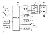
図1は上記イオン水生成器の制御ブロック図で、マイクロコンピュータからなる制御部17は制御プログラムを格納したROM18及び制御データを一時記憶するRAM19を備え、また図示しないがタイマを内蔵している。制御部17は待機状態において、吐水開始スイッチ5及び吐水終了スイッチ6からの信号を受け付けて、上水弁8、食塩水ポンプ11及び電源14をそれぞれオンオフ制御する。また、後述するように電極洗浄の時期が到来したと判断すると、一定時間、例えば5分間電極洗浄を行う。この電極洗浄は、極性切換回路15を切り換えて電極12,13に対する印加電圧の極性を反転するとともに、2つの三方弁16,16をいずれも排水口4側に切り換えて上水弁8を介して電解槽9に供給される水道水の電気分解を行い、生じたイオン水はすべて排水口4から排出するものである。極性切換回路15は図1に示すように、正極と負極とを入れ換える2個のリレーの組み合わせからなっている。なお、電極洗浄時には食塩水ポンプ11は動作させない。
【0008】
図4は電極洗浄時の制御部17の制御動作を示すフローチャートである。図4において、制御部17は食塩水ポンプ11が動作する度にその動作時間と、食塩水ポンプ11の単位時間当たりの吐出量とから食塩水の流量を演算し、その数値をRAM19に積算して記憶する(ステップS1)。そして、この積算流量QS と予め設定された一定値Q0 とを比較し(ステップS2)、積算流量QS が一定値Q0 に達したら(Q0 ≦QS )、電極12,13に対する印加電圧の極性を一定時間切り換えて電極洗浄を行う(ステップS3)。電極洗浄が完了したらRAM19内の積算流量データをクリアし(ステップS4)、待機状態に復帰する。
【0009】
図5は食塩水ポンプ11の動作時間に基づいて電極洗浄を実施する実施の形態を示すフローチャートで、図5において、制御部17は食塩水ポンプ11が動作する度にその動作時間をRAM19に積算して記憶する(ステップS1)。そして、この積算時間TS と予め設定された一定値T0 とを比較し(ステップS2)、積算流量TS が一定値T0 に達したら(T0 ≦TS )、電極12,13に対する印加電圧の極性を一定時間切り換えて電極洗浄を行う(ステップS3)。電極洗浄が完了したらRAM19内の積算流量データをクリアし(ステップS4)、待機状態に復帰する。
【0010】
【発明の効果】
この発明によれば、食塩水の流量あるいは供給時間の積算値が一定値に達した時点で自動的に電極洗浄を開始することにより、適切なタイミングで確実に電極洗浄を実行することでき、洗浄不十分によるイオン水の特性低下を有効に防止することができる。
【図面の簡単な説明】
【図1】この発明の実施の形態を示すイオン水生成器の制御ブロック図である。
【図2】この発明の実施の形態を示すイオン水生成器の外観を示す正面図である。
【図3】図2のイオン水生成器の内部構成図である。
【図4】図1のイオン水生成器の制御動作を示すフローチャートである。
【図5】図1のイオン水生成器の異なる制御動作を示すフローチャートである。
【符号の説明】
2 給水口
3 イオン水吐水口
5 吐水開始スイッチ
6 吐水終了スイッチ
7 表示部
9 電解槽
11 食塩水ポンプ
12 電極
13 電極
14 電源
15 極性切換回路[0001]
TECHNICAL FIELD OF THE INVENTION
The present invention relates to an ion water generator that generates ion water by electrolyzing water, and more particularly to an ion water generator that switches the polarity of a DC voltage applied to an electrode to perform electrode cleaning.
[0002]
[Prior art]
An ion that applies a DC voltage to the electrode while supplying tap water with saline added to the electrolytic cell in which the electrode is installed, and electrolyzes the water in the electrolytic cell to continuously generate acidic water or alkaline water In the water generator, if the electrolysis is continued, calcium ions and the like in the water accumulate on the electrodes, and the properties of the generated ionic water deteriorate. Therefore, in this case, the positive electrode and the negative electrode of the electrode are exchanged for a certain period of time, and a DC voltage is applied to remove deposits (called electrode cleaning).
[0003]
[Problems to be solved by the invention]
In that case, conventionally, electrode cleaning is performed manually at an appropriate time, and it has been difficult to reliably perform electrode cleaning at appropriate timing. An object of the present invention is to appropriately and reliably perform electrode cleaning to prevent a decrease in the quality of ionized water.
[0004]
In order to solve the above problems, the present invention is to apply a DC voltage to the electrode while supplying tap water with saline added to the electrolytic cell provided with the electrode, to electrolyze the water in the electrolytic cell. In an ion water generator that continuously generates ion water and performs electrode washing by switching the polarity of a DC voltage applied to the electrode, the discharge amount of the salt solution stored in the salt solution tank is reduced. Means for adding to the tap water by a constant saline pump and means for integrating the flow rate of the added saline from the operating time of the saline pump and the discharge amount per unit time or the operation of the saline pump A means for accumulating time and a control means for starting electrode cleaning when the accumulated flow rate or accumulated time reaches a certain value are provided.
[0005]
BEST MODE FOR CARRYING OUT THE INVENTION
Hereinafter, an embodiment of the present invention will be described with reference to FIGS. First, FIG. 2 is a front view showing the external appearance of an ion water generator, in which a
[0006]
FIG. 3 shows the internal configuration of the ion water generator. In FIG. 3, tap water entered from the
[0007]
FIG. 1 is a control block diagram of the above-mentioned ionized water generator. A
[0008]
FIG. 4 is a flowchart showing the control operation of the
[0009]
FIG. 5 is a flowchart showing an embodiment for performing electrode cleaning based on the operation time of the
[0010]
【The invention's effect】
According to the present invention, the electrode cleaning is automatically started when the integrated value of the flow rate or the supply time of the saline solution reaches a certain value, so that the electrode cleaning can be reliably performed at an appropriate timing. Deterioration of the characteristics of ion water due to insufficientness can be effectively prevented.
[Brief description of the drawings]
FIG. 1 is a control block diagram of an ion water generator showing an embodiment of the present invention.
FIG. 2 is a front view showing an appearance of an ion water generator according to the embodiment of the present invention.
FIG. 3 is an internal configuration diagram of the ion water generator of FIG. 2;
FIG. 4 is a flowchart showing a control operation of the ionized water generator of FIG.
FIG. 5 is a flowchart showing different control operations of the ion water generator of FIG. 1;
[Explanation of symbols]
2
Claims (2)
食塩水タンクに貯留された前記食塩水を吐出量が一定の食塩水ポンプにより水道水に添加するようにするとともに、この食塩水ポンプの動作時間と単位時間当たりの吐出量とから添加した前記食塩水の流量を積算する手段と、この積算流量が一定値に達したら電極洗浄を開始する制御手段とを設けたことを特徴とするイオン水生成器。A DC voltage is applied to the electrode while supplying tap water to which saline is added to the electrolytic cell in which the electrode is installed, and the water in the electrolytic cell is electrolyzed to continuously generate ionic water, and the electrode In the ion water generator, which performs electrode cleaning by switching the polarity of the DC voltage applied to the
The saline solution stored in the saline solution tank is added to tap water by a saline solution pump having a constant discharge amount, and the salt solution added from the operating time of the saline solution pump and the discharge amount per unit time. An ion water generator, comprising: means for integrating the flow rate of water; and control means for starting electrode cleaning when the integrated flow rate reaches a certain value.
食塩水タンクに貯留された前記食塩水を吐出量が一定の食塩水ポンプにより水道水に添加するようにするとともに、この食塩水ポンプの動作時間を積算する手段と、この積算時間が一定値に達したら電極洗浄を開始する制御手段とを設けたことを特徴とするイオン水生成器。A DC voltage is applied to the electrode while supplying tap water to which saline is added to the electrolytic cell in which the electrode is installed, and the water in the electrolytic cell is electrolyzed to continuously generate ionic water, and the electrode In the ion water generator, which performs electrode cleaning by switching the polarity of the DC voltage applied to the
Means for adding the salt solution stored in the salt solution tank to the tap water by a constant-rate pump with a constant discharge amount, and a means for integrating the operating time of the salt solution pump, and the integrated time is set to a constant value. And a control means for starting electrode cleaning when it is reached.
Priority Applications (1)
| Application Number | Priority Date | Filing Date | Title |
|---|---|---|---|
| JP16301998A JP3587289B2 (en) | 1998-05-27 | 1998-05-27 | Ion water generator |
Applications Claiming Priority (1)
| Application Number | Priority Date | Filing Date | Title |
|---|---|---|---|
| JP16301998A JP3587289B2 (en) | 1998-05-27 | 1998-05-27 | Ion water generator |
Publications (2)
| Publication Number | Publication Date |
|---|---|
| JPH11333459A JPH11333459A (en) | 1999-12-07 |
| JP3587289B2 true JP3587289B2 (en) | 2004-11-10 |
Family
ID=15765657
Family Applications (1)
| Application Number | Title | Priority Date | Filing Date |
|---|---|---|---|
| JP16301998A Expired - Fee Related JP3587289B2 (en) | 1998-05-27 | 1998-05-27 | Ion water generator |
Country Status (1)
| Country | Link |
|---|---|
| JP (1) | JP3587289B2 (en) |
-
1998
- 1998-05-27 JP JP16301998A patent/JP3587289B2/en not_active Expired - Fee Related
Also Published As
| Publication number | Publication date |
|---|---|
| JPH11333459A (en) | 1999-12-07 |
Similar Documents
| Publication | Publication Date | Title |
|---|---|---|
| JP3587289B2 (en) | Ion water generator | |
| JP3693381B2 (en) | Electrolyzed water generating apparatus and cleaning method thereof | |
| JPH0985244A (en) | Electrolytic water preparation device | |
| JP3547068B2 (en) | Ion water generator | |
| JP3580393B2 (en) | Ion water generator | |
| JP3975383B2 (en) | Electrolyzed water supply device | |
| JP3275106B2 (en) | Electrolytic ionic water generator | |
| JP3543365B2 (en) | Ionized water generator and pH sensor cleaning method | |
| JP3653135B2 (en) | Electrolyzed water generator | |
| JPH06320161A (en) | Water preparing apparatus | |
| JPH07256256A (en) | Apparatus for forming electrolytic ionic water | |
| JP3291107B2 (en) | Electrolytic ionic water generator | |
| JP3572662B2 (en) | Electrolyzed water generator | |
| JP3758945B2 (en) | Electrolyzed water generator | |
| JP3432119B2 (en) | Electrolyzed water generator | |
| JP3991484B2 (en) | Control method of alkaline ionized water apparatus | |
| JP3412669B2 (en) | Electrolyzed water generator | |
| JPH06343962A (en) | Alkaline ion water adjusting device | |
| JPH06320162A (en) | Water preparing apparatus | |
| JP3736051B2 (en) | Ion water conditioner | |
| JP2002028653A (en) | Electrolytic water feeder | |
| JPH08299958A (en) | Removing method for deposit in batch type electrolyzed water generator | |
| JP4010042B2 (en) | Electrolyzed water generator | |
| JPH09150154A (en) | Ionized water producing unit | |
| JP3601011B2 (en) | Electrolyzed water generator |
Legal Events
| Date | Code | Title | Description |
|---|---|---|---|
| A977 | Report on retrieval |
Free format text: JAPANESE INTERMEDIATE CODE: A971007 Effective date: 20040415 |
|
| A131 | Notification of reasons for refusal |
Free format text: JAPANESE INTERMEDIATE CODE: A131 Effective date: 20040430 |
|
| A521 | Written amendment |
Free format text: JAPANESE INTERMEDIATE CODE: A523 Effective date: 20040629 |
|
| TRDD | Decision of grant or rejection written | ||
| A01 | Written decision to grant a patent or to grant a registration (utility model) |
Free format text: JAPANESE INTERMEDIATE CODE: A01 Effective date: 20040722 |
|
| A61 | First payment of annual fees (during grant procedure) |
Free format text: JAPANESE INTERMEDIATE CODE: A61 Effective date: 20040804 |
|
| R150 | Certificate of patent or registration of utility model |
Free format text: JAPANESE INTERMEDIATE CODE: R150 |
|
| FPAY | Renewal fee payment (event date is renewal date of database) |
Free format text: PAYMENT UNTIL: 20070820 Year of fee payment: 3 |
|
| FPAY | Renewal fee payment (event date is renewal date of database) |
Free format text: PAYMENT UNTIL: 20080820 Year of fee payment: 4 |
|
| LAPS | Cancellation because of no payment of annual fees |