JP3736051B2 - Ion water conditioner - Google Patents
Ion water conditioner Download PDFInfo
- Publication number
- JP3736051B2 JP3736051B2 JP18105497A JP18105497A JP3736051B2 JP 3736051 B2 JP3736051 B2 JP 3736051B2 JP 18105497 A JP18105497 A JP 18105497A JP 18105497 A JP18105497 A JP 18105497A JP 3736051 B2 JP3736051 B2 JP 3736051B2
- Authority
- JP
- Japan
- Prior art keywords
- water
- value
- voltage
- electrolysis
- electrolytic
- Prior art date
- Legal status (The legal status is an assumption and is not a legal conclusion. Google has not performed a legal analysis and makes no representation as to the accuracy of the status listed.)
- Expired - Fee Related
Links
Images


Description
【0001】
【発明の属する技術分野】
本発明は、水道水等の原水を電気分解してアルカリイオン水および酸性イオン水を製造するイオン整水器に関するものである。
【0002】
【従来の技術】
イオン整水器は水道水等の原水を電気分解してイオン水を得るもので、飲用、医療用等としてはアルカリイオン水が、化粧水、殺菌洗浄水等としては酸性イオン水がそれぞれ用いられている。
【0003】
ここで、近年においては、連続電解方式のイオン整水器が普及している。このイオン整水器は、電解槽内で水道水等を電気分解して、陽極側に酸性イオン水を生成し、陰極側にアルカリイオン水を生成するものである。
【0004】
以下、従来の連続電解方式のイオン整水器について説明する。
従来のイオン整水器は、整水器内に流入する原水の流量を検出する流量センサ、この原水を電気分解するために電解槽に印加する電圧(以下、「電解電圧」という。)を出力する電解電圧印加手段、生成されたアルカリイオン水または酸性イオン水(以下、「イオン水」という。)や原水のpH値を検出するpHセンサ、電解槽に流れる電流(以下、「電解電流」という。)を検出する電解電流センサ、流量センサの検出流量から流量レベルを判断して電解電圧印加手段に出力する電解電圧を決定するとともにタイマーやデータの演算等を行う制御手段、生成したいイオン水のpH値をスイッチ等で設定するpH設定手段、電解電圧等のデータを記憶する記憶手段、不具合をLEDやブザーで知らせる警報手段から構成されている。
【0005】
そして、このような整水器に原水を流し込み、流量センサで検出された流量が記憶手段の任意の流量以上の場合(以下、「通水」という。)、設定pH値の通水した流量レベルに対応する電解電圧を記憶手段に予め記憶された任意の初期データから判断し、その電解電圧を印加する。この後、設定pH値とpH値を一定の速度で比較し、pH値が設定pH値のたとえば±0.1になるまで印加する電解電圧を一定の速度で増減する。そして、pH値が安定したときの電解電圧を設定pH値の当該流量レベルに対応する電解電圧として記憶手段に記憶する。
【0006】
同様に、設定pH値が切り換えられた場合や流量レベルが変化した場合には、変化した設定pH値や変化した流量レベルに対応した任意の初期データである電解電圧を記憶手段から判断して、その電解電圧を印加する。そして、生成されたイオン水のpH値が設定pH値の±0.1で安定したらそのときの電解電圧を記憶手段に記憶する。
【0007】
生成開始後は、記憶手段に記憶されている最大電解電流値と電解センサで検出された電解電流値とを比較し、検出電流値のほうが大きい場合には、過電流と判断して電解電圧出力を停止するとともに警報手段で作業者に知らせるようになっている。
【0008】
【発明が解決しようとする課題】
このように、従来の技術では、電解電圧を一定の速度で増減しつつ生成されたイオン水のpH値を設定pH値の所定範囲内で安定させるようにしているため、pH値を安定させるまでに時間を費やしてしまう。
【0009】
また、最初に通水した流量レベル以外の流量レベルでイオン水を生成する場合、新しい流量レベルでの通水開始時は記憶手段に記憶された任意の電解電圧が印加されるために、水質の違いで生成されたイオン水のpH値を設定pH値の所定範囲内で安定させるまでに時間を費やしてしまう。
【0010】
さらに、動作が止水から通水に移行した場合や通水状態で設定pH値を小さい値から大きい値に切り換えられた場合には、変更されたpH値の流量レベルに対応した電解電圧を印加するようにしているが、これでは生成されるイオン水のpH値が設定pH値の所定範囲内に近づくまでに時間を費やしてしまう。
【0011】
そして、イオン水の生成中に過電流が流れた場合には、制御手段に過負荷がかかって整水器の動作が不安定になる。
【0012】
そこで、本発明は、イオン水における設定pH値の所定範囲内までの到達時間を短縮することのできるイオン整水器を提供することを目的とする。
【0013】
また、本発明は、流量レベルが変化した場合において、イオン水のpH値を短時間のうちに設定pH値の所定範囲内で安定化させることのできるイオン整水器を提供することを目的とする。
【0014】
さらに、本発明は、動作が止水から通水に移行した場合や設定pH値が大きい値に切り換えられた場合において、イオン水のpH値を短時間のうちに設定pH値の所定範囲内で安定化させることのできるイオン整水器を提供することを目的とする。
【0015】
そして、本発明は、制御手段に過電流による過負荷がかかることのないイオン整水器を提供することを目的とする。
【0016】
【課題を解決するための手段】
この課題を解決するために、本発明のイオン整水器は、整水器内に流入する原水の流量を検出する流量センサと、原水を電気分解する一対の電極板に印加する電圧を出力する電解電圧印加手段と、生成されたイオン水または原水のpH値を検出するpHセンサと、電極板が設置された電解槽に流れる電流を検出する電解電流センサと、生成したいイオン水のpH値を設定するpH設定手段と、電極板に印加される電解電圧の増減とpH値の検出速度をpHセンサにより検出されたイオン水のpH値のレベルに応じて変化させてこのイオン水のpH値を設定pHの所定範囲内にする制御手段とを有するものである。これにより、イオン水における設定pH値の所定範囲内までの到達時間を短縮することができる。
【0017】
このイオン整水器において、制御手段により、最初に生成されたイオン水のpH値が設定pHの所定範囲内となったときの流量レベルと電解電圧から他の流量レベルにおける電解電圧を算出し、この電解電圧を電極板に印加するようにすることができる。これにより、イオン水のpH値を短時間のうちに設定pH値の所定範囲内で安定化させることができる。
【0018】
また、このイオン整水器において、制御手段により、止水から通水に移行した場合および通水中に小さいpH値から大きいpH値に設定が切り換えられた場合において、イオン水の生成開始から所定時間経過後より最大電解電圧を一定時間印加し、その後、設定された電解電圧を印加するようにすることができる。これにより、イオン水のpH値を短時間のうちに設定pH値の範囲内で安定化させることができる。
【0019】
さらに、このイオン整水器において、制御手段により、イオン水の生成開始から一定時間小さい電解電圧を印加して電解槽内の電解電流を検出するようにすることができる。これにより、過剰な電解電流が流れることが未然に防止され、過電流により制御手段に過負荷がかからない。
【0020】
【発明の実施の形態】
本発明の請求項1に記載の発明は、整水器内に流入する原水の流量を検出する流量センサと、原水を電気分解する一対の電極板に印加する電圧を出力する電解電圧印加手段と、生成されたイオン水または原水のpH値を検出するpHセンサと、電極板が設置された電解槽に流れる電流を検出する電解電流センサと、生成したいイオン水のpH値を設定するpH設定手段と、電極板に印加される電解電圧の増減とpH値の検出速度をpHセンサにより検出されたイオン水のpH値のレベルに応じて変化させてこのイオン水のpH値を設定pHの所定範囲内にする制御手段とを有するイオン整水器であり、イオン水における設定pH値の所定範囲内までの到達時間を短縮することができるという作用を有する。
【0021】
また、本発明の請求項2に記載の発明は、請求項1記載の発明において、制御手段により、最初に生成されたイオン水のpH値が設定pHの所定範囲内となったときの流量レベルと電解電圧から他の流量レベルにおける電解電圧を算出し、この電解電圧を電極板に印加することとしたイオン整水器であり、イオン水のpH値を短時間のうちに設定pH値の所定範囲内で安定化させることができるという作用を有する。
【0022】
さらに、本発明の請求項3に記載の発明は、請求項1または2記載の発明において、制御手段により、止水から通水に移行した場合および通水中に小さいpH値から大きいpH値に設定が切り換えられた場合において、イオン水の生成開始から所定時間経過後より最大電解電圧を一定時間印加し、その後、設定された電解電圧を印加することとしたイオン整水器であり、イオン水のpH値を短時間のうちに設定pH値の範囲内で安定化させることができるという作用を有する。
【0023】
そして、本発明の請求項4に記載の発明は、請求項1、2または3記載の発明において、制御手段により、イオン水の生成開始から一定時間小さい電解電圧を印加して電解槽内の電解電流を検出することとしたイオン整水器であり、過剰な電解電流が流れることが未然に防止されて過電流により制御手段に過負荷がかからないという作用を有する。
【0024】
以下、本発明の実施の形態について、図1から図5を用いて説明する。なお、これらの図面において同一の部材には同一の符号を付しており、また、重複した説明は省略されている。
【0025】
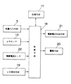
図1は本発明の一実施の形態であるイオン整水器の構成を示す概略図、図2は図1のイオン整水器における制御系を示すブロック図、図3は図1のイオン整水器において原水から設定pH値の所定範囲内のイオン水を生成する手順を示すフローチャート、図4は図1のイオン整水器において流量レベルが変化した場合における原水から設定pH値の所定範囲内のイオン水を生成する手順を示すフローチャート、図5は図1のイオン整水器において設定pH値が大きい値に切り換えられた場合における原水から設定pH値の所定範囲内のイオン水を生成する手順を示すフローチャートである。
【0026】
図1において、アルカリイオン水や酸性イオン水が生成されるイオン整水器3には水道水等の原水を導入するための原水管1が接続されている。原水管1には水栓2が取り付けられており、この水栓2を操作することによって原水管1の管路が開放または遮断される。
【0027】
イオン整水器3には、原水中の残留塩素を吸収する活性炭および一般細菌や不純物を取り除く中空糸膜等を備えた浄水部4が原水管1に接続されて設けられている。この浄水部4には通水された水を電気分解する電解槽7が接続されており、浄水部4と電解槽7との間には、配管内の原水の流量を測定する流量センサ5、グリセロリン酸カルシウムや乳酸カルシウム等のカルシウムイオンを原水中に付与して導電率を高めるカルシウム供給部6が順次設置されている。
【0028】
電解槽7には内部を2つの電解室7a、7bに区画する隔膜8が設けられ、各電解室7a、7bには電極板9、10が配設されている。それぞれの電解室7a、7bには吐出管12、18が取り付けられており、電極板9の配設された電解室7a内の水および電極板10の配設された電解室7bの水は各吐出管12、18を通して外部に排出される。
【0029】
カルシウム供給部6と電解槽7との間から吐出管18に連通してバイパス配管23が設けられている。バイパス配管23には、イオン水生成時には閉位置とされる電磁弁11が設置されている。そして、この電磁弁11を開くことにより、電解槽7内の洗浄に用いられた水がバイパス配管23から吐出管18を通って排出される。
【0030】
吐出管12と吐出管18とを連通するようにしてセンサ用配管24が設けられており、このセンサ用配管24には、原水や生成された水のpH値を検出するpHセンサ13が取り付けられている。
【0031】
このような配管構造を有するイオン整水器3には、このイオン整水器3の動作を制御するMPUなどの制御手段14が設けられている。
【0032】
図2において詳しく示すように、制御手段14には前述した流量センサ5、電磁弁11、pHセンサ13が電気的に接続されており、導入された水の流量データが流量センサ5から制御手段14へ送られ、バイパス配管23の開閉が制御手段14によりコントロールされ、そして電解槽7を経た水のpH値のデータがpHセンサ13から制御手段14へ送られるようになっている。
【0033】
また、この制御手段14には、電極板9、10に電解電圧を印加するFET等の電解電圧印加手段21、この電解電圧印加手段21で印加される電解電圧によって電解槽7に流れる電解電流を検出する電解電流センサ22、イオン整水器3により生成したいpH値を設定するpH設定手段19およびイオン整水器3における過電流等の異常を表示やブザー等で知らせる警報手段20が電気的に接続されている。したがって、制御手段14では、pH設定手段19から送られたpH値と電解電流センサ22から送られた電解電流値とにより電極板9、10に印加する電解電圧値を判断し、タイマー、およびデータの演算等を行う。
【0034】
さらに、制御手段14には記憶手段17が電気的に接続されている。記憶手段17は、プログラムとデータの初期値(定数)等を記憶するROMと動作するために必要なデータ(可変数)等を記憶するRAM、電源が切られても保持データを記憶しているEEPROMなどから構成されており、イオン整水器3の動作情報等はこの記憶手段17に記憶される。
【0035】
なお、このような制御手段14は、電源投入用プラグ15から取り入れられて電源部16において交流電流から変換された直流電流により動作される。
【0036】
次に、以上のように構成された本実施の形態におけるイオン整水器3について、イオン水を生成する動作を説明する。
【0037】
先ず、利用者は生成したいアルカリイオン水または酸性イオン水のpH値をpH設定手段19で入力し、水栓2を開く。これにより原水管1から通水された原水は、浄水部4で原水中の残留塩素や不純物が取り除かれ、流量センサ5で通水量が検出され、カルシウム供給部6でグリセロリン酸カルシウム等が溶解されて電解容易な水に処理された後、電解槽7に案内される。
【0038】
一方、電源投入用プラグ15からはたとえばAC100Vの電圧が供給され、電源部16で制御用の直流電圧に変換される。そして、電解室7a、7b内に設けられた電極板9、10に相互に極性の異なる電圧であるプラス電圧、マイナス電圧が印加される。これにより、陽極室、陰極室が形成され、陰極室側にアルカリイオン水が、陽極室側に酸性イオン水が生成される。
【0039】
流量センサ5に検出された流量レベルが所定値以上となったとき、制御手段14により通水と判断される。このときpH設定手段19で電解条件が設定されているので、制御手段14は電解槽7により電気分解を行うための電解電圧を電解電圧印加手段21を介して電極板9、10に印加する。その結果、設定されたpH値レベルの生成水が吐水管12から吐水される。
【0040】
なお、イオン整水器3が止水状態になったとき、あるいは所定の洗浄条件を満たしたとき、電極板9、10に印加する電圧の極性を反転して電極板9、10を洗浄する。洗浄終了後は、制御手段14により電磁弁11を開き、バイパス配管23、排水管18より洗浄水が排出される。
【0041】
ここで、本実施の形態におけるイオン整水器3において原水から設定pH値の所定範囲内のイオン水を生成するプロセスを図3を用いて説明する。なお、本実施の形態においては、設定pH値の±0.1範囲内のイオン水を生成する場合について説明するが、設定pH値に対する範囲は自由に規定することができる。また、流量レベルは4段階とされているが、これも自由に設定することができる。
【0042】
図3において、流量センサ5で検出されて制御手段14に入力された流量が記憶手段17に記憶された流量値以上でない場合(以下、「止水」という。)には、電解電圧出力が停止される(ステップ1)。
【0043】
一方、流量センサ5による流量が記憶手段17に記憶された流量値以上である場合(以下、「通水」という。)には、pH設定手段19で設定されたモードが浄水モードかどうかが判断され(ステップ2)、浄水モードであれば電解電圧出力が停止される。また、アルカリあるいは酸性モードであれば、通水開始から20〜40秒経過したかどうか、つまりpH値の制御を許可してもよいかが判断される(ステップ3)。そして、禁止であればステップ1に戻り、許可であれば生成イオン水のpH値がpHセンサ13から制御手段14に入力される(ステップ4)。その後、pH値制御速度の初期設定が終了したかどうかが判断される(ステップ5)。
【0044】
初期設定が終了していれば電解電圧が印加される(ステップ6)。未設定であれば制御速度(0.5〜2秒程度)の初期設定が行われ、記憶手段17に記憶された任意に設定された初期データの電解電圧が印加される(ステップ7)。
【0045】
ステップ6の後、設定されたpH制御速度をカウントして、カウントオーバーでなければステップ1に戻る(ステップ8)。また、カウントオーバーしていれば、ステップ4で制御手段14に入力されたイオン水のpH値が設定pH値の±0.1の範囲内であるかが判断され(ステップ9)、範囲内であれば制御速度4(2〜8秒程度)が設定される。範囲外であればイオン水のpH値が設定pH値の±0.2の範囲内であるかが判断され(ステップ10)、範囲内であれば制御速度3(2〜8秒程度)が設定される。範囲外であればイオン水のpH値が設定pH値の±0.3の範囲内であるかが判断され(ステップ11)、範囲内であれば制御速度2(2〜8秒程度)が設定される。さらに、範囲外であれば(ステップ12)、制御速度1(0.5〜2秒程度)が設定される。
【0046】
そして、イオン水のpH値が設定pH値の±0.1の範囲内であれば、その時の電解電圧が設定pH値と流量レベルに対応した電解電圧として記憶手段17に記憶され(ステップ13)、範囲外であれば、範囲内になるように電解電圧が増減され(ステップ14)、ステップ1に戻される。
【0047】
このように、本実施の形態によるイオン整水器によれば、電極板9、10に印加される電解電圧の増減とpH値の検出速度をpHセンサ13により検出されたイオン水のpH値のレベルに応じて変化させてこのイオン水のpH値を設定pHの±0.1範囲内にすることとしているので、イオン水における設定pH値の±0.1の範囲内までの到達時間を短縮することができる。
【0048】
ここで、原水の流量レベルが変化した場合におけるイオン水のpH値制御について説明する。
【0049】
図4において、イオン整水器3に最初に通水し、あるpH値における任意の流量レベルで、前述したようなステップ1〜14によって電解電圧の初期設定がされる。そして、この初期設定が終了したかどうかが判断され(ステップ15)、終了していなければ初期設定が行われる。また、終了していれば、初期設定の流量レベルに対応した電解電圧以外の電解電圧が各設定pH値において演算されて記憶手段17に記憶される(ステップ16)。
【0050】
ここで、演算方法としては、初期設定で設定された電解電圧と予め記憶手段17に記憶された設定pH値の流量レベルに対応する電解電圧データとの差を求め、その差の最大値、最小値の範囲内で増減算して他の流量レベルにおける電解電圧を求める。
【0051】
各設定pH値において、2回目以降の通水は、ステップ1〜14で設定された電解電圧について、記憶手段17で前回記憶されたデータを更新して記憶する。
【0052】
このように、本実施の形態によるイオン整水器によれば、最初に通水されて生成されたイオン水のpH値が設定pHの±0.1範囲内となったときの流量レベルと電解電圧から他の流量レベルにおける電解電圧を算出し、この電解電圧を印加することとしているので、流量レベルが変化した場合には、演算で得られた電解電圧値を印加することにより、水質に関係なく、イオン水のpH値を短時間のうちに設定pH値の±0.1の範囲内で安定化させることができる。
【0053】
次に、動作が止水から通水に移行した場合、設定pH値が大きい値に切り換えられた場合におけるイオン水のpH値制御について説明する。
【0054】
イオン整水器に原水を通水した後、図5において、アルカリまたは酸性モードにおいて生成開始からm秒(1〜2秒程度)経過したかどうかが判断される(ステップ17)。そして、経過していなければ、ステップ18において、有する能力の10〜15%程度の電解電圧(以下、「電解電圧X%」という。)が印加される。また、経過していれば生成開始n秒(3〜5秒程度)経過したかどうかが判断される(ステップ22)。そして、経過していれば設定されたpH値と流量レベルに対応した電解電圧が印加される(ステップ23)。また、経過していなければ止水から通水、または通水中にpH設定値が小さい値から大きい値に切り換えられたかどうかが判断される(ステップ24)。切り換えられていれば、100%の電解電圧が印加され(ステップ25)、そうでなければステップ23に移行される。
【0055】
一方、ステップ18で電解電圧X%を印加するとき、電解槽7内の電解電流値が電解電流センサ22から制御手段14に入力される(ステップ19)。そして、入力された電解電流値と記憶手段17で記憶された最大電解電流値とが比較される(ステップ20)。その結果、入力された電解電流値が最大電解電流値より大きい場合には、過電流と判断され電解電圧の印加が停止されるとともに警報手段20により作業者に警報が発出される(ステップ21)。また、小さい場合には、そのまま電解電圧X%が印加される。
【0056】
このように、本実施の形態によるイオン整水器によれば、止水から通水に移行した場合や通水中に小さいpH値から大きいpH値に設定が切り換えられた場合、イオン水の生成開始から所定時間経過後より最大電解電圧を一定時間印加し、その後、設定された電解電圧を印加するようにしているので、イオン水のpH値を短時間のうちに設定pH値の範囲内で安定化させることができる。
【0057】
また、設定pH値において、イオン水の生成開始から一定時間小さい電解電圧を印加して電解槽内の電解電流を検出するようにしているので、過剰な電解電流が流れることが未然に防止され、過電流により制御手段14に過負荷がかかることはない。
【0058】
【発明の効果】
以上のように、本発明によれば、電極板に印加される電解電圧の増減とpH値の検出速度をpHセンサにより検出されたイオン水のpH値のレベルに応じて変化させてこのイオン水のpH値を設定pHの所定範囲内にすることとしているので、イオン水における設定pH値の所定範囲内までの到達時間を短縮することができるという有効な効果が得られる。
【0059】
また、本発明によれば、最初に通水されて生成されたイオン水のpH値が設定pHの所定範囲内となったときの流量レベルと電解電圧から他の流量レベルにおける電解電圧を算出し、この電解電圧を印加することとしているので、流量レベルが変化した場合に当該電解電圧値を印加することにより、水質に関係なく、イオン水のpH値を短時間のうちに設定pH値の所定の範囲内で安定化させることができるという有効な効果が得られる。
【0060】
さらに、本発明によれば、止水から通水に移行した場合や通水中に小さいpH値から大きいpH値に設定が切り換えられた場合、イオン水の生成開始から所定時間経過後より最大電解電圧を一定時間印加し、その後、設定された電解電圧を印加するようにしているので、イオン水のpH値を短時間のうちに設定pH値の範囲内で安定化させることができるという有効な効果が得られる。
【0061】
そして、本発明によれば、設定pH値において、イオン水の生成開始から一定時間小さい電解電圧を印加して電解槽内の電解電流を検出するようにしているので、過剰な電解電流が流れることが未然に防止され、過電流により制御手段に過負荷がかからないという有効な効果が得られる。
【図面の簡単な説明】
【図1】本発明の一実施の形態であるイオン整水器の構成を示す概略図
【図2】図1のイオン整水器における制御系を示すブロック図
【図3】図1のイオン整水器において原水から設定pH値の所定範囲内のイオン水を生成する手順を示すフローチャート
【図4】図1のイオン整水器において流量レベルが変化した場合における原水から設定pH値の所定範囲内のイオン水を生成する手順を示すフローチャート
【図5】図1のイオン整水器において設定pH値が大きい値に切り換えられた場合における原水から設定pH値の所定範囲内のイオン水を生成する手順を示すフローチャート
【符号の説明】
5 流量センサ
7 電解槽
9,10 電極板
13 pHセンサ
14 制御手段
19 pH設定手段
21 電解電圧印加手段
22 電解電流センサ[0001]
BACKGROUND OF THE INVENTION
The present invention relates to an ion water conditioner that electrolyzes raw water such as tap water to produce alkali ion water and acidic ion water.
[0002]
[Prior art]
An ion water conditioner electrolyzes raw water such as tap water to obtain ionic water. Alkaline ionic water is used for drinking, medical use, etc. ing.
[0003]
Here, in recent years, a continuous electrolysis type ion water conditioner has become widespread. This ion water conditioner electrolyzes tap water or the like in an electrolytic cell to generate acidic ion water on the anode side and alkali ion water on the cathode side.
[0004]
Hereinafter, a conventional continuous electrolysis type ion water conditioner will be described.
A conventional ion water conditioner outputs a flow rate sensor that detects the flow rate of raw water flowing into the water conditioner, and a voltage (hereinafter referred to as “electrolysis voltage”) that is applied to an electrolytic cell to electrolyze the raw water. Electrolytic voltage application means, pH sensor for detecting the pH value of the generated alkaline ionized water or acidic ionized water (hereinafter referred to as “ionic water”) or raw water, current flowing in the electrolytic cell (hereinafter referred to as “electrolytic current”) )), A control means for determining the flow level from the flow rate detected by the flow sensor and determining the electrolytic voltage to be output to the electrolytic voltage application means, and for calculating a timer and data, etc., and for the ionic water to be generated It comprises a pH setting means for setting a pH value with a switch, a storage means for storing data such as an electrolysis voltage, and an alarm means for informing a malfunction with an LED or a buzzer.
[0005]
Then, when raw water is poured into such a water conditioner and the flow rate detected by the flow sensor is equal to or higher than an arbitrary flow rate of the storage means (hereinafter referred to as “water flow”), the flow rate level at which the set pH value has passed. Is determined from any initial data stored in advance in the storage means, and the electrolysis voltage is applied. Thereafter, the set pH value and the pH value are compared at a constant rate, and the applied electrolysis voltage is increased or decreased at a constant rate until the pH value becomes, for example, ± 0.1 of the set pH value. Then, the electrolytic voltage when the pH value is stabilized is stored in the storage means as the electrolytic voltage corresponding to the flow rate level of the set pH value.
[0006]
Similarly, when the set pH value is switched or the flow rate level is changed, an electrolytic voltage that is arbitrary initial data corresponding to the changed set pH value or changed flow rate level is determined from the storage means, The electrolytic voltage is applied. When the pH value of the generated ionized water is stabilized at ± 0.1 of the set pH value, the electrolysis voltage at that time is stored in the storage means.
[0007]
After the start of generation, the maximum electrolysis current value stored in the storage means is compared with the electrolysis current value detected by the electrolysis sensor, and if the detected current value is larger, it is judged as an overcurrent and the electrolysis voltage is output. Is stopped and an alarm means is used to notify the operator.
[0008]
[Problems to be solved by the invention]
As described above, in the conventional technique, the pH value of the generated ionic water is stabilized within a predetermined range of the set pH value while increasing / decreasing the electrolysis voltage at a constant rate, so that the pH value is stabilized. Spending time on.
[0009]
In addition, when ionic water is generated at a flow rate level other than the flow rate level at which the water first flows, an arbitrary electrolysis voltage stored in the storage means is applied at the start of water flow at the new flow level. It takes time to stabilize the pH value of the ionic water generated by the difference within a predetermined range of the set pH value.
[0010]
Furthermore, when the operation shifts from water stoppage to water flow or when the set pH value is switched from a small value to a large value in the water flow state, an electrolytic voltage corresponding to the flow rate level of the changed pH value is applied. However, in this case, it takes time until the pH value of the generated ionic water approaches the predetermined range of the set pH value.
[0011]
And when an overcurrent flows during the production | generation of ionic water, an overload will be applied to a control means and operation | movement of a water conditioner will become unstable.
[0012]
Then, an object of this invention is to provide the ion water conditioner which can shorten the arrival time to within the predetermined range of the setting pH value in ion water.
[0013]
Another object of the present invention is to provide an ion water conditioner that can stabilize the pH value of ionic water within a predetermined range of the set pH value in a short time when the flow rate level changes. To do.
[0014]
Further, according to the present invention, when the operation shifts from water stoppage to water passage or when the set pH value is switched to a large value, the pH value of the ionic water is within a predetermined range of the set pH value within a short time. An object of the present invention is to provide an ion water conditioner that can be stabilized.
[0015]
An object of the present invention is to provide an ion water conditioner in which an overload due to an overcurrent is not applied to the control means.
[0016]
[Means for Solving the Problems]
In order to solve this problem, the ion water adjuster of the present invention outputs a voltage applied to a pair of electrode plates that electrolyze the raw water and a flow rate sensor that detects the flow rate of the raw water flowing into the water adjuster. An electrolytic voltage application means, a pH sensor for detecting the pH value of the generated ionic water or raw water, an electrolytic current sensor for detecting the current flowing in the electrolytic cell in which the electrode plate is installed, and the pH value of the ionic water to be generated The pH setting means to set, the increase / decrease of the electrolysis voltage applied to the electrode plate, and the detection speed of the pH value are changed according to the pH value level of the ionic water detected by the pH sensor, and the pH value of the ionic water is changed. And a control means for setting the pH within a predetermined range. Thereby, the arrival time to within the predetermined range of the setting pH value in ion water can be shortened.
[0017]
In this ion water conditioner, the control means calculates the electrolysis voltage at the other flow level from the flow level and the electrolysis voltage when the pH value of the first generated ionic water falls within the predetermined range of the set pH, This electrolytic voltage can be applied to the electrode plate. Thereby, the pH value of ionic water can be stabilized within a predetermined range of the set pH value in a short time.
[0018]
Further, in this ion water conditioner, when the control means shifts from water stoppage to water flow and when the setting is switched from a small pH value to a large pH value during the water flow, a predetermined time from the start of generation of the ion water. The maximum electrolysis voltage can be applied for a certain period of time after the elapse of time, and then the set electrolysis voltage can be applied. Thereby, the pH value of ionic water can be stabilized within the set pH value within a short time.
[0019]
Furthermore, in this ion water conditioner, the electrolysis voltage in the electrolytic cell can be detected by applying a small electrolysis voltage for a certain time from the start of the production of ionic water by the control means. As a result, an excessive electrolytic current is prevented from flowing in advance, and the control means is not overloaded by the overcurrent.
[0020]
DETAILED DESCRIPTION OF THE INVENTION
According to the first aspect of the present invention, a flow rate sensor that detects a flow rate of raw water flowing into a water conditioner, and an electrolytic voltage application unit that outputs a voltage applied to a pair of electrode plates for electrolyzing the raw water. A pH sensor for detecting the pH value of the generated ionic water or raw water, an electrolysis current sensor for detecting the current flowing in the electrolytic cell in which the electrode plate is installed, and a pH setting means for setting the pH value of the ionic water to be generated And changing the electrolytic voltage applied to the electrode plate and the pH value detection speed according to the pH level of the ionic water detected by the pH sensor to set the pH value of the ionic water within a predetermined pH range. The ion water adjuster having the control means to be inside has an effect that it is possible to shorten the arrival time until the set pH value in the ion water is within a predetermined range.
[0021]
Further, the invention according to
[0022]
Furthermore, the invention according to claim 3 of the present invention is the invention according to
[0023]
And, in the invention according to
[0024]
Hereinafter, embodiments of the present invention will be described with reference to FIGS. In these drawings, the same members are denoted by the same reference numerals, and redundant description is omitted.
[0025]
FIG. 1 is a schematic diagram showing a configuration of an ion water conditioner according to an embodiment of the present invention, FIG. 2 is a block diagram showing a control system in the ion water adjuster of FIG. 1, and FIG. 3 is an ion water conditioner of FIG. FIG. 4 is a flowchart showing a procedure for generating ionic water within a predetermined range of the set pH value from the raw water in the apparatus, and FIG. 4 is a flowchart showing a procedure for generating the ionic water within the predetermined range of the set pH value from the raw water when the flow rate level changes in the ion water conditioner of FIG. FIG. 5 is a flowchart showing a procedure for generating ionic water, and FIG. 5 shows a procedure for generating ionic water within a predetermined range of the set pH value from the raw water when the set pH value is switched to a large value in the ion water conditioner of FIG. It is a flowchart to show.
[0026]
In FIG. 1, a raw water pipe 1 for introducing raw water such as tap water is connected to an ion water conditioner 3 in which alkaline ionized water or acidic ionized water is generated. A
[0027]
The ion water adjuster 3 is provided with a
[0028]
The
[0029]
A
[0030]
A
[0031]
The ion water adjuster 3 having such a piping structure is provided with a control means 14 such as an MPU that controls the operation of the ion water adjuster 3.
[0032]
As shown in detail in FIG. 2, the
[0033]
Further, the control means 14 includes an electrolytic voltage applying means 21 such as an FET for applying an electrolytic voltage to the
[0034]
Further, a storage means 17 is electrically connected to the control means 14. The
[0035]
Such control means 14 is operated by a direct current that is taken in from the power-on
[0036]
Next, the operation | movement which produces | generates ion water is demonstrated about the ion water conditioner 3 in this Embodiment comprised as mentioned above.
[0037]
First, the user inputs the pH value of alkaline ion water or acidic ion water to be generated by the pH setting means 19 and opens the
[0038]
On the other hand, for example, a voltage of AC 100 V is supplied from the power-on
[0039]
When the flow rate level detected by the
[0040]
When the ion water conditioner 3 is in a water-stopped state or when a predetermined cleaning condition is satisfied, the polarity of the voltage applied to the
[0041]
Here, a process of generating ionic water within a predetermined range of the set pH value from raw water in the ionic water conditioner 3 in the present embodiment will be described with reference to FIG. In the present embodiment, the case of generating ionic water within a range of ± 0.1 of the set pH value will be described, but the range for the set pH value can be freely defined. Moreover, although the flow level is made into four steps, this can also be set freely.
[0042]
In FIG. 3, when the flow rate detected by the
[0043]
On the other hand, when the flow rate by the
[0044]
If the initial setting is completed, an electrolytic voltage is applied (step 6). If not set, the control speed (about 0.5 to 2 seconds) is initially set, and the electrolysis voltage of arbitrarily set initial data stored in the storage means 17 is applied (step 7).
[0045]
After
[0046]
If the pH value of the ionic water is within ± 0.1 of the set pH value, the electrolysis voltage at that time is stored in the storage means 17 as an electrolysis voltage corresponding to the set pH value and the flow rate level (step 13). If it is out of the range, the electrolysis voltage is increased or decreased to be within the range (step 14), and the process returns to step 1.
[0047]
As described above, according to the ion water conditioner according to the present embodiment, the increase / decrease of the electrolysis voltage applied to the
[0048]
Here, pH value control of ionic water when the flow rate level of raw water changes will be described.
[0049]
In FIG. 4, water is first passed through the ion water conditioner 3, and the initial setting of the electrolytic voltage is performed by steps 1 to 14 as described above at an arbitrary flow rate level at a certain pH value. Then, it is determined whether or not the initial setting has been completed (step 15). If it has not been completed, the initial setting is performed. If completed, an electrolysis voltage other than the electrolysis voltage corresponding to the initially set flow level is calculated at each set pH value and stored in the storage means 17 (step 16).
[0050]
Here, as a calculation method, the difference between the electrolytic voltage set in the initial setting and the electrolytic voltage data corresponding to the flow level of the set pH value stored in advance in the
[0051]
In each set pH value, the second and subsequent water flows update and store the data previously stored in the
[0052]
As described above, according to the ion water conditioner according to the present embodiment, the flow rate level and electrolysis when the pH value of the ionic water generated by first passing water is within the range of ± 0.1 of the set pH. Since the electrolysis voltage at other flow levels is calculated from the voltage and this electrolysis voltage is applied, when the flow level changes, the electrolysis voltage value obtained by the calculation is applied, and this is related to the water quality. In addition, the pH value of the ionic water can be stabilized within a range of ± 0.1 of the set pH value in a short time.
[0053]
Next, the pH value control of ionic water when the operation is shifted from water stoppage to water passage and the set pH value is switched to a large value will be described.
[0054]
After the raw water is passed through the ion water conditioner, it is determined in FIG. 5 whether or not m seconds (about 1 to 2 seconds) have elapsed since the start of generation in the alkaline or acidic mode (step 17). If not, in
[0055]
On the other hand, when the electrolytic voltage X% is applied in
[0056]
As described above, according to the ion water adjuster according to the present embodiment, when transition from water stoppage to water flow or when the setting is switched from a small pH value to a large pH value during water flow, the generation of ionic water is started. Since the maximum electrolysis voltage is applied for a certain period of time after the elapse of time, and then the set electrolysis voltage is applied, the pH value of the ionic water is stable within the set pH value within a short time. It can be made.
[0057]
In addition, at the set pH value, the electrolytic current in the electrolytic cell is detected by applying a small electrolysis voltage for a certain time from the start of the production of ionic water, so that an excessive electrolysis current is prevented from flowing in advance. The overload is not applied to the control means 14 due to the overcurrent.
[0058]
【The invention's effect】
As described above, according to the present invention, an increase or decrease in the electrolysis voltage applied to the electrode plate and the detection speed of the pH value are changed according to the level of the pH value of the ionic water detected by the pH sensor. Since the pH value is set within the predetermined range of the set pH, an effective effect that the time required for the ion water to reach the predetermined range of the set pH value can be shortened.
[0059]
In addition, according to the present invention, the electrolysis voltage at another flow rate level is calculated from the flow rate level and the electrolysis voltage when the pH value of the ionic water generated by first passing water is within the predetermined range of the set pH. Since this electrolytic voltage is applied, by applying the electrolytic voltage value when the flow level changes, regardless of the water quality, the pH value of the ionic water is set to the predetermined pH value within a short time. The effective effect that it can stabilize within the range of this is acquired.
[0060]
Furthermore, according to the present invention, the maximum electrolysis voltage after a lapse of a predetermined time from the start of generation of ionic water when the water flow is changed from water stoppage to water flow or when the setting is switched from a small pH value to a large pH value during the water flow. Is applied for a certain period of time, and then the set electrolysis voltage is applied, so that the pH value of the ionic water can be stabilized within the set pH value within a short time. Is obtained.
[0061]
According to the present invention, at the set pH value, an electrolysis voltage in the electrolytic cell is detected by applying a small electrolysis voltage for a certain time from the start of the generation of ionic water, so that an excessive electrolysis current flows. Is effectively prevented, and an effective effect that the control means is not overloaded by the overcurrent is obtained.
[Brief description of the drawings]
FIG. 1 is a schematic diagram showing a configuration of an ion water conditioner according to an embodiment of the present invention. FIG. 2 is a block diagram showing a control system in the ion water conditioner of FIG. FIG. 4 is a flowchart showing a procedure for generating ionic water within a predetermined range of a set pH value from raw water in the water device. FIG. 4 is a flow chart of the ion water adjuster shown in FIG. FIG. 5 is a flowchart showing a procedure for generating ionic water within a predetermined range of the set pH value from the raw water when the set pH value is switched to a large value in the ion water conditioner of FIG. Flowchart showing explanation [Explanation of symbols]
DESCRIPTION OF
Claims (4)
前記原水を電気分解する一対の電極板に印加する電圧を出力する電解電圧印加手段と、
生成されたイオン水または原水のpH値を検出するpHセンサと、
前記電極板が設置された電解槽に流れる電流を検出する電解電流センサと、
生成したいイオン水のpH値を設定するpH設定手段と、
前記電極板に印加される電解電圧の増減とpH値の検出速度を前記pHセンサにより検出された前記イオン水のpH値のレベルに応じて変化させてこのイオン水のpH値を設定pHの所定範囲内にする制御手段とを有することを特徴とするイオン整水器。A flow sensor for detecting the flow rate of the raw water flowing into the water conditioner;
An electrolytic voltage applying means for outputting a voltage to be applied to a pair of electrode plates for electrolyzing the raw water;
A pH sensor for detecting the pH value of the generated ionic water or raw water;
An electrolytic current sensor for detecting a current flowing in an electrolytic cell in which the electrode plate is installed;
PH setting means for setting the pH value of ionic water to be generated;
The pH value of the ionic water is set to a predetermined pH by changing the electrolysis voltage applied to the electrode plate and the detection speed of the pH value according to the level of the pH value of the ionic water detected by the pH sensor. And an ion water adjuster characterized by having control means within the range.
Priority Applications (1)
| Application Number | Priority Date | Filing Date | Title |
|---|---|---|---|
| JP18105497A JP3736051B2 (en) | 1997-07-07 | 1997-07-07 | Ion water conditioner |
Applications Claiming Priority (1)
| Application Number | Priority Date | Filing Date | Title |
|---|---|---|---|
| JP18105497A JP3736051B2 (en) | 1997-07-07 | 1997-07-07 | Ion water conditioner |
Publications (2)
| Publication Number | Publication Date |
|---|---|
| JPH1119647A JPH1119647A (en) | 1999-01-26 |
| JP3736051B2 true JP3736051B2 (en) | 2006-01-18 |
Family
ID=16093979
Family Applications (1)
| Application Number | Title | Priority Date | Filing Date |
|---|---|---|---|
| JP18105497A Expired - Fee Related JP3736051B2 (en) | 1997-07-07 | 1997-07-07 | Ion water conditioner |
Country Status (1)
| Country | Link |
|---|---|
| JP (1) | JP3736051B2 (en) |
Families Citing this family (1)
| Publication number | Priority date | Publication date | Assignee | Title |
|---|---|---|---|---|
| JP4955844B2 (en) * | 1999-06-21 | 2012-06-20 | パナソニック株式会社 | Alkaline ion water conditioner |
-
1997
- 1997-07-07 JP JP18105497A patent/JP3736051B2/en not_active Expired - Fee Related
Also Published As
| Publication number | Publication date |
|---|---|
| JPH1119647A (en) | 1999-01-26 |
Similar Documents
| Publication | Publication Date | Title |
|---|---|---|
| CA2639613C (en) | Electrolyzed water producing method and apparatus | |
| JP3149138B2 (en) | Control device for continuous electrolytic ionized water generator | |
| JPH06343959A (en) | Alkaline ion water adjusting device | |
| JP2810262B2 (en) | Control device for continuous electrolytic ionized water generator | |
| JP4955844B2 (en) | Alkaline ion water conditioner | |
| JP3736051B2 (en) | Ion water conditioner | |
| JP3991484B2 (en) | Control method of alkaline ionized water apparatus | |
| JP3358236B2 (en) | Alkaline ion water purifier | |
| JP3572661B2 (en) | Electrolyzed water generator | |
| JPH06320161A (en) | Water preparing apparatus | |
| JP3572662B2 (en) | Electrolyzed water generator | |
| JPH06335681A (en) | Alkaline ion water regulator | |
| JP4378803B2 (en) | Alkaline ion water conditioner | |
| JP4244395B2 (en) | Alkaline ion water conditioner | |
| JP3461030B2 (en) | Alkaline ion water purifier | |
| JP3297828B2 (en) | Electrolyzed water generator and method for controlling chloride ion concentration in the electrolyzed water generator | |
| JP3329872B2 (en) | Control device for continuous electrolyzed water generator | |
| JPH1080685A (en) | Alkali ionized water adjuster | |
| JP3975383B2 (en) | Electrolyzed water supply device | |
| JPH06320162A (en) | Water preparing apparatus | |
| JP3887882B2 (en) | Alkaline ion water conditioner | |
| JPH0985245A (en) | Electrolytic water preparation device | |
| JPH0751670A (en) | Electroltzed water generator | |
| JPH07323286A (en) | Alkali ion water regulator | |
| JPH10309580A (en) | Alkali ion water generator |
Legal Events
| Date | Code | Title | Description |
|---|---|---|---|
| A621 | Written request for application examination |
Free format text: JAPANESE INTERMEDIATE CODE: A621 Effective date: 20031211 |
|
| RD01 | Notification of change of attorney |
Free format text: JAPANESE INTERMEDIATE CODE: A7421 Effective date: 20040114 |
|
| RD01 | Notification of change of attorney |
Free format text: JAPANESE INTERMEDIATE CODE: A7421 Effective date: 20050624 |
|
| A977 | Report on retrieval |
Free format text: JAPANESE INTERMEDIATE CODE: A971007 Effective date: 20050926 |
|
| TRDD | Decision of grant or rejection written | ||
| A01 | Written decision to grant a patent or to grant a registration (utility model) |
Free format text: JAPANESE INTERMEDIATE CODE: A01 Effective date: 20051004 |
|
| A61 | First payment of annual fees (during grant procedure) |
Free format text: JAPANESE INTERMEDIATE CODE: A61 Effective date: 20051017 |
|
| S111 | Request for change of ownership or part of ownership |
Free format text: JAPANESE INTERMEDIATE CODE: R313113 |
|
| R350 | Written notification of registration of transfer |
Free format text: JAPANESE INTERMEDIATE CODE: R350 |
|
| FPAY | Renewal fee payment (event date is renewal date of database) |
Free format text: PAYMENT UNTIL: 20081104 Year of fee payment: 3 |
|
| S533 | Written request for registration of change of name |
Free format text: JAPANESE INTERMEDIATE CODE: R313533 |
|
| R350 | Written notification of registration of transfer |
Free format text: JAPANESE INTERMEDIATE CODE: R350 |
|
| FPAY | Renewal fee payment (event date is renewal date of database) |
Free format text: PAYMENT UNTIL: 20091104 Year of fee payment: 4 |
|
| FPAY | Renewal fee payment (event date is renewal date of database) |
Free format text: PAYMENT UNTIL: 20091104 Year of fee payment: 4 |
|
| FPAY | Renewal fee payment (event date is renewal date of database) |
Free format text: PAYMENT UNTIL: 20101104 Year of fee payment: 5 |
|
| FPAY | Renewal fee payment (event date is renewal date of database) |
Free format text: PAYMENT UNTIL: 20111104 Year of fee payment: 6 |
|
| FPAY | Renewal fee payment (event date is renewal date of database) |
Free format text: PAYMENT UNTIL: 20121104 Year of fee payment: 7 |
|
| FPAY | Renewal fee payment (event date is renewal date of database) |
Free format text: PAYMENT UNTIL: 20131104 Year of fee payment: 8 |
|
| LAPS | Cancellation because of no payment of annual fees |