JP3584971B2 - Color conversion method and color conversion device - Google Patents
Color conversion method and color conversion device Download PDFInfo
- Publication number
- JP3584971B2 JP3584971B2 JP2000312129A JP2000312129A JP3584971B2 JP 3584971 B2 JP3584971 B2 JP 3584971B2 JP 2000312129 A JP2000312129 A JP 2000312129A JP 2000312129 A JP2000312129 A JP 2000312129A JP 3584971 B2 JP3584971 B2 JP 3584971B2
- Authority
- JP
- Japan
- Prior art keywords
- data
- color
- hue
- matrix
- terms
- Prior art date
- Legal status (The legal status is an assumption and is not a legal conclusion. Google has not performed a legal analysis and makes no representation as to the accuracy of the status listed.)
- Expired - Lifetime
Links
Images


Landscapes
- Controls And Circuits For Display Device (AREA)
- Color, Gradation (AREA)
- Image Processing (AREA)
- Facsimile Image Signal Circuits (AREA)
- Color Image Communication Systems (AREA)
Description
【0001】
【発明の属する技術分野】
この発明は、プリンタやビデオプリンタ、スキャナ等のフルカラー印刷関連機器、コンピュータグラフィックス画像を作成する画像処理機器、あるいはモニター等の表示装置等に使用するデータ処理に係わり、中でも赤/緑/青の3色で表現する画像データを使用機器等に合わせて色変換処理する色変換方法および装置に関する。
【0002】
【従来の技術】
印刷における色変換は、インクが純色でないことによる混色性や印画の非線形性で発生する画質劣化を補正し、良好な色再現性を持つ印刷画像を出力するために必須の技術である。また、モニター等の表示装置においても、入力された色信号を表示する際、使用条件等に合わせ所望の色再現性をもつ画像を出力(表示)するため、色変換処理が行われている。
【0003】
従来、上記のような場合での色変換方式には、テーブル変換方式とマトリクス演算方式の2種類がある。
【0004】
テーブル変換方式の代表的な例として三次元ルックアップテーブル方式があるが、この方式は、赤と緑と青(以下、「R、G、B」と記す。)で表現した画像データを入力し、ROMなどのメモリに予め記憶しているR、G、Bの画像データあるいはイエローとマゼンタとシアン(以下、「Y、M、C」と記す。)の補色データを求める方法であり、任意の変換特性を採用できるため、色再現性に優れた色変換を実行できる長所がある。
【0005】
しかし、画像データの組合せ毎にデータを記憶させる単純な構成では、約400Mbitの大容量メモリになる。例えば、特開昭63−227181号公報には、メモリ容量の圧縮方法を開示しているが、それでも約5Mbitになる。したがって、この方式には、変換特性毎に大容量メモリを必要とするため、LSI化が困難な課題と、使用条件等の変更に柔軟に対応できないと言う課題がある。
【0006】
一方、マトリクス演算方式は、例えばR、G、Bの画像データよりY、M、Cの印刷データを求める場合は、下記の式(27)が基本演算式である。
【0007】
【数6】

ここで、i=1〜3、j=1〜3である。
【0009】
しかし、式(27)の単純な線形演算では、印画等の非線形性により良好な変換特性を実現できない。
【0010】
上記の変換特性を改良した方法が、特公平2−30226号公報の色補正演算装置に開示されており、下記の式(28)のマトリクス演算式を採用している。
【0011】
【数7】
ここで、Nは定数、i=1〜3、j=1〜10である。
【0013】
上記式(28)は、無彩色成分と色成分が混在する画像データを直接使用するため、演算の相互干渉が発生する。つまり、係数を1つ変更すると、着目している成分または色相以外にも影響を与え、良好な変換特性を実現できないという課題がある。
【0014】
また、特開平7−170404号公報の色変換方法は、この解決策を開示している。図18は、特開平7−170404号公報におけるR、G、B画像データを印刷データC、M、Yに変換する色変換方法を示すブロック回路図であり、100は補数器、101はαβ算出器、102は色相データ算出器、103は多項式演算器、104はマトリクス演算器、105は係数発生器、106は合成器である。
【0015】
次に、動作を説明する。補数器100は、画像データR、G、Bを入力とし、1の補数処理した補色データCi、Mi、Yiを出力する。αβ算出器101は、この補色データの最大値βと最小値αおよび各データを特定する識別符号Sを出力する。
【0016】
色相データ算出器102は、補色データCi、Mi、Yiと最大値βと最小値αを入力とし、r=β−Ci、g=β−Mi、b=β−Yiおよびy=Yi−α、m=Mi−α、c=Ci−αの減算処理によって、6つの色相データr、g、b、y、m、cを出力する。ここで、これら6つの色相データは、この中の少なくとも2つがゼロになる性質がある。
【0017】
多項式演算器103は、色相データと識別符号を入力とし、r、g、b中でゼロでない2つのデータQ1、Q2と、y、m、c中でゼロでない2つのデータP1、P2を選択し、それらから多項式データT1=P1×P2、T3=Q1×Q2及びT2=T1/(P1+P2)、T4=T2/(Q1+Q2)を演算し、出力する。
なお、これ以降の説明において、積を表すのに、図中アスターリスク(*)を用いる場合がある。
【0018】
係数発生器105は、識別信号Sの情報をもとに、多項式データの演算係数U(Fij)と固定係数U(Eij)を発生する。マトリクス演算器104は、色相データy、m、cと多項式データT1〜T4および係数Uを入力とし、下記の式(29)の演算結果を色インクデータC1、M1、Y1として出力する。
【0019】
【数8】
合成器106は、色インクデータC1、M1、Y1と無彩色データであるαを加算し、印刷データC、M、Yを出力する。したがって、印刷データを求める演算式は、式(30)となる。
【0021】
【数9】
なお、式(30)では、画素集合に対する一般式を開示している。
【0023】
ここで、図19(A)〜(F)は、赤(R)、青(G)、緑(B)、イエロー(Y)、シアン(C)、マゼンタ(M)の6つの色相と色相データy、m、c、r、g、bの関係を模式的に示した図であり、各色相データは、3つの色相に関与している。また、図20(A)〜(F)は、上記6つの色相と乗算項y×m、r×g、c×y、g×b、m×c、b×rの関係を模式的に示した図であり、それぞれ6つの色相のうち特定の色相に関与していることが分かる。
【0024】
したがって、式(30)における6つの乗算項y×m、m×c、c×y、r×g、g×b、b×rは、それぞれ赤、青、緑、イエロー、シアン、マゼンタの6つの色相のうち特定の色相にのみ関与し、つまり、赤に対してはy×m、青に対してはm×c、緑に対してはc×y、イエローに対してはr×g、シアンに対してはg×b、マゼンタに対してはb×rのみが有効な乗算項となる。
【0025】
また、式(30)における6つの乗除算項y×m/(y+m)、m×c/(m+c)、c×y/(c+y)、r×g/(r+g)、g×b/(g+b)、b×r/(b+r)についても、それぞれ6つの色相のうち、特定の色相にのみ関与することとなる。
【0026】
以上より、上述の図18における色変換方法によると、特定の色相に関与する乗算項および乗除算項に係る係数を変化させることにより、着目している色相のみを、他の色相に影響を与えることなく、調整できる。
【0027】
また、上記の乗算項は、彩度に対して2次的な演算となり、乗除算項は、彩度に対して1次的な演算となる。したがって、乗算項と乗除算項を共に用いることにより、彩度に対する印画などの非線形性をも補正することができる。
【0028】
但し、この色変換法においても、好みに応じて、特定の色相の色空間に占める領域の拡大または縮小が望まれる場合、具体的には、マゼンタ〜赤〜イエローと変化する色空間において、赤の占める領域の拡大または縮小が望まれるような場合に、この要求を満たすことが出来ない。
【0029】
【発明が解決しようとする課題】
従来の色変換方法または色変換装置は、ROMなどのメモリによる三次元ルックアップテーブルテーブル変換方式で構成されている場合は、大容量メモリが必要になり、変換特性を柔軟に変更することができない問題点があり、また、マトリクス演算方式で構成される場合は、着目する色相のみを調整できるが、赤、青、緑、イエロー、シアン、マゼンタの6つ色相間の変化の度合いを補正できないため、全色空間において良好な変換特性を実現できない問題点があり、さらに、図19に示されたマトリクス方式による色変換方法あるいは、表示装置が、例えば、印刷装置、陰極線管表示装置あるいは液晶表示装置などのように画像データに対して、反射率あるいは、輝度等で表現される出力が、非線形な階調特性を有する場合には、上述のような高々1
次的な演算あるいは、2 次的な演算の組み合わせのみでは、例えば、液晶表示装置が有するようなS字特性などの複雑な階調特性に対しては、良好な変換特性が得られなかった。
【0030】
この発明は上記のような問題点を解消するためになされたもので、画像データR、G、Bを画素毎に色変換する色変換方法および色変換装置において、赤、青、緑、イエロー、シアン、マゼンタの6つの色相に加え、更に赤〜イエロー、イエロー〜緑、緑〜シアン、シアン〜青、青〜マゼンタ、マゼンタ〜赤の6つの色相間の領域を独立に補正することにより、上記6つの色相間の変化の度合いをも補正でき、また変換特性を柔軟に変更でき、さらに、出力装置の有する非線型特性にたいしても良好な変換が可能で、しかも3次元ルックアップテーブルのごとき大容量メモリを必要としない色変換方法または色変換装置を得ることを目的とする。
【0031】
【課題を解決するための手段】
この発明に係る色変換装置は、カラー画像を表す第1の色データを、当該第1の色データに対応する第2の色データに変換する色変換装置であって、
上記第1の色データにより表されるカラー画像を構成する複数の色成分の大きさを表すデータを求め、このデータを用いて当該カラー画像における、赤、緑、または青の色相に有効な第1の演算項、およびイエロー、マゼンタ、またはシアンの色相に有効な第2の演算項を生成する手段と、
上記第1および第2の演算項のうち、赤、イエロー、緑、シアン、青、マゼンタの互いに隣接する2つの色相に有効な演算項を用いて、上記隣接する2つの色相間内の領域に有効な第3の演算項を生成する手段と、
上記第1〜3の演算項に与えられる所定のマトリクス係数を出力するマトリクス係数発生手段と、
上記第1〜3の演算項と、上記第1〜3の演算項に与えられたマトリクス係数との乗算を 含むマトリクス演算により上記第2の色データを求めるマトリクス演算手段と、
上記第2の色データの階調を補正する階調特性変換手段とを備えたものである。
【0032】
また、この発明に係る色変換方法は、カラー画像を表す第1の色データを、当該第1の色データに対応する第2の色データに変換する色変換方法であって、
上記第1の色データにより表されるカラー画像を構成する複数の色成分の大きさを表すデータを求め、このデータを用いて、赤、緑、または青の色相に有効な第1の演算項、およびイエロー、マゼンタ、またはシアンの色相に有効な第2の演算項を生成し、
上記第1および第2の演算項のうち、赤、イエロー、緑、シアン、青、マゼンタの互いに隣接する2つの色相に有効な演算項を用いて、上記隣接する2つの色相間内の領域に有効な第3の演算項を生成し、
上記第1〜3の演算項に与えられる所定のマトリクス係数を出力し、
上記第1〜3の演算項と、上記第1〜3の演算項に与えられたマトリクス係数との乗算を含むマトリクス演算により上記第2の色データを求め、
上記第2の色データの階調を補正するものである。
【0033】
【発明の実施の形態】
以下、この発明をその実施の形態を示す図面に基づいて具体的に説明する。
実施の形態1.
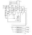
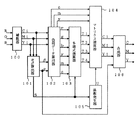
図1はこの発明の一実施形態による色変換方法および色変換装置の構成の一例を示すブロック図である。図において、1は入力された画像データR、G、Bの最大値βと最小値αを算出し、各データを特定する識別符号S1を生成して出力するαβ算出手段、2は画像データR、G、Bと上記αβ算出手段1からの出力より色相データr、g、b、y、m、cを算出する色相データ算出手段、3は多項式演算手段、4はマトリクス演算手段、5は係数発生手段、6は合成手段、15a、15b、15cは、階調特性変換手段である。
【0034】
また、図2は、上記多項式演算手段3の一構成例を示すブロック図である。図において、7は入力された色相データのうちゼロとなるデータを除去するゼロ除去手段、9a、9b、9cは入力されたデータの最小値を選択し出力する最小値選択手段、11は上記αβ算出手段1からの識別符号S1に基づき、演算係数を発生し出力する演算係数発生手段、10a、10bは上記演算係数発生手段11からの出力が示す演算係数と、最小値選択手段9a及び9bの出力との乗算を行う演算手段である。
【0035】
次に動作について説明する。赤、緑、青の三色に対応した入力信号Ri、Gi、Biは、αβ算出手段1および色相データ算出手段2へと送られ、αβ算出手段1は、入力画像データRi、Gi、Biの最大値βと最小値αを算出して出力するとともに、入力画像データRi、Gi、Biのうち最大値となるデータと最小値となるデータを特定する識別符号S1を生成し出力する。色相データ算出手段2は、入力画像データRi、Gi、Biと上記αβ算出手段1からの出力である最大値βと最小値αを入力とし、r=Ri−α、g=Gi−α、b=Bi−αおよびy=β−Bi、m=β−Gi、c=β−Riの減算処理を行い、6つの色相データr、g、b、y、m、cを出力する。
【0036】
このとき、上記αβ算出手段1において算出される最大値β、最小値αは、β=MAX(Ri、Gi、Bi)、α=MIN(Ri、Gi、Bi)であり、色相データ算出手段2において算出される6つの色相データr、g、b、y、m、cは、r=Ri−α、g=Gi−α、b=Bi−αおよびy=β−Bi、m=β−Gi、c=β−Riの減算処理によって得られているので、これら6つの色相データは、この中の少なくとも2つがゼロになる性質がある。例えば、最大値βがRi、最小値αがGiである場合(β=Ri、α=Gi)は、上記の減算処理よりg=0およびc=0となり、また、最大値βがRi、最小値αがBiである場合(β=Ri、α=Bi)は、b=0およびc=0となる。すなわち、最大、最小となるRi、Gi、Biの組み合わせにより、少なくとも、r、g、bの中で1つ、y、m、cの中で1つの合計2つの値がゼロとなることになる。
【0037】
したがって、上記αβ算出手段1においては、6つの色相データのうちゼロとなるデータを特定する識別符号S1を生成し出力する。この識別符号S1は、最大値βと最小値αがRi、Gi、Biのうちどれであるかにより、データを特定する6種類の識別符号S1を生成することができる。図3は識別符号S1とRi、Gi、Biにおける最大値βと最小値αおよびゼロとなる色相データの関係を示す図である。なお、図中の識別符号S1の値はその一例を示すものであり、この限りではなく、他の値であってもよい。
【0038】
次に、色相データ算出手段2からの出力である6つの色相データr、g、bおよびy、m、cは多項式演算手段3へと送られ、また、r、g、bについてはマトリクス演算手段4へも送られる。多項式演算手段3には上記αβ算出手段1から出力される識別符号S1も入力されており、r、g、b中でゼロでない2つのデータQ1、Q2と、y、m、c中でゼロでない2つのデータP1、P2を選択して演算を行うのであるが、この動作を図2に従って説明する。
【0039】
多項式演算手段3において、色相データ算出手段2からの色相データとαβ算出手段からの識別符号S1はゼロ除去手段7へと入力される。ゼロ除去手段7では、識別符号S1に基づき、r、g、b中でゼロでない2つのデータQ1、Q2とy、m、c中でゼロでない2つのデータP1、P2を出力する。Q1、Q2、P1、P2は、例えば図4に示すように決定され、出力される。例えば図3、4から、識別符号S1=0となる場合、r、bからQ1、Q2が、y、mからP1、P2が得られ、Q1=r、Q2=b、P1=m、P2=yとして出力する。なお、上記図3と同様、図4中の識別符号S1の値はその一例を示すものであり、この限りではなく、他の値であってもよい。
【0040】
また、最小値選択手段9aでは、上記ゼロ除去手段7からの出力データQ1、Q2のうちの最小値T4=min(Q1,Q2)を選択して出力し、最小値選択手段9bでは、上記ゼロ除去手段7からの出力データP1、P2のうちの最小値T2=min(P1,P2)を選択して出力する。最小値選択手段9aおよび9bから出力されるT4およびT2が、第1の比較データである。
【0041】
演算係数発生手段11には上記αβ算出手段1からの識別符号S1が入力され、演算手段10a、10bにおいて第1の比較データT4およびT2に対し乗算を行うための演算係数aq、apを示す信号を識別符号S1に基づき発生し、演算手段10aへ演算係数aqを、演算手段10bへは演算係数apを出力する。なお、この演算係数aq、apはそれぞれ識別符号S1に応じて6種類与えられる。演算手段10aでは上記最小値選択手段9aからの第1の比較データT4が入力され、演算係数発生手段11からの演算係数aqと第1の比較データT4による乗算aq×T4を行い、その出力を最小値選択手段9cへ送り、演算手段10bでは上記最小値選択手段9bからの第1の比較データT2が入力され、演算係数発生手段11からの演算係数apと第1の比較データT2による乗算ap×T2を行い、その出力を最小値選択手段9cへ送る。
【0042】
最小値選択手段9cでは、演算手段10aおよび10bからの出力の最小値T5=min(ap×T2、aq×T4)を選択して出力する。最小値選択手段9cから出力されるT5が、第2の比較データである。以上、上述した多項式データT2、T4、T5が、多項式演算手段3の出力である。そして、この多項式演算手段3の出力は演算項としてマトリクス演算手段4へと送られる。
【0043】
一方、図1の係数発生手段5は、識別符号S1に基づき、多項式データの演算係数U(Fij)と固定係数U(Eij)を発生し、マトリクス演算手段4へと送る。マトリクス演算手段4は、上記色相データ算出手段2からの色相データr、g、bと多項式演算手段3からの多項式データT2、T4、T5、係数発生手段5からの係数Uを入力とし、下記の式(6)の演算結果を画像データR1、G1、B1として出力する。
【0044】
【数10】
なお、式(6)において、(Eij)ではi=1〜3、j=1〜3、(Fij)ではi=1〜3、j=1〜3である。
【0046】
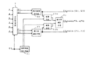
ここで、図5は、上記マトリクス演算手段4における部分的な一構成例を示すブロック図であり、R1を演算し出力する場合について示している。図において、12a、12c、12e、12fは乗算手段、13a、13d、13eは加算手段である。
【0047】
次に、図5の動作を説明する。乗算手段12a、12c、12e、12fは、色相データrと多項式演算手段3からの多項式データT2、T4、T5と係数発生手段5からの係数U(Eij)およびU(Fij)を入力とし、それぞれの積を出力する。加算手段13aは、各乗算手段12c、12eの出力である積を入力とし、入力データを加算し、その和を出力する。加算手段13dは加算手段13aからの出力と乗算手段12fの出力を加算する。そして加算手段13eは加算手段13dの出力と乗算手段12aの出力を加算して、総和を画像データR1として出力する。なお、図5の構成例において、色相データrをgまたはbに置換すれば、画像データG1、B1を演算できる。
【0048】
本実施の形態による色変換方法あるいは、色変換装置の演算速度が問題になる場合には、係数(Eij)と(Fij)は、それぞれの色相データr、g、bに対応した係数が使用されるので、図5の構成をr、g、bに対し並列に3つ使用すれば、より高速なマトリクス演算が可能になる。
【0049】
合成手段6は、上記マトリクス演算手段4からの画像データR1、G1、B1と上記αβ算出手段1からの出力である無彩色データを示す最小値αが入力され、加算を行い、画像データR、G、Bを出力する。よって、上記図1の色変換方法により色変換された画像データR、G、Bを求める演算式は、式(1)となる。
【0050】
【数11】
ここで、(Eij)ではi=1〜3、j=1〜3、(Fij)ではi=1〜3、j=1〜12であり、h1r=min(m、y)、h1g=min(y、c)、h1b=min(c、m)、h1c=min(g、b)、h1m=min(b、r)、h1y=min(r、g)、h2ry=min(aq1×h1y、ap1×h1r)、h2rm=min(aq2×h1m、ap2×h1r)、h2gy=min(aq3×h1y、ap3×h1g)、h2gc=min(aq4×h1c、ap4×h1g)、h2bm=min(aq5×h1m、ap5×h1b)、h2bc=min(aq6×h1c、ap6×h1b)であり、aq1〜aq6およびap1〜ap6は上記図2における演算係数発生手段11において発生される演算係数である。
【0052】
なお、式(1)の演算項と図1における演算項の数の違いは、図1における演算項がゼロとなるデータを除く画素毎の演算方法を開示しているのに対して、式(1)は画素集合に対する一般式を開示している点にある。つまり、式(1)の多項式データは、1画素について、12個のデータを3個の有効データに削減でき、この削減は、色相データの性質を巧みに活用して達成している。
【0053】
また、有効データの組合せは、着目画素の画像データに応じて変わり、全画像データでは全ての多項式データが有効になる。
【0054】
図6(A)〜(F)は、6つの色相(赤、イエロー、緑、シアン、青、マゼンタ)と色相データy、m、c、r、g、bの関係を模式的に示したものであり、各色相データはそれぞれ3つの色相に関与している(例えば、図6(A)に示すyであれば、赤、イエロー、緑の3つの色相に関与する)。
【0055】
上記式(6)と式(1)は、各色相の1つだけに有効な第1の比較データを含んでいる。この第1の比較データは、h1r=min(y,m)、h1y=min(r,g)、h1g=min(c,y)、h1c=min(g,b)、h1b=min(m,c)、h1m=min(b,r)の6つである。図7(A)〜(F)は、6つの色相と第1の比較データh1r、h1y、h1g、h1c、h1b、h1mの関係を模式的に示したものであり、各第1の比較データが特定の色相に関与していることが分かる。
【0056】
例えば、Wを定数として、赤に対してはr=W、g=b=0なので、y=m=W、c=0となる。したがって、min(y,m)=Wとなり、他の5つの第1の比較データは全てゼロになる。つまり、赤に対しては、h1r=min(y,m)のみが有効な第1の比較データになる。同様に、緑にはh1g=min(c,y)、青にはh1b=min(m,c)、シアンにはh1c=min(g,b)、マゼンタにはh1m=min(b,r)、イエローにはh1y=min(r,g)だけが有効な第1の比較データとなる。
【0057】
図8(A)〜(F)は、6つの色相と、第2の比較データh2ry=min(h1y,h1r)、h2gy=min(h1y,h1g)、h2gc=min(h1c,h1g)、h2bc=min(h1c,h1b)、h2bm=min(h1m,h1b)、h2rm=min(h1m,h1r)の関係を模式的に示したものであり、上記式(1)でのh2ry=min(aq1×h1y、ap1×h1r)、h2gy=min(aq3×h1y、ap3×h1g)、h2gc=min(aq4×h1c、ap4×h1g)、h2bc=min(aq6×h1c、ap6×h1b)、h2bm=min(aq5×h1m、ap5×h1b)、h2rm=min(aq2×h1m、ap2×h1r)における演算係数aq1〜aq6およびap1〜ap6の値を1とした場合について示している。図9のそれぞれより、各第2の比較データが赤〜イエロー、イエロー〜緑、緑〜シアン、シアン〜青、青〜マゼンタ、マゼンタ〜赤の6つの色相間の中間領域の変化に関与していることが分かる。つまり、赤〜イエローに対しては、b=c=0であり、h2ry=min(h1y,h1r)=min(min(r,g),min(y、m))を除く他の5項は全てゼロになる。よって、h2ryのみが有効な第2の比較データになり、同様に、イエロー〜緑にはh2gy、緑〜シアンにはh2gc、シアン〜青にはh2bc、青〜マゼンタにはh2bm、マゼンタ〜赤にはh2rmだけが有効な第2の比較データとなる。
【0058】
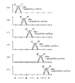
また、図9(A)〜(F)は上記式(6)および式(1)でのhry、hrm、hgy、hgc、hbm、hbcにおける演算係数aq1〜aq6およびap1〜ap6を変化させた場合の6つの色相と第2の比較データの関係を模式的に示したものであり、図中の破線a1〜a6で示す場合は、aq1〜aq6をap1〜ap6より大きい値とした場合の特性を示し、破線b1〜b6で示す場合は、ap1〜ap6をaq1〜aq6より大きい値とした場合の特性を示している。
【0059】
すなわち、赤〜イエローに対してはh2ry=min(aq1×h1y,ap1×h1r)のみが有効な第2の比較データであるが、例えばaq1とap1の比を2:1とすると、図9(A)での破線a1のように、ピーク値が赤よりに関与する比較データとなり、赤〜イエローの色相間における赤に近い領域に有効な比較データとすることができる。一方、例えばaq1とap1の比を1:2とすると、図9(A)での破線b1のような関係となり、ピーク値がイエローよりに関与する比較データとなり、赤〜イエローの色相間におけるイエローに近い領域に有効な比較データとすることができる。同様に、イエロー〜緑にはh2gyにおけるaq3、ap3を、緑〜シアンにはh2gcにおけるaq4、ap4を、シアン〜青にはh2bcにおけるaq6、ap6を、青〜マゼンタにはh2bmにおけるaq5、ap5を、マゼンタ〜赤にはh2rmにおけるaq2、ap2を変化させることにより、それぞれの色相間の領域においても、その有効となる領域を変化させることができる。
【0060】
図10(a)および(b)は、6つの色相および色相間領域と有効な演算項の関係を示している。よって、係数発生手段5において、調整したい色相または色相間の領域に有効な演算項に係わる係数を変化させれば、その着目する色相のみを調整でき、色相間の変化の度合いをも補正することができる。また、多項式演算手段3における演算係数発生手段11での係数を変化させれば、色相間領域での演算項が有効となる領域を他の色相に影響することなく変化させることができる。
【0061】
ここで、上記図1による実施の形態1での係数発生手段5での係数の一例を述べる。式(5)は、上記係数発生手段5において発生する係数U(Eij)の一例を示している。
【0062】
【数12】
上記の場合で係数U(Fij)の係数を全てゼロとすると、色変換を実施しない場合となる。また、下記式(7)では、係数U(Fij)の係数において、第1の比較データと第2の比較データに係わる係数を例えばAr1〜Ar3、Ay1〜Ay3、Ag1〜Ag3、Ac1〜Ac3、Ab1〜Ab3、Am1〜Am3、およびAry1〜Ary3、Agy1〜Agy3、Agc1〜Agc3、Abc1〜Abc3、Abm1〜Abm3、Arm1〜Arm3に示す値とした場合を示す。
【0064】
【数13】
上記においては、色相または、色相間の領域のみの調整を行え、変化させたい色相または色相間の領域に関する演算項に係わる係数を定め、他の係数をゼロとすれば、その色相または色相間の領域のみの調整を行える。例えば、赤に関するh1rに係わる係数Ar1〜
Ar3を設定すれば、赤の色相を変化させ、赤〜イエローの色相間の割合を変化させるにはh2ryに係わる係数Ary1〜Ary3を用いることとなる。
【0066】
また、多項式演算手段3において、h2ry=min(aq1×h1y、ap1×h1r)、h2rm=min(aq2×h1m、ap2×h1r)、h2gy=min(aq3×h1y、ap3×h1g)、h2gc=min(aq4×h1c、ap4×h1g)、h2bm=min(aq5×h1m、ap5×h1b)、h2bc=min(aq6×h1c、ap6×h1b)における演算係数aq1〜aq6およびap1〜ap6の値を1、2、4、8、…の整数値で変化させれば、演算手段10aおよび10bにおいてビットシフトにより乗算を行うことができる。
【0067】
以上より、特定の色相に関与する第1の比較データおよび第2の比較データに係る係数を変化させることにより、係数U(Fij)の係数を独立に補正して、上記6つの色相間の変化の度合いをも補正できる。さらに階調特性変換手段15a、15b、15cにより階調特性変換することにより、2次より高次な非線形性あるいは、1次的な演算あるいは、2次的な演算の組み合わせでは、得ることのできない、例えば、液晶の有するようなS字特性など複雑な非線形特性をも補正することができる。よって、変換特性を柔軟に変更できて、しかも大容量メモリを必要としない色変換方法または色変換装置を得ることができる。ここで、階調特性変換手段は、1次元ルックアップテーブルなどにより実現可能であり、その規模は、3次元ルックアップテーブルと比較した場合、はるかに小さいことは、言うまでも無い。
【0068】
なお、上記実施の形態1では、入力画像データR、G、Bをもとに色相データr、g、bおよびy、m、cと最大値β、最小値αを算出して各色相に係わる演算項を得て、マトリクス演算後、画像データR、G、Bを得る場合として説明したが、上記出力画像データR、G、Bを得た後、
R、G、Bを補色データC、M、Yに変換してもよく、上記と同様の効果を奏する。
【0069】
また、上記実施の形態1では、ハードウェアにより図1の構成の処理を行う場合について説明しているが、ソフトウェアなどにより同様の処理を行う色変換方法としても効果的であることは言うまでもなく、上記実施の形態1と同様の効果を奏する。また、階調特性変換手段15a、15b、15cそれぞれの変換特性は、出力デバイスの特性を考慮して決められるもので、例えばガンマ補正特性などに限定されるものではなく、極端な場合には、直線的な特性のものであっても良い。ただし、直線的な場合であっても、その傾きを個々に変えることにより出力信号のレベルバランスを調整することも可能である。
【0070】
さらに、上記式(5)、式(7)に示す係数を用いた場合の色変換装置の動作について述べる。図11乃至13は、実施の形態1の色変換装置における動作を説明するためのxy色度図である。ここで、xy色度図は、分光情報からの演算によって求められる2つの値、xおよびyを用いて、色の持つ情報を2次元のグラフ上に表したものであり、画像再生装置1における色再現を、目標とする色再現と共に示したものである。
【0071】
図において、実線は画像再生装置1における色再現(画像再生装置1において再現可能な色の範囲)を表し、点線は目標とする色再現(目標とする色再現において再現可能な色の範囲)を表す。ここで、画像再生装置1としては、モニター等の表示装置が考えられる。また、目標とする色再現としては、他の種類の表示装置や、理論上または仮想的な色再現等が考えられる。
【0072】
図11に示した例による、画像再生装置1において再現可能な色の範囲は、目標とする色再現において再現可能な色の範囲より狭い場合のものであり、色再現を表す三角形の中央付近より、三角形の頂点、および辺に向かって伸びている直線の方向は、それぞれの色の色相を表す。
【0073】
図11の例においては、画像再生装置1における色再現と、目標とする色再現においては、それぞれの三角形の中央付近より、三角形の頂点、および辺に向かって伸びている直線の方向は一致していない。このことは、それぞれにおいて再現される色相が一致していないことを表す。
【0074】
実施の形態1の色変換装置は、6つの色相のそれぞれに対して有効な第1の比較データと、上記色相間領域のそれぞれに対して有効な第2の比較データを持つ。
【0075】
図12は、実施の形態1の色変換装置において、第1の比較データに係わる係数の値を調整することにより、画像再生装置1における色再現と、目標とする色再現において再現される色相を一致させた場合を表す色度図である。
【0076】
図12において、実線および破線は、画像再生装置1における色再現を表し、実線は第1の比較データに係わる係数の値を調整した場合の色再現を表し、破線は第1の比較データに係わる係数の値を調整しない場合の色再現を表す。また、点線は目標とする色再現を表す。
【0077】
図12の例においては、実施の形態1の色変換装置における第1の比較データに係わる係数の値を調整することにより、画像再生装置1における色再現は、目標とする色再現において再現される色相と一致している。しかし、第1の比較データに係わる係数の値を調整した場合の色再現範囲は、第1の比較データに係わる係数の値を調整しない場合の色再現範囲よりも狭くなっている。
【0078】
図13は実施の形態1の色変換装置において、第1の比較データに係わる係数のみならず、第2の比較データに係わる係数の値を調整した場合の画像再生装置1における色再現と、目標とする色再現を表す色度図である。
【0079】
図13の例においては、第1の比較データおよび第2の比較データに係わる係数の値をともに調整することにより、画像再生装置1における色再現は、目標とする色再現において再現される色相と一致しており、さらに、第1の比較データおよび第2の比較データに係わる係数の値を調整した場合の色再現範囲は、第1の比較データおよび第2の比較データに係わる係数の値を調整しない場合の色再現範囲を維持している。
【0080】
すなわち、実施の形態1の色変換装置において、第1の比較データおよび第2の比較データに係わる係数の値を調整することにより、色再現範囲を狭めることなく、色相調整が可能となる。
【0081】
実施の形態2.
実施の形態1では、入力画像データR、G、Bをもとに色相データr、g、bおよびy、m、cと最大値β、最小値αを算出して各色相に係わる演算項を得て、マトリクス演算後、画像データR、G、Bを得る場合として説明したが、入力画像データR、G、Bを補色データC、M、Yに変換後、入力を補色データC、M、Yとして色変換を行うように構成することもできる。
【0082】
図14はこの発明の実施形態2による色変換方法および色変換装置の構成の一例を示すブロック図である。図において、3、4、5、6、15a、15b、15cは上記実施の形態1の図1におけるものと同一のものであり、14は補数手段、1bは補色データの最大値βと最小値αおよび色相データを特定するための識別符号S1を生成するαβ算出手段、2bは上記補数手段14からの補色データC、M、Yとαβ算出手段1bからの出力より色相データr、g、b、y、m、cを算出する色相データ算出手段である。
【0083】
次に、動作を説明する。補数手段14は、画像データR、G、Bを入力とし、1の補数処理した補色データCi、Mi、Yiを出力する。αβ算出手段1bでは、この補色データの最大値βと最小値αおよび各色相データを特定するための識別符号S1を出力する。
【0084】
色相データ算出手段2bは、補色データCi、Mi、Yiと上記αβ算出手段1bからの最大値βと最小値αを入力とし、r=β−Ci、g=β−Mi、b=β−Yiおよびy=Yi−α、m=Mi−α、c=Ci−αの減算処理によって、6つの色相データr、g、b、y、m、cを出力する。ここで、これら6つの色相データは、この中の少なくとも2つがゼロになる性質があり、上記αβ算出手段1bから出力される識別符号S1は、6つの色相データのうちゼロとなるデータを特定するものであり、最大値βと最小値αがCi、Mi、Yiのうちどれであるかにより、データを特定する6種類の識別符号となる。この6つの色相データのうちゼロとなるデータと識別符号S1との関係は上記実施の形態1での説明と同様であるので、詳細な説明は省略する。
【0085】
次に、色相データ算出手段2bからの出力である6つの色相データr、g、bおよびy、m、cは多項式演算手段3へと送られ、また、c、m、yについてはマトリクス演算手段4へも送られる。多項式演算手段3には上記αβ算出手段1bから出力される識別符号S1も入力されており、r、g、b中でゼロでない2つのデータQ1、Q2と、y、m、c中でゼロでない2つのデータP1、P2を選択して演算を行うのであるが、この動作は上記実施の形態1における図2の動作と同一であるので、その詳細な説明は省略する。
【0086】
そして、この多項式演算手段3の出力はマトリクス演算手段4へと送られ、係数発生手段5は、識別符号S1に基づき、多項式データの演算係数U(Fij)と固定係数U(Eij)を発生し、マトリクス演算手段4へと送る。マトリクス演算手段4は、上記色相データ算出手段2bからの色相データc、m、yと多項式演算手段3からの多項式データT2、T4、T5、係数発生手段5からの係数Uを入力とし、下記の式(8)の演算結果を画像データC1、M1、Y1として出力する。
【0087】
【数14】
なお、式(8)において(Eij)ではi=1〜3、j=1〜3、(Fij)ではi=1〜3、j=1〜3である。
【0089】
なお、マトリクス演算手段4における動作は、上記実施の形態1における図5において、入力される色相データをc(またはm、y)とし、C1(またはM1、Y1)を演算し出力する場合であり、同様の動作を行うので、その詳細な説明は省略する。
【0090】
合成手段6は、上記マトリクス演算手段4からの補色データC1、M1、Y1と上記αβ算出手段1bからの出力である無彩色データを示す最小値αが入力され、加算を行い、画像データC、M、Yを出力する。よって、上記図14の色変換方法により色変換された画像データC、M、Yを求める演算式は、式(2)となる。
【0091】
【数15】
ここで、式(2)において(Eij)ではi=1〜3、j=1〜3、(Fij)ではi=1〜3、j=1〜12であり、h1r=min(m、y)、h1g=min(y、c)、h1b=min(c、m)、h1c=min(g、b)、h1m=min(b、r)、h1y=min(r、g)、h2ry=min(aq1×h1y、ap1×h1r)、h2rm=min(aq2×h1m、ap2×h1r)、h2gy=min(aq3×h1y、ap3×h1g)、h2gc=min(aq4×h1c、ap4×h1g)、h2bm=min(aq5×h1m、ap5×h1b)、h2bc=min(aq6×h1c、ap6×h1b)であり、aq1〜aq6およびap1〜ap6は上記図2における演算係数発生手段11において発生される演算係数である。
【0093】
なお、式(2)の演算項と図14における演算項の数の違いは、図14における演算項がゼロとなるデータを除く画素毎の演算方法を開示しているのに対して、式(2)は画素集合に対する一般式を開示している点にある。つまり、式(2)の多項式データは、1画素について、12個のデータを3個の有効データに削減でき、この削減は、色相データの性質を巧みに活用して達成している。
【0094】
また、有効データの組合せは、着目画素の画像データに応じて変わり、全画像データでは全ての多項式データが有効になる。
【0095】
そして、上記式(2)の多項式演算手段による演算項は、実施の形態1における式(1)の演算項と同一であり、したがって、6つの色相および色相間領域と有効な演算項の関係は図10(a)および(b)に示す場合と同一となる。よって、実施の形態1と同様、係数発生手段5において、調整したい色相または色相間の領域に有効な演算項に係わる係数を変化させれば、その着目する色相のみを調整でき、色相間の変化の度合いをも補正することができる。また、多項式演算手段3における演算係数発生手段11での係数を変化させれば、色相間領域での演算項が有効となる領域を他の色相に影響することなく変化させることができる。
【0096】
ここで、上記実施の形態2での係数発生手段5での係数の一例としては、上記実施の形態1の場合と同様、式(5)による係数U(Eij)となり、係数U(Fij)の係数を全てゼロとすると、色変換を実施しない場合となる。また、式(7)に示す係数U(Fij)の係数において、第1の比較データと第2の比較データに係わる係数により補正を行うことで、色相または色相間の領域のみの調整を行え、変化させたい色相または色相間の領域に関する演算項に係わる係数を定め、他の係数をゼロとすれば、その色相または色相間の領域のみの調整を行える。
【0097】
以上より、特定の色相に関与する第1の比較データに係る係数を変化させることにより、赤、青、緑、イエロー、シアン、マゼンタの6つの色相において着目している色相のみを、他の色相に影響を与えることなく調整でき、更に、第2の比較データに係る係数を変化させることにより、赤〜イエロー、イエロー〜緑、緑〜シアン、シアン〜青、青〜マゼンタ、マゼンタ〜赤の6つの色相間の領域を独立に補正して、上記6つの色相間の変化の度合いをも補正できる。さらに階調特性変換手段15a、15b、15cにより階調特性変換することにより、2次より高次な非線形性あるいは、1次的な演算あるいは、2次的な演算の組み合わせでは、得ることのできない、例えば、液晶の有するようなS字特性など複雑な非線形特性をも補正することができる。よって、変換特性を柔軟に変更できて、しかも大容量メモリを必要としない色変換方法または色変換装置を得ることができる。ここで、階調特性変換手段は、1次元ルックアップテーブルなどにより実現可能であり、その規模は、3次元ルックアップテーブルと比較した場合、はるかに小さいことは、言うまでも無い。
【0098】
なお、上記実施の形態2では、ハードウェアにより図15の構成の処理を行う場合について説明しているが、ソフトウェアなどにより同様の処理を行う色変換方法としても効果的であることは言うまでもなく、上記実施の形態2と同様の効果を奏する。また、階調特性変換手段15a、15b、15cそれぞれの変換特性は、出力デバイスの特性を考慮して決められるもので、例えばガンマ補正特性などに限定されるものではなく、極端な場合には、直線的な特性のものであっても良い。ただし、直線的な場合であっても、その傾きを個々に変えることにより出力信号のレベルバランスを調整することも可能である。
【0099】
実施の形態3.
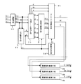
実施の形態1ではマトリクス演算手段4における部分的な一構成例を図5に示すブロック図であるとし、式(1)に示すように、色相データと各演算項および無彩色データであるR、G、Bの最小値αを加算して画像データR、G、Bを出力するよう構成したが、図15に示すように、係数発生手段において無彩色データである最小値αに対する係数を発生することにより、無彩色成分を調整するよう構成することもできる。
【0100】
図15はこの発明の実施形態3による色変換方法および色変換装置の構成の一例を示すブロック図である。図において、1、2、3、15a、15b、15cは上記実施の形態1の図1におけるものと同一のものであり、4bはマトリクス演算手段、5bは係数発生手段である。
【0101】
次に動作を説明する。入力データよりαβ算出手段1において最大値β、最小値αおよび識別符号S1を求め、色相データ算出手段2により6つの色相データを算出し、多項式演算手段3において演算項を求める動作は上記実施の形態1と同一であるのでその詳細な説明は省略する。
【0102】
図15の係数発生手段5bは、識別符号S1に基づき、多項式データの演算係数U(Fij)と固定係数U(Eij)を発生し、マトリクス演算手段4bへと送る。マトリクス演算手段4bは、上記色相データ算出手段2からの色相データr、g、bと多項式演算手段3からの多項式データT2、T4、T5、αβ算出手段1からの最小値αおよび係数発生手段5bからの係数Uを入力とし、演算を行うのであるが、その演算式は下記の式(9)を使用し、無彩色成分を調整する。
【0103】
【数16】
なお、式(9)において(Eij)ではi=1〜3、j=1〜3、(Fij)ではi=1〜3、j=1〜4である。
【0105】
ここで、図16はマトリクス演算手段4bの部分的な構成例を示すブロック図であり、図16において、12a、12c、12e、12f、13a、13d、13eは上記実施の形態1でのマトリクス演算手段4と同一のものであり、12gは図1におけるαβ算出手段1からの無彩色成分を示す最小値αと係数発生手段5bからの係数Uを入力とし、その乗算を行う乗算手段、13fは加算手段である。
【0106】
次に、図16の動作を説明する。乗算手段12a、12c、12e、12fは、色相データrと多項式演算手段3からの多項式データT2、T4、T5と係数発生手段5bからの係数U(Eij)およびU(Fij)を入力とし、それぞれの積を出力し、加算手段13a、13d、13eにおいて、それぞれの積および和を加算するのであるが、その動作は実施の形態1におけるマトリクス演算手段4での動作と同一である。乗算手段12gには、αβ算出手段1からの無彩色成分に相当するR、G、Bデータの最小値αと係数発生手段5bからの係数U(Fij)が入力されて乗算を行い、その積を加算手段13fへと出力し、加算手段13fで上記加算手段13eからの出力と加算して、総和を画像データRの出力Rとして出力する。なお、図17の構成例において、色相データrをgまたはbに置換すれば、画像データG、Bを演算できる。
【0107】
ここで、係数(Eij)と(Fij)は、それぞれの色相データr、g、bに対応した係数が使用され、図17の構成をr、g、bに対し並列に3つ使用すれば、高速なマトリクス演算が可能になる。
【0108】
以上より、マトリクス演算手段4bは各演算項および無彩色データである最小値αに対し係数により演算を行い、色相データと加算して画像データR、G、Bを出力し、このときの画像データを求める演算式は、式(3)となる。
【0109】
【数17】
ここで、式(3)において(Eij)ではi=1〜3、j=1〜3、(Fij)i=1〜3、j=1〜13である。
【0111】
なお、式(3)の演算項と図15での演算項の数の違いは、上記実施の形態1の場合と同様に、図15の多項式データ演算手段における演算項がゼロとなるデータを除く画素毎の演算方法を開示しているのに対して、式(3)は画素集合に対する一般式を開示している点にある。つまり、式(3)の多項式データは、1画素について、13個のデータを4個の有効データに削減でき、この削減は、色相データの性質を巧みに活用して達成している。
【0112】
また、有効データの組合せは、着目画素の画像データに応じて変わり、全画像データでは全ての多項式データが有効になる。
【0113】
ここで、上記最小値αに係わる係数を全て1とすると、無彩色データは変換されず、入力データにおける無彩色データと同一の値となる。そして、マトリクス演算において係数を変化させれば、赤みの黒、青みの黒等の選択ができ、無彩色成分を調整できる。
【0114】
以上より、特定の色相に関与する第1の比較データと、色相間領域に関与する第2の比較データそれぞれに係る係数を変化させることにより、赤、青、緑、イエロー、シアン、マゼンタの6つの色相および6つの色相間領域において着目している色相のみを、他の色相に影響を与えることなく調整できるのみならす、無彩色データである最小値αに係わる係数を変化させることにより、無彩色成分のみのを色相成分に影響を与えることなく調整することができ、例えば標準の黒、赤みの黒、青みの黒等の選択を行うことができる。
【0115】
なお、上記実施の形態3では、マトリクス演算後画像データR、G、Bを得る場合として説明したが、上記出力画像データR、G、Bを得た後、
R、G、Bを補色データC、M、Yに変換してもよく、マトリクス演算における係数を各色相および色相間領域と無彩色データである最小値αに対して変化できれば、上記と同様の効果を奏する。
【0116】
また、上記実施の形態1と同様、実施の形態3においても、ソフトウェアなどにより同様の処理を行う色変換方法としても効果的であることは言うまでもなく、上記実施の形態3と同様の効果を奏する。また、階調特性変換手段15a、15b、15cそれぞれの変換特性は、出力デバイスの特性を考慮して決められるもので、例えばガンマ補正特性などに限定されるものではなく、極端な場合には、直線的な特性のものであっても良い。ただし、直線的な場合であっても、その傾きを個々に変えることにより出力信号のレベルバランスを調整することも可能である。
【0117】
実施の形態4.
実施の形態2では式(2)に示すように、色相データと各演算項および無彩色データである最小値αを加算するよう構成したが、図17に示すように、係数発生手段において無彩色データである最小値αに対する係数を発生することにより、無彩色成分を調整するよう構成することもできる。
【0118】
図17はこの発明の実施形態4による色変換方法および色変換装置の構成の一例を示すブロック図である。図において、14、1b、2b、3、15a、15b、15cは上記実施の形態2の図14におけるものと同一のものであり、4b、5bは上記実施の形態3の図15におけるものと同一のものである。
【0119】
次に動作を説明する。入力画像データR、G、Bは補数手段14に入力され、1の補数処理した補色データCi、Mi、Yiが出力され、αβ算出手段1bで最大値β、最小値αおよび識別符号S1を求め、色相データ算出手段2bにより6つの色相データを算出し、多項式演算手段3において演算項を求める動作は上記実施の形態2の補色データC、M、Yの場合の処理と同一であるので、その詳細な説明は省略する。
【0120】
図17の係数発生手段5bは、識別符号S1に基づき、多項式データの演算係数U(Fij)と固定係数U(Eij)を発生し、マトリクス演算手段4bへと送る。マトリクス演算手段4bは、上記色相データ算出手段2bからの色相データc、m、yと多項式演算手段3からの多項式データT2、T4、T5、αβ算出手段1bからの最小値αおよび係数発生手段5bからの係数Uを入力とし、演算を行うのであるが、その演算式は下記の式(10)を使用し、無彩色成分を調整する。
【0121】
【数18】
なお、式(10)において(Eij)ではi=1〜3、j=1〜3、(Fij)ではi=1〜3、j=1〜4である。
【0123】
なお、マトリクス演算手段4bにおける動作は、上記実施の形態3における図16において、入力される色相データをc(またはm、y)とし、C(またはM、Y)を演算し出力する場合であり、同様の動作を行うので、その詳細な説明は省略する。
【0124】
以上より、マトリクス演算手段4bは各演算項および無彩色データである最小値αに対し係数により演算を行い、色相データと加算して補色データC、M、Yを出力し、このときの画像データを求める演算式は、式(4)となる。
【0125】
【数19】
ここで、式(4)において(Eij)ではi=1〜3、j=1〜3、(Fij)i=1〜3、j=1〜13である。
【0127】
なお、式(4)の演算項と図17での演算項の数の違いは、上記実施の形態2の場合と同様に、図17の多項式データ演算手段における演算項がゼロとなるデータを除く画素毎の演算方法を開示しているのに対して、式(4)は画素集合に対する一般式を開示している点にある。つまり、式(4)の多項式データは、1画素について、13個のデータを4個の有効データに削減でき、この削減は、色相データの性質を巧みに活用して達成している。
【0128】
また、有効データの組合せは、着目画素の画像データに応じて変わり、全画像データでは全ての多項式データが有効になる。
【0129】
ここで、上記最小値αに係わる係数を全て1とすると、無彩色データは変換されず、入力データにおける無彩色データと同一の値となる。そして、マトリクス演算において係数を変化させれば、赤みの黒、青みの黒等の選択ができ、無彩色成分を調整できる。
【0130】
以上より、特定の色相に関与する第1の比較データと、色相間領域に関与する第2の比較データそれぞれに係る係数を変化させることにより、赤、青、緑、イエロー、シアン、マゼンタの6つの色相および6つの色相間領域において着目している色相のみを、他の色相に影響を与えることなく調整できるのみならす、無彩色データである最小値αに係わる係数を変化させることにより、無彩色成分のみのを色相成分に影響を与えることなく調整することができ、例えば標準の黒、赤みの黒、青みの黒等の選択を行うことができる。
【0131】
また、上記実施の形態と同様、実施の形態4においても、ソフトウェアなどにより同様の処理を行う色変換方法としても効果的であることは言うまでもなく、上記実施の形態4と同様の効果を奏する。また、階調特性変換手段15a、15b、15cそれぞれの変換特性は、出力デバイスの特性を考慮して決められるもので、例えばガンマ補正特性などに限定されるものではなく、極端な場合には、直線的な特性のものであっても良い。ただし、直線的な場合であっても、その傾きを個々に変えることにより入力信号のレベルバランスを調整することも可能である。
【0132】
【発明の効果】
本発明に係る色変換装置および色変換方法によれば、第1の色データから赤、緑、または青の色相に有効な第1の演算項、およびイエロー、マゼンタ、またはシアンの色相に有効な第2の演算項、ならびに赤、イエロー、緑、シアン、青、マゼンタの互いに隣接する2つの色相間内の領域に有効な第3の演算項を生成し、これらの演算項を用いたマトリクス演算により第2の色データを求め、さらに第2の色データの階調を補正するので、上記6つの色相、および色相間内の色成分を独立に調整するとともに、当該第2の色データを表示する表示デバイスの非線形特性を補正することができる。
【図面の簡単な説明】
【図1】この発明の実施の形態1による色変換装置の構成の一例を示すブロック図である。
【図2】この発明の実施の形態1による色変換装置における多項式演算手段3の構成の一例を示すブロック図である。
【図3】この発明の実施の形態1による色変換装置における識別符号S1と最大値βおよび最小値α、0となる色相データの関係の一例を示す図である。
【図4】この発明の実施の形態1による色変換装置における多項式演算手段3のゼロ除去手段7の動作を説明するための図である。
【図5】この発明の実施の形態1による色変換装置におけるマトリクス演算手段4の一部分の構成の一例を示すブロック図である。
【図6】6つの色相と色相データの関係を模式的に示した図である。
【図7】この発明の実施の形態1による色変換装置における第1の比較データと色相の関係を模式的に示した図である。
【図8】この発明の実施の形態1による色変換装置における第2の比較データと色相の関係を模式的に示した図である。
【図9】この発明の実施の形態1による色変換装置における多項式演算手段3の演算係数発生手段11において、演算係数を変化させた場合の比較データによる演算項と色相の関係を模式的に示した図である。
【図10】この発明の実施の形態1による色変換装置において各色相および色相間の領域に関与し、有効となる演算項の関係を示した図である。
【図11】この発明の実施の形態1による色変換装置における動作を説明するためのxy色度図である。
【図12】この発明の実施の形態1による色変換装置における動作を説明するためのxy色度図である。
【図13】この発明の実施の形態1による色変換装置における動作を説明するためのxy色度図である。
【図14】この発明の実施の形態2による色変換装置の構成の一例を示すブロック図である。
【図15】この発明の実施の形態3による色変換装置の構成の一例を示すブロック図である。
【図16】この発明の実施の形態3による色変換装置におけるマトリクス演算手段4bの一部分の構成の一例を示す図である。
【図17】この発明の実施の形態4による色変換装置の構成の一例を示すブロック図である。
【図18】従来の色変換装置の構成の一例を示すブロック図である。
【図19】従来の色変換装置における6つの色相と色相データの関係を模式的に示した図である。
【図20】従来の色変換装置におけるマトリクス演算器104での乗算項と色相の関係を模式的に示した図である。
【符号の説明】
1、1b αβ算出手段、 2、2b 色相データ算出手段、 3 多項式演算手段、 4、4b マトリクス演算手段、 5、5b 係数発生手段、 6 合成手段、 7 ゼロ除去手段、 9a、9b、9c 最小値選択手段、 10a、10b 演算手段、 11 演算係数発生手段、 12a、12c、12e、12f、12g 乗算手段、 13a、13d、13e、13f 加算手段、 14 補数手段、 15a、15b、15c 階調特性変換手段、 100 補数器、 101 αβ算出器、 102 色相データ算出器、 103 多項式演算器、 104 マトリクス演算器、 105 係数発生器、 106 合成器。[0001]
TECHNICAL FIELD OF THE INVENTION
The present invention relates to data processing for use in full-color printing-related devices such as printers, video printers, and scanners, image processing devices for creating computer graphics images, and display devices such as monitors. The present invention relates to a color conversion method and apparatus for performing color conversion processing on image data expressed in three colors according to a device to be used.
[0002]
[Prior art]
Color conversion in printing is an indispensable technique for correcting image quality deterioration caused by color mixing and non-linearity of printing due to non-pure color of an ink, and outputting a print image having good color reproducibility. Also, in a display device such as a monitor, when an input color signal is displayed, a color conversion process is performed in order to output (display) an image having desired color reproducibility in accordance with use conditions and the like.
[0003]
Conventionally, there are two types of color conversion methods in the above case, a table conversion method and a matrix operation method.
[0004]
A typical example of the table conversion method is a three-dimensional lookup table method. In this method, image data expressed in red, green, and blue (hereinafter, referred to as “R, G, B”) is input. And R, G, and B image data or complementary color data of yellow, magenta, and cyan (hereinafter, referred to as “Y, M, C”) stored in a memory such as a ROM. Since conversion characteristics can be adopted, there is an advantage that color conversion with excellent color reproducibility can be executed.
[0005]
However, a simple configuration in which data is stored for each combination of image data results in a large-capacity memory of about 400 Mbit. For example, Japanese Patent Application Laid-Open No. Sho 63-227181 discloses a method of compressing the memory capacity, but it still has about 5 Mbits. Therefore, this method requires a large-capacity memory for each conversion characteristic, and thus has a problem that it is difficult to implement an LSI and a problem that it cannot flexibly cope with changes in use conditions and the like.
[0006]
On the other hand, in the matrix operation method, for example, when print data of Y, M, and C is obtained from image data of R, G, and B, the following expression (27) is a basic operation expression.
[0007]
(Equation 6)
Here, i = 1 to 3 and j = 1 to 3.
[0009]
However, with the simple linear operation of Expression (27), good conversion characteristics cannot be realized due to non-linearity such as printing.
[0010]
A method for improving the above conversion characteristics is disclosed in Japanese Patent Publication No. Hei 2-330226, which employs a matrix operation expression of the following expression (28).
[0011]
(Equation 7)
Here, N is a constant, i = 1 to 3 and j = 1 to 10.
[0013]
Since the equation (28) directly uses image data in which an achromatic component and a color component coexist, mutual interference of calculations occurs. That is, if one coefficient is changed, it affects not only the component or the hue of interest but also a problem that good conversion characteristics cannot be realized.
[0014]
A color conversion method disclosed in Japanese Patent Application Laid-Open No. 7-170404 discloses this solution. FIG. 18 is a block circuit diagram showing a color conversion method for converting R, G, B image data into print data C, M, Y in JP-A-7-170404, where 100 is a complementer and 101 is
[0015]
Next, the operation will be described. The complementer 100 receives the image data R, G, and B as input, and outputs complementary color data Ci, Mi, and Yi that have been subjected to one's complement processing. The αβ calculator 101 outputs a maximum value β and a minimum value α of the complementary color data and an identification code S for specifying each data.
[0016]
The
[0017]
The polynomial calculator 103 receives the hue data and the identification code as inputs, and selects two non-zero data Q1, Q2 in r, g, b and two non-zero data P1, P2 in y, m, c. , And calculates and outputs polynomial data T1 = P1 × P2, T3 = Q1 × Q2, T2 = T1 / (P1 + P2), and T4 = T2 / (Q1 + Q2).
In the following description, an asterisk (*) in the figure may be used to represent the product.
[0018]
The
[0019]
(Equation 8)
The synthesizer 106 adds the color ink data C1, M1, and Y1 to the achromatic data α, and outputs print data C, M, and Y. Therefore, the operation expression for obtaining the print data is Expression (30).
[0021]
(Equation 9)
Expression (30) discloses a general expression for a pixel set.
[0023]
Here, FIGS. 19A to 19F show six hues and hue data of red (R), blue (G), green (B), yellow (Y), cyan (C), and magenta (M). FIG. 5 is a diagram schematically illustrating a relationship among y, m, c, r, g, and b, and each hue data is related to three hues. FIGS. 20A to 20F schematically show the relationship between the above six hues and the multiplication terms y × m, r × g, c × y, g × b, m × c, and b × r. It can be seen that each is related to a specific hue among the six hues.
[0024]
Therefore, the six multiplication terms y × m, m × c, c × y, r × g, g × b, and b × r in equation (30) are the six of red, blue, green, yellow, cyan, and magenta, respectively. Of only one of the hues, ie, y × m for red, m × c for blue, c × y for green, r × g for yellow, Only g × b for cyan and b × r for magenta are effective multiplication terms.
[0025]
Also, the six multiplication / division terms y × m / (y + m), m × c / (m + c), c × y / (c + y), r × g / (r + g), and g × b / (g + b) in equation (30) ) And b × r / (b + r) also involve only a specific hue among the six hues.
[0026]
As described above, according to the color conversion method in FIG. 18 described above, by changing the coefficients related to the multiplication term and the multiplication / division term related to a specific hue, only the focused hue affects other hues. Without any adjustments.
[0027]
The above multiplication term is a secondary operation with respect to saturation, and the multiplication / division term is a primary operation with respect to saturation. Therefore, by using both the multiplication term and the multiplication / division term, it is possible to correct non-linearity such as printing on the saturation.
[0028]
However, also in this color conversion method, if it is desired to enlarge or reduce the area occupied in the color space of a specific hue according to preference, specifically, in a color space that changes from magenta to red to yellow, This requirement cannot be satisfied when it is desired to enlarge or reduce the area occupied by.
[0029]
[Problems to be solved by the invention]
When the conventional color conversion method or color conversion device is configured by a three-dimensional lookup table conversion method using a memory such as a ROM, a large-capacity memory is required, and the conversion characteristics cannot be flexibly changed. There is a problem, and in the case of a matrix operation method, only the hue of interest can be adjusted, but the degree of change among the six hues of red, blue, green, yellow, cyan, and magenta cannot be corrected. In addition, there is a problem that good conversion characteristics cannot be realized in all color spaces. Further, a color conversion method using a matrix system shown in FIG. 19 or a display device is, for example, a printing device, a cathode ray tube display device, or a liquid crystal display device. If the output expressed in terms of reflectance or luminance has nonlinear tone characteristics, as in UNA at most 1
Good conversion characteristics could not be obtained, for example, with respect to complicated gradation characteristics such as the S-characteristics of a liquid crystal display device only by a combination of a secondary operation and a secondary operation.
[0030]
SUMMARY OF THE INVENTION The present invention has been made to solve the above-described problems, and a color conversion method and a color conversion apparatus for color-converting image data R, G, and B for each pixel include red, blue, green, yellow, In addition to the six hues of cyan and magenta, and further independently correcting the area between the six hues of red to yellow, yellow to green, green to cyan, cyan to blue, blue to magenta, and magenta to red, The degree of change between the six hues can be corrected, the conversion characteristics can be changed flexibly, and good conversion can be performed even for the non-linear characteristics of the output device, and a large capacity such as a three-dimensional lookup table can be obtained. It is an object to obtain a color conversion method or a color conversion device that does not require a memory.
[0031]
[Means for Solving the Problems]
The color conversion device according to the present invention includes:A color conversion device that converts first color data representing a color image into second color data corresponding to the first color data,
Data representing the size of a plurality of color components constituting the color image represented by the first color data is obtained, and the data is used to determine the effective color of the red, green, or blue hue in the color image. Means for generating a first operand and a second operand valid for yellow, magenta, or cyan hues;
Of the first and second calculation terms, the calculation terms valid for two adjacent hues of red, yellow, green, cyan, blue, and magenta are used to calculate the area between the two adjacent hues. Means for generating a valid third operation term;
Matrix coefficient generating means for outputting a predetermined matrix coefficient given to the first to third arithmetic terms;
The multiplication of the first to third arithmetic terms and the matrix coefficient given to the first to third arithmetic terms is A matrix operation means for obtaining the second color data by a matrix operation including:
A gradation characteristic conversion unit for correcting the gradation of the second color data.Things.
[0032]
In addition, the color conversion according to the present inventionMethodIsA color conversion method for converting first color data representing a color image into second color data corresponding to the first color data,
Data representing the magnitude of a plurality of color components constituting a color image represented by the first color data is obtained, and a first operation term effective for a red, green, or blue hue is obtained using the data. , And a second operand valid for yellow, magenta, or cyan hues,
Of the first and second calculation terms, the calculation terms valid for two adjacent hues of red, yellow, green, cyan, blue, and magenta are used to calculate the area between the two adjacent hues. Generate a valid third operand,
Outputting predetermined matrix coefficients given to the first to third arithmetic terms,
Calculating the second color data by a matrix operation including multiplication of the first to third operation terms and the matrix coefficient given to the first to third operation terms;
Correcting the gradation of the second color dataThings.
[0033]
BEST MODE FOR CARRYING OUT THE INVENTION
Hereinafter, the present invention will be specifically described with reference to the drawings showing the embodiments.
FIG. 1 is a block diagram illustrating an example of a configuration of a color conversion method and a color conversion device according to an embodiment of the present invention. In the figure,
[0034]
FIG. 2 is a block diagram showing an example of the configuration of the polynomial operation means 3. In the figure,
[0035]
Next, the operation will be described. The input signals Ri, Gi, Bi corresponding to the three colors of red, green, and blue are sent to the αβ calculating means 1 and the hue
[0036]
At this time, the maximum value β and the minimum value α calculated by the αβ calculation means 1 are β = MAX (Ri, Gi, Bi), α = MIN (Ri, Gi, Bi), and the hue data calculation means 2 The six hue data r, g, b, y, m, and c calculated in are as follows: r = Ri-α, g = Gi-α, b = Bi-α and y = β-Bi, m = β-Gi , C = β-Ri, these six hue data have the property that at least two of them are zero. For example, when the maximum value β is Ri and the minimum value α is Gi (β = Ri, α = Gi), g = 0 and c = 0 by the above subtraction processing, and the maximum value β is Ri, minimum When the value α is Bi (β = Ri, α = Bi), b = 0 and c = 0. That is, the combination of the maximum and minimum values of Ri, Gi, and Bi results in at least two values of at least one of r, g, and b and one of y, m, and c being zero. .
[0037]
Therefore, the αβ calculating means 1 generates and outputs an identification code S1 for specifying data that becomes zero among the six hue data. The identification code S1 can generate six types of identification codes S1 for specifying data depending on which of the maximum value β and the minimum value α is Ri, Gi, or Bi. FIG. 3 is a diagram showing the relationship between the identification code S1 and the maximum value β and the minimum value α of Ri, Gi, and Bi, and the hue data that becomes zero. It should be noted that the value of the identification code S1 in the figure is an example, and is not limited to this, and may be another value.
[0038]
Next, the six hue data r, g, b and y, m, c output from the hue
[0039]
In the polynomial calculating means 3, the hue data from the hue
[0040]
The minimum value selection means 9a selects and outputs the minimum value T4 = min (Q1, Q2) of the output data Q1, Q2 from the zero removal means 7, and the minimum value selection means 9b outputs the zero value. The minimum value T2 = min (P1, P2) of the output data P1, P2 from the removing
[0041]
The identification code S1 from the αβ calculation means 1 is input to the calculation coefficient generation means 11, and signals indicating calculation coefficients aq and ap for multiplying the first comparison data T4 and T2 in the calculation means 10a and 10b. Is generated based on the identification code S1, and outputs the operation coefficient aq to the operation means 10a and the operation coefficient ap to the operation means 10b. The arithmetic coefficients aq and ap are given six types in accordance with the identification code S1. The operation means 10a receives the first comparison data T4 from the minimum value selection means 9a, performs multiplication aq × T4 by the operation coefficient aq from the operation coefficient generation means 11 and the first comparison data T4, and outputs the result. The first comparison data T2 from the minimum value selection means 9b is input to the minimum value selection means 9c, and the multiplication ap by the operation coefficient ap from the operation coefficient generation means 11 and the first comparison data T2 is input to the calculation means 10b. × T2 and sends its output to the minimum value selection means 9c.
[0042]
The minimum value selecting means 9c selects and outputs the minimum value T5 = min (ap × T2, aq × T4) of the output from the
[0043]
On the other hand, the coefficient generating means 5 of FIG. 1 generates the operation coefficient U (Fij) and the fixed coefficient U (Eij) of the polynomial data based on the identification code S1 and sends them to the matrix operation means 4. The matrix calculation means 4 receives the hue data r, g, b from the hue data calculation means 2, the polynomial data T2, T4, T5 from the polynomial calculation means 3 and the coefficient U from the coefficient generation means 5 as inputs. The calculation result of Expression (6) is output as image data R1, G1, and B1.
[0044]
(Equation 10)
In equation (6), i = 1 to 3 and j = 1 to 3 in (Eij), and i = 1 to 3 and j = 1 to 3 in (Fij).
[0046]
Here, FIG. 5 is a block diagram showing an example of a partial configuration of the matrix operation means 4, and shows a case where R1 is calculated and output. In the figure, 12a, 12c, 12e and 12f are multiplication means, and 13a, 13d and 13e are addition means.
[0047]
Next, the operation of FIG. 5 will be described. The multiplication means 12a, 12c, 12e and 12f receive the hue data r, the polynomial data T2, T4 and T5 from the polynomial calculation means 3 and the coefficients U (Eij) and U (Fij) from the coefficient generation means 5, respectively. Outputs the product of The adding means 13a receives the product which is the output of each of the multiplying means 12c and 12e, adds the input data, and outputs the sum. The adding means 13d adds the output from the adding means 13a and the output from the multiplying means 12f. Then, the adding means 13e adds the output of the adding means 13d and the output of the multiplying means 12a, and outputs the sum as image data R1. In the configuration example of FIG. 5, if the hue data r is replaced with g or b, the image data G1 and B1 can be calculated.
[0048]
In the case where the color conversion method or the operation speed of the color conversion device according to the present embodiment is a problem, coefficients (Eij) and (Fij) corresponding to the respective hue data r, g, and b are used. Therefore, if three configurations of FIG. 5 are used in parallel with respect to r, g, and b, higher-speed matrix calculation can be performed.
[0049]
The synthesizing
[0050]
[Equation 11]
Here, in (Eij), i = 1 to 3 and j = 1 to 3, in (Fij), i = 1 to 3 and j = 1 to 12, and h1r = min (m, y) and h1g = min ( y, c), h1b = min (c, m), h1c = min (g, b), h1m = min (b, r), h1y = min (r, g), h2ry = min (aq1 × h1y, ap1) × h1r), h2rm = min (aq2 × h1m, ap2 × h1r), h2gy = min (aq3 × h1y, ap3 × h1g), h2gc = min (aq4 × h1c, ap4 × h1g), h2bm = min (aq5 × h1m) , Ap5 × h1b), h2bc = min (aq6 × h1c, ap6 × h1b), and aq1 to aq6 and ap1 to ap6 are operation coefficients generated by the operation coefficient generation means 11 in FIG.
[0052]
It should be noted that the difference between the number of operation terms in equation (1) and the number of operation terms in FIG. 1 is that the calculation method for each pixel excluding data in which the operation term in FIG. 1) is that a general formula for a pixel set is disclosed. That is, the polynomial data of the formula (1) can reduce 12 data to 3 valid data for one pixel, and this reduction is achieved by skillfully utilizing the properties of hue data.
[0053]
Further, the combination of valid data changes according to the image data of the pixel of interest, and all polynomial data is valid in all image data.
[0054]
FIGS. 6A to 6F schematically show a relationship between six hues (red, yellow, green, cyan, blue, and magenta) and hue data y, m, c, r, g, and b. Each hue data is associated with three hues (for example, if y shown in FIG. 6A, it is associated with three hues of red, yellow, and green).
[0055]
Equations (6) and (1) above include first comparison data that is valid for only one of each hue. The first comparison data includes h1r = min (y, m), h1y = min (r, g), h1g = min (c, y), h1c = min (g, b), h1b = min (m, c) and h1m = min (b, r). FIGS. 7A to 7F schematically show the relationship between the six hues and the first comparison data h1r, h1y, h1g, h1c, h1b, and h1m. It can be seen that it is involved in a specific hue.
[0056]
For example, assuming that W is a constant, r = W and g = b = 0 for red, so that y = m = W and c = 0. Therefore, min (y, m) = W, and the other five first comparison data are all zero. That is, for red, only h1r = min (y, m) is effective first comparison data. Similarly, h1g = min (c, y) for green, h1b = min (m, c) for blue, h1c = min (g, b) for cyan, and h1m = min (b, r) for magenta. For yellow, only h1y = min (r, g) is effective first comparison data.
[0057]
FIGS. 8A to 8F show six hues, second comparison data h2ry = min (h1y, h1r), h2gy = min (h1y, h1g), h2gc = min (h1c, h1g), h2bc = This schematically shows the relationship of min (h1c, h1b), h2bm = min (h1m, h1b), and h2rm = min (h1m, h1r). , Ap1 × h1r), h2gy = min (aq3 × h1y, ap3 × h1g), h2gc = min (aq4 × h1c, ap4 × h1g), h2bc = min (aq6 × h1c, ap6 × h1b), h2bm = min (aq5) × h1m, ap5 × h1b), calculation coefficients aq1 to aq6 and ap1 to ap in h2rm = min (aq2 × h1m, ap2 × h1r) Shows a case where the value was 1. From each of FIG. 9, each of the second comparison data is related to a change in an intermediate region between six hues of red to yellow, yellow to green, green to cyan, cyan to blue, blue to magenta, and magenta to red. I understand that there is. That is, for red to yellow, b = c = 0, and the other five terms except h2ry = min (h1y, h1r) = min (min (r, g), min (y, m)) All become zero. Therefore, only h2ry is effective second comparison data. Similarly, h2gy for yellow to green, h2gc for green to cyan, h2bc for cyan to blue, h2bm for blue to magenta, and h2bm for magenta to red. Is the second comparison data in which only h2rm is valid.
[0058]
9 (A) to 9 (F) show the case where the arithmetic coefficients aq1 to aq6 and ap1 to ap6 in hry, hrm, hgy, hgc, hbm, hbc in the above equations (6) and (1) are changed. 6 schematically shows the relationship between the six hues and the second comparison data. In the case shown by broken lines a1 to a6 in the figure, the characteristics when aq1 to aq6 are set to values larger than ap1 to ap6 are shown. In the case shown by broken lines b1 to b6, the characteristics when ap1 to ap6 are larger than aq1 to aq6 are shown.
[0059]
That is, for red to yellow, only h2ry = min (aq1 × h1y, ap1 × h1r) is effective second comparison data. For example, if the ratio between aq1 and ap1 is 2: 1, FIG. As shown by the broken line a1 in A), the peak value becomes comparison data related to red rather than red, and can be used as effective comparison data in a region close to red between the hues of red and yellow. On the other hand, for example, when the ratio of aq1 to ap1 is 1: 2, the relationship is as shown by a broken line b1 in FIG. 9A, and the peak value becomes comparison data related to yellow, and the yellow value between red and yellow hues is obtained. Effective comparison data for an area close to. Similarly, aq3 and ap3 in h2gy are used for yellow to green, aq4 and ap4 in h2gc are used for green to cyan, aq6 and ap6 in h2bc are used for cyan and blue, and aq5 and ap5 in h2bm are used for blue to magenta. By changing aq2 and ap2 in h2rm from magenta to red, the effective area can be changed even in the area between the respective hues.
[0060]
FIGS. 10A and 10B show the relationship between the six hues and the inter-hue regions and the valid operation terms. Therefore, if the coefficient generating means 5 changes a coefficient relating to an operation term effective for a hue or an area between hues to be adjusted, only the hue of interest can be adjusted, and the degree of change between hues is also corrected. Can be. Also, by changing the coefficient in the calculation coefficient generation means 11 in the polynomial calculation means 3, the area where the calculation term in the inter-hue area is valid can be changed without affecting other hues.
[0061]
Here, an example of the coefficient in the coefficient generating means 5 in the first embodiment shown in FIG. 1 will be described. Equation (5) shows an example of the coefficient U (Eij) generated in the coefficient generating means 5.
[0062]
(Equation 12)
In the above case, if all the coefficients of the coefficient U (Fij) are set to zero, no color conversion is performed. In the following equation (7), among the coefficients of the coefficient U (Fij), the coefficients relating to the first comparison data and the second comparison data are, for example, Ar1 to Ar3, Ay1 to Ay3, Ag1 to Ag3, Ac1 to Ac3, Ab1 to Ab3, Am1 to Am3, and Ary1 to Ary3, Agy1 to Agy3, Agc1 to Agc3, Abc1 to Abc3, Abm1 to Abm3, and Arm1 to Arm3 are shown.
[0064]
(Equation 13)
In the above, only the hue or the region between the hues can be adjusted, and the coefficient relating to the operation term relating to the hue or the region between the hues to be changed is determined. Adjustments can be made only for the area. For example, coefficients Ar1 to h1r related to red are
If Ar3 is set, the coefficients Ary1 to Ary3 relating to h2ry are used to change the red hue and change the ratio between the red and yellow hues.
[0066]
In the polynomial calculation means 3, h2ry = min (aq1 × h1y, ap1 × h1r), h2rm = min (aq2 × h1m, ap2 × h1r), h2gy = min (aq3 × h1y, ap3 × h1g), h2gc = min (Aq4 × h1c, ap4 × h1g), h2bm = min (aq5 × h1m, ap5 × h1b), h2bc = min (aq6 × h1c, ap6 × h1b), the operation coefficients aq1 to aq6 and ap1 to ap6 are 1, .. Can be multiplied by bit shifting in the
[0067]
As described above, by changing the coefficients related to the first comparison data and the second comparison data related to the specific hue, the coefficient of the coefficient U (Fij) is independently corrected, and the change between the six hues is changed. Can be corrected. Further, by performing the gradation characteristic conversion by the gradation characteristic conversion means 15a, 15b, and 15c, it cannot be obtained by a non-linearity higher than the second order, a primary operation, or a combination of the secondary operations. For example, a complicated nonlinear characteristic such as an S-shaped characteristic of a liquid crystal can be corrected. Therefore, it is possible to obtain a color conversion method or a color conversion device that can flexibly change the conversion characteristics and does not require a large-capacity memory. Here, the tone characteristic conversion means can be realized by a one-dimensional lookup table or the like, and it is needless to say that the scale is much smaller than that of the three-dimensional lookup table.
[0068]
In the first embodiment, the hue data r, g, b, y, m, and c, the maximum value β, and the minimum value α are calculated based on the input image data R, G, and B, and are related to each hue. Although the case where image data R, G, and B are obtained after obtaining a calculation item and performing a matrix operation has been described, after obtaining the output image data R, G, and B,
R, G, and B may be converted into complementary color data C, M, and Y, and the same effect as described above is achieved.
[0069]
Further, in the first embodiment, the case where the processing of the configuration of FIG. 1 is performed by hardware is described. However, it is needless to say that a color conversion method of performing the same processing by software or the like is also effective. The same effects as those of the first embodiment can be obtained. Further, the conversion characteristics of each of the gradation
[0070]
Further, the operation of the color conversion device when the coefficients shown in the above equations (5) and (7) are used will be described. 11 to 13 are xy chromaticity diagrams for explaining the operation of the color conversion device according to the first embodiment. Here, the xy chromaticity diagram expresses information of a color on a two-dimensional graph using two values, x and y, obtained by calculation from spectral information. The color reproduction is shown together with the target color reproduction.
[0071]
In the figure, a solid line represents color reproduction (a range of colors reproducible in the image reproduction device 1) in the
[0072]
The range of colors reproducible in the
[0073]
In the example of FIG. 11, in the color reproduction in the
[0074]
The color conversion apparatus according to the first embodiment has first comparison data valid for each of the six hues and second comparison data valid for each of the inter-hue regions.
[0075]
FIG. 12 shows that in the color conversion apparatus according to the first embodiment, the color reproduction in the
[0076]
In FIG. 12, solid lines and broken lines represent color reproduction in the
[0077]
In the example of FIG. 12, the color reproduction in the
[0078]
FIG. 13 shows the color reproduction in the
[0079]
In the example of FIG. 13, the color reproduction in the
[0080]
That is, in the color conversion apparatus according to the first embodiment, the hue adjustment can be performed without narrowing the color reproduction range by adjusting the values of the coefficients related to the first comparison data and the second comparison data.
[0081]
In the first embodiment, the hue data r, g, b and y, m, c, the maximum value β, and the minimum value α are calculated based on the input image data R, G, and B, and the operation term related to each hue is calculated. Although the description has been given of the case where the image data R, G, and B are obtained after the matrix operation, the input image data R, G, and B are converted into the complementary color data C, M, and Y, and then the input is converted to the complementary color data C, M, and The color conversion may be performed as Y.
[0082]
FIG. 14 is a block diagram illustrating an example of a configuration of a color conversion method and a color conversion device according to
[0083]
Next, the operation will be described. Complement means 14 receives image data R, G, and B as input, and outputs complementary color data Ci, Mi, and Yi that have undergone one's complement processing. The αβ calculating means 1b outputs a maximum value β and a minimum value α of the complementary color data and an identification code S1 for specifying each hue data.
[0084]
The hue data calculating means 2b receives the complementary color data Ci, Mi, Yi and the maximum value β and the minimum value α from the αβ calculating means 1b as input, and r = β-Ci, g = β-Mi, b = β-Yi. Then, six hue data r, g, b, y, m, and c are output by subtraction processing of y = Yi-α, m = Mi-α, and c = Ci-α. Here, these six hue data have a property that at least two of them become zero, and the identification code S1 output from the αβ calculating means 1b specifies data which becomes zero among the six hue data. And six types of identification codes for specifying data depending on which of the maximum value β and the minimum value α is Ci, Mi, or Yi. The relationship between the data that becomes zero among the six hue data and the identification code S1 is the same as that described in the first embodiment, and a detailed description thereof will be omitted.
[0085]
Next, the six hue data r, g, b and y, m, and c output from the hue data calculation means 2b are sent to the polynomial calculation means 3, and c, m, and y are calculated by the matrix calculation means. Also sent to 4. The identification code S1 output from the αβ calculating means 1b is also input to the polynomial calculating means 3; two non-zero data Q1, Q2 in r, g, b and non-zero in y, m, c. The operation is performed by selecting the two data P1 and P2. Since this operation is the same as the operation of FIG. 2 in the first embodiment, the detailed description is omitted.
[0086]
The output of the polynomial operation means 3 is sent to the matrix operation means 4, and the coefficient generation means 5 generates an operation coefficient U (Fij) and a fixed coefficient U (Eij) of the polynomial data based on the identification code S1. , To the matrix operation means 4. The matrix calculation means 4 receives the hue data c, m, y from the hue data calculation means 2b, the polynomial data T2, T4, T5 from the polynomial calculation means 3 and the coefficient U from the coefficient generation means 5 as inputs. The calculation result of Expression (8) is output as image data C1, M1, and Y1.
[0087]
[Equation 14]
In equation (8), i = 1 to 3 and j = 1 to 3 in (Eij), and i = 1 to 3 and j = 1 to 3 in (Fij).
[0089]
The operation of the matrix calculation means 4 is a case where the input hue data is c (or m, y) and C1 (or M1, Y1) is calculated and output in FIG. 5 in the first embodiment. Since the same operation is performed, detailed description thereof will be omitted.
[0090]
The synthesizing
[0091]
(Equation 15)
Here, in equation (2), i = 1 to 3 and j = 1 to 3 in (Eij), i = 1 to 3 and j = 1 to 12 in (Fij), and h1r = min (m, y) , H1g = min (y, c), h1b = min (c, m), h1c = min (g, b), h1m = min (b, r), h1y = min (r, g), h2ry = min ( aq1 × h1y, ap1 × h1r), h2rm = min (aq2 × h1m, ap2 × h1r), h2gy = min (aq3 × h1y, ap3 × h1g), h2gc = min (aq4 × h1c, ap4 × h1g), h2bm = min (aq5 × h1m, ap5 × h1b), h2bc = min (aq6 × h1c, ap6 × h1b), and aq1 to aq6 and ap1 to ap6 are generated by the operation coefficient generation means 11 in FIG. It is a coefficient.
[0093]
It should be noted that the difference between the number of operation terms in equation (2) and the number of operation terms in FIG. 14 is that the method of operation for each pixel excluding data in which the operation term in FIG. 2) is that a general formula for a pixel set is disclosed. That is, the polynomial data of the formula (2) can reduce 12 data to 3 valid data for one pixel, and this reduction is achieved by skillfully utilizing the property of hue data.
[0094]
Further, the combination of valid data changes according to the image data of the pixel of interest, and all polynomial data is valid in all image data.
[0095]
The operation terms of the above equation (2) by the polynomial operation means are the same as the operation terms of the equation (1) in the first embodiment. Therefore, the relationship between the six hues and the inter-hue area and the effective operation terms is This is the same as the case shown in FIGS. 10 (a) and (b). Therefore, as in the first embodiment, if the coefficient generating means 5 changes the coefficient relating to the effective term in the hue to be adjusted or the area between the hues, only the focused hue can be adjusted, and the change between hues can be changed. Can also be corrected. Also, by changing the coefficient in the calculation coefficient generation means 11 in the polynomial calculation means 3, the area where the calculation term in the inter-hue area is valid can be changed without affecting other hues.
[0096]
Here, as an example of the coefficient in the coefficient generating means 5 in the second embodiment, the coefficient U (Eij) according to the equation (5) is used as in the case of the first embodiment, and the coefficient U (Fij) If the coefficients are all zero, no color conversion is performed. Further, by correcting the coefficient of the coefficient U (Fij) shown in the equation (7) by the coefficient relating to the first comparison data and the second comparison data, it is possible to adjust only the hue or the area between the hues, If a coefficient relating to an operation term relating to a hue or a region between hues to be changed is determined and other coefficients are set to zero, only the region between the hues or the region between hues can be adjusted.
[0097]
As described above, by changing the coefficient relating to the first comparison data relating to the specific hue, only the hue of interest in the six hues of red, blue, green, yellow, cyan, and magenta are changed to other hues. Can be adjusted without affecting the second comparison data. Further, by changing the coefficient according to the second comparison data, 6 colors of red to yellow, yellow to green, green to cyan, cyan to blue, blue to magenta, and magenta to red can be obtained. By independently correcting the region between the hues, the degree of change between the above six hues can also be corrected. Further, by performing the gradation characteristic conversion by the gradation characteristic conversion means 15a, 15b, and 15c, it cannot be obtained by a non-linearity higher than the second order, a primary operation, or a combination of the secondary operations. For example, a complicated nonlinear characteristic such as an S-shaped characteristic of a liquid crystal can be corrected. Therefore, it is possible to obtain a color conversion method or a color conversion device that can flexibly change the conversion characteristics and does not require a large-capacity memory. Here, the tone characteristic conversion means can be realized by a one-dimensional lookup table or the like, and it is needless to say that the scale is much smaller than that of the three-dimensional lookup table.
[0098]
In the second embodiment, the case where the processing of the configuration in FIG. 15 is performed by hardware is described. However, it is also effective as a color conversion method that performs the same processing by software or the like.thingNeedless to say, the same effects as those of the second embodiment can be obtained. Further, the conversion characteristics of each of the gradation
[0099]
In the first embodiment, it is assumed that a partial configuration example of the matrix operation means 4 is a block diagram shown in FIG. 5, and as shown in Expression (1), hue data, each operation term, and R, which is achromatic color data, The image data R, G, and B are output by adding the minimum values α of G and B. However, as shown in FIG. 15, the coefficient generation means generates a coefficient for the minimum value α which is achromatic data. Thereby, the achromatic component can be adjusted.
[0100]
FIG. 15 is a block diagram showing an example of a configuration of a color conversion method and a color conversion device according to
[0101]
Next, the operation will be described. The operation of obtaining the maximum value β, the minimum value α and the identification code S1 in the αβ calculating means 1 from the input data, calculating the six hue data by the hue
[0102]
The coefficient generation means 5b in FIG. 15 generates the operation coefficient U (Fij) and the fixed coefficient U (Eij) of the polynomial data based on the identification code S1, and sends them to the matrix operation means 4b. The matrix calculation means 4b includes the hue data r, g, b from the hue data calculation means 2 and the polynomial data T2, T4, T5 from the polynomial calculation means 3, the minimum value α from the αβ calculation means 1 and the coefficient generation means 5b. The operation is performed using the coefficient U from the input as an input, and the arithmetic expression thereof uses the following expression (9) to adjust the achromatic component.
[0103]
(Equation 16)
In equation (9), i = 1 to 3 and j = 1 to 3 in (Eij), and i = 1 to 3 and j = 1 to 4 in (Fij).
[0105]
Here, FIG. 16 is a block diagram showing a partial configuration example of the matrix calculation means 4b. In FIG. 16,
[0106]
Next, the operation of FIG. 16 will be described. The multiplication means 12a, 12c, 12e and 12f receive the hue data r, the polynomial data T2, T4 and T5 from the polynomial calculation means 3 and the coefficients U (Eij) and U (Fij) from the coefficient generation means 5b, respectively. Are output, and the addition means 13a, 13d, and 13e add the respective products and sums. The operation is the same as that of the matrix operation means 4 in the first embodiment. The minimum value α of the R, G, and B data corresponding to the achromatic component from the
[0107]
Here, as the coefficients (Eij) and (Fij), coefficients corresponding to the respective hue data r, g, and b are used. If the configuration of FIG. High-speed matrix operation becomes possible.
[0108]
As described above, the matrix operation unit 4b performs an operation on each operation term and the minimum value α which is achromatic color data by a coefficient, adds the calculated hue data, and outputs image data R, G, and B. Is given by Equation (3).
[0109]
[Equation 17]
Here, in equation (3), in (Eij), i = 1 to 3, j = 1 to 3, (Fij) i = 1 to 3, and j = 1 to 13.
[0111]
It should be noted that the difference between the number of operation terms in equation (3) and the number of operation terms in FIG. 15 is the same as in the first embodiment except for the data in which the operation terms in the polynomial data operation means in FIG. 15 are zero. While the calculation method for each pixel is disclosed, Expression (3) discloses a general expression for a pixel set. That is, the polynomial data of the equation (3) can reduce 13 data to 4 valid data for one pixel, and this reduction is achieved by skillfully utilizing the property of the hue data.
[0112]
Further, the combination of valid data changes according to the image data of the pixel of interest, and all polynomial data is valid in all image data.
[0113]
Here, if all the coefficients related to the minimum value α are set to 1, the achromatic data is not converted and becomes the same value as the achromatic data in the input data. Then, by changing the coefficient in the matrix operation, it is possible to select reddish black, bluish black, etc., and to adjust achromatic components.
[0114]
As described above, by changing the coefficients relating to the first comparison data relating to the specific hue and the second comparison data relating to the inter-hue region, six colors of red, blue, green, yellow, cyan and magenta are obtained. By changing the coefficient relating to the minimum value α which is achromatic data, only the hue of interest in the three hues and the six inter-hue regions can be adjusted without affecting the other hues. Only the components can be adjusted without affecting the hue components. For example, standard black, reddish black, bluish black, and the like can be selected.
[0115]
Note that, in the third embodiment, the case has been described in which image data R, G, and B after matrix calculation are obtained. However, after obtaining the output image data R, G, and B,
R, G, and B may be converted to complementary color data C, M, and Y. If the coefficients in the matrix operation can be changed with respect to each hue and inter-hue area and the minimum value α that is achromatic color data, the same as the above is performed. It works.
[0116]
Also, as in the first embodiment, the third embodiment is also effective as a color conversion method for performing the same processing by software or the like.thingNeedless to say, an effect similar to that of the third embodiment is provided. Further, the conversion characteristics of each of the gradation
[0117]
In the second embodiment, the hue data is added to each operation term and the minimum value α, which is achromatic data, as shown in Expression (2). However, as shown in FIG. The achromatic component can be adjusted by generating a coefficient for the minimum value α that is data.
[0118]
FIG. 17 is a block diagram illustrating an example of a configuration of a color conversion method and a color conversion device according to
[0119]
Next, the operation will be described. The input image data R, G, and B are input to the complement means 14, and complement color data Ci, Mi, and Yi which have been subjected to one's complement processing are output. The operation of calculating six hue data by the hue data calculating means 2b and obtaining the operation term by the polynomial operation means 3 is the same as the processing for the complementary color data C, M, Y in the second embodiment. Detailed description is omitted.
[0120]
The coefficient generating means 5b in FIG. 17 generates an operation coefficient U (Fij) and a fixed coefficient U (Eij) of polynomial data based on the identification code S1, and sends them to the matrix operation means 4b. The matrix calculating means 4b includes the hue data c, m, y from the hue data calculating means 2b and the polynomial data T2, T4, T5 from the polynomial calculating means 3, the minimum value α from the αβ calculating means 1b, and the coefficient generating means 5b. The calculation is performed by using the coefficient U from the input as an input, and the achromatic component is adjusted using the following equation (10).
[0121]
(Equation 18)
In equation (10), i = 1 to 3 and j = 1 to 3 in (Eij), and i = 1 to 3 and j = 1 to 4 in (Fij).
[0123]
The operation of the matrix calculation means 4b is a case where the input hue data is c (or m, y) and C (or M, Y) is calculated and output in FIG. 16 in the third embodiment. Since the same operation is performed, detailed description thereof will be omitted.
[0124]
As described above, the matrix operation means 4b performs an operation on each operation term and the minimum value α which is achromatic color data by using a coefficient, and adds the hue data to output complementary color data C, M, and Y. Is given by equation (4).
[0125]
[Equation 19]
Here, in equation (4), in (Eij), i = 1 to 3, j = 1 to 3, (Fij) i = 1 to 3, and j = 1 to 13.
[0127]
The difference between the number of operation terms in equation (4) and the number of operation terms in FIG. 17 is the same as in the second embodiment except for the data in which the operation terms in the polynomial data operation means in FIG. 17 are zero. While the calculation method for each pixel is disclosed, Expression (4) discloses a general expression for a pixel set. That is, the polynomial data of the formula (4) can reduce 13 data to 4 valid data per pixel, and this reduction is achieved by skillfully utilizing the property of the hue data.
[0128]
Further, the combination of valid data changes according to the image data of the pixel of interest, and all polynomial data is valid in all image data.
[0129]
Here, if all the coefficients related to the minimum value α are set to 1, the achromatic data is not converted and becomes the same value as the achromatic data in the input data. Then, by changing the coefficient in the matrix operation, it is possible to select reddish black, bluish black, etc., and to adjust achromatic components.
[0130]
As described above, by changing the coefficients relating to the first comparison data relating to the specific hue and the second comparison data relating to the inter-hue region, six colors of red, blue, green, yellow, cyan and magenta are obtained. By changing the coefficient relating to the minimum value α which is achromatic data, only the hue of interest in the three hues and the six inter-hue regions can be adjusted without affecting the other hues. Only the components can be adjusted without affecting the hue components. For example, standard black, reddish black, bluish black, and the like can be selected.
[0131]
Further, similarly to the above embodiment, the fourth embodiment is also effective as a color conversion method for performing the same processing by software or the like.thingNeedless to say, the same effects as those of the fourth embodiment can be obtained. Further, the conversion characteristics of each of the gradation
[0132]
【The invention's effect】
According to the color conversion device and the color conversion method according to the present invention,From the first color data, a first operation term valid for a red, green, or blue hue, and a second operation term valid for a yellow, magenta, or cyan hue, and red, yellow, green, cyan, A third operation term effective in an area between two adjacent hues of blue and magenta is generated, second color data is obtained by a matrix operation using these operation terms, and the second color data is further obtained. Since the gradation of is corrected,The above sixHue, And between huesColor componentsAdjust independentlyAnd a display device for displaying the second color data.Non-linear characteristics can be corrected.
[Brief description of the drawings]
FIG. 1 is a block diagram illustrating an example of a configuration of a color conversion device according to a first embodiment of the present invention.
FIG. 2 is a block diagram illustrating an example of a configuration of a
FIG. 3 is a diagram illustrating an example of a relationship between an identification code S1 and hue data having a maximum value β and a minimum value α, 0 in the color conversion device according to the first embodiment of the present invention.
FIG. 4 is a diagram for explaining the operation of the zero removing
FIG. 5 is a block diagram showing an example of a configuration of a part of the matrix operation means 4 in the color conversion device according to the first embodiment of the present invention.
FIG. 6 is a diagram schematically showing a relationship between six hues and hue data.
FIG. 7 is a diagram schematically showing a relationship between first comparison data and hue in the color conversion device according to the first embodiment of the present invention.
FIG. 8 is a diagram schematically showing a relationship between second comparison data and hue in the color conversion device according to the first embodiment of the present invention.
FIG. 9 schematically shows the relationship between the calculation term and the hue based on the comparison data when the calculation coefficient is changed in the calculation coefficient generation means 11 of the polynomial calculation means 3 in the color conversion apparatus according to the first embodiment of the present invention. FIG.
FIG. 10 is a diagram showing a relationship between operational terms that are involved in each hue and a region between hues in the color conversion device according to the first embodiment of the present invention and are effective.
FIG. 11 is an xy chromaticity diagram for explaining an operation in the color conversion device according to the first embodiment of the present invention.
FIG. 12 is an xy chromaticity diagram for explaining an operation in the color conversion device according to the first embodiment of the present invention;
FIG. 13 is an xy chromaticity diagram for explaining the operation of the color conversion device according to the first embodiment of the present invention.
FIG. 14 is a block diagram illustrating an example of a configuration of a color conversion device according to a second embodiment of the present invention.
FIG. 15 is a block diagram illustrating an example of a configuration of a color conversion device according to a third embodiment of the present invention.
FIG. 16 is a diagram showing an example of a configuration of a part of a matrix operation unit 4b in a color conversion device according to a third embodiment of the present invention.
FIG. 17 is a block diagram illustrating an example of a configuration of a color conversion device according to a fourth embodiment of the present invention.
FIG. 18 is a block diagram illustrating an example of a configuration of a conventional color conversion device.
FIG. 19 is a diagram schematically showing a relationship between six hues and hue data in a conventional color conversion device.
FIG. 20 is a diagram schematically illustrating a relationship between a multiplication term and a hue in a
[Explanation of symbols]
1, 1b αβ calculating means, 2, 2b hue data calculating means, 3 polynomial calculating means, 4, 4b matrix calculating means, 5, 5b coefficient generating means, 6 synthesizing means, 7 zero removing means, 9a, 9b, 9c minimum value Selection means, 10a, 10b calculation means, 11 calculation coefficient generation means, 12a, 12c, 12e, 12f, 12g multiplication means, 13a, 13d, 13e, 13f addition means, 14's complement means, 15a, 15b, 15c gradation characteristic conversion Means, 100 complementer, 101 αβ calculator, 102 hue data calculator, 103 polynomial calculator, 104 matrix calculator, 105 coefficient generator, 106 synthesizer.
Claims (17)
上記第1の色データにより表されるカラー画像を構成する複数の色成分の大きさを表すデータを求め、このデータを用いて当該カラー画像における、赤、緑、または青の色相に有効な第1の演算項、およびイエロー、マゼンタ、またはシアンの色相に有効な第2の演算項を生成する手段と、
上記第1および第2の演算項のうち、赤、イエロー、緑、シアン、青、マゼンタの互いに隣接する2つの色相に有効な演算項を用いて、上記隣接する2つの色相間内の領域に有効な第3の演算項を生成する手段と、
上記第1〜3の演算項に与えられる所定のマトリクス係数を出力するマトリクス係数発生手段と、
上記第1〜3の演算項と、上記第1〜3の演算項に与えられたマトリクス係数との乗算を含むマトリクス演算により上記第2の色データを求めるマトリクス演算手段と、
上記第2の色データの階調を補正する階調特性変換手段とを備えたことを特徴とする色変換装置。 A color conversion device that converts first color data representing a color image into second color data corresponding to the first color data,
Data representing the size of a plurality of color components constituting the color image represented by the first color data is obtained, and the data is used to determine the effective color of the red, green, or blue hue in the color image. Means for generating a first operand and a second operand valid for yellow, magenta, or cyan hues;
Of the first and second calculation terms, the calculation terms valid for two adjacent hues of red, yellow, green, cyan, blue, and magenta are used to calculate the area between the two adjacent hues. Means for generating a valid third operation term;
Matrix coefficient generating means for outputting a predetermined matrix coefficient given to the first to third arithmetic terms;
A matrix operation means for obtaining the second color data by a matrix operation including a multiplication of the first to third operation terms and a matrix coefficient given to the first to third operation terms;
A tone conversion unit for correcting the tone of the second color data .
上記色相データを用いて上記第1および第2の演算項を生成することを特徴とする請求項1または2に記載の色変換装置。 The means for generating the first and second operation terms is represented by the first color data as data representing the size of a plurality of color components constituting the color image represented by the first color data. Hue data calculation means for obtaining hue data r, g, b, y, m, c representing the size of each of the red, green, blue, cyan, magenta, and yellow color components of an image obtained by removing an achromatic component from a color image With
3. The color conversion apparatus according to claim 1, wherein the first and second operation terms are generated using the hue data .
色相データ算出手段は、上記色データRi,Gi,Bi、および上記色データRi,Gi,Biの最小値αおよび最大値βを用いて各色相データr=Ri−α,g=Gi−α,b=Bi−α,y=β−Bi,m=β−Gi,c=β−Riを算出することを特徴とする請求項3に記載の色変換装置。 The first color data is composed of color data Ri, Gi, Bi representing the size of each of the red, green, and blue components,
The hue data calculation means uses the color data Ri, Gi, Bi, and the minimum value α and the maximum value β of the color data Ri, Gi, Bi to obtain each hue data r = Ri−α, g = Gi−α, 4. The color conversion apparatus according to claim 3 , wherein b = Bi-α, y = β-Bi, m = β-Gi, and c = β-Ri .
上記第1の色データにより表されるカラー画像を構成する複数の色成分の大きさを表すデータを求め、このデータを用いて、赤、緑、または青の色相に有効な第1の演算項、およびイエロー、マゼンタ、またはシアンの色相に有効な第2の演算項を生成し、
上記第1および第2の演算項のうち、赤、イエロー、緑、シアン、青、マゼンタの互いに隣接する2つの色相に有効な演算項を用いて、上記隣接する2つの色相間内の領域に有効な第3の演算項を生成し、
上記第1〜3の演算項に与えられる所定のマトリクス係数を出力し、
上記第1〜3の演算項と、上記第1〜3の演算項に与えられたマトリクス係数との乗算を含むマトリクス演算により上記第2の色データを求め、
上記第2の色データの階調を補正することを特徴とする色変換方法。 A color conversion method for converting first color data representing a color image into second color data corresponding to the first color data,
Data representing the magnitude of a plurality of color components constituting a color image represented by the first color data is obtained, and a first operation term effective for a red, green, or blue hue is obtained using the data. , And a second operand valid for yellow, magenta, or cyan hues,
Of the first and second calculation terms, the calculation terms valid for two adjacent hues of red, yellow, green, cyan, blue, and magenta are used to calculate the area between the two adjacent hues. Generate a valid third operand,
Outputting predetermined matrix coefficients given to the first to third arithmetic terms,
Calculating the second color data by a matrix operation including multiplication of the first to third operation terms and the matrix coefficient given to the first to third operation terms;
A color conversion method, wherein the gradation of the second color data is corrected .
上記色相データを用いて上記第1および第2の演算項を生成することを特徴とする請求項12または13に記載の色変換方法。 As data representing the size of a plurality of color components constituting a color image represented by the first color data, red, an image obtained by removing an achromatic component from the color image represented by the first color data, Hue data r, g, b, y, m, and c representing the size of each color component of green, blue, cyan, magenta, and yellow are obtained,
14. The color conversion method according to claim 12, wherein the first and second operation terms are generated using the hue data .
上記色データRi,Gi,Bi、および上記色データRi,Gi,Biの最小値αおよび最大値βを用いて各色相データr=Ri−α,g=Gi−α,b=Bi−α,y=β−Bi,m=β−Gi,c=β−Riを算出することを特徴とする請求項14に記載の色変換方法。 The first color data is composed of color data Ri, Gi, Bi representing the size of each of the red, green, and blue components,
Using the color data Ri, Gi, Bi, and the minimum value α and the maximum value β of the color data Ri, Gi, Bi, each hue data r = Ri−α, g = Gi−α, b = Bi−α, The color conversion method according to claim 14 , wherein y = β-Bi, m = β-Gi, and c = β-Ri are calculated .
Priority Applications (1)
| Application Number | Priority Date | Filing Date | Title |
|---|---|---|---|
| JP2000312129A JP3584971B2 (en) | 1999-10-14 | 2000-10-12 | Color conversion method and color conversion device |
Applications Claiming Priority (3)
| Application Number | Priority Date | Filing Date | Title |
|---|---|---|---|
| JP11-291895 | 1999-10-14 | ||
| JP29189599 | 1999-10-14 | ||
| JP2000312129A JP3584971B2 (en) | 1999-10-14 | 2000-10-12 | Color conversion method and color conversion device |
Publications (3)
| Publication Number | Publication Date |
|---|---|
| JP2001186370A JP2001186370A (en) | 2001-07-06 |
| JP3584971B2 true JP3584971B2 (en) | 2004-11-04 |
| JP2001186370A5 JP2001186370A5 (en) | 2005-04-07 |
Family
ID=26558747
Family Applications (1)
| Application Number | Title | Priority Date | Filing Date |
|---|---|---|---|
| JP2000312129A Expired - Lifetime JP3584971B2 (en) | 1999-10-14 | 2000-10-12 | Color conversion method and color conversion device |
Country Status (1)
| Country | Link |
|---|---|
| JP (1) | JP3584971B2 (en) |
Families Citing this family (1)
| Publication number | Priority date | Publication date | Assignee | Title |
|---|---|---|---|---|
| WO2005050296A1 (en) | 2003-11-20 | 2005-06-02 | Samsung Electronics Co., Ltd. | Apparatus and method of converting image signal for six color display device, and six color display device having optimum subpixel arrangement |
-
2000
- 2000-10-12 JP JP2000312129A patent/JP3584971B2/en not_active Expired - Lifetime
Also Published As
| Publication number | Publication date |
|---|---|
| JP2001186370A (en) | 2001-07-06 |
Similar Documents
| Publication | Publication Date | Title |
|---|---|---|
| JP3432468B2 (en) | Color conversion apparatus and color conversion method | |
| JP3611490B2 (en) | Color conversion apparatus and color conversion method | |
| JP3698118B2 (en) | Color conversion apparatus and color conversion method | |
| JP2001111854A5 (en) | ||
| JP3652194B2 (en) | Image display device | |
| JPH11308472A (en) | Color converter and color conversion method | |
| US20050185840A1 (en) | Color conversion device and color conversion mehtod | |
| JP3691506B2 (en) | Color conversion apparatus and color conversion method | |
| JP2004013385A5 (en) | ||
| JP3888176B2 (en) | Color conversion apparatus and color conversion method | |
| JP3807883B2 (en) | Color conversion apparatus and color conversion method | |
| JP2001111855A5 (en) | ||
| JP3560521B2 (en) | Image display device | |
| JP2001111857A5 (en) | ||
| US6839150B1 (en) | Color conversion device and color conversion method | |
| EP1387570A2 (en) | Image processing device and image processing method | |
| JP3584971B2 (en) | Color conversion method and color conversion device | |
| JP3807920B2 (en) | Color conversion apparatus and color conversion method | |
| JP3874544B2 (en) | Color conversion apparatus and color conversion method | |
| EP1093297B1 (en) | Color conversion device | |
| JP3611491B2 (en) | Color conversion method and color conversion apparatus | |
| JP3871495B2 (en) | Color conversion apparatus and color conversion method | |
| JP2001186370A5 (en) | ||
| JP2001111856A5 (en) | ||
| JP2004274784A (en) | Method for setting matrix coefficient in color conversion device, color conversion device, and image display device using the same |
Legal Events
| Date | Code | Title | Description |
|---|---|---|---|
| A521 | Written amendment |
Free format text: JAPANESE INTERMEDIATE CODE: A523 Effective date: 20040520 |
|
| A621 | Written request for application examination |
Free format text: JAPANESE INTERMEDIATE CODE: A621 Effective date: 20040520 |
|
| A871 | Explanation of circumstances concerning accelerated examination |
Free format text: JAPANESE INTERMEDIATE CODE: A871 Effective date: 20040520 |
|
| A975 | Report on accelerated examination |
Free format text: JAPANESE INTERMEDIATE CODE: A971005 Effective date: 20040609 |
|
| TRDD | Decision of grant or rejection written | ||
| A01 | Written decision to grant a patent or to grant a registration (utility model) |
Free format text: JAPANESE INTERMEDIATE CODE: A01 Effective date: 20040727 |
|
| A61 | First payment of annual fees (during grant procedure) |
Free format text: JAPANESE INTERMEDIATE CODE: A61 Effective date: 20040727 |
|
| R150 | Certificate of patent or registration of utility model |
Ref document number: 3584971 Country of ref document: JP Free format text: JAPANESE INTERMEDIATE CODE: R150 Free format text: JAPANESE INTERMEDIATE CODE: R150 |
|
| FPAY | Renewal fee payment (event date is renewal date of database) |
Free format text: PAYMENT UNTIL: 20070813 Year of fee payment: 3 |
|
| FPAY | Renewal fee payment (event date is renewal date of database) |
Free format text: PAYMENT UNTIL: 20080813 Year of fee payment: 4 |
|
| FPAY | Renewal fee payment (event date is renewal date of database) |
Free format text: PAYMENT UNTIL: 20080813 Year of fee payment: 4 |
|
| FPAY | Renewal fee payment (event date is renewal date of database) |
Free format text: PAYMENT UNTIL: 20090813 Year of fee payment: 5 |
|
| FPAY | Renewal fee payment (event date is renewal date of database) |
Free format text: PAYMENT UNTIL: 20090813 Year of fee payment: 5 |
|
| FPAY | Renewal fee payment (event date is renewal date of database) |
Free format text: PAYMENT UNTIL: 20100813 Year of fee payment: 6 |
|
| FPAY | Renewal fee payment (event date is renewal date of database) |
Free format text: PAYMENT UNTIL: 20110813 Year of fee payment: 7 |
|
| FPAY | Renewal fee payment (event date is renewal date of database) |
Free format text: PAYMENT UNTIL: 20110813 Year of fee payment: 7 |
|
| FPAY | Renewal fee payment (event date is renewal date of database) |
Free format text: PAYMENT UNTIL: 20120813 Year of fee payment: 8 |
|
| FPAY | Renewal fee payment (event date is renewal date of database) |
Free format text: PAYMENT UNTIL: 20120813 Year of fee payment: 8 |
|
| FPAY | Renewal fee payment (event date is renewal date of database) |
Free format text: PAYMENT UNTIL: 20130813 Year of fee payment: 9 |
|
| R250 | Receipt of annual fees |
Free format text: JAPANESE INTERMEDIATE CODE: R250 |
|
| R250 | Receipt of annual fees |
Free format text: JAPANESE INTERMEDIATE CODE: R250 |
|
| R250 | Receipt of annual fees |
Free format text: JAPANESE INTERMEDIATE CODE: R250 |
|
| R250 | Receipt of annual fees |
Free format text: JAPANESE INTERMEDIATE CODE: R250 |
|
| R250 | Receipt of annual fees |
Free format text: JAPANESE INTERMEDIATE CODE: R250 |
|
| R250 | Receipt of annual fees |
Free format text: JAPANESE INTERMEDIATE CODE: R250 |