JP3581504B2 - Inkjet print head - Google Patents
Inkjet print head Download PDFInfo
- Publication number
- JP3581504B2 JP3581504B2 JP30471996A JP30471996A JP3581504B2 JP 3581504 B2 JP3581504 B2 JP 3581504B2 JP 30471996 A JP30471996 A JP 30471996A JP 30471996 A JP30471996 A JP 30471996A JP 3581504 B2 JP3581504 B2 JP 3581504B2
- Authority
- JP
- Japan
- Prior art keywords
- ink
- print head
- ejection
- substrate
- jet print
- Prior art date
- Legal status (The legal status is an assumption and is not a legal conclusion. Google has not performed a legal analysis and makes no representation as to the accuracy of the status listed.)
- Expired - Fee Related
Links
Images


Landscapes
- Ink Jet (AREA)
- Particle Formation And Scattering Control In Inkjet Printers (AREA)
Description
【0001】
【発明の属する技術分野】
本発明は、インク滴を飛翔させ、被記録媒体に記録を行うインクジェットプリントヘッドに関する。
【0002】
【従来の技術】
インクジェット記録方式は、いわゆるノンインパクト記録方式の一つである。この記録方式の特徴としては、記録時における騒音の発生が無視しうる程度の小さく、高速記録とさまざまな記録媒体に対する記録が可能であり、いわゆる普通紙に対しても特別な処理を必要とせずに定着し、しかも高精細な画像が廉価に得られることを挙げることができる。このような利点から、コンピューターの周辺機器としてのプリンタばかりでなく、複写機、ファクシミリ、ワードプロセッサ等のプリンティングシステムでここ数年急速に普及している。
【0003】
今日広く一般的に用いられているインクジェット方式のインク吐出方法にはインク滴を吐出するために用いられる吐出エネルギー発生素子として電気熱変換素子(ヒーター)を利用する方法と圧電素子(ピエゾ)を用いる方法があり、いずれも電気的な信号によってインク滴の吐出を制御することが可能である。例えば、電気熱変換素子を用いるインク滴吐出方法の原理は、電気熱変換素子に電気信号を与えることにより、電気熱変換素子近傍のインクを瞬時にして沸騰させ、その時のインクの相変化により生じる急激な気泡の成長によってインク滴を高速に吐出させるものである。一方、圧電素子を用いるインク滴の吐出方法の原理は、圧電素子に電気信号を与えることにより、圧電素子が変位しこの変位時の圧力によってインク滴を吐出させるものである。ここで、前者の方法は吐出エネルギー発生素子のスペースをそれほど採らなくても済み、インクジェットプリントヘッドの構造が単純で、ノズルの集積化が容易であること等の利点がある。一方で、この方法固有の短所としては電気熱変換素子の発生する熱等のインクジェットプリントヘッド内の蓄熱による飛翔インク滴の体積変動、消泡によるキャビテーションの電気熱変換素子に与える影響、インク内に溶け込んだ空気によるインクジェットプリントへッド内の残留気泡によるインク滴吐出特性および画像に与える影響等がある。
【0004】
これらの欠点を解決する方法として、特開昭54−161935号公開公報、特開昭61−185455号公開公報、特開昭61−249768号公開公報、特開平4−10941号公開公報、に記載されたインクジェット記録方法及びインクジェットプリントヘッドがある。すなわち、上記公報に記載されるインクジェット記録方法は、記録信号によって電気熱変換素子を駆動させることにより生じた気泡を外気と連通させることを特徴とするものである。この記録方法を用いることにより飛翔インク滴の体積安定性の向上および、高速小液滴吐出、気泡の消泡時に発生するキャビテーションの解消によるヒーターの耐久性向上等が可能となり、更なる高精細画像が容易に得られるようになる。前記公報において気泡と外気とを連通させるための構成としては、電気熱変換素子と吐出口間との距離を従来より格段に短くする構成が挙げられている。そして、この構成を有するインクジェットプリントヘッドは、電気熱変換素子に対応する吐出口を配した吐出口プレートと、基板の背面からインクを供給するために基板に開けられたインク供給口を有し、ちょうどインク滴が電気熱変換素子を配した基板に対しほぼ垂直に飛翔するように構成される。(図1、8参照)。ここで電気熱変換素子と吐出口間との(最短)距離としては30μm以下が望ましいものである。
【0005】
【発明が解決しようとする課題】
ところで上述の公報に記載される構成は前述の欠点の一つである、インク内に溶け込んだ空気によるインクジェットプリントヘッド内に残留気泡によるインク滴吐出特性および画像に与える影響についてはいまだ十分に解決できるものではなく、流路の高さが低いためかえってこの問題が顕著に現れやすくなってしまうことが判明した。以下にこのインク内に溶け込んだ空気によるインクジェットプリントヘッド内に残留気泡によるインク滴吐出特性および画像に与える影響について詳しく説明する。インクジェットプリントヘッド内のインク中には、通常、空気が飽和状態で溶け込んでいる。この状態で電気熱変換素子を駆動すると、インクの相変化による発泡と急激な気泡の断熱収縮の繰り返しの際に、インク中に溶け込んでいた空気が1μm程度からそれ以下の径の未溶気泡としてインク中に突然出現することがある。また、このような気泡は、気泡の径、インクの表面張力、空気の飽和蒸気圧などから決まる時間でインク中に再溶解することが知られている。例えば、気泡の径が1μm以下であれば、溶解にかかる時間は1μs以下のオーダーとなる。しかしながら、高周波数で複数の電気熱変換素子を連続駆動する場合、このような気泡はインク中に複数出現し、再溶解する前に互いに合体成長してしまう。気泡の径が大きくなると、再溶解にかかる時間も断然大きくなることが知られているが、結果としてインクジェットプリントヘッド内に数10μmから数100μmの複数の残留気泡を貯えてしまうことになる。このようになると、これらの残留気泡はほとんどインク中に再溶解することはなく、インク滴の吐出特性に悪影響を与えることになる。すなわち、残留気泡がインク流路を塞いでしまえば、ノズルに十分なインクが充填されず吐出不良を生じさせることになる。また、インクジェットプリントヘッド内部に巨大な残留気泡(数100μm程度)が生じ、この残留気泡がたまたま外気と連通してしまうようなことが起こると、ノズル内に外気が入り込んでメニスカスが破壊されてしまうためインクタンクのインクを吸いあげる負圧力によって、インクジェットプリントヘッドの内部のインクはインクタンクに吸い上げられてしまい、全ノズルが不吐出になってしまうということまで生じることがある。このような残留気泡のもたらす悪影響を回避するもっとも有効な解決手段としては、残留気泡が悪影響を与えるほど成長する前に吐出口から吸引、加圧等によってインクとともに残留気泡を外部に排出すること、いわゆる吸引(加圧)回復処理を行う方法がある。しかしながら、この場合にはインクの消費量が格段に増え、印字中にこれを行えば当然スループットは下がってしまう。他の方法としては、インク中に溶け込んでいた空気を何らかの方法によってインクから排出させ(脱気)、そのようなインクをインクジェットプリントヘッドに使用する方法がある。最もこの解決方法が有効に作用している時間は、インクを脱気してから数10分程度であり、またインクを脱気する装置は比較的大掛かりなため、この手法は大規模なプリンティングシステム等に限って用いることができるものである。
【0006】
【課題を解決するための手段】
本願発明は上記の問題点に鑑みてなされたものであり、インクジェットプリントヘッド内部に残った気泡のインク液吐出に与える悪影響を緩和させ、安定なインク滴の吐出と信頼性の高いインクジェットプリントヘッドを提供することを目的とするものである。
【0008】
上述の目的を達成するために、本発明のインクジェットプリントヘッドは、インク滴を吐出するために用いられるエネルギーを発生する複数の吐出エネルギー発生素子と、前記インク滴を吐出する複数のインク吐出口と、前記複数の吐出エネルギー発生素子を列状に配するとともに前記吐出エネルギー発生素子の配列方向に沿って延在する貫通口からなるインク供給口を有する基板と、前記複数のインク吐出口を備え、前記基板に対して前記インク供給口と対向するように設けられた吐出口プレートと、前記基板と前記吐出口プレートとの間に形成され、前記インク供給口と前記インク吐出口とを連通するインク流路と、を備え、前記吐出口プレートは、前記インク流路に前記基板へ向かって当該基板に接触する突起と、前記インク供給口と対向する位置に当該インク供給口側へ向かって設けられた突起と、を有するとともに、隣接する前記吐出エネルギー発生素子毎の個別のインク流路を形成するための隔離壁が前記インク供給口まで達していないことを特徴とする。
【0009】
上記のような本発明のインクジェットプリントヘッドは、吐出プレートに、インク供給口側へ向かって設けられた突起と、基板へ向かって基板に接触する突起と、の2種類の突起を設けるとともに、隣接する吐出エネルギー発生素子毎の個別のインク流路を形成するための隔離壁がインク供給口まで達していないことにより、吐出口プレートの強度を上げ、ノズルへのインク供給を確保してインクジェットプリントヘッド内部に残った気泡のインク滴吐出に与える悪影響を緩和する。
【0010】
【発明の実施の形態】
まず、本構成による作用を、図面等を用いて従来例と比較しながら以下に詳細に述べる。
【0011】
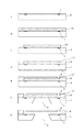
図4は本発明による構成を施した典型的なインクジェットプリントヘッド、図8は従来の構成を持つインクジェットプリントヘッド、図9は本発明の作用を更に詳細に説明するために、本発明の構成と似て非なる構成を持つ、具体的には各電気熱変換素子毎の個別のインク流路を形成するための隔離壁がインク供給口まで達している構成を持つインクジェットプリントヘッドである。これらのプリントヘッドは特開平4−10940号公開公報、特開平4−10941号公開公報に記載のインクジェット記録方法を特徴とするインク滴吐出手段、すなわち吐出時の発泡を外気と連通させる特徴を持つ。なお、各図とも電気熱変換素子を配した基板の正面から見た拡大図および、A−A’、B−B’方向の垂直断面図を示している。
【0012】
まずインクジェットプリントヘッド内に溶解せずに残った残留気泡がいかにして吐出に悪影響を与えるかを説明する。従来のインクジェットプリントヘッドでは、ある時点で供給口の直上付近において吐出口プレート内面に付着した残留気泡がそれを核として図8のように成長することが観察等によってわかっている。この残留気泡9は、インク滴の吐出によるインクジェットプリントヘッド内のインク流、具体的にはインク流路へインクを再充填するために生じる吐出口2に向かうインクの流れによって局所的にはインク流路に引き込まれやすい形状をしている。実際約150μm程度の残留気泡9が図8のような位置に存在していると、残留気泡9がインク流路内に引き込まれることによってインク流路内のインクが気泡によって分断され、インク流路へのインク供給不足が生じてしまう。本発明者らの観察によると、このまま更にインク滴吐出を継続していくと、徐々にこの残留気泡9が吐出口2側に向かっていき、この残留気泡9が外気と連通した瞬間にインクジェットプリントヘッド内のインクが空になってしまうという現象がおきることが判明した。
【0013】
この現象を図3に示す簡単なモデルを用いて説明する。図3において、今、細い管をインクで満たし、片方の端(A)を大気圧に、もう片方の端(B)を大気圧−P(kPa)に保つ。なお、管へのインクの出入りは自由であるとする。ここで、Pは具体的にはインクジェットプリントヘッドのインクタンクがインクを吸い上げている負圧力である。Aではインクの毛管力によって力の釣り合いがとられており、メニスカスが形成されている。ここで、インク中に径r(μm)の気泡9が存在するとし、インクの表面張力をγ(dyn/cm)とすれば、この気泡9の内圧は
大気圧−P+2γ/r (数1)
で表記できる。この状態で気泡9をA側に近づけ、ある時刻にこの気泡9を大気と連通させる。ここで
大気圧−P+2γ/r>大気圧 (数2)
の場合、すなわち
P<2γ/r (数3)
が成立している場合((i)参照)、気泡9内の内圧が大気圧より高いためにちょうど風船がしぼむように気泡9は大気に排出されて点線のようにメニスカスが形成される。逆に
大気圧−P+2γ/r<大気圧 (数4)
の場合、すなわち
P>2γ/r (数5)
が成立している場合((ii)参照)、気泡9内の内圧が大気圧より低いため、気泡9内に大気から急激な空気の流入が有り、管の中は一瞬にして点線のように空気でうまってしまう。
【0014】
上記の説明でわかるように、インク流路の近傍にP>2γ/rすなわち、
r>2γ/P
となるような大きさの残留気泡が存在する場合、この残留気泡が外気と連通した瞬間にインクジェットプリントヘッド内のインクが空になってしまうという現象が起こりうる。本発明者らの実験では、γ=47.8dyn/cmのインクを用い、タンク内負圧P=1kPaで確認を行っているが、それから計算される残留気泡の臨界径は95.6μmであり、ほぼ予測と実験結果が一致している。
【0015】
そこで本発明者らはこの残留気泡がインク供給特性に悪影響を与えるほど成長することを抑えるために吐出口プレート内面のインク供給口直上に突起を設ける構成を見出した。このように突起を設けることによって吐出口プレートの内面に付着し成長していく残留気泡に関してはこの残留気泡の径が突起の間隙以上には成長しないことが観察される。このため、仮にこの残留気泡が大気と連通したとしても突起の間隙が2γ/Pよりも短ければ、インクジェットプリントヘッド内のインクが空になってしまう最悪の事態は防ぐことができる。ただし、突起の間隙は狭ければ狭いほどよいというものではない。逆に狭すぎると本発明の効果を奏さないばかりか、吐出口プレートに付着した残留気泡が突起間に入り込み、インク吸引などの回復処理によっても除去できなくなってしまう。本発明者らの経験的見地によれば、突起間隙は最低でも10μm以上であることが望ましい。通常、主成分が水であるインクを吐出させるインクジェットプリントヘッドにおいて、インクはγ=40〜50dyn/cmであることが望ましいとされている。また、タンク内負圧がP=0.5〜2kPaで使用することが好ましいとされている。これらから、a=2γ/Pは通常40μm≦a≦200μmの範囲となることがわかる。したがって、突起の間隙を10μm以上40μm以下とすれば、通常インクジェットプリントヘッドに好適とされる各種のγを持つインク、各種のPを持つタンクにおいても好ましく作用する。
【0016】
更に検討を進めてみると、インク流路が基板のインク供給口からインク吐出エネルギー発生素子との間で隣接する吐出エネルギー発生素子が共有する共有部を有する構成とすることによりインク流路中に気泡が入り込むことを格段に低減できることがわかった。すなわち、図9に示されるように残留気泡が溜まると思われるインク供給口近傍から各電気熱変換素子までそれぞれ個別のインク流路で隔離された構成となっていると、インク流路のインク供給口側端が残留気泡で覆われることになり、インク流路内にこの残留気泡を取り込んでしまうことになる。本発明ではインク流路が基板のインク供給口からインク吐出エネルギー発生素子との間で隣接する吐出エネルギー発生素子が共有する共有部を有する構成としていることにより各電気熱変換素子毎の個別のインク流路へのインク供給は基板上で少なくとも2つ以上の経路を持つため、仮に一部のインク供給経路が残留気泡に覆われたとしても残りのインク供給経路からインクが供給されインク流路内に残留気泡が入り込む虞を格段に低減することが可能となる。
【0017】
図4は、本発明による構成すなわち、吐出口プレートのインク供給口に対応する位置に複数の突起を有するとともにインク流路が基板のインク供給口からインク吐出エネルギー発生素子との間で隣接する吐出エネルギー発生素子が共有する共有部を有する構成を施した典型的インクジェットプリントヘッドを示す模試図である。
【0018】
本発明による構成を施した典型的なインクジェットプリントヘッドでは、気泡の成長箇所が2個所存在することが確認されている。一つは吐出口プレートの内面に付着し成長していく残留気泡であり、もう一つは突起の先端部分に付着し成長していく残留気泡である。このうち前者の吐出口プレートの内面に付着し成長していく残留気泡については突起によって残留気泡の成長を抑制し、安定したインクの供給が行えるよう制御できることは前述のとうりである。一方、後者の突起の先端部分に付着し成長していく残留気泡に関しては、この残留気泡が図4のように成長することが観察等によってわかっている.この残留気泡もインク滴吐出後のインク流路へインクを再充填するために生じる、吐出口に向かうインクの流れによって局所的にわずかながら変形するが、従来例でおきたような悪い現象は見られなかった。これは吐出口プレート内面に設けた突起がちょうど残留気泡のインク流路内への進入を妨げるように構成されていること、およびインク流路が基板のインク供給口からインク吐出エネルギー発生素子との間で隣接する吐出エネルギー発生素子が共有する共有部を有するために図の矢印で示した広い範囲からインク供給を受けられることによってインク供給不足が生じにくいことが作用しているためである。すなわち、本発明を施した構成では、残留気泡がインク流路内に引き込まれることによってインク流路内のインクが分断されることはなく、インク流路へのインクの供給不足および大気との連通によるインクジェットプリントヘッド内のインクが空になってしまう現象が非常に生じにくくなっており、安定なインク滴の吐出と信頼性の高いインクジェットプリントヘッドを提供している。
【0019】
【実施例】
以下図面を参照しつつ本発明に係る実施例を詳細に説明する。
【0020】
(実施例1)
図1は本発明の基本的な形態を示すインクジェットプリントヘッドの摸式図であり、説明のために適当な面で切断してある。なお、本図およびこれ以下において、電気熱変換素子を駆動するための電気的な配線等は図示していない。図2は、各工程における図1のインクジェットプリント基板のA−A‘断面図である。図2では本発明のインクジェットプリントヘッドの製造方法を簡潔に示している。
【0021】
図1において4は吐出エネルギー発生素子1およびインク供給口3を備える基板であり、長溝状の貫通口からなるインク供給口3の長手方向の両側に吐出エネルギー発生素子である電気熱変換素子1がそれぞれ1列ずつ千鳥状に電気熱変換素子の間隔が片側列300dpiピッチで配列されている。この基板4上にはインク流路を形成するためのインク流路壁となる被覆樹脂層6が設けられており、この被覆樹脂層6上に更に吐出口2を備える吐出口プレート5が設けられている。ここで図1においては被覆樹脂層6と吐出口プレート5とは別部材として示されているが、この被覆樹脂層6をスピンコート等の手法によって基板4上に形成することにより被覆樹脂層6と吐出口プレート5とを同一部材として同時に形成することも可能である。7は吐出口プレート内面のインク供給口3直上に設けられる突起である。本発明では上述のようにこの突起7を設けることによりインクジェットプリントヘッド内部に残った気泡のインク液吐出に与える悪影響を緩和させることができるものである。更に本発明のインクジェットプリントヘッドはインク流路が基板のインク供給口からインク吐出エネルギー発生素子との間で隣接する吐出エネルギー発生素子が共有する共有部を有する構成となっている。具体的は各電気熱変換素子毎の個別のインク流路を形成するための隔離壁がインク供給口まで達していない構成となっている。ここで、この突起の形状としてはインク流路の流抵抗をできるだけ小さくする観点からインク供給口3から吐出口2に向かうインクの流れ方向に沿うリブによって形成されることが好ましいが、前述の間隙の範囲を満たすものであれば、例えば複数の柱からなるような形状であっても構わない。また、インク供給性の観点からは突起が基板から離間していることが望ましく、更にこの時の突起の離間距離は突起の端部から基板までの最短距離が前述の間隙同様10〜40μmの範囲に収まっていることが望ましい。また、突起7が上述のインクの流れ方向に沿うリブで形成されている場合にはこのリブを基板と接触させることにより吐出口プレートの強度を向上させることもできる。更にこの時リブの端部をテーパー形状とすることによってインク流路のインクの流抵抗を小さくすることも可能である。また、図1においては突起7の高さとインク流路壁6の高さが同じになっているが、突起7の高さは必ずしもインク流路壁の高さと同じにする必要はなく、この時も前述同様突起の端部から基板までの最短距離が前述の間隙同様10〜40μmの範囲に収まっているように形成されていればかまわない。
【0022】
また、前述の隔離壁に関しては、突起と同様にその端部から基板までの最短距離が10〜40μmの範囲となっていることが望ましい。
【0023】
以下に本発明に係るインクジェットプリントヘッドの製造方法の一例を示す。
【0024】
まず、Siチップ上にパターニング等によって複数の電気熱変換素子1およびそれらを駆動するための必要な配線(不図示)が施された基板4を用意し(図2−A)、該基板4上に、溶解可能な樹脂層12を形成する(図2−B)。前記樹脂層12において、フォトレジスト法などを用いてインク流路パターンを残すとともに、本発明の特徴であるノズル壁および供給口が形成される箇所の上方に適当な突起に相当する部分を除去する(図2−C)。更にこのようにインク流路パターンが形成された溶解可能な樹脂層12’上に、被覆樹脂層6を形成させ(図2−D)、前記被覆樹脂層6で吐出口2に相当する部分を除去する(図2−E)。次に基板4を背面より、基板を化学的にエッチングするなどして供給口3を形成する(図2−F)。より具体的には、強アルカリ溶液(KOH,NaOH,TMAH)を用いた異方性エッチングによって供給口3を形成する。最後に溶解可能な樹脂層12’を溶出させる(図2−G)ことにより、吐出口2、供給口3とそれらに連通する流路および供給口直上の吐出口プレート側面に形成された突起部7を備えたインクジェットプリントヘッドチップを得ることができる。このチップに電気熱変換素子を駆動するための配線基板と電気的接合等を行うことにより本発明のインクジェットプリントヘッドを得ることができる。
【0025】
上記のインクジェットプリントヘッドの製造方法は、特に特開平4−10940号公開公報、特開平4−10941号公開公報に記載のインクジェット記録方法をインク滴吐出手段とするインクジェットプリントヘッドの製造に好ましい。これらの各公報は、記録信号によって生じた電気熱変換素子上の気泡を外気と連通させることを特徴とするインク滴吐出方法であり、小インク滴(50pl以下)の吐出を可能にするインクジェットプリントヘッドを提供している。前記インクジェットプリントヘッドは、気泡を外気と連通させるため、吐出インク滴の体積は電気熱変換素子と吐出口との間にあるインクの体積にほとんど依存する。言い換えるとインクジェットプリントヘッドのノズル部分の構造によってほぼ決まるという特徴をもつ。したがって、前記インクジェットプリントヘッドは、ムラのない高品位な画像を出力することができる。本発明の構造は前記のインクジェットプリントヘッド、すなわち、気泡を外気と連通させるために、電気熱変換素子と吐出口間の(最短)距離が30μm以下であるようなインクジェットプリントヘッドに適用することで最大の効果を発揮するが、電気熱変換素子を配した基板面に垂直にインク滴を飛翔させるようなインクジェットプリントヘッドであれば、いずれも有効に作用させることができる。
【0026】
また、本発明のインクジェットプリントヘッドにおいては、隣接する電気熱変換素子を同時に駆動させないように分散駆動にて各電気熱変換素子を駆動させることによって、残留気泡による悪影響をさらに効果的に緩和できるものである。
【0027】
以下に本発明のインクジェットプリントヘッドの構造を具体的に説明する、尚各実施例についてはいずれも前述の図2−A〜Gに示す手順にしたがって作成したインクジェットプリントヘッドを使用し、ノズル間隔は片側列300dpiピッチ、吐出口プレートの肉厚8μm、本発明の特徴である突起およびノズル壁の高さは12μmである。評価に使用したインクは、キヤノン製染料系ブラックインク(表面張力47.8dyn/cm、粘度1.8cp、pH9.8)を使用した。
【0028】
(実施例1)
本実施例のインクジェットプリントヘッドを電気熱変換素子を配した基板の正面から見た拡大図と、A−A‘、B−B’断面図を図4に示す。
【0029】
本実施例の突起の吐出口プレート面への射影での寸法は20×150μmであり、各突起間の間隔は600dpiピッチ(42.3μm)で並んでいる。すなわち、隣接する突起の間隙は最低でも22.3μmある構成である。
【0030】
本実施例のインクジェットプリントヘッドを吐出周波数10kHzで駆動し、黒ベタを連続記録してその持続時間を計測し、比較評価を行った。結果は従来のインクジェットプリントヘッドに比較して本実施例では実に4倍近い程度も長い間黒ベタを印字することができた。
【0031】
(実施例2)
本実施例のインクジェットプリントヘッドを電気熱変換素子を配した基板の正面から見た拡大図と、A−A‘、B−B’断面図を図5に示す。
【0032】
本実施例の突起の吐出口プレート面への射影での寸法は40×40μmであり、各突起間は間隔80μm(間隙としては40μm)で並んでいる。
【0033】
本実施例のインクジェットプリントヘッドを吐出周波数10kHzで駆動し、黒ベタを連続記録してその持続時間を計測し、比較評価を行った。結果は従来のインクジェットプリントヘッドに比較して本実施例では実に4倍近い程度も長い間黒ベタを印字することができ、このような構成でも本発明は良好に作用する。
【0034】
さて、このような薄い膜状の吐出口プレートを有するインクジェットプリントヘッドでは、吐出口プレート自体の強度面での信頼性が低いことは明らかである。特に吐出口プレートが樹脂である場合には、吐出口プレートがインク等により膨潤し変形する虞がある。このようになると、インクジェットプリントヘッドのインク滴吐出特性自体に悪影響を及ぼしかねない。このため、本発明による突起を強度確保の対策としても提案したものが以下の実施例3、4である。突起を基板と吐出口プレートの両方に接触させることで、吐出口プレートに突起がないとき以上の強度を確保することが可能となり更に信頼性を上げることが可能となった。
【0035】
(実施例3)
本実施例のインクジェットプリントヘッドを電気熱変換素子を配した基板の正面から見た拡大図と、A−A‘、B−B’断面図を図6に示す。
【0036】
本実施例の突起の特徴は、突起が基板と吐出口プレートの両方に接することで吐出口プレートの強度を上げ、且つノズルへのインク供給を確保し、流抵抗を抑えるために突起の吐出口プレートに平行な面における幅が電気熱変換素子に向かって連続的に細くなっていることを特徴としている。本実施例の突起の吐出口プレート面への射影での幅は太いところで20μmであり、細いところで12μmとなっている。各突起間は間隔600dpi(42.3μm)で並んでいる。すなわち、突起と突起の間隙は最低でも22.3μmとなる構成である。
【0037】
本実施例のインクジェットプリントヘッドにおいても吐出周波数10kHzで駆動し、黒ベタを連続記録してその持続時間を計測し、比較評価を行った。結果は従来のインクジェットプリントヘッドに比較して本実施例では実に4倍近い程度も長い間黒ベタを印字することができ、このような構成でも本発明は良好に作用する。
【0038】
(実施例4)
本実施例のインクジェットプリントヘッドを電気熱変換素子を配した基板の正面から見た拡大図と、A−A‘、B−B’断面図を図7に示す。
【0039】
本実施例の突起の特徴は、同一の突起が供給口をまたいで基板と吐出口プレートの両方に接し実施例3よりも吐出口プレートの強度を向上させている。これは、さらにノズルへのインク供給を確保し、流抵抗を抑えるために突起の吐出口プレートに平行な面における幅が電気熱変換素子に向かって連続的に細くなっていることをも特徴としている。本実施例の突起の吐出口プレート面への射影での幅は太いところで20μmであり、細いところで12μmとなっている。各突起間は間隔600dpi(42.3μm)で並んでいる。すなわち、突起と突起の間隙は最低でも22.3μmとなる構成である。
【0040】
本実施例のインクジェットプリントヘッドにおいても吐出周波数10kHzで駆動し、黒ベタを連続記録してその持続時間を計測し、比較評価を行った。結果は従来のインクジェットプリントヘッドに比較して本実施例では実に3倍近い程度も長い間黒ベタを印字することができ、このような構成でも本発明は良好に作用する。
【0041】
【発明の効果】
以上、説明したように、本発明によれば、吐出口プレートの強度を上げつつ、インクジェットプリントヘッド内部に残った気泡のインク滴吐出に与える悪影響を緩和させ、ノズルへのインク供給を確保して安定なインク滴の吐出と信頼性の高いインクジェットプリントヘッドを提供することができる。
【図面の簡単な説明】
【図1】本発明の基本的な形態を示すインクジェットプリントヘッドの摸式図である。
【図2】本発明のインクジェットプリントヘッドの製造方法を説明するための説明図である。
【図3】インクジェットプリントヘッド内の残留気泡の様子を説明するための説明図である。
【図4】実施例1に係るインクジェットプリントヘッドを示す摸式図である。
【図5】実施例2に係るインクジェットプリントヘッドを示す摸式図である。
【図6】実施例3に係るインクジェットプリントヘッドを示す摸式図である。
【図7】実施例4に係るインクジェットプリントヘッドを示す摸式図である。
【図8】従来例のインクジェットプリントヘッドを示す摸式図である。
【図9】ノズル壁が供給口の直上にまで達しているインクジェットプリントヘッドの摸式図である。
【符号の説明】
1 吐出エネルギー発生素子
2 吐出口
3 供給口
4 基板
5 吐出口プレート
6 被覆樹脂層(ノズル壁)
7 突起
8 インク
9 残留気泡
10 ノズルに向かうインクの流れの向き
11 インクに流れによって生じる残留気泡の変形分
12 溶解可能な樹脂層
13 インク流路パターン[0001]
TECHNICAL FIELD OF THE INVENTION
The present invention relates to an ink jet print head that performs recording on a recording medium by flying ink droplets.
[0002]
[Prior art]
The ink jet recording method is one of so-called non-impact recording methods. As a feature of this recording method, the generation of noise during recording is so small that it can be ignored, high-speed recording and recording on various recording media are possible, and no special processing is required for so-called plain paper. And high-definition images can be obtained at low cost. Due to these advantages, not only printers as peripheral devices of computers but also printing systems such as copying machines, facsimile machines, word processors and the like have been rapidly spreading in recent years.
[0003]
Ink jet ink jetting methods widely used today include a method using an electrothermal transducer (heater) and a piezoelectric element (piezo) as a discharge energy generating element used to discharge ink droplets. There are methods, and in each case, it is possible to control the ejection of ink droplets by an electric signal. For example, the principle of an ink droplet discharging method using an electrothermal conversion element is that, by giving an electric signal to the electrothermal conversion element, the ink near the electrothermal conversion element is instantaneously boiled, and is caused by a phase change of the ink at that time. Ink droplets are ejected at high speed by rapid growth of bubbles. On the other hand, the principle of a method of ejecting ink droplets using a piezoelectric element is that an electric signal is applied to the piezoelectric element to displace the piezoelectric element, and the ink droplet is ejected by the pressure at the time of the displacement. Here, the former method does not require much space for the ejection energy generating element, has advantages such as a simple structure of the ink jet print head and easy integration of nozzles. On the other hand, the disadvantages inherent in this method include the volume fluctuation of flying ink droplets due to heat storage in the ink jet print head due to heat generated by the electrothermal transducer, the effect of cavitation due to defoaming on the electrothermal transducer, There is an effect on ink drop ejection characteristics and images due to bubbles remaining in the inkjet print head due to the dissolved air.
[0004]
Methods for solving these drawbacks are described in JP-A-54-161935, JP-A-61-185455, JP-A-61-249768, and JP-A-4-10941. Inkjet recording methods and inkjet printheads have been developed. That is, the ink jet recording method described in the above publication is characterized in that bubbles generated by driving the electrothermal transducer in accordance with a recording signal are communicated with the outside air. By using this recording method, it is possible to improve the volume stability of flying ink droplets, discharge small droplets at high speed, and improve the durability of heaters by eliminating cavitation generated when bubbles are eliminated. Can be easily obtained. In the above publication, as a configuration for communicating bubbles with outside air, there is a configuration in which the distance between the electrothermal conversion element and the discharge port is made much shorter than before. An inkjet print head having this configuration has an ejection port plate provided with ejection ports corresponding to the electrothermal transducers, and an ink supply port opened in the substrate to supply ink from the back of the substrate. It is configured such that the ink droplet flies almost perpendicularly to the substrate on which the electrothermal conversion elements are arranged. (See FIGS. 1 and 8). Here, it is desirable that the (shortest) distance between the electrothermal conversion element and the discharge port be 30 μm or less.
[0005]
[Problems to be solved by the invention]
Incidentally, the configuration described in the above-mentioned publication can sufficiently solve the one of the drawbacks mentioned above, that is, the effect of air dissolved in the ink on the ink droplet ejection characteristics and the image due to the residual air bubbles in the ink jet print head due to the air. However, it has been found that this problem is more likely to appear remarkably because the height of the flow path is low. In the following, the effect of air dissolved in the ink on ink drop ejection characteristics and images due to bubbles remaining in the inkjet print head will be described in detail. In the ink in the ink jet print head, air is usually dissolved in a saturated state. When the electrothermal transducer is driven in this state, when the foaming due to the phase change of the ink and the rapid adiabatic shrinkage of the bubbles are repeated, the air dissolved in the ink becomes undissolved bubbles having a diameter of about 1 μm or less. May appear suddenly in ink. It is known that such bubbles are redissolved in the ink for a time determined by the diameter of the bubble, the surface tension of the ink, the saturated vapor pressure of the air, and the like. For example, if the bubble diameter is 1 μm or less, the time required for dissolution is on the order of 1 μs or less. However, when a plurality of electrothermal transducers are continuously driven at a high frequency, such bubbles appear in the ink and coalesce and grow with each other before being re-dissolved. It is known that as the bubble diameter increases, the time required for re-dissolution increases significantly, but as a result, a plurality of residual bubbles of several tens μm to several hundreds of μm are stored in the inkjet print head. In such a case, these residual bubbles hardly redissolve in the ink, and adversely affect the ejection characteristics of the ink droplets. In other words, if the residual air bubbles block the ink flow path, the nozzles are not filled with sufficient ink, causing ejection failure. In addition, huge residual air bubbles (approximately several hundred μm) are generated inside the ink jet print head, and if the residual air bubbles happen to be communicated with the outside air, the outside air enters into the nozzle and the meniscus is destroyed. Therefore, the negative pressure for sucking up the ink in the ink tank may cause the ink inside the ink jet print head to be sucked up by the ink tank and cause all the nozzles to fail. The most effective solution for avoiding the adverse effects caused by such residual air bubbles is to discharge the residual air bubbles to the outside together with the ink by suction, pressurization, etc. from the ejection port before the residual air bubbles grow so badly that There is a method of performing a so-called suction (pressure) recovery process. However, in this case, the consumption of ink is significantly increased, and if this is performed during printing, the throughput naturally decreases. As another method, there is a method in which air dissolved in the ink is discharged from the ink by some method (degassing), and such ink is used for an ink jet print head. The time when this solution works most effectively is about several tens of minutes after deaeration of the ink, and since the apparatus for deaeration of the ink is relatively large, this method is used for a large-scale printing system. And so on.
[0006]
[Means for Solving the Problems]
The present invention has been made in view of the above-described problems, and alleviates the adverse effect of the bubbles remaining inside the ink jet print head on ink liquid discharge, thereby achieving stable ink droplet discharge and a highly reliable ink jet print head. It is intended to provide.
[0008]
In order to achieve the above object, an inkjet print head according to the present invention includes a plurality of ejection energy generating elements for generating energy used for ejecting ink droplets, and a plurality of ink ejection ports for ejecting the ink droplets. A substrate having an ink supply port consisting of a through hole extending along the direction in which the plurality of ejection energy generating elements are arranged in a row while disposing the plurality of ejection energy generating elements, and the plurality of ink ejection ports. An ejection port plate provided to face the ink supply port with respect to the substrate, and an ink formed between the substrate and the ejection port plate and communicating with the ink supply port and the ink ejection port. A flow path; and wherein the discharge port plate includes the ink flow path. Before A projection that contacts the substrate toward the substrate A projection provided toward the ink supply port side at a position facing the ink supply port, Having In addition, an isolation wall for forming an individual ink flow path for each of the adjacent ejection energy generating elements does not reach the ink supply port. It is characterized by the following.
[0009]
The ink jet print head of the present invention as described above has a discharge plate A projection provided toward the ink supply port side; A protrusion that contacts the substrate toward the substrate And that the separation wall for forming an individual ink flow path for each adjacent ejection energy generating element does not reach the ink supply port. This increases the strength of the ejection port plate, secures ink supply to the nozzles, and alleviates the adverse effect of bubbles remaining inside the ink jet print head on ink droplet ejection.
[0010]
BEST MODE FOR CARRYING OUT THE INVENTION
First, the operation of this configuration will be described in detail below with reference to the drawings and the like in comparison with a conventional example.
[0011]
FIG. 4 shows a typical ink jet print head having the structure according to the present invention, FIG. 8 shows an ink jet print head having a conventional structure, and FIG. 9 shows the structure of the present invention to explain the operation of the present invention in further detail. An ink jet print head having a similar configuration, specifically, a configuration in which an isolation wall for forming an individual ink flow path for each electrothermal conversion element reaches the ink supply port. These print heads have an ink droplet ejection means characterized by the ink jet recording method described in JP-A-4-10940 and JP-A-4-10941, that is, have a feature of communicating foaming at the time of ejection with outside air. . Each figure shows an enlarged view from the front of the substrate on which the electrothermal transducers are arranged, and a vertical cross-sectional view in the AA ′ and BB ′ directions.
[0012]
First, how the residual air bubbles remaining without dissolving in the inkjet print head adversely affect the ejection will be described. It has been found by observation and the like that in a conventional ink jet print head, residual bubbles attached to the inner surface of the discharge port plate near the supply port at some point grow as shown in FIG. The residual air bubbles 9 are locally generated by the ink flow in the ink jet print head due to the discharge of the ink droplets, specifically, the ink flow toward the
[0013]
This phenomenon will be described using a simple model shown in FIG. In FIG. 3, the thin tube is now filled with ink and one end (A) is kept at atmospheric pressure and the other end (B) is kept at atmospheric pressure-P (kPa). It is assumed that ink can freely enter and exit the tube. Here, P is a negative pressure at which the ink tank of the ink jet print head is sucking up the ink. In A, the forces are balanced by the capillary force of the ink, and a meniscus is formed. Here, it is assumed that
Atmospheric pressure-P + 2γ / r (Equation 1)
Can be represented by In this state, the
Atmospheric pressure-P + 2γ / r> Atmospheric pressure (Equation 2)
, That is,
P <2γ / r (Equation 3)
Is satisfied (see (i)), since the internal pressure in the
Atmospheric pressure−P + 2γ / r <Atmospheric pressure (Equation 4)
, That is,
P> 2γ / r (Equation 5)
Is satisfied (see (ii)), since the internal pressure in the
[0014]
As can be seen from the above description, P> 2γ / r near the ink flow path, ie,
r> 2γ / P
When a residual bubble having such a size as to exist exists, a phenomenon that the ink in the inkjet print head becomes empty at the moment when the residual bubble communicates with the outside air may occur. In the experiments of the present inventors, the confirmation was performed using an ink of γ = 47.8 dyn / cm and a negative pressure P in the tank of P = 1 kPa, and the critical diameter of the residual bubbles calculated therefrom was 95.6 μm. , Almost the same predictions and experimental results.
[0015]
Therefore, the present inventors have found a configuration in which a projection is provided immediately above the ink supply port on the inner surface of the ejection port plate in order to suppress the residual bubbles from growing so as to adversely affect the ink supply characteristics. It is observed that by providing the projections, the residual bubbles that grow by attaching to the inner surface of the discharge port plate do not grow beyond the gap between the projections. For this reason, even if the residual bubbles communicate with the atmosphere, the worst case in which the ink in the ink jet print head becomes empty can be prevented if the gap between the protrusions is shorter than 2γ / P. However, the smaller the gap between the projections, the better. Conversely, if it is too narrow, not only the effect of the present invention will not be achieved, but also residual air bubbles adhering to the ejection port plate will enter between the projections and cannot be removed even by a recovery process such as ink suction. According to the empirical viewpoint of the present inventors, it is desirable that the protrusion gap is at least 10 μm or more. Usually, in an ink jet print head that ejects an ink whose main component is water, it is considered that the ink preferably has a γ of 40 to 50 dyn / cm. Further, it is said that the tank is preferably used at a negative pressure in the tank of P = 0.5 to 2 kPa. From these, it can be seen that a = 2γ / P usually falls within the range of 40 μm ≦ a ≦ 200 μm. Therefore, if the gap between the projections is set to 10 μm or more and 40 μm or less, it works well for inks having various γ and various Ps which are generally suitable for an ink jet print head.
[0016]
Investigation is further conducted. The ink flow path has a common portion shared by the adjacent discharge energy generation elements between the ink supply port of the substrate and the ink discharge energy generation element, so that the ink flow path is formed in the ink flow path. It was found that air bubbles can be significantly reduced. In other words, as shown in FIG. 9, if the structure is separated from the vicinity of the ink supply port where the residual air bubbles are likely to accumulate to each of the electrothermal conversion elements by an individual ink flow path, the ink supply in the ink flow path The mouth end is covered with the residual air bubbles, and the residual air bubbles are taken into the ink flow path. In the present invention, since the ink flow path has a common portion shared by the adjacent ejection energy generating elements between the ink supply port of the substrate and the ink ejection energy generating element, individual ink for each electrothermal conversion element is provided. Since the ink supply to the flow path has at least two or more paths on the substrate, even if some of the ink supply paths are covered with residual bubbles, ink is supplied from the remaining ink supply paths and It is possible to remarkably reduce the possibility that residual air bubbles may enter the air.
[0017]
FIG. 4 shows a configuration according to the present invention, that is, a discharge port plate having a plurality of protrusions at positions corresponding to the ink supply ports and having an ink flow path adjacent to the ink discharge energy generating element from the ink supply port of the substrate. FIG. 3 is a schematic diagram illustrating a typical inkjet print head having a configuration having a sharing unit shared by energy generating elements.
[0018]
It has been confirmed that in a typical ink jet print head having the configuration according to the present invention, there are two places where bubbles grow. One is the residual air bubbles that adhere to and grow on the inner surface of the discharge port plate, and the other is the residual air bubbles that grow and adhere to the tip of the protrusion. As described above, it is possible to control the growth of the residual air bubbles that adhere to and grow on the inner surface of the discharge port plate by using the projections and control the ink to be supplied stably. On the other hand, with respect to the latter, the remaining bubbles that adhere to and grow at the tip of the projection, it is known from observations and the like that the remaining bubbles grow as shown in FIG. These residual bubbles are slightly deformed locally due to the flow of ink toward the discharge port, which is caused by refilling the ink flow path after the ink droplet is discharged. I couldn't. This is because the protrusion provided on the inner surface of the ejection port plate is configured to just prevent the residual air bubbles from entering into the ink flow path, and the ink flow path is connected to the ink ejection energy generating element from the ink supply port of the substrate. This is because there is a common portion shared between the adjacent ejection energy generating elements, so that it is possible to receive the ink supply from a wide range indicated by the arrow in the drawing, and thus it is possible to prevent the shortage of the ink supply from occurring. That is, in the configuration according to the present invention, the ink in the ink flow path is not divided by the residual air bubbles being drawn into the ink flow path, and the supply of the ink to the ink flow path is insufficient and the communication with the atmosphere is prevented. The phenomenon that the ink in the ink jet print head becomes empty due to the above is very unlikely to occur, and a stable ink droplet ejection and a highly reliable ink jet print head are provided.
[0019]
【Example】
Hereinafter, embodiments of the present invention will be described in detail with reference to the drawings.
[0020]
(Example 1)
FIG. 1 is a schematic view of an ink-jet printhead showing a basic mode of the present invention, which is cut at an appropriate plane for explanation. In addition, in this figure and below, the electric wiring etc. for driving an electrothermal transducer are not shown. FIG. 2 is a cross-sectional view of the inkjet printed circuit board of FIG. FIG. 2 briefly shows a method of manufacturing an ink jet print head according to the present invention.
[0021]
In FIG. 1, reference numeral 4 denotes a substrate provided with an ejection
[0022]
In addition, as for the above-mentioned isolation wall, it is desirable that the shortest distance from the end to the substrate is in the range of 10 to 40 μm as in the case of the projection.
[0023]
Hereinafter, an example of a method for manufacturing an ink jet print head according to the present invention will be described.
[0024]
First, a substrate 4 on which a plurality of
[0025]
The above-described method of manufacturing an ink jet print head is particularly preferable for manufacturing an ink jet print head using the ink jet recording method described in JP-A-4-10940 and JP-A-4-10941 as an ink droplet discharging means. Each of these publications is an ink droplet ejection method characterized in that bubbles on an electrothermal transducer generated by a recording signal are communicated with the outside air, and ink jet printing which enables ejection of small ink droplets (50 pl or less). Offering head. In the inkjet print head, the volume of the ejected ink droplet is almost dependent on the volume of the ink between the electrothermal conversion element and the ejection port because the bubble communicates with the outside air. In other words, it has a feature that it is almost determined by the structure of the nozzle portion of the ink jet print head. Therefore, the inkjet print head can output a high-quality image without unevenness. The structure of the present invention can be applied to the above-described ink jet print head, that is, an ink jet print head in which the (shortest) distance between the electrothermal transducer and the discharge port is 30 μm or less in order to allow air bubbles to communicate with the outside air. Although the maximum effect is exhibited, any ink jet print head that can fly ink droplets perpendicularly to the substrate surface on which the electrothermal conversion elements are arranged can be effectively used.
[0026]
Further, in the ink jet print head of the present invention, by driving each electrothermal conversion element by distributed driving so as not to drive adjacent electrothermal conversion elements at the same time, it is possible to more effectively mitigate the adverse effect due to residual bubbles. It is.
[0027]
Hereinafter, the structure of the ink jet print head of the present invention will be specifically described. In each example, the ink jet print head prepared according to the procedure shown in FIGS. The pitch of one side row is 300 dpi, the thickness of the discharge port plate is 8 μm, and the height of the projection and the nozzle wall, which is a feature of the present invention, is 12 μm. The ink used for the evaluation was a dye-based black ink manufactured by Canon (surface tension: 47.8 dyn / cm, viscosity: 1.8 cp, pH: 9.8).
[0028]
(Example 1)
FIG. 4 shows an enlarged view of the inkjet print head of the present embodiment as viewed from the front of the substrate on which the electrothermal transducers are arranged, and cross-sectional views taken along the lines AA ′ and BB ′.
[0029]
The dimensions of the projections of the present embodiment projected onto the discharge port plate surface are 20 × 150 μm, and the intervals between the projections are arranged at a pitch of 600 dpi (42.3 μm). That is, the gap between the adjacent protrusions is at least 22.3 μm.
[0030]
The inkjet print head of this example was driven at an ejection frequency of 10 kHz, black solids were continuously recorded, the duration was measured, and comparative evaluation was performed. As a result, in this embodiment, solid black could be printed for nearly four times as long as that of the conventional ink jet print head.
[0031]
(Example 2)
FIG. 5 shows an enlarged view of the inkjet print head of this embodiment as viewed from the front of the substrate on which the electrothermal conversion elements are arranged, and a cross-sectional view taken along AA ′ and BB ′.
[0032]
The dimensions of the projections of the present embodiment when projected onto the discharge port plate surface are 40 × 40 μm, and the intervals between the projections are 80 μm (the gap is 40 μm).
[0033]
The inkjet print head of this example was driven at an ejection frequency of 10 kHz, black solids were continuously recorded, the duration was measured, and comparative evaluation was performed. As a result, in this embodiment, solid black can be printed for almost four times as long as that of the conventional ink jet print head, and the present invention works well in such a configuration.
[0034]
By the way, it is clear that the reliability of the ejection port plate itself in terms of strength is low in the ink jet print head having such a thin film ejection port plate. In particular, when the ejection port plate is made of resin, the ejection port plate may be swelled and deformed by ink or the like. This can adversely affect the ink droplet ejection characteristics of the inkjet print head. For this reason, the following Examples 3 and 4 have also proposed the protrusion according to the present invention as a measure for securing the strength. By bringing the protrusion into contact with both the substrate and the discharge port plate, it is possible to secure a higher strength than when there is no protrusion on the discharge port plate, and it is possible to further increase the reliability.
[0035]
(Example 3)
FIG. 6 shows an enlarged view of the inkjet print head of this embodiment as viewed from the front of the substrate on which the electrothermal conversion elements are arranged, and a cross-sectional view taken along AA ′ and BB ′.
[0036]
The feature of the protrusion of this embodiment is that the protrusion comes into contact with both the substrate and the discharge port plate to increase the strength of the discharge port plate, to secure ink supply to the nozzles, and to suppress the flow resistance. The width in a plane parallel to the plate is continuously narrowed toward the electrothermal transducer. The width of the projection of the present embodiment projected onto the discharge port plate surface is 20 μm at a large position and 12 μm at a small position. The projections are arranged at an interval of 600 dpi (42.3 μm). That is, the gap between the projections is at least 22.3 μm.
[0037]
The ink jet print head of this example was also driven at an ejection frequency of 10 kHz, black solid was continuously recorded, the duration was measured, and comparative evaluation was performed. As a result, in this embodiment, solid black can be printed for almost four times as long as that of the conventional ink jet print head, and the present invention works well in such a configuration.
[0038]
(Example 4)
FIG. 7 shows an enlarged view of the inkjet print head of the present embodiment as viewed from the front of the substrate on which the electrothermal conversion elements are arranged, and cross-sectional views taken along the lines AA ′ and BB ′.
[0039]
The feature of the protrusion of the present embodiment is that the same protrusion straddles both the substrate and the discharge port plate across the supply port, and the strength of the discharge port plate is improved as compared with the third embodiment. This is also characterized by the fact that the width of the protrusion in the plane parallel to the discharge port plate is continuously narrowed toward the electrothermal transducer in order to secure the ink supply to the nozzles and suppress the flow resistance. I have. The width of the projection of the present embodiment projected onto the discharge port plate surface is 20 μm at a large position and 12 μm at a small position. The projections are arranged at an interval of 600 dpi (42.3 μm). That is, the gap between the projections is at least 22.3 μm.
[0040]
The ink jet print head of this example was also driven at an ejection frequency of 10 kHz, black solid was continuously recorded, the duration was measured, and comparative evaluation was performed. As a result, in the present embodiment, solid black can be printed for almost three times as long as that of the conventional ink jet print head, and the present invention works well in such a configuration.
[0041]
【The invention's effect】
As described above, according to the present invention, the strength of the ejection port plate is increased, the adverse effect on the ink droplet ejection of the bubbles remaining inside the ink jet print head is reduced, and the ink supply to the nozzles is secured. It is possible to provide a stable ink droplet ejection and a highly reliable ink jet print head.
[Brief description of the drawings]
FIG. 1 is a schematic view of an ink jet print head showing a basic embodiment of the present invention.
FIG. 2 is an explanatory diagram illustrating a method for manufacturing an ink jet print head of the present invention.
FIG. 3 is an explanatory diagram for explaining a state of a residual bubble in an inkjet print head.
FIG. 4 is a schematic diagram illustrating an inkjet print head according to the first embodiment.
FIG. 5 is a schematic view illustrating an inkjet print head according to a second embodiment.
FIG. 6 is a schematic diagram illustrating an inkjet print head according to a third embodiment.
FIG. 7 is a schematic diagram illustrating an inkjet print head according to a fourth embodiment.
FIG. 8 is a schematic diagram showing a conventional ink jet print head.
FIG. 9 is a schematic view of an ink jet print head in which a nozzle wall reaches just above a supply port.
[Explanation of symbols]
1 Discharge energy generating element
2 Discharge port
3 Supply port
4 Substrate
5 Discharge port plate
6 coating resin layer (nozzle wall)
7 Projection
8 ink
9 residual air bubbles
10 Direction of ink flow toward nozzle
11 Residual air bubble deformation caused by ink flow
12 Soluble resin layer
13 Ink channel pattern
Claims (4)
前記インク滴を吐出する複数のインク吐出口と、
前記複数の吐出エネルギー発生素子を列状に配するとともに前記吐出エネルギー発生素子の配列方向に沿って延在する貫通口からなるインク供給口を有する基板と、
前記複数のインク吐出口を備え、前記基板に対して前記インク供給口と対向するように設けられた吐出口プレートと、
前記基板と前記吐出口プレートとの間に形成され、前記インク供給口と前記インク吐出口とを連通するインク流路と、
を備え、
前記吐出口プレートは、前記インク流路に前記基板へ向かって当該基板に接触する突起と、前記インク供給口と対向する位置に当該インク供給口側へ向かって設けられた突起と、を有するとともに、隣接する前記吐出エネルギー発生素子毎の個別のインク流路を形成するための隔離壁が前記インク供給口まで達していないことを特徴とするインクジェットプリントヘッド。A plurality of ejection energy generating elements that generate energy used to eject ink droplets,
A plurality of ink ejection ports for ejecting the ink droplets,
A substrate having an ink supply port formed of a through-hole extending along the direction in which the plurality of ejection energy generating elements are arranged in a row and arranging the plurality of ejection energy generating elements;
An ejection port plate comprising the plurality of ink ejection ports, provided to face the ink supply port with respect to the substrate,
An ink flow path formed between the substrate and the discharge port plate and communicating the ink supply port and the ink discharge port;
With
The discharge port plate has a projection in contact with the substrate toward the front Stories substrate to the ink flow path, and a projection provided towards the ink supply port side at a position opposite to the ink supply port An ink jet print head, wherein an isolation wall for forming an individual ink flow path for each of the adjacent ejection energy generating elements does not reach the ink supply port .
Priority Applications (9)
| Application Number | Priority Date | Filing Date | Title |
|---|---|---|---|
| JP30471996A JP3581504B2 (en) | 1996-11-15 | 1996-11-15 | Inkjet print head |
| US08/969,837 US6137510A (en) | 1996-11-15 | 1997-11-13 | Ink jet head |
| AU45177/97A AU4517797A (en) | 1996-11-15 | 1997-11-14 | Ink jet head |
| DE69727533T DE69727533T2 (en) | 1996-11-15 | 1997-11-14 | ink-jet head |
| CN97122680A CN1079739C (en) | 1996-11-15 | 1997-11-14 | Ink-jetting head |
| CA002221119A CA2221119C (en) | 1996-11-15 | 1997-11-14 | Ink jet head |
| EP97120009A EP0842776B1 (en) | 1996-11-15 | 1997-11-14 | Ink-jet head |
| ES97120009T ES2212032T3 (en) | 1996-11-15 | 1997-11-14 | HEAD FOR INK JETS. |
| KR1019970060266A KR100269927B1 (en) | 1996-11-15 | 1997-11-15 | Ink jet head |
Applications Claiming Priority (1)
| Application Number | Priority Date | Filing Date | Title |
|---|---|---|---|
| JP30471996A JP3581504B2 (en) | 1996-11-15 | 1996-11-15 | Inkjet print head |
Publications (2)
| Publication Number | Publication Date |
|---|---|
| JPH10146976A JPH10146976A (en) | 1998-06-02 |
| JP3581504B2 true JP3581504B2 (en) | 2004-10-27 |
Family
ID=17936399
Family Applications (1)
| Application Number | Title | Priority Date | Filing Date |
|---|---|---|---|
| JP30471996A Expired - Fee Related JP3581504B2 (en) | 1996-11-15 | 1996-11-15 | Inkjet print head |
Country Status (1)
| Country | Link |
|---|---|
| JP (1) | JP3581504B2 (en) |
Families Citing this family (7)
| Publication number | Priority date | Publication date | Assignee | Title |
|---|---|---|---|---|
| US7370944B2 (en) * | 2004-08-30 | 2008-05-13 | Eastman Kodak Company | Liquid ejector having internal filters |
| JP4701682B2 (en) * | 2004-11-08 | 2011-06-15 | ブラザー工業株式会社 | Inkjet printer head |
| JP4854328B2 (en) * | 2005-04-13 | 2012-01-18 | キヤノン株式会社 | Liquid discharge recording head |
| JP2007283501A (en) | 2006-04-12 | 2007-11-01 | Canon Inc | Inkjet recording head |
| JP5388615B2 (en) | 2009-02-06 | 2014-01-15 | キヤノン株式会社 | Inkjet recording head |
| JP5302378B2 (en) | 2011-01-14 | 2013-10-02 | パナソニック株式会社 | Inkjet head |
| JP7026437B2 (en) * | 2016-12-16 | 2022-02-28 | エスアイアイ・プリンテック株式会社 | Liquid injection head and liquid injection recording device |
-
1996
- 1996-11-15 JP JP30471996A patent/JP3581504B2/en not_active Expired - Fee Related
Also Published As
| Publication number | Publication date |
|---|---|
| JPH10146976A (en) | 1998-06-02 |
Similar Documents
| Publication | Publication Date | Title |
|---|---|---|
| US6137510A (en) | Ink jet head | |
| JP3675272B2 (en) | Liquid discharge head and method for manufacturing the same | |
| JP3957851B2 (en) | Liquid ejection method | |
| JPH0452220B2 (en) | ||
| US7887159B2 (en) | Liquid ejecting head and ink jet printing apparatus | |
| US6305080B1 (en) | Method of manufacture of ink jet recording head with an elastic member in the liquid chamber portion of the substrate | |
| KR20010040355A (en) | Apparatus and method for using bubble as virtual valve in microinjector to eject fluid | |
| US6805432B1 (en) | Fluid ejecting device with fluid feed slot | |
| JPH1199649A (en) | Ink jet head, manufacture thereof, and ink jet unit | |
| JP2004001488A (en) | Inkjet head | |
| US6609784B2 (en) | Ink jet recording device and a method for designing the same | |
| JP3581504B2 (en) | Inkjet print head | |
| US6854820B2 (en) | Method for ejecting liquid, liquid ejection head and image-forming apparatus using the same | |
| JP2019514731A (en) | Fluid ejection device with dividing wall | |
| US6508946B1 (en) | Method for manufacturing ink jet recording head, ink jet recording head, and ink jet recording apparatus | |
| JP4018272B2 (en) | Ink jet print head and ink jet printing device equipped with the head | |
| CN101804728A (en) | Ink jet printing head | |
| JP3559698B2 (en) | INK JET PRINT HEAD, INK JET PRINTING DEVICE, AND THEIR MANUFACTURING METHOD | |
| JPH10181021A (en) | Ink jet head, ink jet printing device, and ink jet printing method | |
| JP3684046B2 (en) | Ink jet recording head and ink jet recording apparatus | |
| JP2708519B2 (en) | Inkjet recording head | |
| JP2001171117A (en) | Ink jet recording head | |
| JP3563999B2 (en) | Liquid discharge method, liquid discharge head and liquid discharge device | |
| AU780024B2 (en) | Ink jet head | |
| JP2001150679A (en) | Ink-jet printing head |
Legal Events
| Date | Code | Title | Description |
|---|---|---|---|
| A521 | Written amendment |
Free format text: JAPANESE INTERMEDIATE CODE: A523 Effective date: 20031222 |
|
| A02 | Decision of refusal |
Free format text: JAPANESE INTERMEDIATE CODE: A02 Effective date: 20040127 |
|
| A521 | Written amendment |
Free format text: JAPANESE INTERMEDIATE CODE: A523 Effective date: 20040329 |
|
| A521 | Written amendment |
Free format text: JAPANESE INTERMEDIATE CODE: A523 Effective date: 20040525 |
|
| A911 | Transfer of reconsideration by examiner before appeal (zenchi) |
Free format text: JAPANESE INTERMEDIATE CODE: A911 Effective date: 20040602 |
|
| TRDD | Decision of grant or rejection written | ||
| A01 | Written decision to grant a patent or to grant a registration (utility model) |
Free format text: JAPANESE INTERMEDIATE CODE: A01 Effective date: 20040713 |
|
| A61 | First payment of annual fees (during grant procedure) |
Free format text: JAPANESE INTERMEDIATE CODE: A61 Effective date: 20040723 |
|
| R150 | Certificate of patent (=grant) or registration of utility model |
Free format text: JAPANESE INTERMEDIATE CODE: R150 |
|
| FPAY | Renewal fee payment (prs date is renewal date of database) |
Free format text: PAYMENT UNTIL: 20080730 Year of fee payment: 4 |
|
| FPAY | Renewal fee payment (prs date is renewal date of database) |
Free format text: PAYMENT UNTIL: 20080730 Year of fee payment: 4 |
|
| FPAY | Renewal fee payment (prs date is renewal date of database) |
Free format text: PAYMENT UNTIL: 20090730 Year of fee payment: 5 |
|
| FPAY | Renewal fee payment (prs date is renewal date of database) |
Free format text: PAYMENT UNTIL: 20090730 Year of fee payment: 5 |
|
| FPAY | Renewal fee payment (prs date is renewal date of database) |
Free format text: PAYMENT UNTIL: 20100730 Year of fee payment: 6 |
|
| FPAY | Renewal fee payment (prs date is renewal date of database) |
Free format text: PAYMENT UNTIL: 20100730 Year of fee payment: 6 |
|
| FPAY | Renewal fee payment (prs date is renewal date of database) |
Free format text: PAYMENT UNTIL: 20110730 Year of fee payment: 7 |
|
| FPAY | Renewal fee payment (prs date is renewal date of database) |
Free format text: PAYMENT UNTIL: 20120730 Year of fee payment: 8 |
|
| FPAY | Renewal fee payment (prs date is renewal date of database) |
Free format text: PAYMENT UNTIL: 20120730 Year of fee payment: 8 |
|
| FPAY | Renewal fee payment (prs date is renewal date of database) |
Free format text: PAYMENT UNTIL: 20130730 Year of fee payment: 9 |
|
| LAPS | Cancellation because of no payment of annual fees |