CN101804728A - Ink jet printing head - Google Patents
Ink jet printing head Download PDFInfo
- Publication number
- CN101804728A CN101804728A CN201010171105A CN201010171105A CN101804728A CN 101804728 A CN101804728 A CN 101804728A CN 201010171105 A CN201010171105 A CN 201010171105A CN 201010171105 A CN201010171105 A CN 201010171105A CN 101804728 A CN101804728 A CN 101804728A
- Authority
- CN
- China
- Prior art keywords
- ink
- printhead
- ejection
- ejection port
- ejiction opening
- Prior art date
- Legal status (The legal status is an assumption and is not a legal conclusion. Google has not performed a legal analysis and makes no representation as to the accuracy of the status listed.)
- Pending
Links
Images


Classifications
-
- B—PERFORMING OPERATIONS; TRANSPORTING
- B41—PRINTING; LINING MACHINES; TYPEWRITERS; STAMPS
- B41J—TYPEWRITERS; SELECTIVE PRINTING MECHANISMS, i.e. MECHANISMS PRINTING OTHERWISE THAN FROM A FORME; CORRECTION OF TYPOGRAPHICAL ERRORS
- B41J2/00—Typewriters or selective printing mechanisms characterised by the printing or marking process for which they are designed
- B41J2/005—Typewriters or selective printing mechanisms characterised by the printing or marking process for which they are designed characterised by bringing liquid or particles selectively into contact with a printing material
- B41J2/01—Ink jet
- B41J2/135—Nozzles
- B41J2/14—Structure thereof only for on-demand ink jet heads
- B41J2/14016—Structure of bubble jet print heads
- B41J2/14032—Structure of the pressure chamber
- B41J2/14048—Movable member in the chamber
-
- B—PERFORMING OPERATIONS; TRANSPORTING
- B41—PRINTING; LINING MACHINES; TYPEWRITERS; STAMPS
- B41J—TYPEWRITERS; SELECTIVE PRINTING MECHANISMS, i.e. MECHANISMS PRINTING OTHERWISE THAN FROM A FORME; CORRECTION OF TYPOGRAPHICAL ERRORS
- B41J2/00—Typewriters or selective printing mechanisms characterised by the printing or marking process for which they are designed
- B41J2/005—Typewriters or selective printing mechanisms characterised by the printing or marking process for which they are designed characterised by bringing liquid or particles selectively into contact with a printing material
- B41J2/01—Ink jet
- B41J2/135—Nozzles
- B41J2/14—Structure thereof only for on-demand ink jet heads
- B41J2/1433—Structure of nozzle plates
Abstract
The present invention provides a printing head, an ink jet printing apparatus, and an ink jet printing method capable of achieving high-speed printing while realizing high-quality image. An ejection port face where an ejection port of the printing head is located is formed so that the normal line thereof intersects with an axis line of a nozzle at a predetermined angle. The ejection port face inclines in a relative moving direction of the printing head with a printing medium as a reference.
Description
The application is to be on April 19th, 2007 applying date, and application number is dividing an application of 200710096617.8 Chinese patent application.
Technical field
The present invention relates to a kind of ink jet-print head that can utilize heat energy to come ink-jet.
Background technology
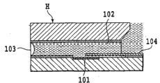
In inkjet-printing device, employing can utilize electrothermal transducer (heater) or piezoelectric element to spray for example printhead of ink of liquid.Shown in Fig. 9 A, in the printhead H that adopts electrothermal transducer 101, the liquid in the stream 102 bubbles (referring to Fig. 9 B and 9C) via the heat of this electrothermal transducer 101, and utilizes the foaming energy of the bubble B that generates this moment, from ejiction opening 103 ejection liquid.Then, bubble B froth breaking shown in Fig. 9 D and 9E.For this routine printhead H, movable valve 104 is located in the stream 102 so that the foaming of bubble B can act on the direction of ejiction opening 103 effectively.Adopt the inkjet-printing device of this printhead H to come print image attached to print media by making from the liquid of ejiction opening 103 ejections.In this printing equipment, the demand of print speed high speed grows with each passing day.
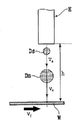
For this printhead H, along with print speed is accelerated, a new problem is more and more obvious.Shown in Fig. 9 D, the fluid column that is pushed away ejiction opening 103 when disjunction also forms with this main droplet Dm and to be called appendicular secondary drop Ds when forming drop (main droplet), shown in Fig. 9 E.When these main droplets Dm and secondary drop Ds depart from the ground land on print media the time mutually, the printing image quality in images can descend.Shown in Figure 10 A, the ejection that the ejection of secondary drop Ds regularly is later than main droplet Dm regularly, and spouting velocity Vs that should pair drop Ds is less than the spouting velocity Vm of main droplet Dm.Therefore, when the relative moving speed of printhead H and print media W accelerated, the deviation d of the landing positions of the landing positions of main droplet Dm and secondary drop Ds became big (referring to Figure 10 B and 10C).Figure 10 A, 10B and 10C represent that print media W moves with respect to printhead H.D1 utilizes main droplet Dm to be formed on point on the print media W, and D2 utilizes secondary drop Ds to be formed on point on the print media W.
Usually,, can dwindle the ejection port face (the residing face of ejiction opening) of printhead and the distance h (referring to Figure 10 A) between the print media, perhaps increase the spouting velocity of liquid for the deviation of the landing positions that makes main droplet and secondary drop is little.
Simultaneously, the Japan Patent spy opens No.2000-263788 and has described a kind of main droplet of ink and consistent structure of emission direction of secondary drop of making.When the spray nozzle part that contains ejiction opening and stream is formed by multiple material, produce the difference of storeroom surface energy, in other words, to the difference of ink wetability.It is owing to this difference to the ink wetability takes place by this true proposition of deviation at the emission direction of main droplet and appendicular emission direction that the Japan Patent spy opens the structure of describing among the No.2000-263788.That is to say that ejection port face tilts so that the circuit portion on the low-surface-energy material side of living in is shorter than the circuit portion on the high surface energy material side of living in.This makes main droplet consistent with appendicular emission direction.
Yet so that the deviation of the landing positions of main droplet and secondary drop hour, it is limited shortening this distance h when the ejection port face of attempting to shorten printhead and the distance h between the print media (referring to Figure 10 A).When distance h too in short-term, liquid provides print media thereon to contact the ejection port face of printhead owing to wrinkle.In addition, owing to the liquid that rebounds from surface of print media or attached to the fog-like liquid on the ejection port face, it is bad the liquid ejection also can to occur.So that the deviation of the landing positions of main droplet and secondary drop hour, it equally also is limited quickening when attempting the accelerating liquid spouting velocity.
Therefore, only ejection port face by shortening printhead and the distance h between the print media or by the accelerating liquid spouting velocity are difficult to make when realizing higher print speed the deviation of landing positions of main droplet and secondary drop little.
On the other hand, the Japan Patent spy opens No.2000-263788 and only discloses a kind of consistent structure of emission direction that is used to make main droplet shown in Figure 10 A and secondary drop.Adopt this structure, can not solve with print speed shown in Figure 10 B and the 10C and accelerate relevant problem, that is, can not suppress the deviation of the landing positions of main droplet and secondary drop.
Usually as mentioned above, can not suppress fully along with print speed is accelerated and the deviation of the landing positions of the main droplet that increases and secondary drop.Especially, be difficult to defer to the desirable requirement of industrial inkjet-printing device, that is, print speed faster and the printing image the higher requirement of quality.In industrial inkjet-printing device, for example, when the type slug font code, the deviation of the landing positions of main droplet and secondary drop will be fatal.Bar code is the printing information that constitutes by different secret note of thickness and white space.Therefore, when the deviation of the landing positions of main droplet and secondary drop increased, readable specification was shifted out in the size in bar or space or position, and this can not read bar code.
Figure 11,12A and 12B are the key diagrams of print result under the situation that the landing positions of main droplet and secondary drop departs from so-called serial scan formula inkjet-printing device and wide line inkjet-printing device.
In so-called serial scan formula inkjet-printing device, as shown in figure 11, by repeating when the main scanning direction shown in the arrow X moves, to spray the operation of liquid and the operation that transmits print media W along the sub scanning direction shown in the arrow Y, print image on this print media W in turn at printhead H.Method of printing among Figure 11 be a kind of printhead H along shown in the arrow X1 toward direction with along the bi-directional printing method of returning direction print image when moving shown in the arrow X2.In scanning, some D2 forms the center towards direct of travel (X1 direction) the deviation point D1 of printhead H at the former.On the other hand, in latter's flyback retrace, some D2 forms the center towards direct of travel (X2 direction) the deviation point D1 of printhead H.When the sweep speed (along the translational speed of arrow X1 and X2 direction) of printhead H was hanged down, some D2 was formed in the D1 as shown in figure 11.Yet when sweep speed accelerated, some D2 was formed on outside the D1.As a result, when the flying print bar code, this bar code can not be read.
In so-called wide line inkjet-printing device, shown in Figure 12 A, by transmit continuously along arrow Y1 direction print media W and printhead H fixing in from this printhead H ejection liquid, print image continuously on this print media W.Point D2 forms the center of departing from D1 towards the direction (arrow Y2 direction) opposite with the direction of transfer (arrow Y1) of print media W.Arrow Y2 direction is the relatively move direction of printhead H with respect to print media W.When the transfer rate of print media W was hanged down, some D2 was formed in the D1 shown in Figure 12 A.Yet when the transfer rate of print media W was high, some D2 was formed on outside the D1 shown in Figure 12 B.As a result, when the flying print bar code, this bar code can not be read.
Summary of the invention
The invention provides can be when realizing flying print printhead, inkjet-printing device and the inkjet printing methods of print high quality images.
In a first aspect of the present invention, a kind of ink jet-print head that can utilize heat energy to come ink-jet is provided, comprising: thus provide a plurality of electrothermal transducers to produce the heating plate of bubble with heating ink; Top board, described top board and described heating plate are staggered relatively to form and the corresponding a plurality of flow path of ink of described a plurality of electrothermal transducers; Ejection port face is formed with and the corresponding a plurality of ejiction openings of described a plurality of flow path of ink at this ejection port face place, and described ejection port face has at a predetermined angle the normal with the axes intersect of described flow path of ink; And nozzle wall, described nozzle wall is placed on the described heating plate and in the zone between described a plurality of electrothermal transducers and described a plurality of ejiction opening, wherein, the inner wall element of described nozzle wall and described top board is made by identical resin material, and described inner wall element forms flow path of ink with described nozzle wall; And wherein, the growth and the contraction of the bubble that forms along with utilizing described electrothermal transducer to heat, ink is from described ejiction opening ejection and be divided into main droplet and secondary drop.
In a second aspect of the present invention, a kind of inkjet-printing device is provided, comprising: mobile device, printhead and print media relatively move; And control device, in relatively move printhead and print media, from the ejiction opening ejection liquid of this printhead.
In a third aspect of the present invention, a kind of inkjet printing methods is provided, by adopting the printhead that can spray liquid in relatively move printhead and print media, to spray liquid print image on print media from this ejiction opening from the ejiction opening of nozzle tip, wherein, the ejection port face of the residing printhead of ejiction opening form make this ejection port face normal at a predetermined angle with the axes intersect of nozzle, and wherein when print image on print media, printhead and print media relatively move, so that ejection port face tilts towards the direction that relatively moves that with the print media is the printhead of benchmark.
According to the present invention, the normal of the ejection port face of the residing printhead of ejiction opening forms at a predetermined angle the axes intersect with nozzle, and ejection port face tilts towards the direction relevant with the direction that relatively moves of printhead and print media.This allows to break up on one's own initiative from the main droplet of the liquid of ejiction opening ejection and the emission direction of secondary drop.Main droplet is to form by the liquid near the nozzle the ejection ejiction opening, and secondary drop is to form away from the liquid in the nozzle of ejiction opening by ejection.As described, the emission direction that initiatively breaks up main droplet and secondary drop makes the deviation of this main droplet and the landing positions of secondary drop on print media little, and when realizing high speed printing, print high quality images.
From following (with reference to the accompanying drawing) explanation to example embodiment, further feature of the present invention will become apparent.
Description of drawings
Fig. 1 is the partial cut-away perspective view according to the major part of the printhead of first embodiment of the invention;
Among Fig. 2 A, 2B, 2C, 2D and the 2E each is the key diagram of the liquid ejection process of printhead shown in Figure 1;
Fig. 3 is the key diagram at inclination angle of the ejiction opening of printhead shown in Figure 1;
Fig. 4 is the key diagram of the liquid emission direction of printhead shown in Figure 1;
Among Fig. 5 A, 5B and the 5C each is the key diagram from the landing positions of the drop of printhead ejection shown in Figure 1;
Fig. 6 is the decomposition diagram of printhead shown in Figure 1;
Fig. 7 is the schematic front view with inkjet-printing device of printhead shown in Figure 1;
Among Fig. 8 A, 8B, 8C, 8D and the 8E each is the key diagram according to the liquid ejection process of the printhead of second embodiment of the invention;
Among Fig. 9 A, 9B, 9C, 9D and the 9E each is the key diagram of the liquid ejection process of existing printhead;
Among Figure 10 A, 10B and the 10C each is the key diagram from the landing positions of the drop of the ejection of printhead shown in Fig. 9 A;
Figure 11 is the key diagram that utilizes the printing example of the serial scan formula inkjet-printing device printing of adopting printhead shown in Fig. 9 A; And
Among Figure 12 A and the 12B each is to utilize the key diagram of the printing example of the wide line inkjet-printing device printing of adopting printhead shown in Fig. 9 A.
The specific embodiment
Now will be based on description of drawings the present invention.
(first embodiment)
Fig. 6 is the decomposition diagram according to the printhead of first embodiment of the invention.The printhead of present embodiment is used as the printhead 110 of ejection liquid ink in inkjet-printing device.The ejection element of electrothermal transducer as described below (bubble generation equipment), public liquid chamber, stream, ejiction opening etc. is disposed in Reference numeral 111 indications, and the ceramic wafer of electrical wire board as described below is disposed in 112 indications.Public liquid chamber in the ejection element 111 many streams interior with being located at stream formation part are communicated with.The China ink jar that ink is never represented is supplied to stream to form the ink supply port of part.A plurality of nozzles form with stream, ejiction opening, electrothermal transducer (bubble generation equipment) etc. and form a line.Introduce of the ejiction opening ejection of the ink of public liquid chamber from each nozzle from ink supply port.
Fig. 7 is the front schematic view that can adopt the wide line inkjet-printing device 120 of printhead 110 print images.Printing equipment 120 provides along the direction of transfer shown in the arrow Y1 and transmits print media the W for example transport unit 121 of paper and the feed portion 122 that print media W is supplied to this transport unit 121.Six printheads 110 are removably mounted on the printing equipment 120 of present embodiment.Give these printheads 110 from the yellow (Y) of corresponding print cartridge 123, shallow magenta (LM), magenta (M), light cyan (LC), cyan (C) and black (K) ink feed.Six printheads 110 are configured to depart from along the direction of transfer of print media W.The direction that the nozzle rows of each printhead 110 is intersected towards the direction of transfer with print media W (present embodiment is a vertical direction) is extended.
Reference numeral 124 indications are used to recover to handle to keep the ink ejection recovery unit in good condition of printhead 110.Recover to handle and for example to comprise from ejiction opening suction ejection or pressurization ejection and be not used in the processing of the ink that image prints and the processing that is not used in the ink that image prints from ejiction opening ejection (pre-ejection).Recover to handle the processing of the ejection port face (the residing face of ejiction opening) that also comprises wiping printhead 110.Reference numeral 125 indications are used to operate the operating surface board of printing equipment 120.
Fig. 1 is near the partial cut-away perspective view of the part of the nozzle of printhead 110.
A plurality ofly be used for heating ink and make the heater (electrothermal transducer) 2 that this ink bubbles be located at heater plates 1.For example tantalum nitride is as heater 2 for resistor, and its thickness for example 0.01 to 0.5 μ m and its thin-film electro resistance is per unit square 10 to 300 Ω.The aluminium electrode (not shown) that is used for electrical conduction is connected with heater 2.On the one side of electrode, connect the switching transistor (not shown) be used to control with the electrical conduction of heater 2.The IC that the switching transistor utilization is made of with door equipment circuit etc. control drives and controls, and according to the signal controlling heater 2 of printing equipment.
Every of being formed in many streams 3 locates heater 2.One end of every stream 3 is communicated with corresponding ejiction opening 4, and the other end of every stream 3 is communicated with public liquid chamber 5.Stream 3 is surrounded by the top board nozzle 8 of the nozzle dike 7 of heater plate 1, nozzle wall 6, the about 5-10 μ of thickness m and the about 2 μ m of thickness and forms tubulose.In the present embodiment, nozzle wall 6, nozzle dike 7 and top board nozzle 8 are formed by photoimageable epoxy.
Ejiction opening 4 residing ejection port face F have following pre-determined tilt angle θ.
As shown in Figure 3, ejection port face F is not orthogonal to axis (axis of the nozzle) L1 of stream 3, but the normal L2 of this ejection port face F is with respect to axis L1 tilt angle theta.In other words, ejection port face F form make normal L2 and nozzle axis L1 at a predetermined angle θ intersect.Ejection port face F is tilted and is the rightabout (arrow Y2 direction) towards the direction of transfer Y1 of print media W, i.e. the direction that relatively moves of printhead 110 when being benchmark with print media W.Therefore, ejection port face F is by the face F0 perpendicular to axis L1 is formed towards the direction that relatively moves (the arrow Y2 direction) tilt angle theta of printhead 110.As described below, consider the relative moving speed of print media W and printhead 10 etc., the size of set angle θ.
Fig. 2 A to 2E is the key diagram from the ejection process of ejiction opening 4 ejection ink droplets.
Fig. 2 A is illustrated in the preceding state of ink in the heating channel 3, that is, and and the state that heater 2 is not switched on.Near the ejiction opening 4 ink forms meniscus M.
Fig. 2 B and 2C represent to work as heater 2 energisings and adstante febre is accompanied by this ink film boiling and the state of generation bubble B in the ink that is heated.In the case, utilizing with valve seat 11 sides is supporting-point and mobile movable valve 9, and the ink emission direction is guided in the direction of propagation based on the pressure of the generation of bubble B.The pressure that ink in the stream 3 generates via bubble is from ejiction opening 4 ejections, and is accompanied by this bubble B growth and forms the fluid column that fluid column is for example represented among Fig. 2 C.
Fig. 2 D and 2E are illustrated in the state that stops being in after utilizing heater 2 heating inks the bubble B of contraction process.Near the ejiction opening 4 ink is drawn into stream 3 according to the contraction of bubble B.Because inertia force acts on the top ends of fluid column towards emission direction, so fluid column separates with ink in the stream 3.Separated fluid column is because the surface tension of ink forms main droplet Dm and secondary drop (adjunct) Ds, and flies to print media.
The actinal surface F predetermined oblique angle θ because spue is so the emission direction of main droplet Dm and secondary drop Ds is with as described below different.
Shown in Fig. 2 B and 2C, initial, meniscus M is accompanied by the propagation of the pressure that bubble produces and begins to advance towards emission direction.This makes near the ink the ejiction opening 4 spray from this ejiction opening 4, and the while is kept the identical contact angle α with nozzle dike 7 and top board nozzle 8 on ejection port face F, as shown in Figure 4.The angle that is limited by the axis L1 of ink emission direction A1 and stream 3 will be the tilt angle theta of ejection port face F, as shown in Figure 3.Near the ejiction opening 4 ink sprays towards arrow A 1 direction along the normal L2 vertical with ejection port face F, shown in Fig. 2 B and 2C.Ink towards the ejection of arrow A 1 direction will form main droplet Dm.On the other hand, shown in Fig. 2 B and 2C, near the ink that is positioned at the heater 2 sprays towards arrow A 2 directions along the axis L1 direction of stream 3.Ink towards the ejection of arrow A 2 directions will form secondary drop Ds.
Shown in Fig. 2 D, bubble B enters contraction process, and near ejiction opening 4 inks are drawn into stream 3 to form main droplet Dm and the secondary drop Ds shown in Fig. 2 E then.Because utilize the main droplet Dm of bubble ejection different with the direction of secondary drop Ds, so this main droplet Dm flies to arrow A 1 direction (normal L2 direction) with respect to axis L1 with angle θ, and secondary drop Ds flies to arrow A 2 directions (axis L1 direction), shown in Fig. 2 E.
According to the structure of printing equipment 120 or according to controlled condition, set the angle θ of ejection port face F, i.e. the ejection angle θ of main droplet Dm with printhead 110.Below will be based on an example of the establishing method of Fig. 5 A, 5B and 5C explanation angle θ.
In this example, the spouting velocity of main droplet Dm is Vm, and the spouting velocity of secondary drop Ds is Vs, and the transfer rate of print media W is Vf, and the distance between ejiction opening 4 and the print media W is h.In the typical printhead H that ejection port face does not tilt shown in Figure 10 A, the bias d of the landing positions of main droplet Dm and secondary drop Ds is in order to following The Representation Equation.
d={(1/Vs)-(1/Vm)}×h×Vf
In this case, according to spouting velocity Vm and Vs, distance h and the transfer rate Vf generation bias d of ink, and the landing positions of main droplet Dm and secondary drop Ds can not be consistent.
On the other hand, according to the printhead 110 of present embodiment, the condition by set angle θ equation below satisfying can make main droplet Dm consistent with the landing positions of secondary drop Ds.
[(1/Vs)-{1/(Vm·cosθ)}]×h×Vf=h·tanθ
Rearrange above equation to derive following equation.
(1/Vs)-{1/(Vm·cosθ)}=tanθ/Vf
By set angle θ satisfying for example this equation, thereby make main droplet Dm consistent with the landing positions of secondary drop Ds on print media W, printable high quality graphic.
(second embodiment)
The printhead 110 of above-mentioned first embodiment is so-called edge injecting types, and the emission direction of ink is almost consistent with the direction of the supply that ink enters nozzle.Yet the present invention also can be applicable to so-called side injecting type printhead.In side injecting type printhead, the emission direction of ink is different with the direction of the supply that ink enters nozzle.
Fig. 8 A to 8E is the cutaway view that is suitable for the major part of side injecting type printhead of the present invention, and the parts identical with above embodiment are endowed identical Reference numeral and will no longer describe.
This routine printhead can utilize the thermal spray ink of heater 2 according to the mode identical with printhead among the above embodiment.Shown in Fig. 8 A to 8E, utilize the heat of heater 2 that the ink in the nozzle is bubbled, and utilize the foaming of bubble B this moment to spray ink droplets from ejiction opening 4.Because ejection port face F tilt angle theta, so spray to the equidirectional described in the above embodiment from the main droplet Dm and the secondary drop Ds of ejiction opening 4 ejections.In other words, main droplet Dm flies to arrow A 1 direction (normal direction of ejection port face) with respect to axis L1 with angle θ, and secondary drop Ds flies to arrow A 2 directions (axis L1 direction).
So, the same with above embodiment, consistent by making main droplet Dm with the landing positions of secondary drop Ds on print media W, printable high quality graphic.
(other embodiment)
Except the printhead of ejection ink, the present invention also is applicable to and can sprays the various printheads (fluid ejection head) that directly or indirectly are used for the liquid of image printing.In addition, the liquid ejection method of printhead can be the method that adopts electrothermal transducer (heater), also can be the method that adopts piezoelectric element etc.In addition, movable valve 10 always will not be located at as described in the first embodiment in the edge injecting type printhead.
The present invention also is applicable to wide line inkjet-printing device shown in Figure 7 except being applicable to above-mentioned serial scan formula inkjet-printing device.In aforesaid arbitrary printing equipment, ejiction opening only need have predetermined angle of inclination with the direction that relatively moves of print media with respect to printhead.In other words, the face (ejection port face F) that is formed with ejiction opening only needs to form such inclination, so that ejiction opening tilts and direction (arrow Y2) opening that moves with respect to print media towards printhead.As a result, the axis of nozzle (L1) is inconsistent with the normal (L2) of the residing ejection port face of ejiction opening (F), but intersects at a predetermined angle.
In the aforementioned embodiment, the nozzle wall 6, nozzle dike 7 and the top board nozzle 8 that limit the ejiction opening side face are manufactured from the same material, and their physical characteristic is identical.Yet, in those side faces, be manufactured from the same material towards the top board nozzle 8 of arrow Y1 direction with towards the nozzle dike 7 of arrow Y2 direction at least.Their physical characteristic comprises at least one of liquid wetability or rough surface.In addition, as long as physical characteristic is identical, the material that forms the ejiction opening side face can be different.In addition, the orifice plate that is formed with ejiction opening can be connected with the opening of liquid flow path.In addition, the physical characteristic (comprising the liquid wetability) that forms the material of ejiction opening circumference can be different, and in the case, only need to consider because the different angles of inclination of setting ejiction opening best of the emission direction of main droplet that physical characteristic causes and secondary drop.
Although describe the present invention with reference to example embodiment, be understood that to the invention is not restricted to disclosed example embodiment.The scope of following claims is shown the 26S Proteasome Structure and Function of containing all modification and equivalence with the wideest explanation one.
Claims (5)
1. ink jet-print head that can utilize heat energy to come ink-jet comprises:
Thereby provide a plurality of electrothermal transducers to produce the heating plate of bubble with heating ink;
Top board, described top board and described heating plate are staggered relatively to form and the corresponding a plurality of flow path of ink of described a plurality of electrothermal transducers;
Ejection port face is formed with and the corresponding a plurality of ejiction openings of described a plurality of flow path of ink at this ejection port face place, and described ejection port face has at a predetermined angle the normal with the axes intersect of described flow path of ink; And
Nozzle wall, described nozzle wall are placed on the described heating plate and in the zone between described a plurality of electrothermal transducers and described a plurality of ejiction opening,
Wherein, the inner wall element of described nozzle wall and described top board is made by identical resin material, and described inner wall element forms flow path of ink with described nozzle wall; And
Wherein, the growth and the contraction of the bubble that forms along with utilizing described electrothermal transducer to heat, ink is from described ejiction opening ejection and be divided into main droplet and secondary drop.
2. printhead as claimed in claim 1 is characterized in that, described main droplet is along the normal direction ejection of described ejection port face, and described secondary drop is along the axis direction ejection of described flow path of ink.
3. printhead as claimed in claim 1 is characterized in that, the material that forms described top board is different with the material that forms described inner wall element.
4. printhead as claimed in claim 3 is characterized in that described top board is made by Si.
5. printhead as claimed in claim 1 is characterized in that described resin material is a photoimageable epoxy.
Applications Claiming Priority (2)
| Application Number | Priority Date | Filing Date | Title |
|---|---|---|---|
| JP2006-116101 | 2006-04-19 | ||
| JP2006116101A JP2007283720A (en) | 2006-04-19 | 2006-04-19 | Recording head and ink-jet recording device |
Related Parent Applications (1)
| Application Number | Title | Priority Date | Filing Date |
|---|---|---|---|
| CNA2007100966178A Division CN101058256A (en) | 2006-04-19 | 2007-04-19 | Printing head, ink jet printing apparatus, and ink jet printing method |
Publications (1)
| Publication Number | Publication Date |
|---|---|
| CN101804728A true CN101804728A (en) | 2010-08-18 |
Family
ID=38265501
Family Applications (2)
| Application Number | Title | Priority Date | Filing Date |
|---|---|---|---|
| CNA2007100966178A Pending CN101058256A (en) | 2006-04-19 | 2007-04-19 | Printing head, ink jet printing apparatus, and ink jet printing method |
| CN201010171105A Pending CN101804728A (en) | 2006-04-19 | 2007-04-19 | Ink jet printing head |
Family Applications Before (1)
| Application Number | Title | Priority Date | Filing Date |
|---|---|---|---|
| CNA2007100966178A Pending CN101058256A (en) | 2006-04-19 | 2007-04-19 | Printing head, ink jet printing apparatus, and ink jet printing method |
Country Status (4)
| Country | Link |
|---|---|
| US (1) | US7762649B2 (en) |
| EP (2) | EP2269825A3 (en) |
| JP (1) | JP2007283720A (en) |
| CN (2) | CN101058256A (en) |
Families Citing this family (5)
| Publication number | Priority date | Publication date | Assignee | Title |
|---|---|---|---|---|
| JP2007283720A (en) | 2006-04-19 | 2007-11-01 | Canon Finetech Inc | Recording head and ink-jet recording device |
| JP5701000B2 (en) | 2010-10-07 | 2015-04-15 | キヤノン株式会社 | Ink jet recording head and manufacturing method thereof |
| KR20120052043A (en) * | 2010-11-15 | 2012-05-23 | 삼성전자주식회사 | Surface modification method of subatrate for inkjet print |
| KR101701675B1 (en) * | 2016-06-22 | 2017-02-02 | 한양대학교 에리카산학협력단 | Apparatus for manufacturing nano/micro structure and method thereof |
| CN117021814A (en) * | 2022-03-29 | 2023-11-10 | 迪盛(武汉)微电子科技有限公司 | Ink-jet printing method and ink-jet printing device |
Family Cites Families (13)
| Publication number | Priority date | Publication date | Assignee | Title |
|---|---|---|---|---|
| JPS60262660A (en) * | 1984-06-12 | 1985-12-26 | Seiko Epson Corp | Ink jet recorder |
| AU635322B2 (en) * | 1989-09-18 | 1993-03-18 | Canon Kabushiki Kaisha | Liquid jet recording head and liquid jet recording apparatus having same |
| JP2887971B2 (en) * | 1991-08-27 | 1999-05-10 | 富士ゼロックス株式会社 | Thermal inkjet head |
| JPH06191035A (en) * | 1992-12-25 | 1994-07-12 | Canon Inc | Ink jet recording head and apparatus |
| US5461406A (en) | 1994-01-03 | 1995-10-24 | Xerox Corporation | Method and apparatus for elimination of misdirected satellite drops in thermal ink jet printhead |
| JP3495921B2 (en) * | 1998-08-21 | 2004-02-09 | キヤノン株式会社 | Liquid discharge method, liquid discharge head, and liquid discharge device |
| US6299270B1 (en) | 1999-01-12 | 2001-10-09 | Hewlett-Packard Company | Ink jet printing apparatus and method for controlling drop shape |
| JP2000263788A (en) * | 1999-03-16 | 2000-09-26 | Canon Inc | Ink jet recording head |
| JP2000334971A (en) | 1999-05-28 | 2000-12-05 | Canon Inc | Manufacture for ink jet head |
| US6860588B1 (en) | 2000-10-11 | 2005-03-01 | Hewlett-Packard Development Company, L.P. | Inkjet nozzle structure to reduce drop placement error |
| JP2002292862A (en) | 2001-03-30 | 2002-10-09 | Olympus Optical Co Ltd | Ink head |
| JP2005289012A (en) * | 2004-04-05 | 2005-10-20 | Canon Finetech Inc | Inkjet recorder and recording head |
| JP2007283720A (en) | 2006-04-19 | 2007-11-01 | Canon Finetech Inc | Recording head and ink-jet recording device |
-
2006
- 2006-04-19 JP JP2006116101A patent/JP2007283720A/en active Pending
-
2007
- 2007-03-26 US US11/691,145 patent/US7762649B2/en not_active Expired - Fee Related
- 2007-04-03 EP EP10177597A patent/EP2269825A3/en not_active Withdrawn
- 2007-04-03 EP EP07105526A patent/EP1847393A1/en not_active Withdrawn
- 2007-04-19 CN CNA2007100966178A patent/CN101058256A/en active Pending
- 2007-04-19 CN CN201010171105A patent/CN101804728A/en active Pending
Also Published As
| Publication number | Publication date |
|---|---|
| EP2269825A3 (en) | 2011-03-09 |
| US7762649B2 (en) | 2010-07-27 |
| EP2269825A2 (en) | 2011-01-05 |
| EP1847393A1 (en) | 2007-10-24 |
| CN101058256A (en) | 2007-10-24 |
| US20070247493A1 (en) | 2007-10-25 |
| JP2007283720A (en) | 2007-11-01 |
Similar Documents
| Publication | Publication Date | Title |
|---|---|---|
| EP1243426B1 (en) | A continuous ink-jet printhead for modifying ink drop placement | |
| US6491362B1 (en) | Continuous ink jet printing apparatus with improved drop placement | |
| JP4594516B2 (en) | Ink deflection control apparatus and deflection improving method for continuous ink jet printer | |
| JP2000280479A (en) | Liquid-discharging head, for preventing abrupt discharge failure using the discharging head, and manufacture of the discharging head | |
| JP2010535116A (en) | Sidestream device printhead with integral discharge groove | |
| JP4354507B2 (en) | Fluid ejection device | |
| EP1260369B1 (en) | A continuous ink-jet printing method and apparatus with nozzle clusters | |
| CN111845073A (en) | Printing apparatus and method | |
| CN101804728A (en) | Ink jet printing head | |
| CN101659152B (en) | Fluid ejection head | |
| EP3429856B1 (en) | Fluid ejection device with a portioning wall | |
| US6854820B2 (en) | Method for ejecting liquid, liquid ejection head and image-forming apparatus using the same | |
| JP4018272B2 (en) | Ink jet print head and ink jet printing device equipped with the head | |
| JP3581504B2 (en) | Inkjet print head | |
| CN107531050A (en) | Fluid ejection apparatus | |
| CN111993791B (en) | Ink jet device and system with enclosed dual feed drop ejector | |
| US11214065B2 (en) | Fluid ejection die interlocked with molded body | |
| CN212289183U (en) | Printing apparatus | |
| JP3017189B2 (en) | Ink jet device for inkjet printer | |
| JPH10181021A (en) | Ink jet head, ink jet printing device, and ink jet printing method | |
| JP2009255369A (en) | Inkjet recording device and inkjet recording method | |
| JP3559698B2 (en) | INK JET PRINT HEAD, INK JET PRINTING DEVICE, AND THEIR MANUFACTURING METHOD | |
| WO2018022103A1 (en) | Fluid ejection device | |
| KR19990035545A (en) | Ink jet device in inkjet printer | |
| JP2002210973A (en) | Ink jet print head |
Legal Events
| Date | Code | Title | Description |
|---|---|---|---|
| C06 | Publication | ||
| PB01 | Publication | ||
| C10 | Entry into substantive examination | ||
| SE01 | Entry into force of request for substantive examination | ||
| C12 | Rejection of a patent application after its publication | ||
| RJ01 | Rejection of invention patent application after publication |
Application publication date: 20100818 |