JP3580993B2 - Lock-up control device - Google Patents
Lock-up control device Download PDFInfo
- Publication number
- JP3580993B2 JP3580993B2 JP26906097A JP26906097A JP3580993B2 JP 3580993 B2 JP3580993 B2 JP 3580993B2 JP 26906097 A JP26906097 A JP 26906097A JP 26906097 A JP26906097 A JP 26906097A JP 3580993 B2 JP3580993 B2 JP 3580993B2
- Authority
- JP
- Japan
- Prior art keywords
- lock
- torque
- accelerator pedal
- engine torque
- shift
- Prior art date
- Legal status (The legal status is an assumption and is not a legal conclusion. Google has not performed a legal analysis and makes no representation as to the accuracy of the status listed.)
- Expired - Fee Related
Links
Images


Classifications
-
- F—MECHANICAL ENGINEERING; LIGHTING; HEATING; WEAPONS; BLASTING
- F16—ENGINEERING ELEMENTS AND UNITS; GENERAL MEASURES FOR PRODUCING AND MAINTAINING EFFECTIVE FUNCTIONING OF MACHINES OR INSTALLATIONS; THERMAL INSULATION IN GENERAL
- F16H—GEARING
- F16H61/00—Control functions within control units of change-speed- or reversing-gearings for conveying rotary motion ; Control of exclusively fluid gearing, friction gearing, gearings with endless flexible members or other particular types of gearing
- F16H61/14—Control of torque converter lock-up clutches
- F16H61/143—Control of torque converter lock-up clutches using electric control means
-
- F—MECHANICAL ENGINEERING; LIGHTING; HEATING; WEAPONS; BLASTING
- F16—ENGINEERING ELEMENTS AND UNITS; GENERAL MEASURES FOR PRODUCING AND MAINTAINING EFFECTIVE FUNCTIONING OF MACHINES OR INSTALLATIONS; THERMAL INSULATION IN GENERAL
- F16H—GEARING
- F16H61/00—Control functions within control units of change-speed- or reversing-gearings for conveying rotary motion ; Control of exclusively fluid gearing, friction gearing, gearings with endless flexible members or other particular types of gearing
- F16H2061/0075—Control functions within control units of change-speed- or reversing-gearings for conveying rotary motion ; Control of exclusively fluid gearing, friction gearing, gearings with endless flexible members or other particular types of gearing characterised by a particular control method
- F16H2061/0096—Control functions within control units of change-speed- or reversing-gearings for conveying rotary motion ; Control of exclusively fluid gearing, friction gearing, gearings with endless flexible members or other particular types of gearing characterised by a particular control method using a parameter map
-
- F—MECHANICAL ENGINEERING; LIGHTING; HEATING; WEAPONS; BLASTING
- F16—ENGINEERING ELEMENTS AND UNITS; GENERAL MEASURES FOR PRODUCING AND MAINTAINING EFFECTIVE FUNCTIONING OF MACHINES OR INSTALLATIONS; THERMAL INSULATION IN GENERAL
- F16H—GEARING
- F16H59/00—Control inputs to control units of change-speed-, or reversing-gearings for conveying rotary motion
- F16H59/14—Inputs being a function of torque or torque demand
- F16H59/18—Inputs being a function of torque or torque demand dependent on the position of the accelerator pedal
-
- F—MECHANICAL ENGINEERING; LIGHTING; HEATING; WEAPONS; BLASTING
- F16—ENGINEERING ELEMENTS AND UNITS; GENERAL MEASURES FOR PRODUCING AND MAINTAINING EFFECTIVE FUNCTIONING OF MACHINES OR INSTALLATIONS; THERMAL INSULATION IN GENERAL
- F16H—GEARING
- F16H59/00—Control inputs to control units of change-speed-, or reversing-gearings for conveying rotary motion
- F16H59/36—Inputs being a function of speed
- F16H59/44—Inputs being a function of speed dependent on machine speed of the machine, e.g. the vehicle
-
- F—MECHANICAL ENGINEERING; LIGHTING; HEATING; WEAPONS; BLASTING
- F16—ENGINEERING ELEMENTS AND UNITS; GENERAL MEASURES FOR PRODUCING AND MAINTAINING EFFECTIVE FUNCTIONING OF MACHINES OR INSTALLATIONS; THERMAL INSULATION IN GENERAL
- F16H—GEARING
- F16H59/00—Control inputs to control units of change-speed-, or reversing-gearings for conveying rotary motion
- F16H59/74—Inputs being a function of engine parameters
Landscapes
- Engineering & Computer Science (AREA)
- General Engineering & Computer Science (AREA)
- Mechanical Engineering (AREA)
- Control Of Fluid Gearings (AREA)
- Control Of Transmission Device (AREA)
Description
【0001】
【発明の属する技術分野】
本発明は、自動変速装置を備えた自動車の動力伝達系におけるロックアップ制御装置に関するものである。
【0002】
【従来の技術】
従来、トルクコンバータとロックアップクラッチとを併用することにより、動力伝達効率の向上を図るとともに、エンジンの回転状況に応じてロックアップクラッチの係合力を調整することにより、トルクコンバータのトルク増幅作用(減速作用)の利用を図ったロックアップ制御装置が知られている。また、特開平9−32915公報に記載されたロックアップ制御装置は、アクセルペダルの踏み込みなどから運転者の加速の意志の有無を判断し、加速意志がある場合にロックアップクラッチの締結を解除して、トルクコンバータによる動力伝達の状態とし、このトルクコンバータのトルク増幅作用を加速に利用するものである。また、この先行技術では、必要に応じてトルクコンバータのトルク増幅作用を利用して加速性能の向上を図るとともに、エンジン負荷の変化率に基づき、最大駆動力を発揮することができるようにトルクコンバータの減速比(トルク増幅率)を調整することによって加速性能のさらなる向上が図られている。
【0003】
【発明が解決しようとする課題】
しかしながら、エンジンの駆動力を効率よく伝達して良好な燃費性能を得るには、ロックアップクラッチをできるだけ締結状態に維持し、締結解除によるトルクコンバータのトルク増幅作用の利用を最小限とすることが望ましい。
さらに、前述のようなトルクコンバータのトルク増幅作用によって得られるトルクを超えた加速が要求された場合、必要なトルクを得るためにシフトダウンが必要となり、このシフトダウンをいかに行うかにかにより、自動車の加速性能が大きく影響される。一般に、スロットルの開度と車速との関係に基づいて最適なシフト位置を示すシフトマップに従う判断と、当該シフト位置における最大トルクと目標トルクとの差を求め、エンジントルクに余裕がない場合にシフトダウンすべきものとする判断とにより、必要に応じてシフトダウンが行なわれる。ここで、シフトマップに従う判断に重きをおいた場合、シフトマップ上の切り替えの境界線を横切らない限りシフトダウンされないため、アクセルペダル操作にシフトダウンの切り替えが追従することができず、ドライバビリティが低下する。また、余剰エンジントルクに基づく判断に重きをおいた場合、瞬間的なエンジントルク不足に対してもシフトダウンがされ、また、シフトダウンによって余剰エンジントルクが生じるとともにシフトアップされて切り替えが繰り返される(いわゆるシフトビジィー現象)こととなる。
【0004】
【課題を解決するための手段】
本発明は前記事情に鑑みてなされたもので、トルクコンバータのトルク増幅作用を最大限に利用して良好な加速性能を発揮することができ、かつ、ロックアップクラッチの締結解除を最小限にとどめることによって良好な燃費性能を得ることを目的とするものである。さらに、上記トルクコンバータのトルク増幅作用を利用してもなおトルクが不足した場合に確実にシフトダウンを行って良好なドライバビリティを発揮することができ、しかも、シフトビジー状態に陥らせないことを目的とする。
【0005】
上記目的を達成するため、請求項1のロックアップ制御装置は、エンジンの駆動力を伝達するトルクコンバータに並列に設けられたロックアップクラッチの締結およびその解除を制御するロックアップ制御装置において、前記ロックアップクラッチの締結および解除を実行すべくロックアップクラッチの駆動装置へ制御信号を出力するロックアップ制御手段と、前記ロックアップクラッチを解除した場合、解除した回転数においてトルクコンバータのトルク比が1以上かを判断するトルクコンバータ判断手段と、アクセルペダル開度と車速とから車両の目標駆動力を算出する目標駆動力算出手段と、シフト位置を検出するシフト位置検出手段と、前記目標駆動力とシフト位置に対応する減速比とに基づいて、必要な目標エンジントルクを算出する目標エンジントルク算出手段と、前記目標エンジントルクを実現するために必要なスロットル開度となるように制御されるスロットル制御手段と、前記エンジンのトルク特性からエンジン回転数に対して利用可能なエンジントルクの最大値として予め定められている利用可能エンジントルクを求め、前記目標エンジントルクを現在のエンジン回転数に対応する前記利用可能エンジントルクと比較する比較手段と、前記比較手段により、前記目標エンジントルクが現在のエンジン回転数に対応する前記利用可能エンジントルクより大きいと判断され、且つ前記トルクコンバータ判断手段によりトルク比が1以上であると判断された場合に前記ロックアップ制御手段へロックアップ解除命令を出力するロックアップ解除判定手段と、からなることを特徴とし、目標エンジントルクが設定値以上である場合、トルクコンバータ判断手段によってトルク増幅状態である旨の判断が行われたことを条件として、ロックアップが解除される。したがって、トルクコンバータのトルク増幅作用を有効に利用して、そのままのシフト位置でエンジントルクを最大限に発揮させることにより、ロックアップクラッチの締結解除を最小限にとどめて良好な燃費性能を得ることができる。
請求項2のロックアップ制御装置は、前記ロックアップが解除されたことを条件として、シフトダウンを行うか否かを判断するシフトダウン判定手段をさらに設けたことを特徴とし、トルクコンバータの増幅作用を利用してもなおトルクが不足する場合にシフトダウンが行われることとなり、良好なドライバビリティを発揮することができる。
請求項3のロックアップ制御装置は、前記シフトダウン判定手段は、アクセルペダル開度に基づいて運転者の加速意志が継続していることを条件としてダウンシフトを命令することを特徴とする。
請求項4のロックアップ制御装置は、アクセルペダル開度変化量が正となった回数を積算し、積算された積算値が大1のしきい値を超えることを条件としてその時点のアクセルペダル開度を第2のしきい値と比較し、その時点のアクセルペダル開度が前記第2のしきい値を超えることを条件としてダウンシフトを命令することを特徴とし、前記積算により加速意志が継続している旨を確実に判断することができ、真に加速意志がある場合にのみシフトダウンが行われることとなり、いわゆるシフトビジーの発生を確実に防止することができる。
【0006】
【発明の実施の形態】
まず、図1によりこの実施形態のロックアップ制御装置の構成を説明する。
符号1は目標駆動力算出手段で、この目標駆動力算出手段1は、アクセルペダル開度APおよび車速Vの検出値に基づき、運転者の加速意志に基づく目標駆動力(エンジンが発生すべきトルク)を算出する。すなわち、目標駆動力算出手段1には、図7に示すようにアクセルペダル開度毎に目標駆動力と速度Vとの関係を示すマップが記憶されている。図7において、イ〜ロ〜ハ〜ニの順で順次アクセルペダル開度が大きくなって行くとすると、 ある速度V1において、アクセルペダル開度がイのように小さい場合には、より高い速度への加速の要求が小さいことになるため目標駆動力が小さいものと判断し、アクセルペダル開度がニのように大きい場合には、当該速度においてより高い速度への加速を要求していることになるため、目標駆動力が大きいものと判断する。符号2はシフト位置算出手段で、このシフト位置算出手段2は、アクセルペダル開度APと速度Vとエンジン回転数Neとの関係を示すシフトマップとを記憶するとともに、後述するシフトダウン判定手段の判断結果に基づいてシフトダウン命令を出力する。
【0007】
前記目標駆動力およびシフト位置の信号は演算器3へ供給され、この演算器3は、前記目標駆動力と、前記シフト位置に対応する減速比とに基づいて、必要な要求エンジントルクTECMD(目標エンジントルク)を算出する。前記演算器3で演算された要求エンジントルクTECMDはスロットル(TH)制御手段4へ供給され、要求エンジントルクTECMDを実現するために必要なスロットル開度となるようにスロットル調整用の命令がスロットル制御手段4から出力される。
【0008】
また、前記要求エンジントルクTECMDはロックアップ解除判定手段5へ供給されている。このロックアップ解除判定手段5は、回転数Neと利用可能エンジントルクTEXとの関係を示すテーブルを記憶していて、回転数Neの情報と前記要求エンジントルクTECMDの情報とに基づいて、要求エンジントルクTECMDに対する利用可能エンジントルクTEXの余裕の有無を判断する。さらに、前記ロックアップ解除判定手段5は、トルクコンバータのトルク比のデータを記憶しており、前記ロックアップを解除した回転数においてトルクコンバータのトルク比が1以上かを判断する。そして、前記ロックアップ解除判定手段5は、前記各判断に基づいてロックアップを解除すべきか否かの命令をロックアップ制御手段6へ供給する。このロックアップ制御手段6は、自動車の走行状況に応じてロックアップクラッチの締結の程度(ロックアップクラッチによる動力伝達とトルクコンバータによる動力伝達との比率)を制御すべく、ロックアップクラッチを操作するアクチュエータ(例えば油圧ソレノイド)へ制御信号を供給するようになっている。またロックアップ制御手段6は、前記ロックアップ解除判定手段5の判断に基づき、締結状態を解除すべく前記アクチュエータへ制御信号を出力する。
【0009】
また、前記要求エンジントルクTECMDはシフトダウン判定手段7へ供給される。このシフトダウン判定手段7は、前記ロックアップ解除判定手段から、ロックアップ解除すべきとの命令が供給されたことを条件として、さらに、前記アクセルペダル開度APと前記要求エンジントルクTECMDとに基づいてシフトダウンの要否を判断する。
【0010】
前記シフトダウン判定手段7によってシフトダウンすべきと判断された場合、シフトダウン判定手段7から前記シフト算出手段2へシフトダウン命令が出力される。このシフト算出手段は、現シフト位置についての信号と、シフトダウン命令の有無とにより、シフト制御手段8へ現在のシフト位置と同じシフト位置信号、あるいは、シフトダウンされたシフト位置の信号を供給し、対応するシフト位置を実現すべく、シフトダウンのメカニズムを駆動するための命令がシフト制御手段8から出力される。
【0011】
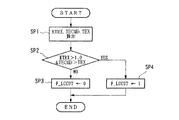
次いで、図2のフローチャートを参照してトルクコンバータがトルク増幅状態にあるか否かおよびそのトルク増幅率を検出するトルクコンバータ判断手段としての機能を中心として、ロックアップ解除判定手段5で行われる制御の内容を説明する。
ステップSP1 目標駆動力と現在のシフト位置とから必要タービントルクTTRを求める。
また、必要タービントルクTTRとトルクコンバータの入力軸回転数等から、ロックアップ解除時のトルコンスリップ率ETRXを求める。
次いで、このトルコンスリップ率ETRXとトルクコンバータのトルク増幅率との関係が予め記憶されたテーブルから、前記トルク増幅率であるトルク比KTRXを求める。
また、前記トルク比KTRXと前記必要タービントルクTTRとに基づいて要求エンジントルクTECMDを求める。
さらに、エンジン回転数NeとエンジントルクTeとの関係についてROM上に予め記憶されたトルク特性のテーブルから、現在の回転数において利用可能なエンジントルクの最大値である利用可能エンジントルクTEXを求める。この利用可能エンジントルクTEXは、図8に示すように、現在の回転数Neに対応する予め定められる設定値TEMAX(現在のシフト位置において仮にスロットルを全開相当とした場合に出力可能なエンジントルク)より低い値となり、通常は、この利用可能エンジントルクTEXにおいて最良のエンジン効率を得ることができる。
ステップSP2 KTRX>1およびTECMD>TEXの双方が成立するか否かを判断する。すなわち、トルクコンバータがトルク増幅領域にあり、しかも、要求エンジントルクTECMD(必要な駆動力を得るためにエンジンが与えるべきトルク)が利用可能エンジントルクTEXより大きいか否かを判断する。Noの場合にはSP3へ、Yesの場合にはSP4へ進む。
ステップSP3 ロックアップを解除すべき旨を表すLCCUTをクリアし、制御を終了する。
ステップSP4 ロックアップを解除すべき旨を表すLCCUTに1をセットし、制御を終了する。そして、FLCCUT=1となっている場合には、ロックアップ制御手段6がロックアップの締結を解除すべく、ロックアップクラッチを操作するアクチュエータを制御する。
【0012】
次いで、図3のフローチャートを参照して、前記シフトダウン判定手段7で行われる制御の内容をシフトダウン制御装置の動作とともに説明する。
ステップSP10 フラグLCCUTに1が立てられているか否かを判断し、Yesを条件としてステップ11へ進む。Noの場合にはシフトダウン制御は行われない。
ステップSP11 フラグ MTDN1に1が立てられているか否かを判断し、Noを条件としてステップSP12へ進む。Yesの場合には制御を終了する。このフラグ MTDN1は、シフトダウン制御がいかなる段階にあるかをフラグMTDN2とともに表すもので、これらのフラグがいかなる条件でセットされあるいはリセットされるかについては後述する。
ステップSP12 測定された速度が現在のシフト位置nより下のシフト位置n−1におけるダウンシフト限界車速VMAXn−1より大きいか否かを判断し、Noを条件としてステップSP13へ進み、Yesの場合にはステップSP5へ進む。前記VMAXは、変速機の機械的性能等に基づいて、各シフト位置毎に定められて所定の記憶領域へ予め記憶されたデータである。すなわち、シフトダウンすべきと判断された場合であっても、シフトダウン限界車速VMAXn−1より車速Vが大きい場合のシフトダウンを禁止することによって変速機の損傷等を防止するようになっている。
【0013】
ステップSP13 エンジン回転数NeとエンジントルクTeとの関係についてROM上に予め記憶されたトルク特性のテーブルから、現在の回転数に対応するエンジントルクの予め定められる設定値TEMAXを検索する。この設定値は、現在のシフト位置nにおいて、仮にスロットル制御手段によりスロットル開度を全開相当にした場合に出力可能なエンジントルクである。
ステップSP14 アクセルペダル開度APに基づいて決定された要求エンジントルクTECMDが前記選択されたTEMAXより大きいか否かを判断し、大きいことを条件としてステップSP16へ進み、Noの場合には、トルクに余裕があってシフトダウンが不要であるからステップSP15へ進んでフラグMTDN1およびMTDN2をクリアする。
ステップSP16 フラグMTDN2がセットされているか否かを判断し、Noの場合にはステップSP17へ、Yesの場合にはステップSP18へ進む。
【0014】
ステップSP17 以下の各種パラメータに所定の値を代入する。判断開始時点のアクセルペダル開度APBKD1にアクセルペダル開度APを代入する。ROMに予め記憶されたテーブルから、シフトダウン制御の実行および解除の判断基準となるアクセルペダル開度変化量ΔAPのしきい値DAPBKD1(実行時)および2(解除時)を検索する。
(一般に、速度が高いほど、加速のために必要なアクセルペダル開度が大きくなるから、DAPBKD1も大きな値となる)
前記アクセルペダル開度変化量ΔAPが増加方向へ変化する度にカウントアップされるカウンタのカウント値cTXKDをリセットする。
フラグMTDN1をクリアし、フラグMTDN2に1をセットする。
【0015】
ステップSP18 アクセルペダル開度変化量ΔAPが正であるか否かを判断し、Yesを条件としてステップSP19へ進む。Noの場合には、アクセルペダルをさらに踏み込んで加速する意志がないものと見なし、制御を終了する。
ステップSP19 前記カウンタのカウント値cTXKDをインクリメントする。
ステップSP20 前記カウント値cTXKDがしきい値LIMTXKDを越えるかを判断し、Yesを条件としてステップSP21へ進む。Noの場合には、アクセルペダル開度を上げる意志が小さいものと見なして(加速意志が小さいものと見なして)制御を終了する。
ステップSP21 前記判断開始時点のアクセル開度APBKD1およびアクセルペダル開度変化量ΔAPのしきい値DAPBKD1の和とアクセルペダル開度APとを比較し、アクセルペダル開度APがこれらの和より大きい場合には、ステップSP22へ進み、小さい場合には、シフトダウン不要と判断して制御を終了する。すなわち、アクセルペダル開度APがアクセルペダル開度変化量ΔAPのしきい値DAPBKD1以上に増大したことを条件として、シフトダウンを実行すべくSP22へ進む。
【0016】
ステップSP22 ダウンシフトを実行すべく各パラメータを以下のように設定する。シフト位置を示すパラメータSHIFTにSHIFT−1を設定する。すなわち、シフト位置を示すSHIFTの値から1を減ずることにより、1段下のシフト位置を示す値を設定する。
ダウンシフトが実行されている旨を示すフラグMTDN1に1をセットする。この結果、MTDN1がクリアされない限り、ステップSP11の判断がYesとなり、シフトダウン制御が行われないまま、SHIFT−1の位置に保持される。
シフトダウン実行時のアクセルペダル開度APをAPBKD2にセットする。
【0017】
一方、シフトホールドの解除動作を図4のフローチャートにより説明する。
ステップSP31において、解除判断アクセルペダル変化量APBKD2から解除判断のしきい値DAPBK2を減じた値と現在のアクセルペダル開度APとを比較し、アクセルペダル開度が所定の値を下回ったと判断された場合には、ステップSP32へ進み、フラグMTDN1およびMTDN2の双方をクリアする。したがって、ステップSP11における判断に基づくシフトダウン制御が可能な状態となって制御が終了する。すなわち、アクセルペダル開度APが所定以上にわたって小さくなった場合には加速意志が継続していないものと見なし、積算を中止すべく制御を終了する。また、下回らない場合には前記各フラグMTDN1およびMTDN2を操作することなく、ステップSP31の判断を繰り返す。
【0018】
前述の制御を実際のアクセルペダル開度変化を示す図5に沿って説明する。
t=0からアクセルペダル開度が大きくなり、t1においてTEMAXを超えると前記ステップSP17における処理によりフラグMTDN2に1がセットされる。MTDN2=1がセットされるため、ステップSP16〜ステップSP18〜ステップSP19の各ステップへ進み、cTXKDがカウントアップされる。すなわち、所定以上のアクセルペダル開度が維持され続けるとcTXKDがカウントアップされ続け、t2において、cTXKDがアクセルペダル開度積算しきい値LIMTXKDを超えたと判断される。このようなアクセルペダル開度の積算は、格別な装置を用いることなくソフトウエア上の処理によって容易に行うことができる。これに対して、運転者がアクセルの踏み込みを中止すると、cTXKDがカウントアップされないため、シフトダウンされることがなく、したがって、運転者の継続的な加速意志に基づいてのみシフトダウンが行われる。
なお、前述のような積算のやり方に代えて、アクセルペダルがしきい値を超えた旨が判断されることを条件としてクロックパルスをカウントし、このカウント値(アクセルペダルが所定以上に踏み込まれた以後の経過時間)をアクセルペダル開度積算値として用いるようにしてもよく、この場合も、ソフトウエア上の処理によって容易にアクセルペダル開度を積算することができる。
【0019】
さらに、ステップSP21において、アクセルペダル開度APが判断開始時点のアクセルペダル開度APBKD1を所定の値DAPBKD1以上に上回っていると判断されると、ダウンシフトを実行すべきと判断され、ステップSP22においてフラグMTDN1に1がセットされるとともに、ダウンシフトが実行される。以後、シフトホールド状態となる。したがって、エンジントルクに余裕がなく、シフトダウンが必要になった場合に、運転者の加速意志が継続していることを条件としてシフトダウンを行うから、運転者の加速意志に基づくシフトダウンによって良好なドライバビリティを発揮することができるとともに、過剰なシフト切り替えの発生を防止することができる。また、運転者の加速意志が強い場合に限って、シフトダウンすべきとの判断がなされる。さらに、t3において、アクセルペダル開度APが解除判断のしきい値DAPBKD2以上に減少すると、ステップSP31における判断に基づいてステップSP32で各フラグMTDN1および2がクリアされ、次回のシフトダウン制御への待機状態となる。
【0020】
以上の動作における前記フラグMTDN1および2の状態を整理すれば、図6に示すとおりである。すなわちシフトダウン制御が行われていない状態では、前記ステップSP22が実行されることによってこれらのフラグがともにクリア状態に維持され、エンジントルクTeがTEMAXを上回った後、シフトダウンが実行されるまではMTDN2のみに1がセットされ、さらに、シフトダウン実行後、アクセルペダル開度APの減少がDAPBKD2に達するまではMTDN1および2の双方に1がセットされる。
【0021】
なお、上記実施形態では現実のアクセルペダル開度の検出値APを用いて制御を行ったが、これに代えて、ファジー制御によって走行環境を推定し、推定された走行環境に基づいて修正されたアクセルペダル開度を用いてもよい。例えば、坂道走行の場合には実際のアクセルペダル開度より大きくアクセルペダル開度を調整すべく係数を乗じ、また、渋滞走行の場合には実際のアクセルペダル開度より小さくアクセルペダル開度を調整すべく係数を乗じることによって得られたアクセルペダル開度に基づいて制御を行うようにしてもよい。
【0022】
【発明の効果】
以上の説明で明らかなように、本発明のロックアップ制御装置は、エンジンの駆動力を伝達するトルクコンバータに並列に設けられたロックアップクラッチの締結およびその解除を制御するロックアップ制御装置において、前記締結および解除を実行すべくロックアップクラッチの駆動装置へ制御信号を出力するロックアップ制御手段と、アクセルペダル開度と車速とから車両の目標駆動力を算出する目標駆動力算出手段と、現在のシフト位置を検出するシフト位置検出手段と、トルクコンバータがトルク増幅状態にあるか否かおよびそのトルク増幅率を検出するトルクコンバータ判断手段と、前記目標駆動力とシフト位置とトルク増幅率とから目標エンジントルクを算出する算出手段と、目標エンジントルクをエンジンのトルク特性から予め定められる設定値と比較する比較手段と、この比較手段により、目標エンジントルクが前記設定値以上となっていると判断され、かつ、前記トルクコンバータ判断手段によりトルク増幅状態にある旨が判断されたことを条件として前記ロックアップ制御手段へロックアップ解除命令を出力するロックアップ解除判断手段とから構成したから、目標エンジントルクが設定値以上である場合、トルクコンバータ判断手段によってトルク増幅状態である旨の判断が行われたことを条件として、ロックアップが解除されることとなり、トルクコンバータのトルク増幅作用を有効に利用して、そのままのシフト位置でエンジントルクを最大限に発揮させることにより、ロックアップクラッチの締結解除を最小限にとどめて良好な燃費性能を得ることができる。
また、前記ロックアップが解除されたことを条件として、シフトダウンを行うか否かを判断するシフトダウン判定手段をさらに設けたから、トルクコンバータの増幅作用を利用してもなおトルクが不足する場合にシフトダウンを行って良好なドライバビリティを発揮することができる。
さらに、前記シフトダウン判定手段は、目標エンジントルクが前記設定値以上となっていることを条件としてアクセルペダル開度を積算し、積算された積算値がアクセルペダル開度積算しきい値を超えることを条件としてダウンシフトを命令するから、運転者の加速意志が継続している旨を確実に判断して、真に加速意志がある場合にのみシフトダウンを行い、いわゆるシフトビジーの発生を確実に防止することができる。
【図面の簡単な説明】
【図1】一実施形態のブロック図。
【図2】一実施形態におけるロックアップ解除処理のフローチャート。
【図3】一実施形態におけるシフトダウン制御実行処理のフローチャート。
【図4】一実施形態におけるシフトダウン制御解除処理のフローチャート。
【図5】一実施形態におけるシフトダウン制御のタイミングチャート。
【図6】一実施形態におけるフラグセットの条件を示す図表。
【図7】目標駆動力と速度とアクセルペダル開度との関係を示す図表。
【図8】エンジン回転に対応して予め定められるエンジントルクの設定値TEMAXと使用可能エンジントルクTEXとの関係を示す図表。
【符号の説明】
1 目標駆動力算出手段 2 シフト算出手段
3 演算器 4 スロットル制御手段
5 ロックアップ解除判定手段 6 ロックアップ制御手段
7 シフトダウン判定手段 8 シフト制御手段[0001]
TECHNICAL FIELD OF THE INVENTION
The present invention relates to a lock-up control device in a power transmission system of an automobile having an automatic transmission.
[0002]
[Prior art]
Conventionally, by using a torque converter and a lock-up clutch together, the power transmission efficiency is improved, and by adjusting the engagement force of the lock-up clutch according to the rotation state of the engine, the torque amplifying action of the torque converter ( There is known a lock-up control device which utilizes a deceleration effect. Further, the lock-up control device described in Japanese Patent Application Laid-Open No. 9-32915 determines whether the driver intends to accelerate from depression of an accelerator pedal or the like, and releases the engagement of the lock-up clutch when there is an intention to accelerate. Thus, the power is transmitted by the torque converter, and the torque amplifying action of the torque converter is used for acceleration. Further, according to this prior art, the acceleration performance is improved by utilizing the torque amplifying function of the torque converter as necessary, and the torque converter is designed to exhibit the maximum driving force based on the rate of change of the engine load. The acceleration performance is further improved by adjusting the reduction ratio (torque amplification ratio) of the motor.
[0003]
[Problems to be solved by the invention]
However, in order to efficiently transmit the driving force of the engine and obtain good fuel efficiency, it is necessary to keep the lock-up clutch in the engaged state as much as possible and to minimize the use of the torque amplifying effect of the torque converter by releasing the engagement. desirable.
Furthermore, when acceleration exceeding the torque obtained by the torque amplifying action of the torque converter as described above is required, downshifting is required to obtain the required torque, and depending on how this downshifting is performed, The acceleration performance of a car is greatly affected. Generally, a determination is made according to a shift map indicating an optimal shift position based on a relationship between a throttle opening and a vehicle speed, and a difference between a maximum torque and a target torque at the shift position is determined. Shift down is performed as necessary according to the determination to be made down. Here, if emphasis is placed on the determination according to the shift map, the shift down will not be performed unless the vehicle crosses the switching boundary on the shift map. descend. In addition, when emphasis is placed on the determination based on the surplus engine torque, the downshift is performed even for an instantaneous shortage of the engine torque, and the downshift generates the surplus engine torque and shifts up, and the switching is repeated ( (A so-called shift busy phenomenon).
[0004]
[Means for Solving the Problems]
The present invention has been made in view of the above circumstances, and it is possible to exhibit good acceleration performance by maximizing the torque amplifying action of a torque converter, and to minimize the disengagement of a lock-up clutch. Therefore, it is intended to obtain good fuel economy performance. Furthermore, even if the torque amplifying action of the torque converter is used, if the torque is still insufficient, downshifting can be performed reliably, good drivability can be exhibited, and the shift busy state is prevented. Aim.
[0005]
In order to achieve the above object, a lock-up control device according to
The lock-up control device according to
The lock-up control device according to a third aspect is characterized in that the shift-down determining means instructs a downshift based on the accelerator pedal opening on condition that the driver's intention to accelerate is continued.
A lock-up control device according to a fourth aspect of the present invention accumulates the number of times the amount of change in the accelerator pedal opening is positive, and sets the accelerator pedal opening at that time on the condition that the accumulated value exceeds a large threshold value. The degree is compared with a second threshold value, and a downshift is commanded on condition that the accelerator pedal opening at that time exceeds the second threshold value, and the acceleration intention is continued by the integration. The shift down is performed only when there is a true intention to accelerate, so that the occurrence of a so-called shift busy can be reliably prevented.
[0006]
BEST MODE FOR CARRYING OUT THE INVENTION
First, the configuration of the lockup control device of this embodiment will be described with reference to FIG.
[0007]
The signals of the target driving force and the shift position are supplied to an
[0008]
In addition,Required engine torque TECMDAre supplied to the lock-up release determination means 5. The lock-up release determination means 5 stores a table indicating the relationship between the rotation speed Ne and the available engine torque TEX, and stores information on the rotation speed Ne and the aforementioned information.Required engine torque TECMDBased on the information ofRequired engine torque TECMDIt is determined whether or not there is a margin for the available engine torque TEX with respect to. Further, the lock-up release determining means 5 stores data of the torque ratio of the torque converter, and determines whether the torque ratio of the torque converter is 1 or more at the rotation speed at which the lock-up is released. Then, the lock-up release determination means 5 supplies an instruction to the lock-up control means 6 as to whether or not the lock-up should be released based on each of the determinations. The lock-up control means 6 operates the lock-up clutch in order to control the degree of engagement of the lock-up clutch (the ratio between the power transmission by the lock-up clutch and the power transmission by the torque converter) according to the driving condition of the vehicle. A control signal is supplied to an actuator (for example, a hydraulic solenoid). Further, the lock-up control means 6 outputs a control signal to the actuator based on the determination of the lock-up release determination means 5 to release the engagement state.
[0009]
In addition,Required engine torque TECMDIs supplied to the downshift determination means 7. The shift-down determining means 7 further determines that the accelerator pedal opening AP and theRequired engine torque TECMDIt is determined on the basis of the above whether or not the downshift is necessary.
[0010]
When the downshift determining means 7 determines that a downshift should be performed, a downshift command is output from the downshift determining means 7 to the
[0011]
Next, with reference to the flow chart of FIG. 2, the control performed by the lock-up release determination means 5 mainly on the function as the torque converter determination means for detecting whether or not the torque converter is in the torque amplification state and for detecting the torque amplification rate. Will be described.
Step SP1 From the target driving force and the current shift positionRequired turbine torque TTRAsk for.
Also,Required turbine torque TTRWhenInput shaft speed of torque converter, etc.Then, the torque converter slip ratio ETRX at the time of lock-up release is obtained.
Next, the torque ratio KTRX, which is the torque gain, is determined from a table in which the relationship between the torque converter slip rate ETRX and the torque gain of the torque converter is stored in advance.
Also,A required engine torque TECMD is obtained based on the torque ratio KTRX and the required turbine torque TTR.
Further, the available engine torque TEX, which is the maximum value of the available engine torque at the current rotational speed, is obtained from the torque characteristic table stored in advance in the ROM regarding the relationship between the engine rotational speed Ne and the engine torque Te. As shown in FIG. 8, the available engine torque TEX is a predetermined set value TEMAX corresponding to the current rotational speed Ne (engine torque that can be output if the throttle is assumed to be fully open at the current shift position). Lower values usually result in the best engine efficiency at this available engine torque TEX.
Step SP2 KTRX> 1 andTECMD> TEX is determined. That is, the torque converter is in the torque amplification region, andRequired engine torque TECMD(The engine to get the necessary driving forceButIs determined to be larger than the available engine torque TEX. If No, the process proceeds to SP3, and if Yes, the process proceeds to SP4.
Step SP3: Clear the LCCUT indicating that the lockup should be released, and end the control.
Step SP4: Set 1 to LCCUT indicating that lockup should be released, and terminate the control. If FLCCUT = 1, the lock-up control means 6 controls the actuator that operates the lock-up clutch to release the lock-up engagement.
[0012]
Next, the contents of the control performed by the downshift determination means 7 will be described together with the operation of the downshift control device with reference to the flowchart of FIG.
Step SP10: It is determined whether or not 1 is set in the flag LCCUT, and the process proceeds to step 11 on condition of Yes. In the case of No, the downshift control is not performed.
Step SP11: It is determined whether or not 1 is set in the flag MTDN1, and the process proceeds to step SP12 on condition of No. In the case of Yes, the control ends. The flag MTDN1 indicates the stage of the shift down control together with the flag MTDN2, and the conditions under which these flags are set or reset will be described later.
Step SP12: It is determined whether or not the measured speed is higher than the downshift limit vehicle speed VMAXn-1 at the shift position n-1 below the current shift position n, and the process proceeds to step SP13 on condition of No, and in the case of Yes, Proceeds to step SP5. The VMAX is data determined for each shift position and stored in a predetermined storage area in advance based on the mechanical performance and the like of the transmission. That is, even when it is determined that the vehicle should be downshifted, damage to the transmission is prevented by prohibiting downshifting when the vehicle speed V is higher than the downshift limit vehicle speed VMAXn-1. .
[0013]
Step SP13: A predetermined set value TEMAX of the engine torque corresponding to the current rotational speed is retrieved from the torque characteristic table stored in advance in the ROM regarding the relationship between the engine rotational speed Ne and the engine torque Te. This set value is the engine torque that can be output if the throttle opening is equivalent to the full opening by the throttle control means at the current shift position n.
Step SP14: It is determined whether or not the required engine torque TECMD determined based on the accelerator pedal opening AP is larger than the selected TEMAX, and proceeds to step SP16 on condition that it is larger. Since there is room and the downshift is unnecessary, the process proceeds to step SP15 to clear the flags MTDN1 and MTDN2.
Step SP16: It is determined whether or not the flag MTDN2 is set. In the case of No, the flow proceeds to step SP17, and in the case of Yes, the flow proceeds to step SP18.
[0014]
Step SP17 Substitute predetermined values for the following various parameters. Accelerator pedal opening APBKD1 at the start of judgmentAccelerator pedal opening APIs assigned. From the table stored in the ROM in advance, the threshold values DAPBKD1 (during execution) and 2 (during cancellation) of the accelerator pedal opening change amount ΔAP, which are criteria for determining whether to execute or cancel the downshift control, are searched.
(Generally, the higher the speed, the larger the accelerator pedal opening required for acceleration, so the DAPBKD1 also has a larger value.)
SaidAccelerator pedal opening changeThe count value of the counter that is counted up each time ΔAP changes in the increasing directioncTXKDReset.
The flag MTDN1 is cleared, and the flag MTDN2 is set to 1.
[0015]
Step SP18: It is determined whether or not the accelerator pedal opening change amount ΔAP is positive, and the process proceeds to step SP19 on condition of Yes. In the case of No, it is considered that there is no intention to further depress the accelerator pedal to accelerate, and the control ends.
Step SP19: The count value cTXKD of the counter is incremented.
Step SP20: The count value cTXKD is equal to the thresholdLIMTTXKDIs determined, and the process proceeds to step SP21 on the condition of Yes. In the case of No, it is considered that the intention to increase the accelerator pedal opening degree is small (the acceleration intention issmallControl is terminated.
Step SP21Accelerator opening APBKD1 at the start of the judgmentandThreshold value DAPBKD1 of accelerator pedal opening change amount ΔAPIs compared with the accelerator pedal opening AP. If the accelerator pedal opening AP is larger than the sum, the process proceeds to step SP22. If the accelerator pedal opening AP is smaller, it is determined that downshifting is unnecessary and the control is terminated. That is, the accelerator pedal opening AP is equal to the accelerator pedal opening.Change amount ΔAPThe process proceeds to SP22 to execute the downshift, on condition that it has increased to the threshold value DAPBKD1 or more.
[0016]
Step SP22 Each parameter is set as follows to execute the downshift. SHIFT-1 is set in the parameter SHIFT indicating the shift position. In other words, the value indicating the shift position one step below is set by subtracting 1 from the value of SHIFT indicating the shift position.
The flag MTDN1 indicating that the downshift is being executed is set to 1. As a result, unless MTDN1 is cleared, the determination in step SP11 is Yes, and the shift-down control is not performed, and the shift-down control is held at the SHIFT-1 position.
The accelerator pedal opening AP at the time of executing the downshift is set to APBKD2.
[0017]
On the other hand, the shift hold release operation will be described with reference to the flowchart of FIG.
In step SP31, the value obtained by subtracting the release determination threshold value DAPBK2 from the release determination accelerator pedal change amount APBKD2 is compared with the current accelerator pedal opening AP, and it is determined that the accelerator pedal opening has fallen below a predetermined value. In this case, the process proceeds to step SP32, where both the flags MTDN1 and MTDN2 are cleared. Therefore, the shift-down control based on the determination in step SP11 is enabled and the control ends. That is, when the accelerator pedal opening AP has become smaller than a predetermined value, it is considered that the intention to accelerate is not continued, and the control is terminated to stop the integration. If not, the determination in step SP31 is repeated without operating the flags MTDN1 and MTDN2.
[0018]
The above control will be described with reference to FIG. 5 showing the actual change in the accelerator pedal opening.
When the accelerator pedal opening increases from t = 0, and exceeds TEMAX at t1, the flag MTDN2 is set to 1 by the processing in step SP17. Since MTDN2 = 1 is set, the process proceeds to each of steps SP16 to SP18 to SP19, and cTXKD is counted up. That is, if the accelerator pedal opening is maintained at a predetermined level or more, cTXKD continues to be counted up. At t2, it is determined that cTXKD has exceeded the accelerator pedal opening integrated threshold LIMTKDKD. Such accumulation of the accelerator pedal opening can be easily performed by software processing without using a special device. On the other hand, when the driver stops depressing the accelerator, cTXKD is not counted up, so that there is no downshift. Therefore, downshifting is performed only based on the driver's continuous acceleration intention.
Instead of the above-described manner of integration, clock pulses are counted on the condition that it is determined that the accelerator pedal has exceeded the threshold, and this count value (the accelerator pedal is depressed beyond a predetermined value) The elapsed time after this may be used as the integrated value of the accelerator pedal opening, and in this case also, the accelerator pedal opening can be easily integrated by processing on software.
[0019]
Further, in step SP21,Accelerator pedal opening APBKD1 at the start of determination of accelerator pedal opening APIs determined to be greater than or equal to the predetermined value DAPBKD1 or more, it is determined that downshifting should be performed, and in step SP22, the flag MTDN1 is set to 1 and downshifting is performed. Thereafter, a shift hold state is set. Therefore, when there is no margin in the engine torque and the downshift becomes necessary, the downshift is performed on the condition that the driver's intention to accelerate is continued. In addition to achieving excellent drivability, it is possible to prevent occurrence of excessive shift switching. Only when the driver has a strong intention to accelerate, it is determined that the driver should shift down. Further, at time t3, when the accelerator pedal opening AP decreases to the release determination threshold value DAPBKD2 or more, the flags MTDN1 and MTDN2 are cleared in step SP32 based on the determination in step SP31, and the process waits for the next downshift control. State.
[0020]
The state of the flags MTDN1 and MTDN2 in the above operation is summarized as shown in FIG. That is, in the state where the downshift control is not performed, both of these flags are maintained in the clear state by executing the step SP22, and the downshift is performed after the engine torque Te exceeds the TEMAX until the downshift is performed. Only 1 is set to MTDN2, and further, after execution of the downshift, 1 is set to both MTDN1 and 2 until the decrease of the accelerator pedal opening AP reaches DAPBKD2.
[0021]
In the above-described embodiment, the control is performed using the detected value AP of the actual accelerator pedal opening. However, instead of this, the driving environment is estimated by fuzzy control and corrected based on the estimated driving environment. The accelerator pedal opening may be used. For example, when traveling on a slope, multiply the coefficient to adjust the accelerator pedal opening larger than the actual accelerator pedal opening, and when congested, adjust the accelerator pedal opening smaller than the actual accelerator pedal opening Control may be performed based on the accelerator pedal opening obtained by multiplying the coefficient as much as possible.
[0022]
【The invention's effect】
As apparent from the above description, the lock-up control device of the present invention is a lock-up control device that controls engagement and disengagement of a lock-up clutch provided in parallel with a torque converter that transmits engine driving force. Lock-up control means for outputting a control signal to a drive device of a lock-up clutch for performing the engagement and disengagement; target drive force calculation means for calculating a target drive force of the vehicle from an accelerator pedal opening and a vehicle speed; Shift position detecting means for detecting a shift position of the torque converter, torque converter determining means for detecting whether or not the torque converter is in a torque amplification state, and a torque amplification rate thereof, and determining the target driving force, the shift position, and the torque amplification rate. Calculating means for calculating the target engine torque; and predicting the target engine torque from the torque characteristics of the engine. A comparing means for comparing with a predetermined set value, and the comparing means determines that the target engine torque is equal to or more than the set value, and that the torque converter determining means determines that the vehicle is in the torque amplification state. And a lock-up release determining means for outputting a lock-up release command to the lock-up control means on the condition that the torque converter is in a torque amplification state by the torque converter determining means when the target engine torque is equal to or greater than the set value. The lock-up will be released on condition that the judgment has been made, and by effectively utilizing the torque amplifying effect of the torque converter and maximizing the engine torque at the same shift position, the lock-up will be released. Good fuel economy performance with minimal up clutch disengagement Kill.
Further, a shift-down determination means for determining whether to perform a shift-down is further provided on condition that the lock-up is released, so that even when the torque is still insufficient even by utilizing the amplifying action of the torque converter. Good drivability can be exhibited by downshifting.
Further, the downshift determination means integrates the accelerator pedal opening on condition that the target engine torque is equal to or greater than the set value, and the integrated value exceeds the accelerator pedal opening integration threshold. The downshift is instructed on condition that it is determined that the driver's willingness to accelerate is continued, and downshifting is performed only when there is a true intention to accelerate. Can be prevented.
[Brief description of the drawings]
FIG. 1 is a block diagram of one embodiment.
FIG. 2 is a flowchart of lock-up release processing according to one embodiment.
FIG. 3 is a flowchart of downshift control execution processing according to one embodiment.
FIG. 4 is a flowchart of shift-down control release processing according to one embodiment.
FIG. 5 is a timing chart of downshift control in one embodiment.
FIG. 6 is a chart showing flag setting conditions according to the embodiment;
FIG. 7 is a chart showing a relationship between a target driving force, a speed, and an accelerator pedal opening.
FIG. 8 is a chart showing a relationship between a set value TEMAX of an engine torque predetermined according to an engine rotation and a usable engine torque TEX.
[Explanation of symbols]
1 target driving force calculating means 2 shift calculating means
3 arithmetic unit 4 throttle control means
5 Lock-up release determination means 6 Lock-up control means
7 shift down determination means 8 shift control means
Claims (4)
前記ロックアップクラッチの締結および解除を実行すべくロックアップクラッチの駆動装置へ制御信号を出力するロックアップ制御手段と、
前記ロックアップクラッチを解除した場合、解除した回転数においてトルクコンバータのトルク比が1以上かを判断するトルクコンバータ判断手段と、
アクセルペダル開度と車速とから車両の目標駆動力を算出する目標駆動力算出手段と、
シフト位置を検出するシフト位置検出手段と、
前記目標駆動力とシフト位置に対応する減速比とに基づいて、必要な目標エンジントルクを算出する目標エンジントルク算出手段と、
前記目標エンジントルクを実現するために必要なスロットル開度となるように制御されるスロットル制御手段と、
前記エンジンのトルク特性からエンジン回転数に対して利用可能なエンジントルクの最大値として予め定められている利用可能エンジントルクを求め、
前記目標エンジントルクを現在のエンジン回転数に対応する前記利用可能エンジントルクと比較する比較手段と、
前記比較手段により、前記目標エンジントルクが現在のエンジン回転数に対応する前記利用可能エンジントルクより大きいと判断され、且つ前記トルクコンバータ判断手段によりトルク比が1以上であると判断された場合に前記ロックアップ制御手段へロックアップ解除命令を出力するロックアップ解除判定手段と、
からなることを特徴とするロックアップ制御装置。In a lock-up control device that controls engagement and disengagement of a lock-up clutch provided in parallel with a torque converter that transmits a driving force of an engine,
Lock-up control means for outputting a control signal to a drive device of the lock-up clutch to execute engagement and disengagement of the lock-up clutch;
When the lock-up clutch is released, a torque converter determining unit that determines whether the torque ratio of the torque converter is 1 or more at the released rotation speed,
Target driving force calculating means for calculating a target driving force of the vehicle from the accelerator pedal opening and the vehicle speed,
Shift position detecting means for detecting a shift position;
A target engine torque calculating means for calculating a required target engine torque based on the target driving force and a reduction ratio corresponding to the shift position;
Throttle control means that is controlled to have a throttle opening required to achieve the target engine torque;
Obtain available engine torque that is predetermined as the maximum value of available engine torque for the engine speed from the torque characteristics of the engine,
Comparing means for comparing the target engine torque with the available engine torque corresponding to a current engine speed ;
When the comparing means determines that the target engine torque is larger than the available engine torque corresponding to the current engine speed , and the torque converter determining means determines that the torque ratio is 1 or more , Lock-up release determining means for outputting a lock-up release command to the lock-up control means,
A lock-up control device comprising:
Priority Applications (5)
| Application Number | Priority Date | Filing Date | Title |
|---|---|---|---|
| JP26906097A JP3580993B2 (en) | 1997-10-01 | 1997-10-01 | Lock-up control device |
| TW087116097A TW421698B (en) | 1997-10-01 | 1998-09-28 | Lock-up control device |
| US09/163,016 US6314357B1 (en) | 1997-10-01 | 1998-09-30 | Lock-up control device |
| EP98118572A EP0907043B1 (en) | 1997-10-01 | 1998-10-01 | Torque converter lock-up control device |
| DE69802882T DE69802882T2 (en) | 1997-10-01 | 1998-10-01 | Lock-up control device of a torque converter |
Applications Claiming Priority (1)
| Application Number | Priority Date | Filing Date | Title |
|---|---|---|---|
| JP26906097A JP3580993B2 (en) | 1997-10-01 | 1997-10-01 | Lock-up control device |
Publications (2)
| Publication Number | Publication Date |
|---|---|
| JPH11108175A JPH11108175A (en) | 1999-04-20 |
| JP3580993B2 true JP3580993B2 (en) | 2004-10-27 |
Family
ID=17467106
Family Applications (1)
| Application Number | Title | Priority Date | Filing Date |
|---|---|---|---|
| JP26906097A Expired - Fee Related JP3580993B2 (en) | 1997-10-01 | 1997-10-01 | Lock-up control device |
Country Status (5)
| Country | Link |
|---|---|
| US (1) | US6314357B1 (en) |
| EP (1) | EP0907043B1 (en) |
| JP (1) | JP3580993B2 (en) |
| DE (1) | DE69802882T2 (en) |
| TW (1) | TW421698B (en) |
Families Citing this family (27)
| Publication number | Priority date | Publication date | Assignee | Title |
|---|---|---|---|---|
| JP3696380B2 (en) * | 1997-08-27 | 2005-09-14 | 本田技研工業株式会社 | Shift-down control device |
| DE19963564A1 (en) * | 1999-12-29 | 2001-07-05 | Bosch Gmbh Robert | System for setting a transmission ratio in a transmission installed in a motor vehicle |
| JP2001330140A (en) * | 2000-05-22 | 2001-11-30 | Toyota Motor Corp | Control device for vehicular clutch |
| JP4119613B2 (en) * | 2001-01-11 | 2008-07-16 | ジヤトコ株式会社 | Automatic transmission lockup control device |
| US7604566B2 (en) * | 2007-03-02 | 2009-10-20 | Honda Motor Co., Ltd. | System and method of controlling a torque converter lockup clutch |
| US7854681B2 (en) * | 2007-04-30 | 2010-12-21 | Caterpillar Inc | System for controlling a machine with a continuously variable transmission |
| WO2009054256A1 (en) * | 2007-10-22 | 2009-04-30 | Komatsu Ltd. | Transmission control device and method for working vehicle |
| US8352138B2 (en) * | 2007-11-30 | 2013-01-08 | Caterpillar Inc. | Dynamic control system for continuously variable transmission |
| FR2933462B1 (en) * | 2008-07-04 | 2010-07-30 | Inst Francais Du Petrole | METHOD FOR CONTROLLING THE CLOSURE PHASE OF A CLUTCH OF A ROBOTIC AUTOMOTIVE TRANSMISSION SYSTEM |
| DE102008043106A1 (en) * | 2008-10-23 | 2010-04-29 | Zf Friedrichshafen Ag | Method for operating the lockup clutch in a power shift transmission of a work machine comprising at least one hydraulically actuated lifting device |
| DE102008043105A1 (en) * | 2008-10-23 | 2010-04-29 | Zf Friedrichshafen Ag | Method for actuating a clutch of a hydrodynamic torque converter |
| DE102008043109A1 (en) * | 2008-10-23 | 2010-04-29 | Zf Friedrichshafen Ag | A method of closing the lockup clutch in a power shift transmission of a work machine |
| DE102008043108A1 (en) * | 2008-10-23 | 2010-04-29 | Zf Friedrichshafen Ag | Method for actuating a clutch of a hydrodynamic torque converter |
| DE102008043107A1 (en) * | 2008-10-23 | 2010-04-29 | Zf Friedrichshafen Ag | Method for reversing the direction of travel of a vehicle |
| DE102008043110A1 (en) * | 2008-10-23 | 2010-04-29 | Zf Friedrichshafen Ag | Method for controlling a lockup clutch of a hydrodynamic torque converter |
| JP4923080B2 (en) * | 2009-03-27 | 2012-04-25 | ジヤトコ株式会社 | Continuously variable transmission and control method thereof |
| JP4779030B2 (en) | 2009-03-27 | 2011-09-21 | ジヤトコ株式会社 | Continuously variable transmission and control method thereof |
| JP4923079B2 (en) | 2009-03-27 | 2012-04-25 | ジヤトコ株式会社 | Continuously variable transmission and control method thereof |
| JP5027179B2 (en) | 2009-03-27 | 2012-09-19 | ジヤトコ株式会社 | Continuously variable transmission and control method thereof |
| JP5428528B2 (en) * | 2009-05-25 | 2014-02-26 | アイシン精機株式会社 | Vehicle control device |
| JP4914467B2 (en) | 2009-07-17 | 2012-04-11 | ジヤトコ株式会社 | Continuously variable transmission and control method thereof |
| JP5633557B2 (en) * | 2012-11-28 | 2014-12-03 | トヨタ自動車株式会社 | Travel control device |
| JP5733293B2 (en) * | 2012-11-28 | 2015-06-10 | トヨタ自動車株式会社 | Travel control device |
| JP2014104874A (en) * | 2012-11-28 | 2014-06-09 | Toyota Motor Corp | Traveling control device |
| US9267269B2 (en) | 2013-06-28 | 2016-02-23 | Komatsu Ltd. | Work vehicle and control method for same |
| DE102014009732B4 (en) * | 2014-06-28 | 2023-12-07 | Mercedes-Benz Group AG | Method for operating a motor vehicle powertrain having a torque converter lock-up clutch and an automatic transmission |
| JP6204445B2 (en) * | 2015-12-04 | 2017-09-27 | 株式会社Subaru | Vehicle control device |
Family Cites Families (18)
| Publication number | Priority date | Publication date | Assignee | Title |
|---|---|---|---|---|
| DE3212091C2 (en) * | 1982-04-01 | 1994-07-28 | Volkswagen Ag | Method for operating a drive unit for vehicles |
| JPS58200855A (en) * | 1982-05-20 | 1983-11-22 | Nissan Motor Co Ltd | Speed-change control method for v-belt type of stepless tansmission gear box |
| US4725951A (en) * | 1983-12-29 | 1988-02-16 | Nissan Motor Co., Ltd. | Control system for lock-up clutch in torque converter |
| JPS62103232A (en) * | 1985-10-30 | 1987-05-13 | Diesel Kiki Co Ltd | Clutch controller |
| US5035308A (en) * | 1987-10-01 | 1991-07-30 | Mazda Motor Corporation | Lock-up control system for automatic transmission |
| JP2843609B2 (en) * | 1989-09-09 | 1999-01-06 | ジャトコ株式会社 | Lock-up clutch operation control device |
| JPH03249474A (en) * | 1990-02-27 | 1991-11-07 | Mazda Motor Corp | Acceleration detector and engage force controller of fluid coupling using the same |
| US5221261A (en) | 1990-04-12 | 1993-06-22 | Schneider (Usa) Inc. | Radially expandable fixation member |
| US5496227A (en) * | 1990-04-18 | 1996-03-05 | Hitachi, Ltd. | Torque control method and apparatus for internal combustion engine and motor vehicles employing the same |
| US5274553A (en) * | 1991-05-09 | 1993-12-28 | Eaton Corporation | Torque converter slip rate based skip power downshift control strategy |
| JP2710080B2 (en) | 1991-09-14 | 1998-02-10 | 本田技研工業株式会社 | Control device for lock-up clutch of automatic transmission |
| JP3318945B2 (en) | 1992-03-02 | 2002-08-26 | 株式会社日立製作所 | Vehicle control device, vehicle control system and vehicle control method |
| JPH0694116A (en) | 1992-09-08 | 1994-04-05 | Hitachi Ltd | Automatic shift controller |
| US5475590A (en) * | 1993-10-22 | 1995-12-12 | Ford Motor Company | Automatic transmission torque converter bypass clutch control using engine torque compensation |
| JPH08178054A (en) * | 1994-12-26 | 1996-07-12 | Honda Motor Co Ltd | Control device for automobile |
| JPH08200493A (en) * | 1995-01-23 | 1996-08-06 | Nippon Soken Inc | Automatic transmission device |
| US5743829A (en) * | 1995-02-22 | 1998-04-28 | Honda Giken Kogyo Kabushiki Kaisha | Control system for vehicle automatic transmission |
| JP3127350B2 (en) | 1995-07-20 | 2001-01-22 | 本田技研工業株式会社 | Control device for lock-up clutch |
-
1997
- 1997-10-01 JP JP26906097A patent/JP3580993B2/en not_active Expired - Fee Related
-
1998
- 1998-09-28 TW TW087116097A patent/TW421698B/en not_active IP Right Cessation
- 1998-09-30 US US09/163,016 patent/US6314357B1/en not_active Expired - Fee Related
- 1998-10-01 DE DE69802882T patent/DE69802882T2/en not_active Expired - Fee Related
- 1998-10-01 EP EP98118572A patent/EP0907043B1/en not_active Expired - Lifetime
Also Published As
| Publication number | Publication date |
|---|---|
| TW421698B (en) | 2001-02-11 |
| EP0907043A1 (en) | 1999-04-07 |
| US6314357B1 (en) | 2001-11-06 |
| DE69802882D1 (en) | 2002-01-24 |
| JPH11108175A (en) | 1999-04-20 |
| EP0907043B1 (en) | 2001-12-12 |
| DE69802882T2 (en) | 2002-06-20 |
Similar Documents
| Publication | Publication Date | Title |
|---|---|---|
| JP3580993B2 (en) | Lock-up control device | |
| US7149616B2 (en) | Control apparatus and method for vehicle | |
| US5669850A (en) | Shift hunting prevention for an automatic transmission | |
| JP2576240B2 (en) | Control device for semi-automatic transmission | |
| US5685801A (en) | Cruise control overspeed reduction with automatic transmission | |
| US5778331A (en) | Kickdown delay in cruise control for automatic transmission | |
| JP3696380B2 (en) | Shift-down control device | |
| US20060111220A1 (en) | Vehicle control device | |
| JP4698836B2 (en) | Control method of automatic transmission | |
| US6212458B1 (en) | Adaptive brake compensation for grade braking | |
| EP0924415A2 (en) | Throttle controller for limiting degree of opening of throttle in stall state | |
| JP4670208B2 (en) | Vehicle control device | |
| JP3900773B2 (en) | Shift control device for automatic transmission | |
| JP2700546B2 (en) | Control device for automatic transmission | |
| JP2005075179A (en) | Control device for vehicle | |
| US5975262A (en) | Lock-up clutch control apparatus | |
| US6689017B2 (en) | Shift control apparatus for an automatic transmission and shift control method for an automatic transmission | |
| JP4910298B2 (en) | Shift control device for automatic transmission | |
| JP2523450B2 (en) | Engine throttle valve control device | |
| JP2958580B2 (en) | Shift control device for automatic transmission for vehicle | |
| JP2523451B2 (en) | Engine throttle valve control device | |
| JP2005114040A (en) | Controller of vehicle | |
| JP3102278B2 (en) | Control device for automatic transmission for vehicle on downhill road | |
| JP4129714B2 (en) | Shift control device for automatic transmission | |
| JP3612772B2 (en) | Automatic transmission control device |
Legal Events
| Date | Code | Title | Description |
|---|---|---|---|
| A131 | Notification of reasons for refusal |
Free format text: JAPANESE INTERMEDIATE CODE: A131 Effective date: 20040217 |
|
| A521 | Written amendment |
Free format text: JAPANESE INTERMEDIATE CODE: A523 Effective date: 20040413 |
|
| A131 | Notification of reasons for refusal |
Free format text: JAPANESE INTERMEDIATE CODE: A131 Effective date: 20040601 |
|
| A521 | Written amendment |
Free format text: JAPANESE INTERMEDIATE CODE: A523 Effective date: 20040623 |
|
| TRDD | Decision of grant or rejection written | ||
| A01 | Written decision to grant a patent or to grant a registration (utility model) |
Free format text: JAPANESE INTERMEDIATE CODE: A01 Effective date: 20040713 |
|
| A61 | First payment of annual fees (during grant procedure) |
Free format text: JAPANESE INTERMEDIATE CODE: A61 Effective date: 20040721 |
|
| R150 | Certificate of patent or registration of utility model |
Free format text: JAPANESE INTERMEDIATE CODE: R150 |
|
| FPAY | Renewal fee payment (event date is renewal date of database) |
Free format text: PAYMENT UNTIL: 20080730 Year of fee payment: 4 |
|
| FPAY | Renewal fee payment (event date is renewal date of database) |
Free format text: PAYMENT UNTIL: 20090730 Year of fee payment: 5 |
|
| LAPS | Cancellation because of no payment of annual fees |