JP3577236B2 - Gas supply control device - Google Patents
Gas supply control device Download PDFInfo
- Publication number
- JP3577236B2 JP3577236B2 JP06525599A JP6525599A JP3577236B2 JP 3577236 B2 JP3577236 B2 JP 3577236B2 JP 06525599 A JP06525599 A JP 06525599A JP 6525599 A JP6525599 A JP 6525599A JP 3577236 B2 JP3577236 B2 JP 3577236B2
- Authority
- JP
- Japan
- Prior art keywords
- pressure
- control device
- sensor
- orifice
- flow rate
- Prior art date
- Legal status (The legal status is an assumption and is not a legal conclusion. Google has not performed a legal analysis and makes no representation as to the accuracy of the status listed.)
- Expired - Fee Related
Links
Images

Description
【0001】
【発明の属する技術分野】
本発明は、絞り部の圧力流量特性を利用したガス供給制御装置に関し、特に、絞り部の有効断面積を熱式流量センサにより検知し、流体流量を制御するガス供給制御装置に関するものである。
【0002】
【従来の技術】
従来、半導体製造装置において、例えば、ウエハ表面に薄膜を形成させるCVD装置では、薄膜材料を構成する化合物からなる1種又は数種の材料ガスをウエハ上に供給している。このとき、ウエハ表面に形成される薄膜を所望のものにする(例えば、薄膜の厚さを均一にする)ために、ウエハ上に供給される材料ガスを一定量連続して供給させる必要がある。
【0003】
そこで、CVD装置においては、ウエハ上に供給される材料ガスを一定量連続して供給させるガス供給制御装置が使用されている。かかるガス供給制御装置には、マスフローコントローラが使用されていた。しかし、近年の微細加工の要求に応えるには、マスフローコントローラは応答性が鈍く、しかも低流量領域における制御精度が悪いという問題があった。
【0004】
この問題を解決するために、特開平10−55218号公報に記載されたガス供給制御装置は、マスフローコントローラに換えて音速ノズルを使用したガス供給制御装置を提案している。
特開平10−55218号公報に記載されたガス供給制御装置は、直径0.2mmの丸穴が形成された金属薄板からなるオリフィスを使用している。そして、かかるオリフィスの下流側の圧力P2に対するオリフィスの上流側の圧力P1の比P1/P2が約1.4より大きい場合に、オリフィスを音速流で通過する材料ガスの流量Qcが、
Qc=K×S×P1
(但し、Kは定数、Sは有効断面積)のベルヌーイの式で近似される、オリフィスの圧力流量特性を利用するものである。
【0005】
従って、材料ガスが音速流にあり、オリフィスの下流側の圧力P2に対するオリフィスの上流側の上流圧力P1の比P1/P2 が約1.4より大きければ、一次圧力検出器で検出されるオリフィスの上流側の圧力P1に基づいて、オリフィスを通過する材料ガスの流量Qcを算出することができる。また、オリフィスの上流側の圧力P1を、オリフィスの上流側に配設された圧力制御バルブで調節することにより、オリフィスを通過する材料ガスの流量Qcを設定値に保つことができる。
【0006】
【発明が解決しようとする課題】
しかしながら、特開平10−55218号公報に記載されたガス供給制御装置には、次のような問題があった。
(1)腐食性の高い材料ガスを使用すると、オリフィスの丸穴が腐食し、腐食部分が流体圧力により吹き飛ばされ、拡径する場合があった。また、上流側流路内に発生したパーティクルが、オリフィスの丸穴周辺に付着し、丸穴が目詰まりする可能性があった。
このとき、丸穴の直径が僅かに変化しただけで、オリフィスを通過する材料ガスの流量が大きく変化する。例えば、オリフィスの丸穴が変形する前の上流側圧力P1を10Pa、オリフィスを通過する材料ガスの流量Qを250cc/secとすると、オリフィスの直径が僅か0.2mmから0.21mmに(5%)拡径しただけで、流量は10.25%増加して、約275.6cc/secとなり、約25cc/secも増加する。
このように有効断面積の変化は流体流量を大きく変化させるので、特に微細加工の場合には、製品が粗悪になり、深刻な問題である。それにもかかわらず、特開平10−55218号公報に記載されたガス供給制御装置には、オリフィスの径の拡大や目詰まり等による有効断面積Sの変化を検出するシステムが設けられていなかった。従って、オリフィスを取り外して点検しなければ、有効断面積の変化、すなわち、オリフィスの故障を発見することができなかった。
【0007】
(2)しかも、特開平10−55218号公報に記載されたガス供給制御装置は、上述した流量Qcの算出式において、有効断面積Sを予め所定値に設定し、定数的に取り扱っていた。
従って、特開平10−55218号公報に記載されたガス供給制御装置は、上述した算出式に対して有効断面積Sの変化を補うことができないので、オリフィスが交換を要しない程に劣化している場合に、材料ガスの流量を精度よく制御することができないという問題があった。
【0008】
(3)また、特開平10−55218号公報のオリフィスは、ねじにより弁本体に取り付けられていたため、ガス供給制御装置の構造が大型化していた。このため、オリフィスからオリフィスの下流に配設された最終遮断バルブまでの流路面積が大きく、一定時間最終バルブを閉鎖した後に、再度最終バルブを開放すると、オーバーシュートが発生する問題があった。
すなわち、最終遮断バルブが閉鎖されても、オリフィスの下流側圧力P2は上流側圧力P1よりも小さいため、材料ガスが上流側から下流側へ供給され続ける。そのため、オリフィス33の下流側に蓄積された材料ガスは、所定の圧力値よりも大きくなる。その後、再度最終遮断バルブを開放すると、下流側に蓄積された材料ガスが一気にチャンバへ流れ込み、オーバーシュートを発生する。このようなオーバーシュートは、オリフィスから最終遮断バルブまでの流路面積が大きいほど、顕著に発生する。
また、オーバーシュートが発生すると、流量は振動しながら目標値に整定されるため、応答時間が長くなり、問題であった。
【0009】
そこで、本発明は、上述した問題点を解決するためになされたものであり、絞り部を取り外さなくても絞り部の故障を検出することができ、絞り部の有効断面積の変化と絞り部の上流側圧力の変化に基づいて、精度よく流体流量を制御することができるコンパクトなガス供給制御装置を提供することを目的とする。
【0010】
【課題を解決するための手段】
(1)本発明のガス供給制御装置は、流体を音速で連続して通過させる絞り部と、前記絞り部の上流側で流体圧力を検出する圧力センサと、前記絞り部の上流側で流体温度を検出する温度センサと、前記絞り部の圧力を調節する圧力制御バルブとを有し、前記圧力センサ及び温度センサの検出結果に基づいて前記圧力制御バルブを制御することにより、流体供給量を制御するガス供給制御装置であって、前記絞り部を通過する流体の流量を検出する熱式流量センサと、前記圧力センサと前記温度センサの検出結果に基づいて算出された前記絞り部に供給される流量と、前記熱式流量センサが検出する流量との差を求め、その差が許容範囲を超えたときに、前記絞り部が故障したと判断する比較回路と、を有する。
【0011】
(2)また、本発明のガス供給制御装置は、(1)に記載するガス供給制御装置であって、前記圧力センサ及び温度センサの検出結果に基づいて、前記絞り部を通過する流体流量を算出する第1演算回路と、前記熱式流量センサの検出結果に基づいて、前記絞り部の有効断面積を算出する第2演算回路と、前記絞り部を通過する流体の流量設定値が入力された制御回路とを有し、前記第2演算回路の第2算出結果が、前記圧力センサの検出結果を補正し、前記第1演算回路が、前記補正後の圧力センサの検出結果を利用して流体流量を算出して、その第1算出結果を前記制御回路へ送信する。
【0012】
(3)また、本発明のガス供給制御装置は、(1)又は(2)のいずれかに記載するガス供給制御装置であって、前記熱式流量センサの検出結果に基づいて警告信号を発する比較回路を有する。
【0013】
(4)また、本発明のガス供給制御装置は、(1)乃至(3)のいずれか一つに記載するガス供給制御装置であって、前記熱式流量センサ、前記圧力センサ及び前記温度センサを、同一カバー内に収納する。
【0014】
(5)また更に、本発明のガス供給制御装置は、(1)乃至(4)のいずれか一つに記載するガス供給制御装置であって、前記絞り部を、前記流体供給量を調節する最終遮断バルブの入口ポートに近傍に設けた。
【0015】
以下、上記構成を有するガス供給制御装置の作用について説明する。
流体が音速流で通過する絞り部は、マスフローコントローラとは異なり、高流量領域、中流量領域及び低流量領域の各領域において、測定精度が優れており、しかも、構造がシンプルであるため故障が生じにくいという利点があることが、一般に知られている。
【0016】
そこで、本発明のガス供給制御装置は、絞り部の下流側圧力P2に対する上流側圧力P1の比P1/P2が一定値以上になるように全体を制御し、流体が音速流で絞り部を通過するようにしている。
音速流で絞り部を通過する流体には、下流側圧力P2の変動が上流側に伝播しないため、絞り部を通過する流体の流量を上流側圧力P1のみで検出できるという圧力特性がある。
【0017】
本発明のガス供給制御装置は、上記流体の圧力特性を利用するものである。すなわち、ガス供給制御装置は、第1演算回路において、絞り部を音速流で通過する流体の圧力特性を利用して、ベルヌーイの式で近似される第1算出式、すなわち、
Q=K×S×P1×(273/T1)1/2
(但し、Kは定数、Sは絞り部の有効断面積、T1は絞り部の上流温度)から、絞り部を音速流で通過する流体の流量Qを算出する。
【0018】
これによると、圧力センサで検出される絞り部の上流側の圧力検出結果P1と、温度センサで検出される絞り部の上流側の温度検出結果T1とに基づいて、絞り部を音速流で通過する材料ガスの流量Qを算出することができる。また、絞り部の上流圧力P1を上流圧力制御バルブで調節することにより、絞り部を音速流で通過する流体の流量Qを設定値に保つことができる。
【0019】
しかし、ガス供給制御装置が制御する流体として、腐食性の高い流体を長時間使用した場合に、絞り部の流路が腐食され、腐食部分が流体圧力により吹き飛ばされて流路が拡径したり、パーティクルが流路に目詰まりするなどして、絞り部の有効断面積が変化する可能性がある。
【0020】
そこで、本発明は、有効断面積の変化を検出するべく、熱式流量センサを絞り部の上流側に配設した。
熱式流量センサには、応答性が悪く、しかも低流量領域における精度が悪いという欠点がある。しかし、絞り部を通過する流体の流量は、僅かな絞り部の有効断面積の変化により大きく変化する。例えば、絞り部の流路が丸穴である場合、丸穴の径が0.2mmから0.21mmに拡径しただけで、流量は10.25%増加する。また、熱式流量センサは、流量の変化から絞り部の有効断面積の変化を検出し、絞り部の故障を検出するものであるから、低流量領域でないときに流量を測定し、絞り部の故障を発見すればよい。
従って、本発明のガス供給制御装置においては、上記熱式流量センサの欠点は問題とならない。
【0021】
熱式流量センサは、ガス供給制御装置が作動している間、絞り部を音速流で通過する流体の流量を検出する。そして、熱式流量センサの流量検出結果Q’は、第2演算回路へ送信される。第2演算回路は、第2算出式、すなわち、
S’=(T1/273)1/2*Q’/KP1
(但し、Kは定数、Q’は熱式流量センサが検出した流量、T1は絞り部の上流温度)から、絞り部の有効断面積S’を算出する。
【0022】
第2算出式の第2算出結果S’は、第1演算回路へ送られる。そして、第2算出結果S’は、第1演算回路が受信した圧力センサの圧力検出結果を補正する。すなわち、第2算出結果S’がしきい値を上回る場合には、有効断面積が拡大しているので、圧力センサの圧力検出結果を小さくする補正を行う。また、第2算出結果S’がしきい値を下回る場合には、有効断面積が縮小しているので、圧力センサの圧力検出結果を大きくする補正を行う。
【0023】
第1演算回路は、上記のように補正された圧力センサの圧力検出結果P1と、温度センサの検出結果T1とを第1算出式に代入し、絞り部に供給される流体の流量を算出する。また、第1演算回路は、第2算出結果S’がしきい値と等しい場合には、圧力センサの検出結果をそのまま第1算出式に代入し、絞り部に供給される流体の流量を算出する。
よって、作業中に僅かに有効断面積が変化した場合であっても、絞り部へ供給される流体の流量を正確に制御することができる。
【0024】
第1演算回路で算出された第1算出結果Qは、比較回路及び制御回路へ送られる。
比較回路は、第1演算回路42で算出された第1算出結果Qと、熱式流量センサの検出結果Q’とを受信する。そして、比較回路は、第1算出結果Qと熱式流量センサの検出結果Q’とを比較し、両者の差が許容範囲を超えた場合には、外部に警報信号を発信し、絞り部の異常を知らせる。
よって、作業中に絞り部に故障が発生しても、その時点で絞り部を交換するなどして故障に対処することができるので、絞り部が故障したまま作業を継続することがなく、歩留まり率が向上する。
【0025】
一方、制御回路には、あらかじめ流量設定値が入力されている。制御回路は、第1算出結果Qが流量設定値に近づくように、圧力制御バルブの開度を調節する。すなわち、第1算出結果Qが流量設定値よりも大きい場合には、圧力制御バルブを閉鎖する方向に制御し、流量を減少させる。一方、第1算出結果Qが流量設定値よりも小さい場合には、圧力制御バルブを開放する方向に制御し、流量を増加させる。
このように、圧力制御バルブが、絞り部の上流側圧力P1を常に最適の開度で調節するので、流体を一定量連続して供給し続けることができる。
【0026】
ここで、更に流体流量を正確に制御するためには、絞り部の位置が重要である。すなわち、ガス供給制御装置をコンパクト化し、絞り部から最終遮断遮断バルブまでの距離を小さくして、オーバーシュートの発生を防止することが必要である。
そこで、本発明のガス供給制御装置は、圧力センサ、温度センサ及び熱式流量センサを同一カバー内に収納して、センサパックとすることにより、ガス供給制御装置自体をコンパクト化した。
また、制御不能領域を縮小するために、本発明のガス供給制御装置は、最終遮断バルブの入口ポートに絞り部を配設している。
【0027】
【発明の実施の形態】
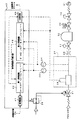
以下、本発明の実施の形態を図面を参照して説明する。図1は、半導体製造のウエハ処理工程における、CVD装置を使用した薄膜形成のラインの一部であって、本実施の形態のガス供給制御装置を備えたものを示したブロック図である。
【0028】
チャンバ30は、真空ポンプ31によって減圧状態に保たれるものである。そして、チャンバ30と真空ポンプ31の間には、チャンバ30の減圧状態を電気信号で制御する下流圧力制御バルブ20と、チャンバ30と真空ポンプ31を遮断する遮断バルブ10が設けられている。
【0029】
チャンバ30には、最終遮断バルブ11を介して、ウエハ表面の薄膜材料を構成する一種類の元素からなる材料ガスが供給される。かかる材料ガスを、図1の半導体製造のウエハ処理工程においては、一定量連続してチャンバ30内に供給することによって、ウエハ表面に所望の薄膜を形成させている。
ここで、材料ガスとして、一種または数種の化合物ガスを使用する場合もある。
【0030】
チャンバ30に一定量の材料ガスを連続して供給するため、最終遮断バルブ11の上流側には、材料ガスの流量調節を行うガス供給制御装置が設けられている。ガス供給制御装置は、圧縮空気で駆動される圧力制御バルブ21、熱式流量センサ36、温度センサ35、圧力センサ34、中央に直径0.2mmの孔が設けられた金属薄板からなるオリフィス33などを備え、コントローラ40で制御される。
【0031】
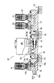
図2は、かかるガス供給制御装置の具体例を断面図で示したものである。
図2に示すように、ガス供給制御装置は、圧力制御バルブ21、温度センサ35、熱式流量センサ36、圧力センサ34及び最終遮断バルブ11を有している。図1には図示されていないが、圧力制御バルブ21と圧力センサ34との間には、パージ弁23が配設されている。
【0032】
図2に示すように、圧力制御バルブ21及びパージ弁23は、上方からねじで第1固定ブロック13に固設されている。第1固定ブロック13の図中左側面には、第1流路変更ブロック16が接続されている。
圧力制御バルブ21は、耐熱用樹脂であるロッドパッキン22を除くほか、その内部は全て金属で構成されている。また、圧力制御バルブ21は、図1に示すように、電−空レギュレータ39を介して送られる圧縮空気により駆動される。よって、圧力制御バルブ21は、耐熱性能に優れている。
【0033】
図2に示すように、温度センサ35、熱式流量センサ36及び圧力センサ34は、第2固定ブロック14の図中上側面に固設されている。第2固定ブロック14の図中左右側面には、第2、第3流路変更ブロック17、18が接続されている。また、これらのセンサは同一カバー38内に収納されて、センサパック37を構成している。
【0034】
ここで、圧力センサ34は、1.0×10⁻¹〜1.0×10⁵ Paを測定範囲とするピラニ真空計である。また、温度センサ35については、圧力センサ34であるピラニ真空計の温度測定機能を使用している。
しかし、圧力センサ34として、金属抵抗歪みセンサ、半導体抵抗歪みセンサ、可変容量形圧力センサ等を使用してもよい。また、温度センサ35として、熱電形温度センサ、金属抵抗温度センサ、サーミスタ等を使用してもよい。
【0035】
最終遮断バルブ11は、第3固定ブロック15の図中上側面に上方からねじで固定されている。第3固定ブロック15には、第1、第2流路15a、15bが形成されている。第1流路15aは、オリフィスブロック12を介して、最終遮断バルブ11の入口ポート11aに連通している。
オリフィスブロック12の中央部には流路が形成され、その一端には、オリフィス33が設けられている。オリフィスブロック12は、オリフィス33が入力ポート11aに面するように配設されている。
また、第2流路15bは、最終遮断バルブ11の出口ポート11bに連通している。
【0036】
第1連結ブロック24は、第1流路変更ブロック16及び第2流路変更ブロック17に連結し、第2連結ブロック25は、第3流路変更ブロック18及び第3固定ブロック15に連結している。これにより、圧力制御バルブ21、センサパック37及び最終遮断バルブ11は一体化されている。
【0037】
図1に示すように、コントローラ40には、流量設定値Qxを入力され、圧力制御バルブ21に制御信号を送信する制御回路41と、オリフィス33を通過する材料ガスの流量を算出する第1演算回路42と、オリフィス33の流路面積(以下、有効断面積という)を算出する第2演算回路43と、流量異常アラームを発する比較回路44が設けられている。
【0038】
次に、図1を参照しながら、ガス供給制御装置が、材料ガスをチャンバ30に一定量連続して供給し、その供給量を制御する仕組みについて説明する。
本実施の形態のガス供給制御装置は、オリフィス33の下流側圧力P2に対する上流側圧力P1の比P1/P2を一定値以上に維持するよう、全体を制御している。このように、全体を制御するのは、以下の理由による。
【0039】
オリフィス33の上下流の圧力比P1(上流)/P2(下流)を一定値以上に維持することにより、材料ガスがオリフィス33を音速流で通過する。材料ガスがオリフィス33を音速流で通過すると、下流側圧力P2の圧力変動が上流側に伝播しない。よって、オリフィス33の上下流の圧力比P1(上流)/P2(下流)を一定値以上に維持すると、オリフィス33を音速流で通過する材料ガスの流量Qを、上流側圧力P1に基づいて制御することができる。
本実施の形態においては、オリフィス33の下流側圧力P2に対する上流側圧力P1の比P1/P2を約2.8以上に設定している。
【0040】
このような材料ガスの圧力特性を利用して、第1演算回路42は、ベルヌーイの式に近似する第1算出式から、オリフィス33に供給される材料ガスの流量Qを算出している。すなわち、第1演算回路は、
Q=K×S×P1×(273/T1)1/2
(但し、Kは定数、Sはオリフィス33の有効断面積、T1はオリフィス33の上流温度)から、オリフィス33を音速流で通過する材料ガスの流量Qを算出している。
【0041】
ここで、ガス供給装置に長時間腐食ガスを使用すると、オリフィス33が腐食して流路が拡径したり、オリフィス33の流路にパーティクルが目詰まりするなどして、有効断面積が変化する場合がある。
この有効断面積の変化を検出するため、本実施の形態のガス供給制御装置は、熱式流量センサ36をオリフィス33の上流側に配設している。すなわち、熱式流量センサ36が、オリフィス33を音速流で通過する材料ガスの流量Q’を、検出し、その流量変化から有効断面積の変化を検出するのである。
【0042】
ここで、熱式流量センサ36には、応答性が悪く、しかも低流量領域においては精度が悪いという欠点がある。
しかし、オリフィス33を通過する材料ガスの流量Q’は、オリフィス33の有効断面積が僅かに変化しただけで、大きく変化する。例えば、オリフィス33の流路の径が直径0.2mm、上流側圧力P1が10Paであって、オリフィス33を通過する材料ガスの流量Qが250cc/secであると仮定する。そして、上流側圧力P1が10Paであって、オリフィス33の流路の直径が僅か0.2mmから0.21mmに(5%)拡径した場合、有効断面積は10.25%増加する。有効断面積の増加に伴い、流量Q’も10.25%増加して、約275.6cc/secとなり、約25cc/sec増加する。
よって、熱式流量センサ36は、微妙な流量変化を検出しなくても、有効断面積の変化を検出することができる。
【0043】
また、熱式流量センサ36は、流量の変化からオリフィス33の故障を検出することを目的としているので、常に材料ガスの流量を検出する必要はない。よって、熱式流量センサ36は、低流量でないときに、オリフィス33を通過する材料ガスの流量Q’を検出し、オリフィス33の故障を検出すればよい。
従って、上記熱式流量センサの欠点は、本実施の形態においては何ら問題とならない。
【0044】
よって、第2演算回路43は、熱式流量センサ36の流量検出結果Q’に基づいて、第2算出式、すなわち、
S’=Q’/KP1*(T1/273)1/2
(但し、Kは定数、Q’は熱式流量センサ36が検出した流量、T1はオリフィス33の上流温度)から、オリフィス33の有効断面積を算出する。
そして、第2演算回路43は、この第2算出結果S’を第1演算回路42へ送信する。
【0045】
第2算出結果S’は、圧力センサ34の圧力検出結果P1を補正する。すなわち、第2算出結果S’がしきい値を上回る場合には、オリフィス33の有効断面積が拡径しているので、圧力センサ34の圧力検出結果P1を小さくする補正を行う。一方、第2算出結果S’がしきい値を下回る場合には、オリフィス33の有効断面積が小径となっているので、圧力センサ34の圧力検出結果P1を大きくする補正を行う。また、第2算出結果S’がしきい値に等しい場合には、圧力センサ34の補正を行わない。
【0046】
そして、適正値に補正された圧力センサ34の圧力検出結果P1を第1算出式に代入して、オリフィスへ供給される材料ガスの流量Qが算出される。
よって、有効断面積の変化に応じて圧力センサ34の圧力検出結果P1を適正値に補正するので、作業中に有効断面積が変化しても、オリフィス33へ供給される材料ガスの流量Qが一定となり、チャンバ30内の材料ガスの濃度を所定値に維持することができる。これにより、不良品の数が減少し、歩留まり率が向上する。
【0047】
第1算出結果Qは、制御回路41と比較回路44へ送信される。
制御回路41には、流量設定値Qxが入力されている。そして、制御回路41は、第1算出式から算出された第1算出結果Qが、流量設定値Qxに近づくように、圧力制御バルブ21の開度を制御して、オリフィス33の上流側圧力P1を調節する。
【0048】
圧力制御バルブ21の開度の調節は、電−空レギュレータ39に制御信号を発信して、圧力制御バルブ21の駆動源である圧縮空気の供給量を調節することによって行う。すなわち、第1算出結果Qが流量設定値Qxよりも大きい場合には、圧力制御バルブ21を閉鎖する方向に制御し、上流側圧力P1を減圧する。一方、第1算出結果Qが流量設定値Qxよりも小さい場合には、圧力制御バルブ21を開放する方向に制御し、上流側圧力P1を増圧する。
これにより、ガス供給制御装置は、チャンバ30内に材料ガスを一定量連続して供給し、チャンバ30内の材料ガスの濃度が所定値に維持されるので、不良品の数が減少し、歩留まり率が向上する。
【0049】
また、比較回路44は、第1算出結果Qと熱式流量センサの検出結果Q’とを受信する。そして、比較回路は、第1算出結果Qと熱式流量センサの検出結果Q’とを比較し、両者の差が許容範囲を超えた場合には、外部に流量異常アラームを発し、オリフィス33の故障を知らせる。
よって、作業者は、オリフィス33が交換を要するほどに劣化したことを流量異常アラームにより確認することができるので、その時点でオリフィス33を交換する等して故障に対処することができる。これにより、オリフィス33が故障したまま作業を継続することがなく、歩留まり率が向上する。
【0050】
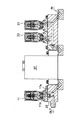
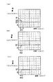
ところで、発明者らは、ガス供給制御装置の精度を更に向上させるために、オリフィス33の配置と応答時間との関係について実験を行った。図5にその結果を示す。また、図3は、オリフィス33を最終遮断バルブ11の出口ポート11bの一端に配設した図である。図4は、オリフィス33を圧力センサ34の近傍に配設した場合のガス供給制御装置の断面図である。
図5の(a)は、オリフィス33を圧力センサ34の近傍に配設した場合(図4参照)の実験結果を示す図である。(b)は、オリフィス33を最終遮断バルブ11の入口ポート11aの一端に配設した場合(図2参照)の実験結果を示す図である。(c)は、オリフィス33を最終遮断バルブ11の出口ポート11bの一端に配設した場合(図3参照)の実験結果を示す図である。(a)〜(c)のいずれも、縦軸に流量(cc/sec)をとり、横軸に時間(sec)をとっている。
【0051】
図5の(a)〜(c)を比較すると、(a)の圧力センサ34の近傍にオリフィス33を設置した場合のみに、オーバーシュートAが発生していることが分かる。
すなわち、材料ガスの流量の目標値Q1を250cc/secとすると、(b)の入口ポート11aの一端にオリフィス33を配設した場合、及び、(c)の出口ポート11bの一端にオリフィス33を配設した場合は、材料ガスの流量が目標値Q1(250cc/sec)以上になることなく整定している。しかし、(a)は、材料ガスの流量が、まずQ2(約280cc/sec)に達してから、目標値Q1(250cc/sec)に整定している。
【0052】
また、(a)は、(b)及び(c)に比べて、応答時間が長いことが分かる。すなわち、(b)及び(c)の応答時間M2、M3は、約0.25secであるのに対し、(a)の応答時間M1は、約0.5secである。よって、(a)は、(b)及び(c)の約2倍の応答時間がかかることが分かる。
このように、(a)がオーバーシュートAを発生し、しかも応答時間が長い理由は、(a)が、(b)及び(c)に比べて、オリフィス33から最終遮断バルブ11までの流路容積(以下、制御不能領域という)が大きいことにあると考えられる。
【0053】
すなわち、圧力制御バルブ21は、オリフィス33の上流側圧力P1が所定値になるように材料ガスを常時供給している。また、材料ガスは、オリフィス33において、上流側の流量よりも下流側の流量方が少量になるように調節される。よって、最終遮断バルブ11が開放されている場合には、オリフィス33の下流側圧力P2は上流側圧力P1に比べて小さい。ここでは、上流側圧力P1が、2.8kg/cm2に設定され、下流側圧力P2が1kg/cm2に設定されているとする。
しかし、最終遮断バルブ11が閉鎖されると、上流側圧力P1と下流側圧力P2のバランスがくずれる。すなわち、最終遮断バルブ11が閉鎖された直後の下流側圧力P2は、上流側圧力P1よりも小さいため、材料ガスは、オリフィス33の上流側から下流側へ供給され続ける。そのため、材料ガスは、上流側圧力P1を2.8kg/cm2に維持するために、圧力制御バルブ21から供給され続ける。下流側圧力P2が2.8kg/cm2に達すると、材料ガスは、圧力制御バルブ21から供給されなくなる。よって、制御不能領域が大きいほど、多量の材料ガスが、オリフィス33の下流側に蓄積される。そして、最終遮断バルブ11が開放されると、作業不能領域に蓄積された所定圧力以上の材料ガスが、一気にチャンバ30へ供給される。これが、オーバーシュートAを引き起こす原因であると考えられる。
【0054】
従って、オーバーシュートAの発生を防止し、応答時間を短縮するためには、制御不能領域を小さくしなければならない。制御不能領域を完全に排除し、チャンバ30に供給される材料ガスの流量を一定量に制御するためには、最終遮断バルブ11の出口ポート11bにオリフィス33を配設することが適切であると、考えられる。しかし、最終遮断バルブ11の出口ポート11bの一端にオリフィス33を配設すると、チャンバ30内の生成物がオリフィス33の流路に目詰まりしたり、又は、オリフィス33の流路を腐食させ、流路が拡径したりする等して、オリフィス33が故障する可能性がある。
【0055】
そこで、次にオリフィス33を配置する場所として考えられるのは、最終遮断バルブ11の入口ポート11aである。図5(b)のオリフィス33を最終遮断バルブ11を入口ポート11aの一端に配設した場合(図2参照)と、(c)のオリフィス33を最終遮断バルブ11を出口ポート11bの一端に配設した場合(図3参照)とを比較すると、流量を目標値(250cc/sec)に整定するための応答時間T2、T3は、共に約0.25secであり、殆ど差がないことが分かる。
よって、オリフィス33は、最終遮断バルブ11の入口ポート11aの一端に配設することが望ましい。最終遮断バルブ11の入口ポート11aの一端にオリフィス33を配設することにより、制御不能領域を小さくすることができる。これにより、オーバーシュートAの発生を防止することができ、応答時間を短縮することができるので、流量制御の精度が向上し、歩留まり率が向上する。
【0056】
以上詳細に説明した本実施の形態のガス供給制御装置によれば、材料ガスを音速で連続して通過させるオリフィス33と、オリフィス33の上流側で材料ガスの圧力を検出する圧力センサ34と、オリフィス33の上流側で材料ガスの温度を検出する温度センサ35と、オリフィス33の圧力を調節する圧力制御バルブ21とを有し、圧力センサ34及び温度センサ35の検出結果P1、T1に基づいて圧力制御バルブ21を制御することにより、材料ガスの供給量を制御するガス供給制御装置であって、オリフィス33を通過する材料ガスの流量を検出する熱式流量センサ36と、圧力センサ34と前記温度センサ35の検出結果に基づいて算出したオリフィス33に供給される流量 Q と、熱式流量センサ36が検出する流量 Q ’との差を求め、その差が許容範囲を超えたときに、オリフィス33が故障したと判断する比較回路44と、を有するので、オリフィス33を取り外さなくても、オリフィス33の故障を検出することができる。
【0057】
更に、本実施の形態のガス供給制御装置は、圧力センサ34及び温度センサ35の検出結果P1、T1に基づいて、オリフィス33を通過する材料ガスの流量Qを算出する第1演算回路42と、熱式流量センサ36の検出結果Q’に基づいて、オリフィス33の有効断面積S’を算出する第2演算回路43と、オリフィス33を通過する材料ガスの流量設定値Qxが入力された制御回路41とを有し、第2演算回路43の第2算出結果S’が、圧力センサの検出結果P1を補正し、第1演算回路42が、補正後の圧力センサの検出結果P1を利用して材料ガスの流量Qを算出して、その第1算出結果Qを制御回路41へ送信するため、チャンバ30へ材料ガスを一定量連続して供給し、チャンバ30内の材料ガスの濃度を所定値に維持することができるので、不良品の数が減少し、歩留まり率が向上する。
【0058】
更に、本実施の形態のガス供給制御装置は、熱式流量センサ36の検出結果Q’基づいて流量異常アラームを発する比較回路44を有するので、作業中においても、オリフィス33が交換を要するほど劣化したことを確認することができる。これにより、オリフィス33が故障したまま作業を継続することがなく、歩留まり率が向上する。
【0059】
また、本実施の形態のガス供給制御装置は、熱式流量センサ36、圧力センサ34及び温度センサ35を、同一カバー38内に収納するので、ガス供給制御装置をコンパクト化することができ、省スペース化を図ることができる。
しかも、本実施の形態のガス供給制御装置は、オリフィス33を、材料ガスの供給量を調節する最終遮断バルブ11の入口ポート11a近傍に設けたので、制御不能領域が小さくなり、オーバーシュートAの発生を防止し、応答時間を短縮させることができる。これにより、流量制御の精度が向上し、歩留まり率が向上する。
【0060】
尚、本発明のガス供給制御装置は、上記実施の形態に何ら限定されるものではなく、発明の趣旨を逸脱しない範囲において、適宜、変更が可能である。
例えば、上記実施の形態においては、絞り部としてオリフィスを使用しているが、ノズル等を使用してもよい。
特に、ノズルのスロート部の下流に拡大管が組み付けられているものについては、オリフィス33や通常のノズルなどと比べ、絞り部の下流圧力P2に対する絞り部の上流圧力P1の比P1/P2が低い(絞り部の上流圧力P1と絞り部の下流圧力P2が比較的近い)場合でも、スロート部における音速流は維持されるので、材料ガスを音速流で通過させたいときにおいて、絞り部の圧力流量特性を利用する際に必要な要件(絞り部の下流圧力P2に対する絞り部の上流圧力P1の比P1/P2)を緩和することができる。
【0061】
【発明の効果】
流体を音速で連続して通過させる絞り部と、前記絞り部の上流側で流体圧力を検出する圧力センサと、前記絞り部の上流側で流体温度を検出する温度センサと、前記絞り部の圧力を調節する圧力制御バルブとを有し、前記圧力センサ及び温度センサの検出結果に基づいて前記圧力制御バルブを制御することにより、流体供給量を制御するガス供給制御装置において、前記絞り部を通過する流体の流量を検出する熱式流量センサと、前記圧力センサと前記温度センサの検出結果に基づいて算出された前記絞り部に供給される流量と、前記熱式流量センサが検出する流量との差を求め、その差が許容範囲を超えたときに、前記絞り部が故障したと判断する比較回路と、を有するので、絞り部を取り外さなくても、絞り部の故障を検出することができる。
【図面の簡単な説明】
【図1】半導体製造のウエハ処理工程における、CVD装置を使用した薄膜形成のラインの一部であって、本実施の形態のガス供給制御装置を備えたものを示したブロック図である。
【図2】ガス供給制御装置の具体例を示した断面図である。
【図3】オリフィスを最終遮断バルブの出口ポートの一端に配設した図である。
【図4】オリフィスを圧力センサの近傍に配設した図である。
【図5】オリフィスの配置と応答性との関係を示す図である。(a)は、オリフィスを圧力センサ近傍に配設した場合の実験結果を示す図である。(b)は、オリフィスを最終遮断バルブの入口ポートの一端に配設した場合の実験結果を示す図である。(c)は、オリフィスを最終遮断バルブの出口ポートの一端に配設した図である。
【符号の説明】
21 圧力制御バルブ
33 オリフィス
34 圧力センサ
35 温度センサ
36 熱式流量センサ
37 センサパック
P1 オリフィスの上流側圧力
P2 オリフィスの下流側圧力
T1 オリフィスの上流側温度
40 コントローラ
41 制御回路
42 第1演算回路
43 第2演算回路
44 比較回路[0001]
TECHNICAL FIELD OF THE INVENTION
The present invention relates to a gas supply control device using a pressure flow characteristic of a throttle portion, and more particularly, to a gas supply control device that detects an effective sectional area of a throttle portion by a thermal flow sensor and controls a fluid flow rate.
[0002]
[Prior art]
2. Description of the Related Art Conventionally, in a semiconductor manufacturing apparatus, for example, in a CVD apparatus for forming a thin film on a wafer surface, one or several kinds of material gases composed of a compound constituting a thin film material are supplied onto the wafer. At this time, in order to obtain a desired thin film formed on the wafer surface (for example, to make the thickness of the thin film uniform), it is necessary to continuously supply a constant amount of the material gas supplied onto the wafer. .
[0003]
Therefore, in a CVD apparatus, a gas supply control device for continuously supplying a constant amount of a material gas supplied onto a wafer is used. In such a gas supply control device, a mass flow controller has been used. However, in order to respond to recent demands for fine processing, there has been a problem that the response of the mass flow controller is slow and the control accuracy in a low flow rate region is poor.
[0004]
In order to solve this problem, the gas supply control device described in Japanese Patent Application Laid-Open No. H10-55218 proposes a gas supply control device using a sonic nozzle instead of a mass flow controller.
The gas supply control device described in Japanese Patent Application Laid-Open No. 10-55218 uses an orifice made of a thin metal plate having a round hole having a diameter of 0.2 mm. When the ratio P1 / P2 of the pressure P1 on the upstream side of the orifice to the pressure P2 on the downstream side of the orifice is greater than about 1.4, the flow rate Qc of the material gas passing through the orifice at a sonic flow rate is:
Qc = K × S × P1
(Where K is a constant and S is the effective area) using the pressure flow characteristic of the orifice, which is approximated by Bernoulli's equation.
[0005]
Thus, if the material gas is in sonic flow and the ratio P1 / P2 of the upstream pressure P1 upstream of the orifice to the pressure P2 downstream of the orifice is greater than about 1.4, the orifice detected by the primary pressure detector Based on the upstream pressure P1, the flow rate Qc of the material gas passing through the orifice can be calculated. Further, by adjusting the pressure P1 on the upstream side of the orifice by a pressure control valve disposed on the upstream side of the orifice, the flow rate Qc of the material gas passing through the orifice can be maintained at a set value.
[0006]
[Problems to be solved by the invention]
However, the gas supply control device described in JP-A-10-55218 has the following problems.
(1) When a highly corrosive material gas is used, the round hole of the orifice is corroded, and the corroded portion is blown off by the fluid pressure, and the diameter may be increased. In addition, particles generated in the upstream flow path may adhere around the round hole of the orifice, and the round hole may be clogged.
At this time, even when the diameter of the round hole slightly changes, the flow rate of the material gas passing through the orifice greatly changes. For example, if the upstream pressure P1 before the orifice round hole is deformed is 10 Pa and the flow rate Q of the material gas passing through the orifice is 250 cc / sec, the diameter of the orifice is reduced from only 0.2 mm to 0.21 mm (5%). ) Just by expanding the diameter, the flow rate increases by 10.25% to about 275.6 cc / sec, and also increases by about 25 cc / sec.
As described above, since the change in the effective area greatly changes the fluid flow rate, particularly in the case of fine processing, the product becomes poor, which is a serious problem. Nevertheless, the gas supply control device described in Japanese Patent Application Laid-Open No. H10-55218 does not include a system for detecting a change in the effective area S due to an increase in the diameter of the orifice or clogging. Therefore, unless the orifice is removed and inspected, a change in the effective area, that is, a failure of the orifice cannot be found.
[0007]
(2) In addition, the gas supply control device described in Japanese Patent Application Laid-Open No. H10-55218 sets the effective sectional area S to a predetermined value in advance in the above-described formula for calculating the flow rate Qc, and handles the constant constant.
Therefore, the gas supply control device described in Japanese Patent Application Laid-Open No. H10-55218 cannot compensate for the change in the effective area S with respect to the above-described calculation formula. In such a case, there is a problem that the flow rate of the material gas cannot be accurately controlled.
[0008]
(3) In addition, the orifice disclosed in Japanese Patent Application Laid-Open No. H10-55218 is mounted on the valve body with screws, so that the structure of the gas supply control device is large. For this reason, the flow path area from the orifice to the final shutoff valve disposed downstream of the orifice is large, and if the final valve is closed for a certain time and then opened again, overshoot occurs.
That is, even if the final shutoff valve is closed, the material gas continues to be supplied from the upstream side to the downstream side because the downstream pressure P2 of the orifice is smaller than the upstream pressure P1. Therefore, the material gas accumulated on the downstream side of the
Further, when overshoot occurs, the flow rate is settled to the target value while oscillating, so that the response time becomes longer, which is a problem.
[0009]
Therefore, the present invention has been made to solve the above-described problem, and it is possible to detect a failure of the throttle unit without removing the throttle unit, and to detect a change in the effective area of the throttle unit and a change in the throttle unit. It is an object of the present invention to provide a compact gas supply control device capable of accurately controlling a fluid flow rate based on a change in upstream pressure of a gas supply.
[0010]
[Means for Solving the Problems]
(1) A gas supply control device according to the present invention includes a throttle unit that continuously passes a fluid at a sonic speed, a pressure sensor that detects a fluid pressure upstream of the throttle unit, and a fluid temperature that is upstream of the throttle unit. And a pressure control valve that adjusts the pressure of the throttle unit, and controls the pressure control valve based on the detection results of the pressure sensor and the temperature sensor, thereby controlling the fluid supply amount. A gas flow control device, wherein a thermal flow sensor that detects a flow rate of a fluid passing through the throttle unit,When the difference between the flow rate supplied to the throttle unit calculated based on the detection results of the pressure sensor and the temperature sensor and the flow rate detected by the thermal flow sensor is determined, and the difference exceeds an allowable range. It is determined that the throttle unit has failedA comparison circuit.
[0011]
(2) The gas supply control device according to the present invention is the gas supply control device according to (1), wherein the flow rate of the fluid passing through the throttle unit is determined based on the detection results of the pressure sensor and the temperature sensor. A first arithmetic circuit for calculating, a second arithmetic circuit for calculating an effective sectional area of the throttle based on a detection result of the thermal flow sensor, and a flow rate set value of a fluid passing through the throttle are input. A second calculation result of the second arithmetic circuit corrects the detection result of the pressure sensor, and the first arithmetic circuit uses the corrected detection result of the pressure sensor. A fluid flow rate is calculated, and a first calculation result is transmitted to the control circuit.
[0012]
(3) The gas supply control device of the present invention is the gas supply control device according to any one of (1) and (2), and issues a warning signal based on a detection result of the thermal flow sensor. It has a comparison circuit.
[0013]
(4) The gas supply control device of the present invention is the gas supply control device according to any one of (1) to (3), wherein the thermal flow sensor, the pressure sensor, and the temperature sensor are provided. Are stored in the same cover.
[0014]
(5) Still further, the gas supply control device of the present invention is the gas supply control device according to any one of (1) to (4), wherein the gas supply control device adjusts the fluid supply amount by adjusting the throttle section. It was provided near the inlet port of the final shutoff valve.
[0015]
Hereinafter, the operation of the gas supply control device having the above configuration will be described.
Unlike the mass flow controller, the throttle section through which fluid passes at sonic flow has excellent measurement accuracy in each of the high flow area, medium flow area, and low flow area, and the simple structure prevents failure. It is generally known that it has the advantage of being less likely to occur.
[0016]
Therefore, the gas supply control device of the present invention controls the whole so that the ratio P1 / P2 of the upstream pressure P1 to the downstream pressure P2 of the throttle unit becomes equal to or greater than a certain value, and the fluid passes through the throttle unit in a sonic flow. I am trying to do it.
Fluid passing through the throttle portion in a sonic flow has a pressure characteristic that the flow rate of the fluid passing through the throttle portion can be detected only by the upstream pressure P1 because the fluctuation of the downstream pressure P2 does not propagate to the upstream side.
[0017]
The gas supply control device of the present invention utilizes the pressure characteristics of the fluid. That is, the gas supply control device uses the pressure characteristics of the fluid passing through the throttle portion in the sonic flow in the first arithmetic circuit, and the first calculation formula approximated by Bernoulli's formula, that is,
Q = K × S × P1 × (273 / T1)1/2
(Where K is a constant, S is the effective cross-sectional area of the throttle, and T1 is the upstream temperature of the throttle), and the flow rate Q of the fluid passing through the throttle in a sonic flow is calculated.
[0018]
According to this, based on the pressure detection result P1 on the upstream side of the throttle unit detected by the pressure sensor and the temperature detection result T1 on the upstream side of the throttle unit detected by the temperature sensor, the sound passes through the throttle unit in a sonic flow. It is possible to calculate the flow rate Q of the material gas to be changed. In addition, by adjusting the upstream pressure P1 of the throttle section with the upstream pressure control valve, the flow rate Q of the fluid passing through the throttle section with a sonic flow can be maintained at the set value.
[0019]
However, when a highly corrosive fluid is used for a long time as the fluid controlled by the gas supply control device, the flow path of the throttle portion is corroded, and the corroded portion is blown off by the fluid pressure, and the flow path expands in diameter. In addition, there is a possibility that the effective cross-sectional area of the constricted portion changes due to clogging of particles in the flow path.
[0020]
Therefore, in the present invention, a thermal flow sensor is disposed upstream of the throttle in order to detect a change in the effective area.
The thermal type flow sensor has a drawback that response is poor and accuracy is low in a low flow rate region. However, the flow rate of the fluid passing through the restrictor greatly changes due to a slight change in the effective area of the restrictor. For example, when the flow path of the constricted portion is a round hole, the flow rate increases by 10.25% simply by increasing the diameter of the round hole from 0.2 mm to 0.21 mm. Further, the thermal type flow sensor detects a change in the effective area of the throttle section from a change in the flow rate, and detects a failure of the throttle section. You only have to find the fault.
Therefore, in the gas supply control device of the present invention, the disadvantage of the thermal type flow sensor does not matter.
[0021]
The thermal flow rate sensor detects the flow rate of the fluid passing through the throttle portion at a sonic flow while the gas supply control device is operating. Then, the flow detection result Q 'of the thermal flow sensor is transmitted to the second arithmetic circuit. The second arithmetic circuit uses a second calculation formula, that is,
S '= (T1 / 273)1/2* Q '/ KP1
(Where K is a constant, Q 'is the flow rate detected by the thermal flow sensor, and T1 is the upstream temperature of the throttle section), and the effective sectional area S' of the throttle section is calculated.
[0022]
The second calculation result S 'of the second calculation formula is sent to the first arithmetic circuit. Then, the second calculation result S 'corrects the pressure detection result of the pressure sensor received by the first arithmetic circuit. That is, when the second calculation result S ′ exceeds the threshold value, the effective cross-sectional area is enlarged, and correction is performed to reduce the pressure detection result of the pressure sensor. If the second calculation result S 'is smaller than the threshold value, the effective cross-sectional area is reduced, so that a correction is made to increase the pressure detection result of the pressure sensor.
[0023]
The first arithmetic circuit substitutes the pressure detection result P1 of the pressure sensor corrected as described above and the detection result T1 of the temperature sensor into a first calculation formula to calculate the flow rate of the fluid supplied to the throttle unit. . When the second calculation result S ′ is equal to the threshold value, the first calculation circuit substitutes the detection result of the pressure sensor into the first calculation expression as it is, and calculates the flow rate of the fluid supplied to the throttle unit. I do.
Therefore, even when the effective sectional area slightly changes during the operation, the flow rate of the fluid supplied to the throttle unit can be accurately controlled.
[0024]
The first calculation result Q calculated by the first arithmetic circuit is sent to the comparison circuit and the control circuit.
The comparison circuit receives the first calculation result Q calculated by the first calculation circuit 42 and the detection result Q 'of the thermal flow sensor. Then, the comparison circuit compares the first calculation result Q with the detection result Q ′ of the thermal flow sensor, and when the difference between the two exceeds an allowable range, sends an alarm signal to the outside, and Notify abnormalities.
Therefore, even if a failure occurs in the throttle unit during work, the failure can be dealt with by replacing the throttle unit at that time, so that the work is not continued with the throttle unit broken and the yield is reduced. The rate is improved.
[0025]
On the other hand, the flow rate set value is input in advance to the control circuit. The control circuit adjusts the opening of the pressure control valve so that the first calculation result Q approaches the flow rate set value. That is, when the first calculation result Q is larger than the flow rate set value, control is performed in a direction in which the pressure control valve is closed to reduce the flow rate. On the other hand, when the first calculation result Q is smaller than the flow rate set value, the pressure control valve is controlled to be opened, and the flow rate is increased.
As described above, since the pressure control valve always adjusts the upstream pressure P1 of the throttle portion at the optimum opening, it is possible to continuously supply a constant amount of fluid.
[0026]
Here, in order to more accurately control the fluid flow rate, the position of the throttle portion is important. That is, it is necessary to make the gas supply control device compact and reduce the distance from the throttle section to the final shutoff / shutoff valve to prevent the occurrence of overshoot.
Therefore, the gas supply control device of the present invention has a compact gas supply control device by housing a pressure sensor, a temperature sensor, and a thermal flow sensor in the same cover to form a sensor pack.
Further, in order to reduce the uncontrollable region, the gas supply control device of the present invention is provided with a throttle section at the inlet port of the final shutoff valve.
[0027]
BEST MODE FOR CARRYING OUT THE INVENTION
Hereinafter, embodiments of the present invention will be described with reference to the drawings. FIG. 1 is a block diagram showing a part of a line for forming a thin film using a CVD apparatus in a wafer processing step of semiconductor manufacturing, which is provided with a gas supply control device of the present embodiment.
[0028]
The
[0029]
The
Here, one or several compound gases may be used as the material gas.
[0030]
In order to continuously supply a constant amount of the material gas to the
[0031]
FIG. 2 is a sectional view showing a specific example of the gas supply control device.
As shown in FIG. 2, the gas supply control device includes a
[0032]
As shown in FIG. 2, the
The
[0033]
As shown in FIG. 2, the
[0034]
Here, the
However, as the
[0035]
The
A flow path is formed at the center of the
Further, the
[0036]
The
[0037]
As shown in FIG. 1, a
[0038]
Next, a mechanism in which the gas supply control device continuously supplies a constant amount of the material gas to the
The gas supply control device of the present embodiment controls the whole so that the ratio P1 / P2 of the upstream pressure P1 to the downstream pressure P2 of the
[0039]
By maintaining the pressure ratio P1 (upstream) / P2 (downstream) upstream and downstream of the
In the present embodiment, the ratio P1 / P2 of the upstream pressure P1 to the downstream pressure P2 of the
[0040]
Utilizing such a pressure characteristic of the material gas, the first arithmetic circuit 42 calculates the flow rate Q of the material gas supplied to the
Q = K × S × P1 × (273 / T1)1/2
(Where K is a constant, S is the effective sectional area of the
[0041]
Here, if a corrosive gas is used for a long time in the gas supply device, the
In order to detect this change in the effective cross-sectional area, the gas supply control device of the present embodiment has the thermal flow sensor 36 disposed upstream of the
[0042]
Here, the thermal type flow sensor 36 has a drawback that the response is poor and the accuracy is poor in a low flow rate region.
However, the flow rate Q 'of the material gas passing through the
Therefore, the thermal flow sensor 36 can detect a change in the effective area without detecting a subtle change in the flow rate.
[0043]
Since the thermal type flow sensor 36 aims at detecting a failure of the
Therefore, the disadvantage of the thermal type flow sensor does not cause any problem in the present embodiment.
[0044]
Therefore, based on the flow rate detection result Q ′ of the thermal flow rate sensor 36, the
S '= Q' / KP1 * (T1 / 273)1/2
(Where K is a constant, Q 'is the flow rate detected by the thermal flow sensor 36, T1 is the upstream temperature of the orifice 33), and the effective sectional area of the
Then, the second
[0045]
The second calculation result S 'corrects the pressure detection result P1 of the
[0046]
Then, the flow rate Q of the material gas supplied to the orifice is calculated by substituting the pressure detection result P1 of the
Therefore, the pressure detection result P1 of the
[0047]
The first calculation result Q is transmitted to the control circuit 41 and the
The flow rate set value Qx is input to the control circuit 41. Then, the control circuit 41 controls the opening degree of the
[0048]
The opening degree of the
As a result, the gas supply control device continuously supplies a constant amount of the material gas into the
[0049]
Further, the
Therefore, the operator can confirm from the flow rate abnormality alarm that the
[0050]
Incidentally, the inventors conducted an experiment on the relationship between the arrangement of the
FIG. 5A is a diagram showing an experimental result when the
[0051]
5A to 5C, it can be seen that the overshoot A occurs only when the
That is, assuming that the target value Q1 of the flow rate of the material gas is 250 cc / sec, the
[0052]
Further, it can be seen that (a) has a longer response time than (b) and (c). That is, the response times M2 and M3 in (b) and (c) are about 0.25 sec, while the response time M1 in (a) is about 0.5 sec. Therefore, it can be seen that (a) takes about twice the response time of (b) and (c).
As described above, the reason why (a) generates the overshoot A and the response time is long is that (a) is different from (b) and (c) in that the flow path from the
[0053]
That is, the
However, when the
[0054]
Therefore, in order to prevent the occurrence of overshoot A and shorten the response time, the uncontrollable region must be reduced. In order to completely eliminate the uncontrollable region and control the flow rate of the material gas supplied to the
[0055]
Therefore, the next place where the
Therefore, it is desirable that the
[0056]
According to the gas supply control device of the present embodiment described in detail above, the
[0057]
Further, the gas supply control device of the present embodiment includes a first arithmetic circuit 42 that calculates a flow rate Q of the material gas passing through the
[0058]
Furthermore, since the gas supply control device of the present embodiment has the
[0059]
Further, in the gas supply control device of the present embodiment, the thermal flow sensor 36, the
Moreover, in the gas supply control device of the present embodiment, since the
[0060]
It should be noted that the gas supply control device of the present invention is not limited to the above-described embodiment at all, and can be appropriately changed without departing from the spirit of the invention.
For example, in the above embodiment, the orifice is used as the throttle, but a nozzle or the like may be used.
In particular, when the expansion pipe is mounted downstream of the throat portion of the nozzle, the ratio P1 / P2 of the upstream pressure P1 of the throttle to the downstream pressure P2 of the throttle is lower than that of the
[0061]
【The invention's effect】
A restrictor for continuously passing a fluid at a sonic speed, a pressure sensor for detecting a fluid pressure upstream of the restrictor, a temperature sensor for detecting a fluid temperature upstream of the restrictor, and a pressure of the restrictor. A pressure control valve that adjusts pressure, and controls the pressure control valve based on the detection results of the pressure sensor and the temperature sensor to control the fluid supply amount. A thermal flow sensor that detects the flow rate of the fluidWhen the difference between the flow rate supplied to the throttle unit calculated based on the detection results of the pressure sensor and the temperature sensor and the flow rate detected by the thermal flow sensor is determined, and the difference exceeds an allowable range. It is determined that the throttle unit has failedAnd a comparator circuit, so that a failure of the throttle unit can be detected without removing the throttle unit.
[Brief description of the drawings]
FIG. 1 is a block diagram showing a part of a line for forming a thin film using a CVD apparatus in a wafer processing step of semiconductor manufacturing, which is provided with a gas supply control device of the present embodiment.
FIG. 2 is a sectional view showing a specific example of a gas supply control device.
FIG. 3 is a view in which an orifice is provided at one end of an outlet port of a final shutoff valve.
FIG. 4 is a diagram in which an orifice is arranged near a pressure sensor.
FIG. 5 is a diagram showing the relationship between the arrangement of orifices and responsiveness. (A) is a figure which shows the experimental result at the time of arrange | positioning an orifice near a pressure sensor. (B) is a figure which shows the experimental result at the time of disposing an orifice at one end of the inlet port of the final shutoff valve. (C) is a diagram in which an orifice is arranged at one end of the outlet port of the final shutoff valve.
[Explanation of symbols]
21 Pressure control valve
33 orifice
34 pressure sensor
35 Temperature sensor
36 Thermal type flow sensor
37 Sensor Pack
P1 Pressure upstream of orifice
P2 Downstream pressure of orifice
T1 Temperature upstream of the orifice
40 Controller
41 Control circuit
42 first arithmetic circuit
43 2nd arithmetic circuit
44 Comparison circuit
Claims (5)
前記絞り部を通過する流体の流量を検出する熱式流量センサと、
前記圧力センサと前記温度センサの検出結果に基づいて算出された前記絞り部に供給される流量と、前記熱式流量センサが検出する流量との差を求め、その差が許容範囲を超えたときに、前記絞り部が故障したと判断する比較回路と、を有することを特徴とするガス供給制御装置。A restrictor for continuously passing a fluid at a sonic speed, a pressure sensor for detecting a fluid pressure upstream of the restrictor, a temperature sensor for detecting a fluid temperature upstream of the restrictor, and a pressure of the restrictor. A pressure control valve for adjusting the pressure control valve based on the detection results of the pressure sensor and the temperature sensor, thereby controlling the fluid supply amount, the gas supply control device,
A thermal flow sensor for detecting the flow rate of the fluid passing through the throttle section,
When the difference between the flow rate supplied to the throttle unit calculated based on the detection results of the pressure sensor and the temperature sensor and the flow rate detected by the thermal flow sensor is determined, and the difference exceeds an allowable range. A comparison circuit for determining that the throttle unit has failed .
前記圧力センサ及び温度センサの検出結果に基づいて、前記絞り部を通過する流体流量を算出する第1演算回路と、
前記熱式流量センサの検出結果に基づいて、前記絞り部の有効断面積を算出する第2演算回路と、
前記絞り部を通過する流体の流量設定値が入力された制御回路とを有し、
前記第2演算回路の第2算出結果が、前記圧力センサの検出結果を補正し、前記第1演算回路が、前記補正後の圧力センサの検出結果を利用して流体流量を算出して、その第1算出結果を前記制御回路へ送信することを特徴とするガス供給制御装置。The gas supply control device according to claim 1,
A first arithmetic circuit that calculates a fluid flow rate that passes through the throttle unit based on detection results of the pressure sensor and the temperature sensor;
A second arithmetic circuit that calculates an effective sectional area of the throttle unit based on a detection result of the thermal flow sensor;
A control circuit to which a set value of the flow rate of the fluid passing through the throttle unit is input,
The second calculation result of the second arithmetic circuit corrects the detection result of the pressure sensor, and the first arithmetic circuit calculates a fluid flow rate using the corrected detection result of the pressure sensor. A gas supply control device for transmitting a first calculation result to the control circuit.
前記熱式流量センサの検出結果に基づいて警告信号を発する比較回路を有することを特徴とするガス供給制御装置。In the gas supply control device according to any one of claims 1 or 2,
A gas supply control device comprising a comparison circuit that issues a warning signal based on a detection result of the thermal flow sensor.
前記熱式流量センサ、前記圧力センサ及び前記温度センサを、同一カバー内に収納することを特徴とするガス供給制御装置。In the gas supply control device according to any one of claims 1 to 3,
A gas supply control device, wherein the thermal flow sensor, the pressure sensor, and the temperature sensor are housed in the same cover.
前記絞り部を、前記流体供給量を調節する最終遮断バルブの入口ポート近傍に設けたことを特徴とするガス供給制御装置。In the gas supply control device according to any one of claims 1 to 4,
The gas supply control device, wherein the throttle portion is provided near an inlet port of a final shutoff valve that adjusts the fluid supply amount.
Priority Applications (1)
| Application Number | Priority Date | Filing Date | Title |
|---|---|---|---|
| JP06525599A JP3577236B2 (en) | 1999-03-11 | 1999-03-11 | Gas supply control device |
Applications Claiming Priority (1)
| Application Number | Priority Date | Filing Date | Title |
|---|---|---|---|
| JP06525599A JP3577236B2 (en) | 1999-03-11 | 1999-03-11 | Gas supply control device |
Publications (2)
| Publication Number | Publication Date |
|---|---|
| JP2000259255A JP2000259255A (en) | 2000-09-22 |
| JP3577236B2 true JP3577236B2 (en) | 2004-10-13 |
Family
ID=13281632
Family Applications (1)
| Application Number | Title | Priority Date | Filing Date |
|---|---|---|---|
| JP06525599A Expired - Fee Related JP3577236B2 (en) | 1999-03-11 | 1999-03-11 | Gas supply control device |
Country Status (1)
| Country | Link |
|---|---|
| JP (1) | JP3577236B2 (en) |
Families Citing this family (6)
| Publication number | Priority date | Publication date | Assignee | Title |
|---|---|---|---|---|
| JP3905793B2 (en) * | 2002-06-04 | 2007-04-18 | 株式会社山武 | Adsorption confirmation sensor |
| JP4944622B2 (en) * | 2007-01-17 | 2012-06-06 | 古河電気工業株式会社 | Flow velocity measurement system |
| US20080216901A1 (en) * | 2007-03-06 | 2008-09-11 | Mks Instruments, Inc. | Pressure control for vacuum processing system |
| JP5395193B2 (en) | 2009-12-01 | 2014-01-22 | 株式会社フジキン | Pressure flow control device |
| JP5809012B2 (en) | 2011-10-14 | 2015-11-10 | 株式会社堀場エステック | Diagnosis device and diagnostic program used in a flow control device, a flow measurement mechanism, or a flow control device including the flow measurement mechanism |
| JP5814109B2 (en) * | 2011-12-27 | 2015-11-17 | 株式会社コスモ計器 | Flow rate measuring method and flow rate measuring apparatus using the same |
Family Cites Families (3)
| Publication number | Priority date | Publication date | Assignee | Title |
|---|---|---|---|---|
| JPH05233069A (en) * | 1992-02-19 | 1993-09-10 | Nec Yamaguchi Ltd | Mass flow controller |
| JP3291161B2 (en) * | 1995-06-12 | 2002-06-10 | 株式会社フジキン | Pressure type flow controller |
| US5865205A (en) * | 1997-04-17 | 1999-02-02 | Applied Materials, Inc. | Dynamic gas flow controller |
-
1999
- 1999-03-11 JP JP06525599A patent/JP3577236B2/en not_active Expired - Fee Related
Also Published As
| Publication number | Publication date |
|---|---|
| JP2000259255A (en) | 2000-09-22 |
Similar Documents
| Publication | Publication Date | Title |
|---|---|---|
| US10801867B2 (en) | Method and apparatus for self verification of pressured based mass flow controllers | |
| JP6216389B2 (en) | Pressure flow control device | |
| KR102028372B1 (en) | Pressure Flow Control System and More Detection Methods | |
| JP2011008804A (en) | System for regulating pressure in vacuum chamber, and vacuum pumping unit equipped with the same | |
| WO2017110066A1 (en) | Flow rate control device and abnormality detection method using flow rate control device | |
| JP3684307B2 (en) | Gas supply control device | |
| TWI381258B (en) | Gas supply unit | |
| JP2007133829A (en) | Fluid control apparatus, pressure regulating valve and control method | |
| JP2004280688A (en) | Massflow controller | |
| JP3577236B2 (en) | Gas supply control device | |
| KR20170071426A (en) | Gas flow monitoring method and gas flow monitoring apparatus | |
| US7823604B2 (en) | Exhaust apparatus pressure control system | |
| JPH10268942A (en) | Flow control valve using sonic velocity nozzle | |
| JP7197897B2 (en) | Control valve seat leak detection method | |
| JPWO2016035558A1 (en) | Mass flow controller | |
| JP7131561B2 (en) | Mass flow control system and semiconductor manufacturing equipment and vaporizer including the system | |
| JPH11294631A (en) | Flow rate controller | |
| JP4832276B2 (en) | Substrate adsorption system and semiconductor manufacturing apparatus | |
| JP5442413B2 (en) | Semiconductor manufacturing apparatus and flow rate control apparatus | |
| KR101268524B1 (en) | Flow control apparatus | |
| JP2001147722A (en) | Gas flow rate controller | |
| KR20110014123A (en) | System and method for controlling exhaust pressure | |
| US20090250116A1 (en) | Flow rate controlling apparatus | |
| JP3311762B2 (en) | Mass flow controller and semiconductor device manufacturing equipment | |
| US20100163762A1 (en) | System and method for monitoring control status of an exhaust apparatus pressure control system |
Legal Events
| Date | Code | Title | Description |
|---|---|---|---|
| A521 | Written amendment |
Free format text: JAPANESE INTERMEDIATE CODE: A523 Effective date: 20040127 |
|
| A131 | Notification of reasons for refusal |
Free format text: JAPANESE INTERMEDIATE CODE: A131 Effective date: 20040323 |
|
| A521 | Written amendment |
Free format text: JAPANESE INTERMEDIATE CODE: A523 Effective date: 20040507 |
|
| TRDD | Decision of grant or rejection written | ||
| A01 | Written decision to grant a patent or to grant a registration (utility model) |
Free format text: JAPANESE INTERMEDIATE CODE: A01 Effective date: 20040622 |
|
| A61 | First payment of annual fees (during grant procedure) |
Free format text: JAPANESE INTERMEDIATE CODE: A61 Effective date: 20040709 |
|
| R150 | Certificate of patent or registration of utility model |
Free format text: JAPANESE INTERMEDIATE CODE: R150 |
|
| FPAY | Renewal fee payment (event date is renewal date of database) |
Free format text: PAYMENT UNTIL: 20080716 Year of fee payment: 4 |
|
| FPAY | Renewal fee payment (event date is renewal date of database) |
Free format text: PAYMENT UNTIL: 20090716 Year of fee payment: 5 |
|
| LAPS | Cancellation because of no payment of annual fees |