JP3576239B2 - Medical sterilization cover - Google Patents
Medical sterilization cover Download PDFInfo
- Publication number
- JP3576239B2 JP3576239B2 JP02009595A JP2009595A JP3576239B2 JP 3576239 B2 JP3576239 B2 JP 3576239B2 JP 02009595 A JP02009595 A JP 02009595A JP 2009595 A JP2009595 A JP 2009595A JP 3576239 B2 JP3576239 B2 JP 3576239B2
- Authority
- JP
- Japan
- Prior art keywords
- camera
- endoscope
- grip
- cover
- cord
- Prior art date
- Legal status (The legal status is an assumption and is not a legal conclusion. Google has not performed a legal analysis and makes no representation as to the accuracy of the status listed.)
- Expired - Fee Related
Links
Images


Description
【0001】
【産業上の利用分野】
本発明は、TVカメラ等の滅菌されていない医療器具を滅菌されたカバーで覆うための医療用の滅菌カバーに関する。
【0002】
【従来の技術】
洗浄・消毒による滅菌を行い難い治療用及び観察用の医療器具、例えば内視鏡の後端に接続されるTVカメラアダプタ及びTVカメラコードあるいはライトガイドケーブル(以下、LGケーブルと記す)等が、予め滅菌されたカバー、つまり滅菌カバーにより覆うことで非滅菌のまま使用することを可能としたり、汚物などに汚染されることを防止したりする技術が、本出願人により提案されている。
【0003】
特願平6−2595は、内視鏡挿入部後端に固定具を固定し、この固定具に固着されたシートでTVカメラやカメラコードを覆うことによって、滅菌カバーとしている。
【0004】
特願平5−245390は、硬性鏡の挿入部を覆うシース部と、TVカメラやカメラコードを覆うカメラコードカバーとを接続する硬質のシース本体からなり、硬性鏡、TVカメラ及びカメラコード全体を覆うように構成されている。
【0005】
また、以下に示す公報では、USP4522196には、透明可撓性の袋状ケースでTVカメラを完全に覆い、その上からスコープを取り付ける技術が開示されている。
【0006】
USP4878485には、TVカメラ本体とカメラケーブルを覆うカバーの片側の側方開口にLGケーブルのカバーを取り付け、挿入部の挿通部を粘着シートで固定した技術が開示されている。
【0007】
【発明が解決しようとする課題】
前述した技術資料に記載の発明のカバーは、カメラアダプタからカメラケーブルを全て薄いシートで覆うように設計されているため、先ずカメラカバーにスコープ先端を挿入した後、スコープ挿入部の後端側からカメラアダプタとケーブルを覆うようにして取り付けている。
【0008】
一般的に、スコープにTVカメラアダプタ及びTVカメラコードあるいはLGケーブル等が接続された使用状態において、バランス良く、しかも操作性が良くなるように把持する時、術者は接続部やカメラアダプタ近傍を持つことが多い。しかし、このカメラアダプタには突起部があり、ポリエチレンフィルム等の柔らかい材質で構成されているカバーの上から強く把持した場合は、この突起部に引っかかって破れる可能性がある。
このように、カメラアダプタを洗浄せずに、不潔のまま使用したときに、万一カバーが破れたりすると、カバー表面等の清潔域が汚染され易くなるという問題があった。
【0009】
また、特願平5−245390の発明の場合には、カバーの破れを防止するためシース本体を把持することもできるが、シース本体は挿入部のシース部とカメラコードカバーを接続するためのものであるため、把持しやすい形状にはなっていないので、長時間の観察には適さないという問題があった。
【0010】
また、カバーを使用しない場合でも、カメラアダプタやLGケーブル等が接続されている部分は、非常に持ちづらいために、長時間把持していると非常に疲れるという問題があった。
【0011】
本発明は、以上の問題に着目してなされたもので、内視鏡の観察を行う場合に、TVカメラ及び接続部の凹凸の多い部分を把持しやすいグリップ部が覆い、内視鏡観察時に内視鏡を把持しやすく、且つ体内に挿入してもTVカメラやコードが汚れる虞がなく、TVカメラやコードを滅菌することなく繰り返し使用できる医療用の滅菌カバーを提供することを目的とする。
【0012】
【課題を解決するための手段および作用】
本発明は、観察光学系を内蔵した内視鏡による内視鏡像を撮像するTVカメラと、前記TVカメラに接続されるTVカメラコードと、を覆うための医療用滅菌カバーにおいて、前記TVカメラを挿入するための内部空間を形成する円筒形状のグリップ部と、前記グリップ部の後端部に接続され、前記TVカメラコードを覆うためのドレープ部と、前記グリップ部の内部空間内に前記TVカメラが挿入され、且つ前記ドレープ部が前記TVカメラコードを覆った状態で前記グリップ部と前記内視鏡とを着脱自在に固定する前記グリップ部に設けられた固定手段と、を有する構成とした。
【0013】
このように構成することにより、TVカメラ本体及び接続部の凹凸の多い部分を把持しやすいグリップ部が覆い、TVカメラコード部をスリーブ状のドレープが覆うため、内視鏡観察時に把持しやすくなると共に、体内に挿入してもTVカメラやコードが汚れる虞はないので、覆われるTVカメラやコードは滅菌することなく繰り返し使用できる。
【0014】
【実施例】
以下に、図を参照して本発明の実施例について説明する。
【0015】
図1は本発明の第1実施例に係り、内視鏡1の手元部、TVカメラ3及びカメラコード4に、グリップ6とドレープ7を被せた状態を示す斜視図である。
【0016】
図1に示す内視鏡装置は、内視鏡1と、先端部に光を導くためのLGケーブル2と、内視鏡1に内蔵される観察光学系によって結像された内視鏡像を撮影するTVカメラ3と、このTVカメラ3に接続された、前記像を伝達するカメラコード4とからなる。内視鏡1とTVカメラ3との接続部5は硬質のグリップ6により覆われている。グリップ6後端からは、ポリエチレン等の素材で構成されたスリーブ状のドレープ7がカメラコード4を包むように伸びている。なお、グリップ6とドレープ7は、接着や超音波溶着、熱溶着、化学溶着等の溶着手段により固着されている。
また、グリップ6は接続部5に、例えば固定ツマミ8を締めつけることにより、着脱自在に固定されている。なお、グリップ6を固定する箇所は、接続部5に限らず、TVカメラ3でも内視鏡1の後端部であっても良い。
【0017】
以上のように構成された本実施例では、予め滅菌されたグリップ6とドレープ7を使用するため、このグリップ6及びドレープ7の内外間で汚染物の出入りがないので、TVカメラ3、及びカメラコード4は滅菌しない状態でも繰り返し使用できる。
【0018】
また、グリップ6が接続部5を覆っているため、比較的凸部が多い接続部5を把持したときに、この凸部によりドレープ7に穴が開くことを防ぐことができる。更に、最も把持する可能性の高い部分が、把持しやすい形状のグリップ6で覆われているため、術者が把持しやすい。
【0019】
図2は本発明の第2実施例に係り、内視鏡9の手元部、TVカメラ3及びカメラコード4に、グリップ10とドレープ7を被せた状態を示す外観図である。
【0020】
本実施例はグリップ10と内視鏡9の形状が一部異なることを除くと第1実施例と同じである。第1実施例と同様の構成及び作用については、同じ符号を付して説明を省略する。
【0021】
内視鏡9は、LGケーブル2が接続部5の近傍から分岐した構成となっている。このため、グリップ10とドレープ7は、接続部5とカメラコード4に加えて、LGケーブル2も覆うことができる形状になっている。また、グリップ10の先端部は、内視鏡9の挿入部外径に合わせて絞られている。
【0022】
以上のように構成された本実施例では、TVカメラ3やカメラコード4だけでなく、LGケーブル2も滅菌しない状態で使用することができる。さらに、第1実施例に比べて、グリップ10の先端部は、内視鏡9の挿入部外径に合わせて絞られているので、より滅菌効果が高くなる。また、LGケーブル2の接続部もグリップ10により覆われるため、術者の把持する部分の近傍には突起物がなくなり、より把持し易くなる。
【0023】
図3は本発明の第3実施例に係り、本発明の内視鏡14、TVカメラ3及びカメラコード4に、グリップ15とドレープ7を被せた状態を示す断面図である。
【0024】
本実施例は、グリップ部と内視鏡14の形状が一部異なることを除くと第2実施例と同じである。第2実施例と同様の構成及び作用については、同じ符号を付して説明を省略する。
【0025】
内視鏡14とTVカメラ3の接続部5を覆うグリップ部は、グリップ15の先端側の雄ネジ15aに螺合する締め付け部材16、及びこのグリップ15と締め付け部材16の間に挟み込まれたパッキン17で構成されている。また、グリップ15の内径部には、内視鏡14の挿入部と略嵌合する細径部15bが設けられている。グリップ15の後端には、ドレープ7が接着や超音波溶着、熱溶着、化学溶着等の溶着手段により固着されている。
【0026】
グリップ部を内視鏡14に取り付ける際は、先ず内視鏡14の挿入部先端よりグリップ15を適当な位置まで挿入する。続いてパッキン17と締め付け部材16を挿入し、パッキン17を挟み込みながら締め付け部材16を締めつける。この締め付け部材16を締めつけるにつれて、パッキン17は弾性変形して、グリップ15とパッキン17間、内視鏡14とパッキン17間をそれぞれ水密状態に固定し、同時に内視鏡14及び接続部5とグリップ15は固定される。
【0027】
以上のように構成された本実施例では、パッキン17を介して固定するために、内視鏡14とグリップ15を確実に固定できるだけではなく、水密状態を維持できる防水シール効果もある。従って、TVカメラ3、カメラコード4及び接続部5等の不潔域に付着しているゴミ等が清潔域に落ちるのを防ぎ、且つ内視鏡14に付着した血液等がグリップ部内に入り込んでTVカメラ3、カメラコード4及び接続部5を汚染するのを防ぐ効果がある。
【0028】
また、第1実施例や第2実施例のようにグリップ部の外部に固定ツマミ8のような凸部が突き出ることがないので、把持しやすいという効果がある。
【0029】
また、内視鏡とグリップ部の固定と、防水シールを本実施例のように同時に行うことは、スペースを無駄にすることないという点で効果があるが、固定と防水シールは、各々別な構成としてもよい。すなわち、固定方法として、図1の固定ツマミ8のようなネジや、圧入、またはスナップフィット等の手段が、シール方法として、パッキン、または圧入等の手段が考えられ、これらを任意に組み合わせてもよい。
【0030】
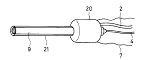
図4は本発明の第4実施例に係り、内視鏡9、LGケーブル2及びカメラコード4に、グリップ20とドレープ7を被せた状態を示す外観図である。
【0031】
本実施例は、グリップ20とスリーブ21の形状が異なることを除くと第2実施例と同じである。第2実施例と同様の構成及び作用については、同じ符号を付して説明を省略する。
【0032】
本実施例では、グリップ20にスリーブ21が、接着や超音波溶着、熱溶着、化学溶着等の溶着手段により固着されている。このスリーブ21は内視鏡9の
挿入部を覆っている。また、このスリーブ21の先端部と、照明と観察が可能な透明部材とが、内視鏡9の先端面と当接するように固着されている。
【0033】
以上のように構成された本実施例では、把持のし易さに加えて、内視鏡9、TVカメラ3、及びカメラコード4は全て、滅菌しない状態、又は極簡単に滅菌する程度で繰り返し使用することができる。
【0034】
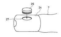
図5乃至図6は本発明の第5実施例に係り、図5はグリップ24の近傍を示す外観図、図6はグリップ24から押しボタン26を外した状態を示す外観図である。
【0035】
本実施例は、グリップ24にボタン26が追加となったことを除くと第2実施例と同じである。第2実施例と同様の構成及び作用については、同じ符号を付して説明を省略する。
【0036】
TVカメラ3にはビデオ録画用等のスイッチ25が設置されており、このスイッチ25と相対した位置のグリップ24上に、弾性部材で構成されたプッシュ式のボタン26が設けられている。ボタン26は、図6に示すように円周方向にU字状の溝を有しており、この溝が、グリップ24に設けられた開口穴27と係合することにより、ボタン26がグリップ24に着脱自在に取り付けられている。
【0037】
以上のように構成された本実施例では、ボタン26を押すと、相対したTVカメラ3のスイッチ25がボタン26の弾性変形により押され、録画状態になる。ボタン26から手を離すと、ボタン26の弾性力により元の形状に復帰するため、スイッチ25は切れて録画待機状態となる。
【0038】
なお、スイッチ25、ボタン26はビデオの録画用のためだけではなく、送水・吸引用のスイッチや撮像状態を変更するスイッチ等、どのようなスイッチを用いても、また1つ又は複数個で構成してもよい。
【0039】
また、グリップ24とボタン26の固定は、本実施例のような係合式ではなく、接着や溶着等でもよい。
【0040】
図7乃至図13は本発明の第6実施例に係り、図7は内視鏡にシースとグリップを取り付けた状態を示す断面図、図8は内視鏡とシースの挿入部の先端部を示す断面図、図9はスペーサの形状を示す平面図、図10は第2のスペーサの形状を示す平面図、図11は第3のスペーサの形状を示す平面図、図12は第4のスペーサの形状を示す平面図、図13は第5のスペーサの形状を示す平面図である。
【0041】
本実施例は、シース及び吸水管が追加となったことを除くと第4実施例と同じである。第4実施例と同様の構成及び作用については、同じ符号を付して説明を省略する。
【0042】
図7に示すように、本実施例のグリップ30は、その先端側に洗浄シース31を着脱自在にネジ込み取り付けできるように構成されている。洗浄シース31には、手元側に図示しない給水源から送水するための送水管32を接続する接続口31aが設けられている。更に、洗浄シース31の内側で、接続口31aより手元側の太径部に、パッキン17が着脱自在に収納され、内視鏡9の先端部側と接続部5との間を水密に保っている。
【0043】
内視鏡9とTVカメラ3は接続された後、グリップ30と固定ツマミ8により固定され、洗浄シース31の挿入部内は、内視鏡9の外径と洗浄シース31の内径の間に送水用の空間36が設けられている。
【0044】
図8に示すように、洗浄シース31の先端部は、内側に折り曲げた円周状の縁34が設けられている。内視鏡9の挿入部先端面と、この縁34との間には弾性部材で形成されたスペーサ35が装着され、内視鏡9の挿入部先端面と縁34の間を水密に保持している。
【0045】
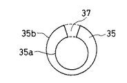
図9に示すように、スペーサ35は、外周35bが洗浄シース31の内径とほぼ同径か、または僅かに小さい径で構成され、内穴35aは内視鏡9の照明部と観察部等を覆うカバーガラス38に対応した部分に設けられ、この内穴35aと外周35bとの間には切欠部37が設けてある。
【0046】
以上のように構成された本実施例での作用は、挿入部手元側を内視鏡9の外径部と洗浄シース31の内径部の間をパッキン17で水密に保持し、先端部を内視鏡9の挿入部の先端面と洗浄シース31の縁34の間をスペーサ35で水密に保持しているため、図示しない送水源より送水管32及び接続口31aを通して生理食塩水などの清浄な液体を空間36内に流すと、空間36内の唯一の開口部となる切欠部37から流れ出す。
【0047】
従って、切欠部37から流れ出した清浄な液体は、カバーガラス38の表面を流れるため、カバーガラス38の表面の汚れ、くもり等を洗い流す。
【0048】
以上のように構成された本実施例では、パッキン17やスペーサ35を介して取り付けるために、内視鏡9、TVカメラ3及び接続部5を確実に固定できるだけではなく、水密状態を維持できる。従って、不潔域であるTVカメラ3、カメラコード4及び接続部5等に付着しているゴミ等が清潔域に落ちるのを防ぐ。
更に、内視鏡9先端部のカバーガラス38の表面が汚れたり、くもったりした場合でも容易に洗浄することができる。
【0049】
なお、切欠部37の幅を変えることにより、カバーガラス38の洗浄力を調整することができる。すなわち、切欠部37の幅を狭く設定すれば、流水の勢いは強くなるため、より洗浄力は強くなり、幅を広く設定すればより広い範囲の洗浄ができる。
【0050】
また、本実施例では、スペーサ35の形状が切欠部37を有する場合について説明したが、洗浄水をカバーガラス38に向かって流すことができれば、他の形状であってもよい。
【0051】
すなわち、図10に示すように、スペーサ35の片面に放射線状の少なくとも1つの溝40を設けたり、図11に示すように、スペーサ35の片面に格子状の溝41を設けて、この溝40、41のある面を各々内視鏡9の先端面側に当接させてもよい。
【0052】
このように構成すると、液体はこの溝に沿って流れるので、泡の発生や乱れがなく、空間36から内視鏡9のカバーガラス38に向かってスムーズに吹き付けられ、カバーガラス38の表面に付着した広範囲の汚れを洗い流すことができる。
【0053】
また、図12に示すように、スペーサ35の切欠部37に加えて、外周35bの周面の厚さ方向に少なくとも1つの溝42を設けたり、図13に示すように、厚さ方向に少なくとも1つの貫通した穴43を設けてもよい。
【0054】
このように構成すると、切欠部37から流れる液体に加えて、この溝42、または穴43を通して僅かに流れる液体が、内視鏡9のカバーガラス38に向かって吹き付けられるため、カバーガラス38の表面全体を洗い流すことができる。
【0055】
以上説明した各実施例において、グリップ部の形状が円筒形状の場合について説明したが、グリップの形状は、術者が把持しやすく、疲労の少ない形状になっていればどの様な形状をしていてもよい。例えば、図14(a)、(b)に示したようなグリップ形状でもよい。
【0056】
図14(a)に示したグリップ46は、術者が把持し易いように指に沿った凹部47が設けられている。また、図14(b)に示したグリップ48は、術者が把持したときに滑り落ちることがないように、フランジ部49が設けられている。
【0057】
ところで、以上説明した各実施例において、内視鏡は、可撓性の内視鏡であっても、可撓性のない硬性鏡であってもよい。次に、その硬性鏡の場合の光学系の構成について説明する。
【0058】
従来の光学系を構成しているレンズの組立は、EP0370191やEP0587177に開示されているように、外套間にレンズ、間隔管、レンズ、間隔管と交互に組み込むことで行っており、組立に要する時間が多く掛かり、製造コストが安くならない原因となっていた。
近年、レンズの素材として、光学ガラスだけでなく、合成樹脂を使用して製造コストを低減させているが、更に製造コストの低減が要望されている。
【0059】
図15は、合成樹脂製のレンズ51と間隔管52とを交互に装着する状態を示す断面図、図16は、レンズ51と間隔管52とを交互に装着して光学系の一部を構成した部組53を外套管54に装着する状態を示す断面図である。
【0060】
図15に示すように、合成樹脂製のレンズ51には、間隔管52の内径52aと嵌合する嵌合部51aと、間隔管52の端面52bと当接する当接部51bとが設けてある。
【0061】
レンズ51と間隔管52の組立は、まず間隔管52をレンズ51の両側より挿入し、順次レンズ51、間隔管52を組み込んで、図16に示す光学系の部組53を構成する。次に、部組53を外套管54の内部に組み込むことにより、光学系のユニットが完成する。
【0062】
以上のように構成することにより、レンズ51と間隔管52は互いに、嵌合部と当接面を有しているので、特別な注意を払うことなく機械的に組み立てを行っても、各レンズ51の光軸と間隔の位置精度を確保できるため、組立工数を短縮することができ、製造コストを低減することができる。
【0063】
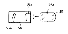
なお、レンズの間隔決めをしている当接面は、レンズ間隔が確保できれば他の形状であってもよい。即ち、図17に示すように、間隔管56の片側には少なくとも1つのカム溝56aを形成し、レンズ57の外周には、カム溝56aに相対した位置に突起57aを設けてもよい。組み立ての際は、この突起57aをカム溝56aに合わせて、レンズ57を間隔管56に嵌合挿入した後、カム溝56aに沿ってレンズ57を回転させて、突起57aを所定の位置に固定させるようにすれば、レンズ57と間隔管56は、各レンズ57の光軸と、間隔の位置精度を確保できるため、組立工数を短縮することができ、製造コストを低減することができる。
【0064】
また、図18に示すように、間隔管58にはスナップフィットを形成する少なくとも1つの係止爪58aを形成し、レンズ59の外周には、係止溝59aを設けてもよい。組み立ての際は、レンズ59を間隔管58に嵌合挿入して、互いにスナップフィットを形成する係止爪58aと係止溝59aを係止させて、位置決めと固定をする。このように構成すれば、ワンタッチで組み立て、固定ができるため、更に製造コストの低減ができる。
【0065】
なお、レンズの素材としては、合成樹脂のPMMA、ポリオレフィン樹脂、PS、PC等の透明度の高い樹脂が考えられる。また、ガラスレンズにより構成しても同様の効果が得られる。
【0066】
なお、以上説明した各実施例では、内視鏡にTVカメラを接続する場合について説明したが、本願発明は、CCD等の固体撮像素子を内視鏡の挿入部内に内蔵するタイプの内視鏡にも適用することが可能である。この場合は、内視鏡と信号コードとの接続部にグリップを取り付けるようにすればよい。
【0067】
また、以上説明した各実施例において、本願の主旨を逸脱しない範囲で任意に組み合わせることが可能である。
【0068】
[付記]
以上詳述したように本発明の実施態様によれば、以下のような構成を得ることができる。すなわち、
[付記1] 結像光学系と固体撮像素子を内蔵した内視鏡と、この内視鏡に接続される像信号を伝送する信号コードと、を覆う医療用滅菌カバーにおいて、前記内視鏡と信号コードとの接続部近傍を覆うグリップ部と、このグリップ部の後端部に接続されたスリーブ状のドレープと、を具備したことを特徴とする医療用滅菌カバー。
【0069】
[付記2] 観察光学系を内蔵した内視鏡による内視鏡像を撮像するTVカメラと、このTVカメラに接続されるTVカメラコードと、を覆う医療用滅菌カバーにおいて、前記TVカメラ近傍を覆うグリップ部と、このグリップ部の後端部に接続されたスリーブ状のドレープと、を具備したことを特徴とする医療用滅菌カバー。
【0070】
[付記3] 付記1項または2項に記載の医療用滅菌カバーであって、前記グリップ部は、少なくとも1つの凸部、または凹部を有する。
【0071】
[付記4] 付記1項または2項に記載の医療用滅菌カバーであって、前記グリップ部に、前記内視鏡に固定するための固定手段が具備されている。
【0072】
[付記5] 付記1項または2項に記載の医療用滅菌カバーであって、前記グリップ部に、前記内視鏡の挿入部側と接続部側との間にシール部材が具備されている。
【0073】
[付記6] 付記5に記載の医療用滅菌カバーであって、前記シール部材は固定部材も兼ねている。
【0074】
[付記7] 付記1項または2項に記載の医療用滅菌カバーであって、前記グリップ部の先端部側に前記内視鏡の挿入部を覆うスリーブが設けられている。
【0075】
[付記8] 付記1項または2項に記載の医療用滅菌カバーであって、前記内視鏡上のスイッチを、前記グリップ部の外から操作可能な少なくとも1つのスイッチ状の弾性部材がが設けられている。
【0076】
[付記9] 間隔管によりレンズ間隔を設定する光学系を有する内視鏡において、レンズ自身に位置決め部位を設けたことを特徴とする内視鏡。
【0077】
[付記10]9項記載の内視鏡であって、前記位置決め部位は、前記レンズ外周に設けたリング状の太径部である。
【0078】
[付記11]間隔管によりレンズ間隔を設定する光学系を有する内視鏡において、レンズと間隔管とで位置決め機構を構成したことを特徴とする内視鏡。
【0079】
[付記12]11項記載の内視鏡であって、前記位置決め機構は、前記レンズの外周に設けた少なくとも1つの突起部と、前記間隔管に設けた前記突起部と係合する細溝と、で構成されている。
【0080】
[付記13]11項記載の内視鏡であって、前記位置決め機構は、前記レンズ外周の周方向の係止用溝と、前記間隔管の端面部に係止用の爪と、を設けた。
【0081】
[付記14]13項記載の内視鏡であって、前記係止用溝は、V溝、またはU溝である。
【0082】
【発明の効果】
以上説明したように、本発明の医療用滅菌カバーによれば、内視鏡の観察を行う場合に、TVカメラ及び接続部の凹凸の多い部分を把持しやすいグリップ部が覆い、内視鏡観察時に術者が内視鏡を把持し易く、且つ体内に挿入してもTVカメラやコードが汚れる虞はないので、覆われるTVカメラやコードは滅菌することなく繰り返し使用することができる。
【図面の簡単な説明】
【図1】図1は本発明の第1実施例を示す斜視図である。
【図2】図2は本発明の第2実施例を示す外観図である。
【図3】図3は本発明の第3実施例を示す断面図である。
【図4】図4は本発明の第4実施例を示す外観図である。
【図5】図5乃至図6は本発明の第5実施例に係り、図5はグリップ部近傍を示す外観図である。
【図6】図6はグリップ24から押しボタン26を外した状態を示す外観図である。
【図7】図7乃至図13は本発明の第6実施例に係り、図7は内視鏡にシースとグリップを取り付けた状態を示す断面図である。
【図8】図8は内視鏡とシースの挿入部の先端部を示す断面図である。
【図9】図9はスペーサの形状を示す平面図である。
【図10】図10は第2のスペーサの形状を示す平面図である。
【図11】図11は第3のスペーサの形状を示す平面図である。
【図12】図12は第4のスペーサの形状を示す平面図である。
【図13】図13は第5のスペーサの形状を示す平面図である。
【図14】図14(a)は、凹部47を設けた本願発明のグリップの外観図、図14(b)は、フランジ部を有する本願発明のグリップの外観図である。
【図15】図15は、合成樹脂製のレンズ51と間隔管52とを交互に装着する状態を示す断面図である。
【図16】図16は、レンズ51と間隔管52とを交互に装着して光学系の一部を構成した部組53を外套管54に装着する状態を示す断面図である。
【図17】図17は、間隔管56とレンズ57との取り付け機構である、カム溝56aと突起57aを示す外観図である。
【図18】図18は、間隔管56とレンズ57との取り付け機構である、スナップフィットを示す断面図である。
【符号の説明】
1、9、14 内視鏡
3 TVカメラ
4 カメラコード
5 接続部
6、10、15、20、24、30、46、48 グリップ
7 ドレープ
21 スリーブ
25 スイッチ
26 ボタン[0001]
[Industrial applications]
The present invention relates to a medical sterilization cover for covering a non-sterile medical device such as a TV camera with a sterilized cover.
[0002]
[Prior art]
Medical equipment for treatment and observation that is difficult to sterilize by washing and disinfection, such as a TV camera adapter and a TV camera cord connected to the rear end of the endoscope or a light guide cable (hereinafter referred to as an LG cable). The applicant of the present invention has proposed a technology that enables use without being sterilized by covering with a cover that has been sterilized in advance, that is, a sterile cover, and that prevents contamination by dirt and the like.
[0003]
In Japanese Patent Application No. 6-2595, a fixing tool is fixed to a rear end of an endoscope insertion portion, and a TV camera or a camera cord is covered with a sheet fixed to the fixing tool, thereby forming a sterile cover.
[0004]
Japanese Patent Application No. 5-245390 discloses a rigid sheath body for connecting a sheath portion for covering an insertion portion of a rigid endoscope and a camera cord cover for covering a TV camera and a camera cord. It is configured to cover.
[0005]
Further, in the following publication, US Pat. No. 4,522,196 discloses a technique in which a TV camera is completely covered with a transparent flexible bag-like case, and a scope is attached from above.
[0006]
U.S. Pat. No. 4,878,485 discloses a technique in which a cover for an LG cable is attached to one side opening of a cover for covering a TV camera body and a camera cable, and an insertion portion of an insertion portion is fixed with an adhesive sheet.
[0007]
[Problems to be solved by the invention]
Since the cover of the invention described in the technical document described above is designed to cover the camera cable from the camera adapter with a thin sheet, first insert the tip of the scope into the camera cover, and then from the rear end side of the scope insertion portion. The camera adapter and cable are attached so as to cover them.
[0008]
In general, in a usage state in which a TV camera adapter and a TV camera cord or an LG cable are connected to a scope, when grasping so that the balance is good and the operability is good, the surgeon takes care of the connection portion and the vicinity of the camera adapter. Often have. However, this camera adapter has a projection, and if the camera adapter is strongly gripped from above a cover made of a soft material such as a polyethylene film, the camera adapter may be caught by the projection and may be broken.
As described above, when the camera adapter is used without being cleaned without being cleaned, if the cover is broken, there is a problem that a clean area such as the cover surface is easily contaminated.
[0009]
In the case of the invention of Japanese Patent Application No. 5-245390, the sheath body can be gripped to prevent the cover from being torn, but the sheath body is used to connect the sheath portion of the insertion portion to the camera cord cover. Therefore, there is a problem that the shape is not suitable for long-time observation because the shape is not easily gripped.
[0010]
Further, even when the cover is not used, the portion to which the camera adapter, the LG cable, and the like are connected is very difficult to hold, and there is a problem that the user gets tired when holding for a long time.
[0011]
The present invention has been made in view of the above problems, When observing the endoscope, the grip portion that easily grips the TV camera and the uneven portion of the connection portion is covered, so that the endoscope can be easily gripped at the time of endoscopic observation, and the TV can be inserted into the body. There is no risk of the camera or cord becoming dirty, and it can be used repeatedly without sterilizing the TV camera or cord It is intended to provide a sterile cover for medical use.
[0012]
Means and action for solving the problem
The present invention relates to a TV camera for capturing an endoscope image by an endoscope having a built-in observation optical system, Said Cover the TV camera cord connected to the TV camera for In the medical sterilization cover, the TV camera Of a cylindrical shape that forms an internal space for inserting Grip part, Said Connected to the rear end of the grip A drape portion for covering the TV camera cord, and the grip portion and the endoscope in a state where the TV camera is inserted into an internal space of the grip portion and the drape portion covers the TV camera cord. Fixing means provided on the grip portion for detachably fixing Configuration.
[0013]
With such a configuration, the grip portion that easily grips the TV camera body and the uneven portion of the connection portion is covered, and the TV camera cord portion is covered with the sleeve-shaped drape, so that the TV camera cord portion is easily gripped during endoscopic observation. At the same time, since the TV camera and the cord do not become dirty even when inserted into the body, the covered TV camera and the cord can be used repeatedly without sterilization.
[0014]
【Example】
An embodiment of the present invention will be described below with reference to the drawings.
[0015]
FIG. 1 is a perspective view showing a state in which a
[0016]
The endoscope apparatus shown in FIG. 1 captures an endoscope image formed by an endoscope 1, an LG
The
[0017]
In the embodiment configured as described above, since the
[0018]
Further, since the
[0019]
FIG. 2 is an external view showing a state in which a
[0020]
This embodiment is the same as the first embodiment except that the shapes of the
[0021]
The
[0022]
In the present embodiment configured as described above, not only the
[0023]
FIG. 3 is a sectional view showing a state in which a
[0024]
This embodiment is the same as the second embodiment except that the shapes of the grip portion and the
[0025]
A grip portion covering the
[0026]
When attaching the grip portion to the
[0027]
In the present embodiment configured as described above, since the
[0028]
Further, unlike the first and second embodiments, the protrusion such as the fixing
[0029]
Simultaneously fixing the endoscope and the grip portion and performing the waterproof seal as in this embodiment is effective in that the space is not wasted, but the fixed and waterproof seals are different from each other. It may be configured. That is, as a fixing method, a screw such as the fixing
[0030]
FIG. 4 is an external view showing a state in which a
[0031]
This embodiment is the same as the second embodiment except that the shapes of the
[0032]
In this embodiment, the
Covers the insert. The distal end of the
[0033]
In the present embodiment configured as described above, in addition to the ease of grasping, the
[0034]
5 and 6 relate to a fifth embodiment of the present invention. FIG. 5 is an external view showing the vicinity of the
[0035]
This embodiment is the same as the second embodiment except that a
[0036]
The
[0037]
In this embodiment configured as described above, when the
[0038]
The
[0039]
Further, the fixing of the
[0040]
7 to 13 relate to a sixth embodiment of the present invention. FIG. 7 is a cross-sectional view showing a state in which a sheath and a grip are attached to an endoscope. FIG. 9, FIG. 9 is a plan view showing the shape of the second spacer, FIG. 10 is a plan view showing the shape of the second spacer, FIG. 11 is a plan view showing the shape of the third spacer, and FIG. 12 is a fourth spacer. FIG. 13 is a plan view showing the shape of the fifth spacer.
[0041]
This embodiment is the same as the fourth embodiment except that a sheath and a water suction pipe are added. The same components and operations as in the fourth embodiment are denoted by the same reference numerals, and description thereof is omitted.
[0042]
As shown in FIG. 7, the
[0043]
After the
[0044]
As shown in FIG. 8, the distal end of the cleaning
[0045]
As shown in FIG. 9, the
[0046]
The operation of the present embodiment configured as described above is as follows. The proximal side of the insertion portion is held watertight between the outer diameter portion of the
[0047]
Therefore, the clean liquid that has flowed out of the
[0048]
In the present embodiment configured as described above, since the
Further, even if the surface of the
[0049]
The cleaning power of the
[0050]
Further, in the present embodiment, the case where the shape of the
[0051]
That is, as shown in FIG. 10, at least one
[0052]
With this configuration, since the liquid flows along the groove, no bubbles are generated or disturbed, and the liquid is smoothly sprayed from the
[0053]
In addition, as shown in FIG. 12, in addition to the
[0054]
With this configuration, in addition to the liquid flowing from the
[0055]
In each of the embodiments described above, the case where the shape of the grip portion is cylindrical has been described.However, the shape of the grip is any shape as long as it is easy for the operator to grasp and the shape with less fatigue. You may. For example, a grip shape as shown in FIGS. 14A and 14B may be used.
[0056]
The
[0057]
By the way, in each of the embodiments described above, the endoscope may be a flexible endoscope or a rigid endoscope having no flexibility. Next, the configuration of the optical system in the case of the rigid endoscope will be described.
[0058]
As disclosed in EP 0370191 and EP 0587177, assembling of a lens constituting a conventional optical system is performed by alternately incorporating a lens, an interval tube, a lens, and an interval tube between mantles, which is required for assembly. It took a lot of time, and it was a cause that the manufacturing cost was not reduced.
In recent years, not only optical glass but also synthetic resin has been used as a lens material to reduce the manufacturing cost, but there is a demand for further reduction in the manufacturing cost.
[0059]
FIG. 15 is a cross-sectional view showing a state in which a
[0060]
As shown in FIG. 15, the
[0061]
When assembling the
[0062]
With the above-described configuration, the
[0063]
The contact surface for determining the distance between the lenses may have another shape as long as the distance between the lenses can be ensured. That is, as shown in FIG. 17, at least one
[0064]
In addition, as shown in FIG. 18, at least one locking
[0065]
In addition, as a material of the lens, a highly transparent resin such as synthetic resin PMMA, polyolefin resin, PS, or PC can be considered. Further, the same effect can be obtained by using a glass lens.
[0066]
In each of the embodiments described above, the case where the TV camera is connected to the endoscope has been described. However, the present invention relates to an endoscope in which a solid-state imaging device such as a CCD is incorporated in an insertion portion of the endoscope. It is also possible to apply to. In this case, the grip may be attached to the connection between the endoscope and the signal cord.
[0067]
Further, in each of the embodiments described above, it is possible to arbitrarily combine them without departing from the gist of the present application.
[0068]
[Appendix]
As described in detail above, according to the embodiment of the present invention, the following configuration can be obtained. That is,
[Supplementary Note 1] A medical sterilization cover for covering an endoscope having a built-in imaging optical system and a solid-state imaging device and a signal code for transmitting an image signal connected to the endoscope, A medical sterilization cover, comprising: a grip portion that covers a vicinity of a connection portion with a signal cord; and a sleeve-shaped drape connected to a rear end portion of the grip portion.
[0069]
[Supplementary Note 2] A medical sterilization cover that covers a TV camera that captures an endoscope image by an endoscope having a built-in observation optical system and a TV camera code that is connected to the TV camera, covers the vicinity of the TV camera. A medical sterilization cover comprising: a grip portion; and a sleeve-shaped drape connected to a rear end portion of the grip portion.
[0070]
[Supplementary Note 3] The medical sterilization cover according to
[0071]
[Supplementary Note 4] The medical sterilization cover according to
[0072]
[Supplementary Note 5] The medical sterilization cover according to
[0073]
[Supplementary Note 6] The medical sterilization cover according to
[0074]
[Supplementary Note 7] The medical sterilization cover according to
[0075]
[Supplementary Note 8] The medical sterilization cover according to
[0076]
[Supplementary Note 9] An endoscope having an optical system for setting a lens interval by an interval tube, wherein a positioning portion is provided on the lens itself.
[0077]
[Supplementary Note 10] The endoscope according to
[0078]
[Supplementary Note 11] An endoscope having an optical system for setting a lens interval by an interval tube, wherein a positioning mechanism is configured by the lens and the interval tube.
[0079]
[Supplementary Note 12] The endoscope according to item 11, wherein the positioning mechanism includes at least one protrusion provided on an outer periphery of the lens, and a narrow groove provided on the spacing tube and engaging with the protrusion. , Is composed.
[0080]
[Supplementary Note 13] The endoscope according to Item 11, wherein the positioning mechanism includes a locking groove in a circumferential direction on an outer periphery of the lens, and a locking claw on an end surface of the spacing tube. .
[0081]
[Supplementary Note 14] The endoscope according to item 13, wherein the locking groove is a V groove or a U groove.
[0082]
【The invention's effect】
As described above, according to the medical sterilization cover of the present invention, When observing the endoscope, the TV camera and the grip portion that easily grips the uneven portion of the connection portion are covered, so that the surgeon can observe the endoscope. Easy to grasp the endoscope, and Body Since there is no possibility that the TV camera or the cord becomes dirty even if it is inserted into the inside, the TV camera or the cord to be covered can be used repeatedly without sterilization.
[Brief description of the drawings]
FIG. 1 is a perspective view showing a first embodiment of the present invention.
FIG. 2 is an external view showing a second embodiment of the present invention.
FIG. 3 is a sectional view showing a third embodiment of the present invention.
FIG. 4 is an external view showing a fourth embodiment of the present invention.
FIGS. 5 and 6 relate to a fifth embodiment of the present invention, and FIG. 5 is an external view showing the vicinity of a grip portion.
FIG. 6 is an external view showing a state where the
7 to 13 relate to a sixth embodiment of the present invention, and FIG. 7 is a sectional view showing a state in which a sheath and a grip are attached to the endoscope.
FIG. 8 is a cross-sectional view showing a distal end portion of an insertion portion of an endoscope and a sheath.
FIG. 9 is a plan view showing the shape of a spacer.
FIG. 10 is a plan view showing the shape of a second spacer.
FIG. 11 is a plan view showing the shape of a third spacer.
FIG. 12 is a plan view showing a shape of a fourth spacer.
FIG. 13 is a plan view showing a shape of a fifth spacer.
14 (a) is an external view of a grip of the present invention provided with a
FIG. 15 is a cross-sectional view showing a state in which
FIG. 16 is a cross-sectional view showing a state in which a
FIG. 17 is an external view showing a
FIG. 18 is a cross-sectional view showing a snap fit, which is a mechanism for attaching the
[Explanation of symbols]
1,9,14 Endoscope
3 TV camera
4 Camera code
5 Connection
6, 10, 15, 20, 24, 30, 46, 48 grip
7 Drape
21 sleeve
25 switch
26 button
Claims (1)
前記TVカメラを挿入するための内部空間を形成する円筒形状のグリップ部と、
前記グリップ部の後端部に接続され、前記TVカメラコードを覆うためのドレープ部と、
前記グリップ部の内部空間内に前記TVカメラが挿入され、且つ前記ドレープ部が前記TVカメラコードを覆った状態で前記グリップ部と前記内視鏡とを着脱自在に固定する前記グリップ部に設けられた固定手段と、
を有することを特徴とする医療用滅菌カバー。A TV camera for imaging the endoscope image by the endoscope with a built-observation optical system, a TV camera cord connected to the TV camera, in the medical sterilization cover for covering,
A cylindrical grip portion forming an internal space for inserting the TV camera,
Is connected to the rear end of the grip portion, the drape portion for covering the TV camera code,
The TV camera is inserted into the internal space of the grip unit, and the drape unit is provided on the grip unit for detachably fixing the grip unit and the endoscope while covering the TV camera cord. Fixing means,
Medical sterilization cover and having a.
Priority Applications (1)
| Application Number | Priority Date | Filing Date | Title |
|---|---|---|---|
| JP02009595A JP3576239B2 (en) | 1995-02-08 | 1995-02-08 | Medical sterilization cover |
Applications Claiming Priority (1)
| Application Number | Priority Date | Filing Date | Title |
|---|---|---|---|
| JP02009595A JP3576239B2 (en) | 1995-02-08 | 1995-02-08 | Medical sterilization cover |
Publications (2)
| Publication Number | Publication Date |
|---|---|
| JPH08206056A JPH08206056A (en) | 1996-08-13 |
| JP3576239B2 true JP3576239B2 (en) | 2004-10-13 |
Family
ID=12017563
Family Applications (1)
| Application Number | Title | Priority Date | Filing Date |
|---|---|---|---|
| JP02009595A Expired - Fee Related JP3576239B2 (en) | 1995-02-08 | 1995-02-08 | Medical sterilization cover |
Country Status (1)
| Country | Link |
|---|---|
| JP (1) | JP3576239B2 (en) |
Cited By (1)
| Publication number | Priority date | Publication date | Assignee | Title |
|---|---|---|---|---|
| KR20190113051A (en) * | 2018-03-27 | 2019-10-08 | (주)아시아덴탈 | Dental hose cover device |
Families Citing this family (4)
| Publication number | Priority date | Publication date | Assignee | Title |
|---|---|---|---|---|
| US6863651B2 (en) * | 2001-10-19 | 2005-03-08 | Visionscope, Llc | Miniature endoscope with imaging fiber system |
| JP4165101B2 (en) * | 2002-03-28 | 2008-10-15 | フジノン株式会社 | Covered endoscope |
| JP2004113688A (en) * | 2002-09-30 | 2004-04-15 | Pentax Corp | Overcoat sheath pack of endoscope |
| US11701195B2 (en) | 2015-10-14 | 2023-07-18 | Dexerials Corporation | Optical film, connecting member, endoscope camera drape, endoscope device, medical system, optical film production method, and connecting member production method |
-
1995
- 1995-02-08 JP JP02009595A patent/JP3576239B2/en not_active Expired - Fee Related
Cited By (2)
| Publication number | Priority date | Publication date | Assignee | Title |
|---|---|---|---|---|
| KR20190113051A (en) * | 2018-03-27 | 2019-10-08 | (주)아시아덴탈 | Dental hose cover device |
| KR102054456B1 (en) | 2018-03-27 | 2019-12-10 | (주)아시아덴탈 | Dental hose cover device |
Also Published As
| Publication number | Publication date |
|---|---|
| JPH08206056A (en) | 1996-08-13 |
Similar Documents
| Publication | Publication Date | Title |
|---|---|---|
| US5575756A (en) | Endoscope apparatus | |
| AU662006B2 (en) | Sheath for protecting endoscope from contamination | |
| US5447148A (en) | Endoscopic contamination protection system to facilitate cleaning of endoscopes | |
| JPH06315458A (en) | Endoscope | |
| JP2000171730A (en) | Battery type portable endoscopic device | |
| CN111065313A (en) | Endoscope with a detachable handle | |
| JP3576239B2 (en) | Medical sterilization cover | |
| JP2971608B2 (en) | Endoscope cleaning and disinfecting equipment | |
| JP2019536547A (en) | Endoscope and method of using camera assembly in endoscope | |
| JP2003250748A (en) | Cover for endoscope | |
| JP7440659B2 (en) | Endoscope with working channel and control body | |
| JP3075295B2 (en) | Endoscope | |
| JP2003102670A (en) | Endoscope cover | |
| JP2008167772A (en) | Medical instrument with housing cover and medical system using the same | |
| JP3514840B2 (en) | Cover type endoscope and mounting method of endoscope cover | |
| JP2599952Y2 (en) | Endoscope with endoscope cover method | |
| JPH0666606U (en) | Endoscope with channel cover system | |
| JPH10127577A (en) | Endoscope | |
| JP2003102678A (en) | Mouthpiece for endoscope | |
| JPH0663002U (en) | Endoscope cover type endoscope device | |
| JP3371385B2 (en) | Cover-type endoscope | |
| JPH0675401U (en) | Endoscope cover type endoscope device | |
| JPH0661203U (en) | Endoscope cover type endoscope device | |
| JPH0663001U (en) | Endoscope cover type endoscope device | |
| JPH0668708U (en) | Endoscope cover type endoscope device |
Legal Events
| Date | Code | Title | Description |
|---|---|---|---|
| TRDD | Decision of grant or rejection written | ||
| A01 | Written decision to grant a patent or to grant a registration (utility model) |
Free format text: JAPANESE INTERMEDIATE CODE: A01 Effective date: 20040629 |
|
| A61 | First payment of annual fees (during grant procedure) |
Free format text: JAPANESE INTERMEDIATE CODE: A61 Effective date: 20040707 |
|
| FPAY | Renewal fee payment (event date is renewal date of database) |
Free format text: PAYMENT UNTIL: 20080716 Year of fee payment: 4 |
|
| FPAY | Renewal fee payment (event date is renewal date of database) |
Free format text: PAYMENT UNTIL: 20090716 Year of fee payment: 5 |
|
| FPAY | Renewal fee payment (event date is renewal date of database) |
Free format text: PAYMENT UNTIL: 20100716 Year of fee payment: 6 |
|
| FPAY | Renewal fee payment (event date is renewal date of database) |
Free format text: PAYMENT UNTIL: 20100716 Year of fee payment: 6 |
|
| FPAY | Renewal fee payment (event date is renewal date of database) |
Free format text: PAYMENT UNTIL: 20110716 Year of fee payment: 7 |
|
| FPAY | Renewal fee payment (event date is renewal date of database) |
Free format text: PAYMENT UNTIL: 20120716 Year of fee payment: 8 |
|
| LAPS | Cancellation because of no payment of annual fees |