JP3574916B2 - Battery adapter - Google Patents
Battery adapter Download PDFInfo
- Publication number
- JP3574916B2 JP3574916B2 JP12837798A JP12837798A JP3574916B2 JP 3574916 B2 JP3574916 B2 JP 3574916B2 JP 12837798 A JP12837798 A JP 12837798A JP 12837798 A JP12837798 A JP 12837798A JP 3574916 B2 JP3574916 B2 JP 3574916B2
- Authority
- JP
- Japan
- Prior art keywords
- terminal
- battery
- post member
- post
- outer diameter
- Prior art date
- Legal status (The legal status is an assumption and is not a legal conclusion. Google has not performed a legal analysis and makes no representation as to the accuracy of the status listed.)
- Expired - Lifetime
Links
- 239000002184 metal Substances 0.000 claims description 6
- 229910052751 metal Inorganic materials 0.000 claims description 6
- 239000004020 conductor Substances 0.000 claims description 3
- 230000002093 peripheral effect Effects 0.000 claims description 2
- XEEYBQQBJWHFJM-UHFFFAOYSA-N Iron Chemical compound [Fe] XEEYBQQBJWHFJM-UHFFFAOYSA-N 0.000 description 6
- 238000002788 crimping Methods 0.000 description 4
- 229910052742 iron Inorganic materials 0.000 description 3
- 239000007779 soft material Substances 0.000 description 2
- 230000000694 effects Effects 0.000 description 1
Images


Classifications
-
- Y—GENERAL TAGGING OF NEW TECHNOLOGICAL DEVELOPMENTS; GENERAL TAGGING OF CROSS-SECTIONAL TECHNOLOGIES SPANNING OVER SEVERAL SECTIONS OF THE IPC; TECHNICAL SUBJECTS COVERED BY FORMER USPC CROSS-REFERENCE ART COLLECTIONS [XRACs] AND DIGESTS
- Y02—TECHNOLOGIES OR APPLICATIONS FOR MITIGATION OR ADAPTATION AGAINST CLIMATE CHANGE
- Y02E—REDUCTION OF GREENHOUSE GAS [GHG] EMISSIONS, RELATED TO ENERGY GENERATION, TRANSMISSION OR DISTRIBUTION
- Y02E60/00—Enabling technologies; Technologies with a potential or indirect contribution to GHG emissions mitigation
- Y02E60/10—Energy storage using batteries
Landscapes
- Connection Of Batteries Or Terminals (AREA)
Description
【発明の属する技術分野】
【0001】
本発明はバッテリアダプターに係り、特に、バッテリの電極ポストの外径とバッテリケーブル先端のターミナルの内径が一致しない場合、それら電極ポストとターミナルとを接続するのに用いられるバッテリアダプターに関する。
【従来の技術】
【0002】
自動車等に用いられるバッテリには、図8のように外径の小さい電極ポスト1を有するものと、図9のように外径の大きい電極ポスト2を有するものの2種類がある。一方、バッテリケーブル3先端のターミナルも、内径の小さいターミナル4と、内径の大きいターミナル5の2種類が用意されている。
【0003】
ところで、近年、始動性向上のために、外径の大きい電極ポストを有するバッテリが多く使用されるようになっている。従来の自動車の多くには、外径の小さい電極ポストを有するバッテリが載せられており、このような自動車に外径の大きい電極ポストを有するバッテリを載せるには、バッテリケーブル先端のターミナルも内径の大きいものに切り替えなければならない。通常、バッテリケーブルとターミナルは圧着により一体化されており、ターミナルを内径の小さいものから大きいものに切り替えるために、従来では、バッテリケーブル全体を付け替えてしまうか、又は圧着されていたターミナルをバッテリケーブルから切り離し、内径の大きいターミナルを圧着し直すことが行われていた。
【発明が解決しようとする課題】
【0004】
しかしながら、上記従来のように、バッテリケーブル全体を付け替えたり、内径の大きいターミナルを圧着し直したりしていると、その作業が煩雑であるとともに、作業に時間が掛かってコスト高となる欠点がある。
【0005】
本発明の目的は、バッテリケーブルを付け替えたり、ターミナルを圧着し直したりすることなく、互いにサイズの異なる電極ポストとターミナルとを容易に接続することのできるバッテリアダプターを提供することにある。
【課題を解決するための手段】
【0006】
上記目的を達成するために、本発明は、バッテリの電極ポストに固定される固定部、バッテリケーブル先端のターミナルが装着されるポスト部材とを備え、前記固定部及び前記ポスト部材を含めて全体が導電材で形成され、前記ポスト部材は、硬い金属で円錐台形状に形成されており、下部に工具を嵌合するための締付工具嵌合部が形成され、バッテリアダプター本体に設けられたスタッドボルトに、該スタッドボルトの雄ねじに螺合可能な雌ねじによって着脱自在に取り付けられて外径の異なるポスト部材と交換可能であり、先端周縁に、該ポスト部材に装着された前記ターミナルを係止するために鍔状に径が大きくなった鍔部を設けたことを特徴としている。
【0007】
上記構成によれば、ターミナルの内径が電極ポストの外径に一致していなくとも、ターミナルの内径に外径が一致したポスト部材を選択して使用することにより、バッテリアダプターを介して電極ポストとターミナルとを容易に接続することができる。
【0008】
さらに、円錐台形状に形成されたポスト部材の先端周縁に鍔部を設けておけば、ターミナルが鍔部によって係止されるので、ターミナルをポスト部材に密着させることができる。また、振動等によってターミナルがポスト部材から抜けてしまうのを防止することもできる。このとき、通常、バッテリの電極ポストは鉛等の柔らかい材料で形成され、ターミナルで挟持して締め付けたときに、電極ポストとターミナルとが密着するようになってい る。しかし、鍔部を設けておけば、ターミナルをポスト部材に密着させることができるので、ポスト部材を鉛等の柔らかい材料にする必要がなく、硬い金属で形成することができる。
【発明の実施の形態】
【0009】
以下、本発明の実施の形態を図面に従って説明する。
【0010】
(実施の形態1)
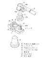
図1は、本発明の実施の形態1によるバッテリアダプターを用いて、バッテリケーブルをバッテリの電極ポストに接続する様子を示した分解斜視図である。図1に示すように、バッテリアダプター本体10は固定部11とスタッドボルト12を有する。固定部11には円形穴13が設けられ、この円形穴13に、外径の大きい電極ポスト2が挿通される。円形穴13は1カ所に切り込み14が形成されており、固定部11は切り込み14より先端側が2つに分割されている。そして固定部11には、図示してないが2つに分割されたそれぞれの部分に穴が形成され、それらの穴にねじ15が挿通され、そのねじ15にはナット16が螺合されている。
【0011】
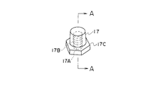
スタッドボルト12は固定部11の一部に固定され、このスタッドボルト12にはほぼ円錐台形状のポスト部材17が取り付けられる。ポスト部材17は電極ポスト2と同様に鉛で形成され、またポスト部材17の外径は電極ポスト2の外径よりも小さくなっている。ポスト部材17には、図2及び図3に示すように、その中心軸に沿って穴17Aが形成されている。穴17A内面には雌ねじ17Bが刻まれており、この雌ねじ17Bはスタッドボルト12外面の雄ねじ12Aに螺合可能となっている。また、ポスト部材17の下部には六角形をなした締付工具嵌合部17Cが形成され、ポスト部材17の穴17Aをスタッドボルト12に合わせて、締付工具嵌合部17Cをレンチ等を用いて回転させることにより、ポスト部材17の雌ねじ17Bとスタッドボルト12の雄ねじ12Aとが螺合して、ポスト部材17をスタッドボルト12に容易に取り付けることができる。なお、固定部11及びスタッドボルト12は鉄等の導電材で形成されている。
【0012】
バッテリケーブル3は従来のものと同じ構成であり、その先端には内径の小さいターミナル4が圧着により取り付けられている。また、ターミナル4には、ねじ4Aと、ねじ4Aに螺合したナット4Bが設けられいる。
【0013】
上記構成のバッテリアダプターによれば、外径の大きい電極ポスト2に、内径の小さいターミナル4を有するバッテリケーブル3を接続する場合、予めターミナル4の内径に合致した外径を有するポスト部材17をスタッドボルト12に取り付けておく。そして、固定部11先端のナット16を緩め、電極ポスト2が穴11に十分に挿通された状態となるまでバッテリアダプター本体10をバッテリ側(図1では下側)に押し込んでから、ナット16を締め付ける。これによって、バッテリアダプター本体10が電極ポスト2に強固に固定される。
【0014】
次に、ターミナル4のナット4Bを緩めて、ターミナル4にポスト部材17を嵌合させてから、ナット4Bを締め付ける。これによって、バッテリケーブル3がバッテリアダプター本体10に強固に固定される。
【0015】
本実施の形態によれば、バッテリアダプターを介して、外径の大きい電極ポスト2に、内径の小さいターミナル4を有するバッテリケーブル3を容易に接続することが可能となる。
【0016】
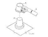
(実施の形態2)
図4は、本発明の実施の形態2によるバッテリアダプターを用いて、バッテリケーブルをバッテリの電極ポストに接続する様子を示した分解斜視図である。また図5は、上記バッテリアダプターを用いて、バッテリケーブルをバッテリの電極ポストに接続した様子を示した斜視図である。本実施の形態はポスト部材20に特徴がある。すなわち、円錐台形状をなしたポスト部材20は上端部に鍔部20Cが設けられ、かつ全体が鉄等の硬い金属で形成されている。なお、ポスト部材20には、図6及び図7に示すように、その中心軸に沿って穴20Aが形成され、穴20A内面に刻まれた雌ねじ20Bはスタッドボルト12外面の雄ねじ12Aに螺合可能となっている。
【0017】
実施の形態1ではポスト部材は鉛で形成され、ターミナルで挟持して締め付けたときに、ターミナルがポスト部材に食い込むことにより、ターミナルとポストとの密着性が確保されるようになっていた。しかし、ポスト部材を鉛等の柔らかい金属で形成すると、クリープ等によってポスト部材とスタッドボルトとの間に緩みが生じる恐れがある。
【0018】
本実施の形態では、ポスト部材20の上端部に鍔部20Cを設けることによって、ターミナル4をバッテリアダプター本体10側に押しつけ、ターミナル4とポスト部材20との密着性を確保している。このため本実施の形態によれば、ポスト部材20を鉄等の硬い金属で形成することが可能となり、クリープ等によってポスト部材20とスタッドボルト12との間に緩みが生じる恐れはない。
【0019】
なお、実施の形態1・2では、外径の大きい電極ポスト2に内径の小さいターミナル4を有するバッテリケーブル3を接続する場合について説明してきたが、本発明のバッテリアダプターは、外径の小さい電極ポスト1に内径の小さいターミナル5を有するバッテリケーブル3を接続する場合にも適用できる。また、ポスト部材17または20はスタッドボルト12にねじによって取り付けられているので、外径が任意の大きさのポスト部材に取り替えることが可能である。
【発明の効果】
【0020】
以上説明したように、本発明によれば、ターミナルの内径が電極ポストの外径に一致していなくとも、ターミナルの内径に外径が一致したポスト部材を選択して使用することにより、電極ポストとターミナルとを容易に接続することができる。その結果、バッテリケーブルを全て付け替えたり、ターミナルを圧着し直したりする必要がなくなり、作業の簡素化とコスト低減を図ることができる。
【図面の簡単な説明】
【図1】本発明の実施の形態1によるバッテリアダプターを用いて、バッテリケーブルをバッテリの電極ポストに接続する様子を示した分解斜視図である。
【図2】図1におけるポスト部材の斜視図である。
【図3】図2のA−A線に沿った断面図である。
【図4】本発明の実施の形態2によるバッテリアダプターを用いて、バッテリケーブルをバッテリの電極ポストに接続する様子を示した分解斜視図である。
【図5】図4のバッテリアダプターを用いて、バッテリケーブルをバッテリの電極ポストに接続した様子を示した斜視図である。
【図6】図4におけるポスト部材の斜視図である。
【図7】図6のB−B線に沿った断面図である。
【図8】外径の小さい電極ポストに内径の小さいターミナルを接続する様子を示した斜視図である。
【図9】外径の大きい電極ポストに内径の大きいターミナルを接続する様子を示した斜視図である。
【符号の説明】
1 外径の小さい電極ポスト
2 外径の大きい電極ポスト
3 バッテリケーブル
4 内径の小さいターミナル
5 内径の大きいターミナル
10 バッテリアダプター本体
11 固定部
12 スタッドボルト
17 ポスト部材
17C 締付工具嵌合部
20 ポスト部材
20C 鍔部TECHNICAL FIELD OF THE INVENTION
[0001]
The present invention relates to a battery adapter, and more particularly to a battery adapter used to connect an electrode post of a battery and a terminal of the battery cable when the outer diameter of the terminal does not match the inner diameter of the terminal of the battery cable.
[Prior art]
[0002]
There are two types of batteries used for automobiles and the like, one having an electrode post 1 having a small outer diameter as shown in FIG. 8 and one having an
[0003]
By the way, in recent years, batteries having electrode posts having a large outer diameter have been often used to improve startability. Many conventional automobiles carry a battery having an electrode post with a small outer diameter, and in order to mount a battery with an electrode post with a large outer diameter on such an automobile, the terminal at the end of the battery cable must also have an inner diameter. You have to switch to a big one. Usually, the battery cable and the terminal are integrated by crimping, and in order to switch the terminal from a small inner diameter to a larger one, conventionally, the entire battery cable is replaced or the crimped terminal is replaced with the battery cable. From the terminal, and re-crimping the terminal with a large inner diameter.
[Problems to be solved by the invention]
[0004]
However, when the entire battery cable is replaced or the terminal having a large inner diameter is crimped again as in the above-described conventional case, the operation is complicated, and the operation is time-consuming and costly. .
[0005]
An object of the present invention is to provide a battery adapter that can easily connect electrode posts and terminals having different sizes to each other without replacing a battery cable or re-crimping a terminal.
[Means for Solving the Problems]
[0006]
In order to achieve the above object, the present invention includes a fixing portion fixed to an electrode post of a battery, and a post member to which a terminal at the tip of a battery cable is attached, and the entirety including the fixing portion and the post member is provided. The post member is formed of a conductive material, the post member is formed of a hard metal in a truncated cone shape, a fastening tool fitting portion for fitting a tool is formed at a lower portion, and a stud provided on a battery adapter body. the bolt, the stud bolt of the external thread is attached detachably by threadable internal thread Ri replaceable der different post member having an outer diameter, the tip perimeter, locks the terminal mounted on said post member In order to achieve this, a flange portion having a larger diameter is provided in a flange shape .
[0007]
According to the above configuration, even if the inner diameter of the terminal does not match the outer diameter of the electrode post, by selecting and using a post member whose outer diameter matches the inner diameter of the terminal, the electrode post is connected to the electrode post via the battery adapter. The terminal can be easily connected.
[0008]
Further, if a flange is provided on the peripheral edge of the post member formed in the shape of a truncated cone , the terminal is locked by the flange, so that the terminal can be brought into close contact with the post member. Further, it is possible to prevent the terminal from coming off the post member due to vibration or the like. At this time, usually, the electrode posts of a battery is formed of a soft material such as lead, when tightened by clamping in the terminal, and the electrode post and the terminals that are adapted to contact. However, if the flange is provided, the terminal can be brought into close contact with the post member, so that the post member does not need to be made of a soft material such as lead, and can be formed of a hard metal.
BEST MODE FOR CARRYING OUT THE INVENTION
[0009]
Hereinafter, embodiments of the present invention will be described with reference to the drawings.
[0010]
(Embodiment 1)
FIG. 1 is an exploded perspective view showing how a battery cable is connected to an electrode post of a battery using the battery adapter according to the first embodiment of the present invention. As shown in FIG. 1, the
[0011]
The stud bolt 12 is fixed to a part of the fixing portion 11, and a substantially frustoconical post member 17 is attached to the stud bolt 12. The post member 17 is formed of lead like the
[0012]
The
[0013]
According to the battery adapter having the above-described configuration, when the
[0014]
Next, the
[0015]
According to the present embodiment, it is possible to easily connect the
[0016]
(Embodiment 2)
FIG. 4 is an exploded perspective view showing how a battery cable is connected to an electrode post of a battery using the battery adapter according to the second embodiment of the present invention. FIG. 5 is a perspective view showing a state in which a battery cable is connected to an electrode post of a battery using the battery adapter. This embodiment is characterized by the
[0017]
In the first embodiment, the post member is formed of lead, and when the terminal member is pinched and tightened, the terminal bites into the post member, thereby ensuring the close contact between the terminal and the post. However, if the post member is formed of a soft metal such as lead, there is a possibility that the post member may be loosened due to creep or the like.
[0018]
In the present embodiment, the
[0019]
In the first and second embodiments, the case where the
【The invention's effect】
[0020]
As described above, according to the present invention, even when the inner diameter of the terminal does not match the outer diameter of the electrode post, the electrode post is selected and used by selecting a post member whose outer diameter matches the inner diameter of the terminal. And the terminal can be easily connected. As a result, it is not necessary to replace all the battery cables or to re-crimp the terminals, so that the operation can be simplified and the cost can be reduced.
[Brief description of the drawings]
FIG. 1 is an exploded perspective view showing how a battery cable is connected to an electrode post of a battery using a battery adapter according to a first embodiment of the present invention.
FIG. 2 is a perspective view of a post member in FIG.
FIG. 3 is a sectional view taken along line AA of FIG. 2;
FIG. 4 is an exploded perspective view showing how a battery cable is connected to an electrode post of a battery using the battery adapter according to the second embodiment of the present invention.
FIG. 5 is a perspective view showing a state where a battery cable is connected to an electrode post of a battery using the battery adapter of FIG. 4;
6 is a perspective view of the post member in FIG.
FIG. 7 is a sectional view taken along the line BB of FIG. 6;
FIG. 8 is a perspective view showing a state in which a terminal having a small inner diameter is connected to an electrode post having a small outer diameter.
FIG. 9 is a perspective view showing a state in which a terminal having a large inner diameter is connected to an electrode post having a large outer diameter.
[Explanation of symbols]
DESCRIPTION OF SYMBOLS 1 Electrode post with a small
Claims (1)
Priority Applications (1)
| Application Number | Priority Date | Filing Date | Title |
|---|---|---|---|
| JP12837798A JP3574916B2 (en) | 1998-05-12 | 1998-05-12 | Battery adapter |
Applications Claiming Priority (1)
| Application Number | Priority Date | Filing Date | Title |
|---|---|---|---|
| JP12837798A JP3574916B2 (en) | 1998-05-12 | 1998-05-12 | Battery adapter |
Publications (2)
| Publication Number | Publication Date |
|---|---|
| JPH11329400A JPH11329400A (en) | 1999-11-30 |
| JP3574916B2 true JP3574916B2 (en) | 2004-10-06 |
Family
ID=14983325
Family Applications (1)
| Application Number | Title | Priority Date | Filing Date |
|---|---|---|---|
| JP12837798A Expired - Lifetime JP3574916B2 (en) | 1998-05-12 | 1998-05-12 | Battery adapter |
Country Status (1)
| Country | Link |
|---|---|
| JP (1) | JP3574916B2 (en) |
Families Citing this family (5)
| Publication number | Priority date | Publication date | Assignee | Title |
|---|---|---|---|---|
| EP1162692B1 (en) | 2000-06-05 | 2008-03-05 | Yazaki Corporation | Battery terminal and battery post adaptor |
| WO2003100886A1 (en) | 2002-05-27 | 2003-12-04 | Japan Storage Battery Co., Ltd. | Battery |
| JP2009105075A (en) * | 2009-02-16 | 2009-05-14 | Gs Yuasa Corporation:Kk | Battery |
| JP5256110B2 (en) * | 2009-04-27 | 2013-08-07 | 株式会社京三製作所 | Electrical equipment |
| JP5545400B2 (en) * | 2013-07-22 | 2014-07-09 | 株式会社Gsユアサ | battery |
Family Cites Families (8)
| Publication number | Priority date | Publication date | Assignee | Title |
|---|---|---|---|---|
| DE2359429B2 (en) * | 1973-08-29 | 1976-02-05 | Multi-Contact Ag, Basel (Schweiz) | POLE CONNECTION |
| JPS55166068U (en) * | 1979-05-17 | 1980-11-29 | ||
| JPS59194264U (en) * | 1982-04-29 | 1984-12-24 | 株式会社堺電機製作所 | Battery terminal adapter |
| JPH02124662U (en) * | 1989-03-24 | 1990-10-15 | ||
| JPH02126361U (en) * | 1989-03-28 | 1990-10-18 | ||
| JPH08222200A (en) * | 1995-02-14 | 1996-08-30 | Yazaki Corp | Battery post terminal tightening structure |
| JP3373108B2 (en) * | 1996-03-28 | 2003-02-04 | 矢崎総業株式会社 | Electrical connection structure between battery terminals |
| JP3230985B2 (en) * | 1996-04-26 | 2001-11-19 | 矢崎総業株式会社 | Battery terminal |
-
1998
- 1998-05-12 JP JP12837798A patent/JP3574916B2/en not_active Expired - Lifetime
Also Published As
| Publication number | Publication date |
|---|---|
| JPH11329400A (en) | 1999-11-30 |
Similar Documents
| Publication | Publication Date | Title |
|---|---|---|
| US5588883A (en) | Connector | |
| US20030017391A1 (en) | Anti-rotation terminal connection assembly | |
| MX2008005066A (en) | Cable connector device for a battery. | |
| US7749030B1 (en) | Battery terminal-cable connector | |
| US4797111A (en) | Terminal for side-mount battery | |
| US6459233B1 (en) | Cable attachment assembly for battery of vehicle | |
| JP3574916B2 (en) | Battery adapter | |
| US6071155A (en) | Electrical wire mounting structure | |
| JP2005203178A (en) | Battery terminal connection structure | |
| JPH0935702A (en) | Battery terminal and assembling method thereof | |
| US6334797B1 (en) | Battery terminal connector | |
| JPH09306574A (en) | Battery terminal | |
| JP4497803B2 (en) | Fastening structure of resin parts | |
| JPH08293300A (en) | Battery terminal | |
| JP2003092101A (en) | Battery terminal | |
| US7033231B2 (en) | Radial screw connecting device for an electrical wire | |
| KR0132967Y1 (en) | Integrated battery terminal and cable connection structure | |
| US5752763A (en) | Light bulb and a light device using the same | |
| JP2005122971A (en) | Simplified connector for battery terminal | |
| KR19990030546U (en) | Fixed structure of vehicle ground terminal | |
| KR100399752B1 (en) | Structure of battery cable connection | |
| JP3288636B2 (en) | Coaxial cable plug | |
| KR200157223Y1 (en) | Connector for battery terminal | |
| KR0132964Y1 (en) | Connection structure for battery terminal and cable | |
| JP2001266844A (en) | Battery terminal connection structure |
Legal Events
| Date | Code | Title | Description |
|---|---|---|---|
| TRDD | Decision of grant or rejection written | ||
| A01 | Written decision to grant a patent or to grant a registration (utility model) |
Free format text: JAPANESE INTERMEDIATE CODE: A01 Effective date: 20040601 |
|
| A61 | First payment of annual fees (during grant procedure) |
Free format text: JAPANESE INTERMEDIATE CODE: A61 Effective date: 20040622 |
|
| R150 | Certificate of patent or registration of utility model |
Free format text: JAPANESE INTERMEDIATE CODE: R150 |
|
| FPAY | Renewal fee payment (event date is renewal date of database) |
Free format text: PAYMENT UNTIL: 20080716 Year of fee payment: 4 |
|
| FPAY | Renewal fee payment (event date is renewal date of database) |
Free format text: PAYMENT UNTIL: 20080716 Year of fee payment: 4 |
|
| FPAY | Renewal fee payment (event date is renewal date of database) |
Free format text: PAYMENT UNTIL: 20090716 Year of fee payment: 5 |
|
| FPAY | Renewal fee payment (event date is renewal date of database) |
Free format text: PAYMENT UNTIL: 20090716 Year of fee payment: 5 |
|
| FPAY | Renewal fee payment (event date is renewal date of database) |
Free format text: PAYMENT UNTIL: 20100716 Year of fee payment: 6 |
|
| FPAY | Renewal fee payment (event date is renewal date of database) |
Free format text: PAYMENT UNTIL: 20110716 Year of fee payment: 7 |
|
| FPAY | Renewal fee payment (event date is renewal date of database) |
Free format text: PAYMENT UNTIL: 20110716 Year of fee payment: 7 |
|
| FPAY | Renewal fee payment (event date is renewal date of database) |
Free format text: PAYMENT UNTIL: 20120716 Year of fee payment: 8 |
|
| FPAY | Renewal fee payment (event date is renewal date of database) |
Free format text: PAYMENT UNTIL: 20130716 Year of fee payment: 9 |
|
| R250 | Receipt of annual fees |
Free format text: JAPANESE INTERMEDIATE CODE: R250 |
|
| R250 | Receipt of annual fees |
Free format text: JAPANESE INTERMEDIATE CODE: R250 |
|
| EXPY | Cancellation because of completion of term |