JP3574462B2 - Area specification method - Google Patents
Area specification method Download PDFInfo
- Publication number
- JP3574462B2 JP3574462B2 JP16506593A JP16506593A JP3574462B2 JP 3574462 B2 JP3574462 B2 JP 3574462B2 JP 16506593 A JP16506593 A JP 16506593A JP 16506593 A JP16506593 A JP 16506593A JP 3574462 B2 JP3574462 B2 JP 3574462B2
- Authority
- JP
- Japan
- Prior art keywords
- area
- movement
- movable
- circle
- straight line
- Prior art date
- Legal status (The legal status is an assumption and is not a legal conclusion. Google has not performed a legal analysis and makes no representation as to the accuracy of the status listed.)
- Expired - Fee Related
Links
Images


Classifications
-
- G—PHYSICS
- G05—CONTROLLING; REGULATING
- G05B—CONTROL OR REGULATING SYSTEMS IN GENERAL; FUNCTIONAL ELEMENTS OF SUCH SYSTEMS; MONITORING OR TESTING ARRANGEMENTS FOR SUCH SYSTEMS OR ELEMENTS
- G05B19/00—Programme-control systems
- G05B19/02—Programme-control systems electric
- G05B19/18—Numerical control [NC], i.e. automatically operating machines, in particular machine tools, e.g. in a manufacturing environment, so as to execute positioning, movement or co-ordinated operations by means of programme data in numerical form
- G05B19/4093—Numerical control [NC], i.e. automatically operating machines, in particular machine tools, e.g. in a manufacturing environment, so as to execute positioning, movement or co-ordinated operations by means of programme data in numerical form characterised by part programming, e.g. entry of geometrical information as taken from a technical drawing, combining this with machining and material information to obtain control information, named part programme, for the NC machine
- G05B19/40931—Numerical control [NC], i.e. automatically operating machines, in particular machine tools, e.g. in a manufacturing environment, so as to execute positioning, movement or co-ordinated operations by means of programme data in numerical form characterised by part programming, e.g. entry of geometrical information as taken from a technical drawing, combining this with machining and material information to obtain control information, named part programme, for the NC machine concerning programming of geometry
- G05B19/40932—Shape input
-
- G—PHYSICS
- G05—CONTROLLING; REGULATING
- G05B—CONTROL OR REGULATING SYSTEMS IN GENERAL; FUNCTIONAL ELEMENTS OF SUCH SYSTEMS; MONITORING OR TESTING ARRANGEMENTS FOR SUCH SYSTEMS OR ELEMENTS
- G05B19/00—Programme-control systems
- G05B19/02—Programme-control systems electric
- G05B19/18—Numerical control [NC], i.e. automatically operating machines, in particular machine tools, e.g. in a manufacturing environment, so as to execute positioning, movement or co-ordinated operations by means of programme data in numerical form
- G05B19/406—Numerical control [NC], i.e. automatically operating machines, in particular machine tools, e.g. in a manufacturing environment, so as to execute positioning, movement or co-ordinated operations by means of programme data in numerical form characterised by monitoring or safety
- G05B19/4061—Avoiding collision or forbidden zones
-
- G—PHYSICS
- G05—CONTROLLING; REGULATING
- G05B—CONTROL OR REGULATING SYSTEMS IN GENERAL; FUNCTIONAL ELEMENTS OF SUCH SYSTEMS; MONITORING OR TESTING ARRANGEMENTS FOR SUCH SYSTEMS OR ELEMENTS
- G05B2219/00—Program-control systems
- G05B2219/30—Nc systems
- G05B2219/35—Nc in input of data, input till input file format
- G05B2219/35141—Specify side of zone, line, circle for allowed region
-
- G—PHYSICS
- G05—CONTROLLING; REGULATING
- G05B—CONTROL OR REGULATING SYSTEMS IN GENERAL; FUNCTIONAL ELEMENTS OF SUCH SYSTEMS; MONITORING OR TESTING ARRANGEMENTS FOR SUCH SYSTEMS OR ELEMENTS
- G05B2219/00—Program-control systems
- G05B2219/30—Nc systems
- G05B2219/36—Nc in input of data, input key till input tape
- G05B2219/36257—Indicate region and kind of machining on shape of part
-
- G—PHYSICS
- G05—CONTROLLING; REGULATING
- G05B—CONTROL OR REGULATING SYSTEMS IN GENERAL; FUNCTIONAL ELEMENTS OF SUCH SYSTEMS; MONITORING OR TESTING ARRANGEMENTS FOR SUCH SYSTEMS OR ELEMENTS
- G05B2219/00—Program-control systems
- G05B2219/30—Nc systems
- G05B2219/49—Nc machine tool, till multiple
- G05B2219/49137—Store working envelop, limit, allowed zone
-
- Y—GENERAL TAGGING OF NEW TECHNOLOGICAL DEVELOPMENTS; GENERAL TAGGING OF CROSS-SECTIONAL TECHNOLOGIES SPANNING OVER SEVERAL SECTIONS OF THE IPC; TECHNICAL SUBJECTS COVERED BY FORMER USPC CROSS-REFERENCE ART COLLECTIONS [XRACs] AND DIGESTS
- Y02—TECHNOLOGIES OR APPLICATIONS FOR MITIGATION OR ADAPTATION AGAINST CLIMATE CHANGE
- Y02P—CLIMATE CHANGE MITIGATION TECHNOLOGIES IN THE PRODUCTION OR PROCESSING OF GOODS
- Y02P90/00—Enabling technologies with a potential contribution to greenhouse gas [GHG] emissions mitigation
- Y02P90/02—Total factory control, e.g. smart factories, flexible manufacturing systems [FMS] or integrated manufacturing systems [IMS]
Landscapes
- Engineering & Computer Science (AREA)
- Physics & Mathematics (AREA)
- Human Computer Interaction (AREA)
- Manufacturing & Machinery (AREA)
- General Physics & Mathematics (AREA)
- Automation & Control Theory (AREA)
- Geometry (AREA)
- Numerical Control (AREA)
Description
【0001】
【産業上の利用分野】
本発明は、制御対象可動部の移動領域あるいは禁止領域等の領域を指定する方法に関する。
【0002】
【従来の技術】
一般に、旋盤やマシニングセンタ等の工作機械のテーブルや刃物台などの動きを制御して機械加工を行わせる数値制御装置等においては、制御対象可動部の移動位置を数値データとして指定したり、移動限界を数値データとして指定することにより、加工領域の設定や他の機械部材との干渉防止、あるいは可動部材の暴走防止等を行っている。
【0003】
従来、この制御対象可動部の移動位置や移動限界の指定においては、機械座標、機械原点、プログラム座標、加工原点等の座標データの他に、制御対象可動部の移動位置あるいは移動限界についての位置情報を数値データとして正確に定義し、この数値データを用いて加工プログラム等の作業指示を行うプログラムの作成を行っている。
【0004】
【発明が解決しようとする課題】
しかしながら、前記の従来の制御対象可動部の移動に関する領域を指定する方法においては、制御対象可動部の移動位置あるいは移動限界についての位置情報を数値データとして正確に定義する必要から、多くの演算作業量を要するという問題点がある。
【0005】
また、この制御対象可動部の移動に関する領域指定における作業量の増大により、そのデータを用いて形成される領域加工等の作業プログラムの作成のための作業量が膨大となり、領域加工等の作業の効率が低下するという2次的な問題点も発生することになる。
【0006】
そこで、本発明は前記した従来の領域の指定方法の問題点を解決し、制御対象可動部の移動位置あるいは移動限界についての位置情報を数値データとして厳密に定義する作業を行うことなく、制御対象可動部の移動領域あるは禁止領域の領域指定を容易に行うことを目的とする。
【0007】
【課題を解決するための手段】
本発明は、前記目的を達成するために、数値制御装置の可動領域設定方法において、可動領域の境界形状を構成するすべての直線あるいは円を入力するステップと、前記直線あるいは円で分割される2平面のいずれが可動領域かを指定するステップと、制御対象可動部の現在位置が指定された可動領域に属するか否かを判定するステップと、前記可動部の補間後の位置が指定された可動領域に属するか否かを判定するステップと、前記可動部の現在位置および補間後の位置のいずれも前記可動領域に属する場合は前記可動部の移動を実行するステップと、前記可動部の現在位置が可動領域に属し前記可動部の補間後の位置が可動領域に属さない場合、前記直線あるいは円迄の移動を実行するステップとを有することを特徴とするものである。
【0008】
さらに、前記可動部の現在位置が前記可動領域に属さず前記可動部の補間後の位置が前記可動領域に属する場合は、前記可動部の移動を実行するステップを有するようにした。
【0011】
【作用】
本発明によれば、前記構成とすることによって、可動領域の境界形状を構成するすべての直線あるいは円を入力し、入力された直線あるいは円で分割される2平面のいずれが可動領域かを指定することにより、可動領域を指定することができる。
【0012】
そして、制御対象可動部の現在位置が指定された可動領域に属するか否かを判定するとともに、前記可動部の補間後の位置が指定された可動領域に属するか否かを判定し、前記可動部の現在位置および補間後の位置のいずれも前記可動領域に属する場合は前記可動部の移動を実行する。また、前記可動部の現在位置が可動領域に属し前記可動部の補間後の位置が可動領域に属さない場合には、前記直線あるいは円迄の移動を実行するようにした。
【0013】
さらには、前記可動部の現在位置が前記可動領域に属さず前記可動部の補間後の位置が前記可動領域に属する場合には、前記可動部の移動を実行する。
【0014】
【実施例】
以下、本発明の実施例を図を参照しながら詳細に説明するが、本発明は実施例に限定されるものではない。
【0015】
〔本発明の実施例の構成〕
図1は本発明の実施例の円による領域を指定する設定画面を説明する図であり、図2は本発明の実施例の直線による領域を指定する設定画面を説明する図であり、図3は本発明の実施例の円弧による領域を指定する設定画面を説明する図である。
【0016】
本発明の実施例における領域指定においては、円による領域の指定、直線による領域の指定、あるいは円弧による領域の指定等の基本的な図形による領域指定を用いて行われる。
【0017】
円による領域の指定においては、例えば円の中心座標と円の半径を入力することにより円を定義し、その円の内側あるいは外側を指定することにより領域の指定を行う。また、直線による領域の指定においては、例えば2点の座標の入力あるいは1点の座標と線分の角度の入力によって直線を定義し、その直線の上下あるいは左右を指定することにより領域の指定を行う。また、円弧による領域の指定においては、例えば円弧の中心座標と円弧の半径を入力することにより円弧を定義し、その円弧の中心点と同じ側あるいは反対側を指定することにより領域の指定を行う。
【0018】
また、その他の領域は、前記した円による領域の指定、直線による領域の指定、あるいは円弧による領域の指定等の基本的な図形を組み合わせることによって領域指定を行うことができる。例えば、3角形の領域は3本の直線による領域を組み合わせることにより可能である。
【0019】
本発明の実施例においては、この領域の指定をCRT等の表示指定画面により行う。図1〜図3にはその表示指定画面の一実施例を示している。図の表示指定画面では、現在指定している形状を表示する部分と、制御対象可動部の現在位置を示す部分と、指定中の図形を表示する部分と、その指定中の図形を定義するデータの表示部分と、指定図形の何れの領域を制御対象可動部の移動領域あるは禁止領域とするかを設定する部分を有している。
【0020】
そして、この表示指定画面の制御対象可動部の現在位置を示す部分には、制御対象可動部を図示していない制御装置からの位置データにより現在位置の表示が行われ、その他の部分については、図示していない入力装置からの入力値に応じて表示が行われる。
【0021】
以下、本発明の実施例の円による領域の指定、直線による領域の指定、あるいは円弧による領域の指定の基本的な図形による領域指定を図1〜図3を用いて説明する。
【0022】
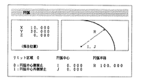
(円による領域の指定)
図1は、本発明の実施例の領域指定に用いるCRT等の表示指定画面において、円による領域を指定する指定画面を示している。図1においては、現在指定中の領域の形状が円であることが例えばタイトル表示によって示され、制御対象可動部の現在位置はX軸,Y軸,およびZ軸の座標データで示され、現在指定している形状が円の図形形状で示され、その円の中心の座標データがI,Jの値で、円の半径がRの値で示されている。また、円の内側を禁止領域とすることがリミット区域において、移動領域と禁止領域の選択によって示されている。
【0023】
なお、この現在指定している円の図形形状については、円の中心の座標データI,Jの値と、円の半径Rの値を入力して、その値に従って内部処理により図形を指定画面に表示することができる。なお、前記図形形状の指定において、工具の直径φを設定し、その工具の直径φを考慮して行うこともできる。
【0024】
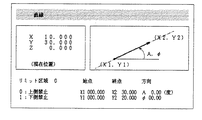
(直線による領域の指定)
図2は、本発明の実施例の領域指定に用いるCRT等の表示指定画面において、直線による領域を指定する指定画面を示している。図2においては、現在指定中の領域の形状が直線であることが例えばタイトル表示によって示され、制御対象可動部の現在位置は前記円による領域指定と同様にX軸,Y軸,およびZ軸の座標データで示され、現在指定している形状が直線の図形形状で示され、その直線の始点及び終点の座標データがX1,Y1およびX2,Y2により、あるいはその直線の始点の座標データX1,Y1および方向を示す角度Aによって示されている。なお、この直線は、前記2点あるいは1点と角度により定められる線分を両方向に延長したものとして設定される。また、φは、工具の直径を設定するものである。
【0025】
また、直線の上側を禁止領域とすることがリミット区域において、移動領域と禁止領域の選択によって示されている。なお、この実施例では、指定画面を正面に見て直線の上側あるいは下側によりリミット区域を指定しているが、指定画面を正面に見て直線の右側あるいは左側によりリミット区域を指定することも可能である。この現在指定している直線円の図形形状については、直線の始点及び終点の座標データがX1,Y1およびX2,Y2により、あるいはその直線の始点の座標データX1,Y1および方向を示す角度Aと工具の直径φを入力して、その値に従って内部処理により図形を指定画面に表示することができる。
【0026】
(円弧による領域の指定)
図3は、本発明の実施例の領域指定に用いるCRT等の表示指定画面において、円弧による領域を指定する指定画面を示している。図3においては、現在指定中の領域の形状が円弧であること例えばタイトル表示によってが示され、制御対象可動部の現在位置は前記円及び直線の場合と同様にX軸,Y軸,およびZ軸の座標データで示され、現在指定している形状が円弧の図形形状で示され、その円弧の中心の座標データがI,Jの値で、円弧の半径がRの値で示されている。また、円弧の中心が存在する側を禁止領域とすることがリミット区域において、移動領域と禁止領域の選択によって示されている。
【0027】
この現在指定している円弧の図形形状については、円弧の中心の座標データI,Jの値と、円弧の半径Rの値とを入力して、その値に従って内部処理により図形を指定画面に表示することができる。なお、前記図形形状の指定において、工具の直径φを設定し、その工具の直径φを考慮して行うこともできる。また、指定画面中に円弧の中心を表示できない場合には、仮の中心を表示することもできる。
【0028】
また、前記円による領域の指定、直線による領域の指定、あるいは円弧による領域の指定において、制御対象可動部の移動領域あるは禁止領域のリミット区域の区別を、指定画面において、色、模様、あるいは点滅表示等の表示手法により行うこともできる。
【0029】
(本発明の実施例の数値制御装置の構成)
次に、本発明の実施例を使用することができる数値制御装置の構成について、図4のブロック構成図を用いて説明する。なお、本発明の使用はこの数値制御装置に限定されるものではなく、他の領域指定を行う手段を有する装置に適用することができるものである。
【0030】
図4において、プロセッサ11は、ROM12に格納されたシステムプログラムに従って数値制御装置全体を制御する。このROM12のシステムプログラムによって実行されるソフトウエアは、図形記憶、補間等の機能を有している。このROM12には、EPROMあるいはEEPROMが使用される。RAM13にはSRAM等が使用され、入出力信号等の一時的なデータが格納される。不揮発性メモリ14には図示されないバッテリによってバックアップされたCMOSが使用される。また、不揮発性メモリ14には電源切断後も保存すべきパラメータ、加工プログラム等の各種データ等が格納される。
【0031】
グラフィック制御回路15はガイダンス情報や入力された指定形状等を表示可能な信号に変換し、表示装置16に与える。表示装置16にはCRTあるいは液晶表示装置が使用される。軸制御回路18(3軸分)は、プロセッサ11からの補間パルスCPを含む軸の移動指令を受けて、この軸の移動指令をサーボアンプ19(3軸分)に出力制御する。サーボアンプ19はこの移動指令を受け、工作機械20の図示されないサーボモータを駆動する。なお、工作機械20はこのサーボモータの他に、移動指令を行なうために操作する機械操作盤40を備えている。これらの構成要素はバス30によって互いに接続されている。
【0032】
PMC(プログラマブル・マシン・コントローラ)22は加工プログラムの実行時に、バス30を経由してT機能信号(工具選択指令)等を受け取る。そして、この信号をシーケンス・プログラムで処理して、動作指令として信号を出力し、工作機械20を制御する。また、工作機械20から状態信号を受け、シーケンス処理を行い、バス30を経由してプロセッサ11に必要な入力信号を転送する。
【0033】
なお、バス30には、さらにシステムプログラム等によって機能が変化するソフトウエアキー23が接続されている。そのソフトウエアキー23は、前記表示装置16、キーボード17とともに、CRT/MDIユニット25に設けられる。
【0034】
〔実施例の作用〕
次に、本発明の実施例の作用について説明する。
【0035】
(領域の指定)
はじめに、前記円、直線、あるいは円弧の指定基本図形を組み合わせることにより種々の領域の指定を行なう場合について説明する。
【0036】
(例1)図5および図6は、直線の領域を組み合わせることにより領域を指定する場合であり、図5はその指定画面を示し、図6はその領域指定の指定条件を示すものである。
【0037】
図5において、領域は3本の直線L1,L2,およびL3により領域を指定しており、この3本の直線により7つの領域P1〜P7に分割されている。ここで、例えば領域P1は、直線L1,L2,およびL3に対して全てその上側にある領域として設定され、この領域P1中の任意の点を座標(x,y)によって表すと、同じx座標に対する直線L1,L2,およびL3のY座標の値は、それぞれY1,Y2,Y3となる。そして、点(x,y)が領域P1中にある条件は、図6に示すように直線L1に対してはy>Y1、直線L2に対してはy>Y2、直線L3に対してはy>Y3の不等式が全て満足するときである。
【0038】
同様にして、他の領域P2〜P7においても、図6に示すような条件により領域の指定を行うことができる。
【0039】
なお、x座標に対する直線L1,L2,およびL3のY座標の値は、例えばそれぞれの直線L1,L2,およびL3を表す式にx座標を代入することにより求めることができるものであるが、この領域指定における不等式の条件式の演算は、プロセッサ11において行なうことができる。
【0040】
なお、前記領域指定において、直線L1〜L3により区切られて形成される全ての領域P1〜P7について図6に示すような領域指定の条件を設定する必要はなく、必要とする領域にのみ条件を入力してその領域のみの指定を行なうことができる。
【0041】
(例2)図7および図8は、直線の領域と円の領域を組み合わせることによって、領域を指定する場合であり、図7はその指定画面を示し、図8はその領域指定の指定条件を示すものである。
【0042】
図7において、領域は1本の直線Lおよび半径Rの1つの円Cにより領域を指定しており、この1本の直線と1つの円により4つの領域P11〜P14に分割されている。ここで、例えば領域P11は、直線Lに対して下側であり、かつ円Cの外側にある領域として設定される。また、領域P12は、直線Lに対して下側であり、かつ円Cの内側にある領域として設定され、この領域P12中の任意の点を座標(x,y)によって表すと、同じx座標に対する直線LのY座標の値はYとなる。また、この座標(x,y)の円Cの中心(I,J)との距離dはd=((x−I)2 +(y−J)2 )1/2 となる。そして、点(x,y)が領域P12中にある条件は、図8に示すように直線Lに対してはy<Y、円Cに対してはd<Rの条件が全て満足するときである。
【0043】
同様にして、他の領域P11,P13,P14においても、図8に示すように直線Lに対する不等式の条件と円Cに対する不等式の条件により領域の指定を行うことができる。
【0044】
なお、この領域の指定の条件式は、直線や円の定義式に応じて異なる形態の式によって表されることは明らかである。
【0045】
また、前記領域指定において、直線L及び円Cにより区切られて形成される全ての領域P11〜P14について、図8に示すような領域指定の条件を設定する必要はなく、必要とする領域にのみ条件を入力してその領域のみの指定を行なうことができる。
【0046】
(領域における移動制御)
次に、前記した本発明の領域指定の方法によって指定した移動領域あるいは禁止領域等の領域を用いて、制御対象可動部の移動の制御について図9〜図16を用いて説明する。
【0047】
図9は、本発明の実施例の指定領域での制御対象可動部の移動制御を説明するフローチャートであり、図10,11,12は移動指令が禁止領域から移動領域への脱出可能な方向か否かの判定を行なうフローチャートであり、図13〜図16は移動指令が禁止領域から移動領域への脱出可能な方向か否かの判定を説明する図である。
【0048】
はじめに、図9のフローチャートを用いて、指定領域での制御対象可動部の移動制御をステップSに従って説明する。
【0049】
ステップS1:はじめに、領域指定において制御対象可動部の移動が禁止されている禁止領域が指定されているかの判定を行なう。
【0050】
あらかじめ、表示装置16に表示された指定画面の表示状態を参照しながら、キーボード17等により領域の指定を行うと、この指定された領域のデータは不揮発性メモリ14に記憶される。プロセッサ11はこの不揮発性メモリ14を呼び出して、禁止領域の有無の判定を行なう。
【0051】
ステップS2:前記ステップS1の判定において、禁止領域が指定されている場合には、プロセッサ11は制御対象可動部の現在位置を検出し、その位置データを取得してRAM13等のメモリに記憶する。
【0052】
ステップS3:プロセッサ11は、制御対象可動部の目標位置のデータを不揮発性メモリ14を呼び出して求め、前記ステップS2で取得した現在位置とこの制御対象可動部の目標位置との間における数値制御装置の補間処理を行い、パルスモータを駆動するためのパルス計算を行ない、RAM13等のメモリに記憶する。
【0053】
ステップS4:次に、プロセッサ11はRAM13等のメモリに記憶されている現在位置の位置データを呼出し、不揮発性メモリ14等のメモリに記憶されている禁止領域のデータにより、その制御対象可動部の現在位置が禁止領域内か否かの判定を行なう。この判定は、禁止領域を指定している不等式等の条件式に制御対象可動部が現在存在する位置の位置データを適用することによって、行なうことができる。
【0054】
ステップS5:前記ステップS4の判定の結果、制御対象可動部の現在位置が禁止領域内でなく移動領域である場合には、プロセッサ11は、RAM13等のメモリに記憶されている制御対象可動部の目標位置のデータを読み出し、補間後の制御対象可動部の位置が禁止領域内か否かの判定を行なう。この判定においては、禁止領域を指定している不等式等の条件式に、補間後の制御対象可動部の位置データを適用することによって、行なうことができる。
【0055】
ステップS6:前記ステップS5の判定の結果、補間後の制御対象可動部の位置が禁止領域内となる場合には、現在位置と補間後の位置とを結ぶ線上において領域境界までのパルスを計算する。このパルス計算により、制御対象可動部を禁止領域に入る直前の領域の境界部分までの移動を行なわせるパルス信号を得ることができる。
【0056】
ステップS7:前記ステップS6の工程で求めた補間パルスを出力する。このパルス出力により、制御対象可動部を禁止領域に入る直前の領域の境界部分までの移動させることができる。
【0057】
ステップS10,7:また、前記ステップS1の判定において、制御対象可動部の移動が禁止された禁止領域が指定されていない場合には、制御対象可動部の移動領域における制限が存在しないため、補間処理を行って移動のためのパルス計算を行い、ステップS7においてその補間パルスを出力する。この補間パルスの出力により、制御対象可動部は目的とする移動位置への移動が行なわれる。
【0058】
ステップS8:前記ステップS4の判定において、制御対象可動部の現在位置が禁止領域内である場合には、そのとき指令されている移動指令の方向に向かって制御対象可動部を移動させた場合に、制御対象可動部が禁止領域から移動領域に入るか否かの判定を行なう。そのために、移動指令の方向が制御対象可動部を禁止領域から脱出させる方向か否かの判定を行なう。
【0059】
移動指令の方向が制御対象可動部を禁止領域から脱出させる方向である場合には、前記ステップS3の工程で計算したパルスを用い、ステップS7においてパルス出力を行い移動を実行する。
【0060】
なお、この移動指令の方向の判定については、後述する(移動指令の方向判定)の項において図10〜図16を用いて説明する。
【0061】
ステップS9:前記ステップS8の判定において、移動指令の方向が制御対象可動部を禁止領域から脱出させる方向でない場合には、前記ステップS3の工程で計算した補間パルスをクリアして処理を終了する。
【0062】
(移動指令の方向判定)
次に、前記ステップS8における移動指令の方向を調べ、その移動方向が制御対象可動部を禁止領域から移動領域へ移動させるものか否かの判定を行なう。
【0063】
以下、領域指定が円の場合に適用されるフローの一実施例と、領域指定が直線の場合の場合に適用されるフローの一実施例、および領域が円、直線、および円弧の場合に適用されるフローの一実施例について説明する。
【0064】
(1)はじめに、領域指定が円の場合で、領域の外側が禁止領域である場合に適用したフローの一実施例について、図10のフローチャートを用いて、ステップSの10番台の符号を用いて説明する。
【0065】
ステップS11:移動指令および補間パルスに基づき、制御対象可動部のある時点における移動位置を求める。
【0066】
ステップS12:前記ステップS11で求めた制御対象可動部の移動位置と円の中心との間のある時点での距離di と、次の時点での距離di+1 を求める。これにより微小時間での制御対象可動部の移動状態を検出することができる。
【0067】
ステップS13:前記ステップS12で求めたある時点の距離di と、次の時点での距離di+1 とを比較し、制御対象可動部が円の中心方向に進んでいるか否かの判定を行なう。
【0068】
ステップS14:ある時点の距離di が次の時点での距離di+1 よりも大きくなる場合には、制御対象可動部は円の中心方向から遠ざかる方向に進んでいるため、前記ステップS3において求めた補間パルスをクリアして移動を行なわない。この工程は図9の前記ステップS9に対応するものである。
【0069】
ステップS15:ある時点の距離di が次の時点での距離di+1 よりも小さくなる場合には、制御対象可動部は円の中心方向に近づく方向に進んでいる。そこで、補間パルスを出力して移動を行う。この工程は図9の前記ステップS7に対応するものである。
【0070】
ステップS16:さらにステップS11からステップS13の工程を繰り返して、制御対象可動部が円内に侵入する補間パルス数を求める。この制御対象可動部が円内に侵入したか否かの判定は、距離di+1 と円の半径Rとの大きさの比較により行なわれる。
【0071】
前記フローの例を図14および図15に示す領域指定が円の場合の移動指令の方向判定を説明する図を用いて説明する。
【0072】
例えば、図14は円の内側を移動領域とし外側を禁止領域としたときに、移動指令の方向が禁止領域から移動領域に脱出する方向である場合を示したものである。移動指令の移動方向を破線により示しており、この破線は円と交差している。ここで、移動の軌跡上の点と円の中心との距離dは、移動に応じて順に小さくなり、ある時点において円周上に到達する。この到達点は領域の境界に対応するものであり、さらに移動することにより禁止領域から移動領域に脱出することができる。
【0073】
また、図15は図14と同様に、円の内側を移動領域とし外側を禁止領域としたときに、移動指令の方向が禁止領域から移動領域に脱出する方向である場合を示したものであるが、図示するように破線で示す移動方向と円とは交差していない。ここで、移動の軌跡上の点と円の中心との距離dは、移動に応じて順に小さくなるが、ある時点を通過すると以後はその距離dが増加する。したがって、この移動指令による移動では、禁止領域から移動領域に脱出することはできない。そして、円の中心に最も接近する時点において停止することになる。
【0074】
(2)次に、領域指定が直線の場合で、領域の外側が禁止領域である場合に適用したフローの一実施例について、図11のフローチャートを用いて、ステップSの20番台の符号を用いて説明する。
【0075】
ステップS21:移動指令および補間パルスに基づき、制御対象可動部のある時点における移動位置を求める。
【0076】
ステップS22:前記ステップS11で求めた制御対象可動部の移動位置と直線とのある時点での距離di と、次の時点での距離di+1 を求める。これにより微小時間での制御対象可動部の移動状態を検出することができる。なお、この直線との距離は、点から直線への法線の長さを求めることにより得られる。
【0077】
ステップS23:前記ステップS22で求めたある時点の距離di と、次の時点での距離di+1 とを比較し、制御対象可動部が直線に接近する方向に進んでいるか否かの判定を行なう。
【0078】
ステップS24:ある時点の距離di が次の時点での距離di+1 よりも小さくなる場合には、制御対象可動部は直線から遠ざかる方向に進んでいるため、前記ステップS23において求めた補間パルスをクリアして移動を行なわない。この工程は図9の前記ステップS9に対応するものである。
【0079】
ステップS25:ある時点の距離di が次の時点での距離di+1 よりも大きくなる場合には、制御対象可動部は直線に近づく方向に進んでいる。そこで、補間パルスを出力する。この工程は図9の前記ステップS7に対応するものである。
【0080】
ステップS26:さらにステップS21からステップS23の工程を繰り返して、制御対象可動部が直線と交差する補間パルス数を求める。この制御対象可動部が移動領域内に侵入したか否かの判定は、距離di+1 が0となるか否かの比較により行われる。
【0081】
前記フローの例を、図16に示す領域指定が直線の場合の移動指令の方向判定を説明する図を用いて説明する。
【0082】
例えば、図16は直線の上側を移動領域とし下側を禁止領域としたときに、移動指令の方向が禁止領域から移動領域に脱出する方向である場合を示したものである。移動指令の移動方向を破線により示しており、この破線は直線と交差している。ここで、移動の軌跡上の点と直線との距離dは、移動に応じて順に小さくなり、ある時点において直線と交差する。この交点は領域の境界に対応するものであり、さらに移動することにより禁止領域から移動領域に脱出することができる。
【0083】
なお、図16において、破線の移動方向を逆方向にとると、移動の軌跡上の点と直線との距離dは、移動に応じて順に大きくなり、この移動指令による移動では、禁止領域から移動領域に脱出することはできない。
【0084】
(3)次に、領域指定が円、直線、あるいは円弧の場合に適用されるフローの一実施例について、図13の移動指令が禁止領域から移動領域に脱出することがでるかの説明図、および図12のフローチャートを用いて、ステップSの30番台の符号を用いて説明する。
【0085】
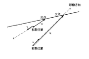
ステップS31:移動指令および補間パルスに基づき、移動方向の延長上に領域指定の境界があるか否かを判定する。この判定においては、円、直線、あるいは円弧と移動方向の直線との交点の有無を判定することにより行なわれる。
【0086】
ステップS32:次に、移動方向の初期位置と前記ステップS31の工程で求めた交点とによりベクトルuを求める。例えば、図13において、初期位置から交点を結ぶベクトルuを太い実線により示している。
【0087】
ステップS33:さらに、移動指令の移動方向の単位ベクトルvを求め、この単位ベクトルvと前記ステップS32のベクトルuとの内積を求める。
【0088】
ステップS34:前記ステップS33で求めた内積の値の正負を判定する。これにより移動方向と、初期位置から交点への方向の関係を判定することができる。つまり、内積が正の場合には、移動方向は初期位置から交点への方向と同じであり、一方、内積が負の場合には、移動方向は初期位置から交点への方向と逆方向である。
【0089】
ステップS35:内積が負の場合には、移動方向は初期位置から交点への方向と逆方向であるため、補間パルスをクリアして移動を行なわない。この工程は図9の前記ステップS9に対応するものである。
【0090】
ステップS36:内積が正の場合には、移動方向は初期位置から交点への方向と同じであるため、補間パルスを出力する。この工程は図9の前記ステップS7に対応するものである。
【0091】
(実施例の工作機械への適用例)
次に、本発明の実施例を工作機械に適用した場合を説明する。
【0092】
はじめに、直線の領域を指定した場合の例について、図17を用いて説明する。図において、XY座標軸平面上には、指定領域として直線110によりその上側を禁止領域に指定している。この直線110は、例えば不揮発性メモリ14に記憶しておき、プロセッサ11によって呼び出し可能となっている。また、工具111はその中心が位置Q1にあり、工具113はその中心が位置Q3にある。
【0093】
このとき、工作機械20の機械操作盤40において並行移動を選択し、ジョグ送りあるいはハンドル送りを行なう。これにより、工具110は直線110と平行に方向111aあるいは方向111bに移動する。
【0094】
また、工作機械20の機械操作盤40において垂直移動を選択し、ジョグ送りあるいは手動パルス発生器41によりハンドル送りを行なうと、直線110に対して法線方向に方向113aあるいは方向113bに移動する。
【0095】
なお、この工具の移動は、所定の座標値の入力により補間パルスの出力を停止する機能を付加することも可能である。
【0096】
また、図18を用いて、円弧の領域を指定した場合の例について説明する。図において、XY座標軸平面上には、指定領域として円弧120によりその上側を禁止領域に指定している。この円弧120は、例えば不揮発性メモリ14に記憶しておき、プロセッサ11によって呼び出し可能となっている。また、工具121はその中心が位置Q5にあり、工具122はその中心が位置Q6にある。
【0097】
このとき、工作機械20の機械操作盤40において並行移動を選択し、ジョグ送りあるいは手動パルス発生器41によりハンドル送りを行なう。これにより、工具121は円弧120と一定の間隔を保持して方向121aあるいは方向121bに移動する。この場合の一定間隔は、工具の位置121と円弧120との間の法線成分である。
【0098】
また、工作機械20の機械操作盤40において垂直移動を選択し、ジョグ送りあるいはハンドル送りを行なうと、円弧120に対して法線方向に方向122aあるいは方向122bに移動する。
【0099】
(本発明の実施例の効果)
前記構成によって、実施例においては、直線、円、あるい円弧の基本的な指定形状によって、加工領域を容易に設定することができる。
【0100】
(変形例)
なお、本発明は上記実施例に限定されるものではなく、本発明の趣旨に基づき種々の変形が可能であり、それらを本発明の範囲から排除するものではない。
【0101】
前記実施例においては、円による領域指定、直線による領域指定、あるいは円弧による領域指定、およびそれらの領域の組み合わせにより、制御対象可動部の移動領域あるは禁止領域の領域指定を行っているが、複数の直線の組み合わせによる多角形の領域指定においては、あらかじめ多角形の領域を設定しておき、その多角形の領域を用いて領域指定を行うこともできる。
【0102】
また、使用頻度等の必要に応じて円、直線、円弧等の基本図形を組み合わせた図形を設定しておくことも可能である。
【0103】
【発明の効果】
以上説明したように、本発明によれば、制御対象可動部の移動位置あるいは移動限界についての位置情報を数値データとして厳密に定義することなく、制御対象可動部の移動領域あるは禁止領域の領域指定を容易に行うことができる。
【図面の簡単な説明】
【図1】本発明の実施例の円による領域を指定する設定画面を説明する図である。
【図2】本発明の実施例の直線による領域を指定する設定画面を説明する図である。
【図3】本発明の実施例の円弧による領域を指定する設定画面を説明する図である。
【図4】本発明の実施例を使用することができる数値制御装置のブロック構成図である。
【図5】直線の領域を組み合わせることにより領域を指定する指定画面である。
【図6】直線の領域を組み合わせることにより領域を指定する指定条件を示す表である。
【図7】円の領域を組み合わせることにより領域を指定する指定画面である。
【図8】円の領域を組み合わせることにより領域を指定する指定条件を示す表である。
【図9】本発明の実施例の指定領域での制御対象可動部の移動制御を説明するフローチャートである。
【図10】本発明の移動指令が禁止領域から移動領域への脱出可能な方向か否かの判定を行なうフローチャートである。
【図11】本発明の移動指令が禁止領域から移動領域への脱出可能な方向か否かの判定を行なうフローチャートである。
【図12】本発明の移動指令が禁止領域から移動領域への脱出可能な方向か否かの判定を行なうフローチャートである。
【図13】本発明の移動指令が禁止領域から移動領域への脱出可能な方向か否かの判定を説明する図である。
【図14】本発明の移動指令が禁止領域から移動領域への脱出可能な方向か否かの判定を説明する図である。
【図15】本発明の移動指令が禁止領域から移動領域への脱出可能な方向か否かの判定を説明する図である。
【図16】本発明の移動指令が禁止領域から移動領域への脱出可能な方向か否かの判定を説明する図である。
【図17】本発明の直線の領域指定を工作機械に適用した場合を説明する図である。
【図18】本発明の円の領域指定を工作機械に適用した場合を説明する図である。
【符号の説明】
11 プロセッサ
12 ROM
13 RAM
14 不揮発性メモリ
15 グラフィック制御回路
16 表示装置
17 キーボード
18 軸制御回路
19 サーボアンプ
20 工作機械
22 PMC
23 ソフトウエアキー
25 CRT/MDIユニット
30 バス
40 機械操作盤[0001]
[Industrial applications]
The present invention relates to a method for designating an area such as a movement area or a prohibited area of a controlled movable section.
[0002]
[Prior art]
In general, in a numerical control device or the like that performs machining by controlling the movement of a table or a turret of a machine tool such as a lathe or a machining center, a moving position of a movable portion to be controlled is designated as numerical data, and a moving limit is specified. Is designated as numerical data, thereby setting a machining area, preventing interference with other mechanical members, preventing runaway of a movable member, and the like.
[0003]
Conventionally, in the specification of the movement position and the movement limit of the controlled object movable part, in addition to the coordinate data such as the machine coordinates, the machine origin, the program coordinates, and the processing origin, the movement position or the movement limit of the controlled object movable part is specified. Information is accurately defined as numerical data, and a program for giving a work instruction such as a machining program is created using the numerical data.
[0004]
[Problems to be solved by the invention]
However, in the above-described conventional method of designating an area relating to the movement of the controlled object movable part, since it is necessary to accurately define the position information of the movement position or the movement limit of the controlled object movable part as numerical data, many calculation operations are required. There is a problem that it requires a large amount.
[0005]
In addition, due to the increase in the amount of work in the area specification relating to the movement of the controlled movable part, the amount of work for creating a work program such as the area processing formed using the data becomes enormous, and the work of the area processing and the like becomes large. There is also a secondary problem that the efficiency is reduced.
[0006]
Therefore, the present invention solves the problem of the above-described conventional method of specifying the area, and does not perform the operation of strictly defining the position information on the movement position or the movement limit of the controlled object movable portion as numerical data, without performing the operation of the control object. It is an object of the present invention to easily specify a moving area or a prohibited area of a movable part.
[0007]
[Means for Solving the Problems]
The present invention, in order to achieve the above object,A step of inputting all the straight lines or circles constituting the boundary shape of the movable area, and a step of designating which of the two planes divided by the straight line or the circle is the movable area. Determining whether the current position of the control target movable unit belongs to a specified movable region; and determining whether the position after interpolation of the movable unit belongs to a specified movable region. The step of executing the movement of the movable part if both the current position of the movable part and the position after interpolation belong to the movable area; and the current position of the movable part belongs to the movable area and the position of the movable part after interpolation. Executing the movement to the straight line or the circle when the position does not belong to the movable region.
[0008]
Further, when the current position of the movable unit does not belong to the movable region and the position after interpolation of the movable unit belongs to the movable region, the method includes a step of executing the movement of the movable unit.
[0011]
[Action]
According to the present invention, by adopting the above configuration,By inputting all the straight lines or circles that constitute the boundary shape of the movable area and specifying which of the two planes divided by the input straight line or circle is the movable area, the movable area can be designated.
[0012]
Then, it is determined whether or not the current position of the control target movable section belongs to the designated movable area, and whether or not the position after interpolation of the movable section belongs to the designated movable area is determined. When both the current position of the unit and the position after interpolation belong to the movable region, the movement of the movable unit is executed. Further, when the current position of the movable part belongs to the movable area and the position after interpolation of the movable part does not belong to the movable area, the movement to the straight line or the circle is executed.
[0013]
Further, when the current position of the movable part does not belong to the movable area and the position after interpolation of the movable part belongs to the movable area, the movement of the movable part is executed.
[0014]
【Example】
Hereinafter, embodiments of the present invention will be described in detail with reference to the drawings, but the present invention is not limited to the embodiments.
[0015]
[Configuration of Example of the Present Invention]
FIG. 1 is a diagram for explaining a setting screen for specifying a region by a circle according to the embodiment of the present invention. FIG. 2 is a diagram for explaining a setting screen for specifying a region by a straight line according to the embodiment of the present invention. FIG. 5 is a diagram illustrating a setting screen for designating a region by an arc according to the embodiment of the present invention.
[0016]
The region designation in the embodiment of the present invention is performed by using a basic graphic region designation such as a region designation by a circle, a region designation by a straight line, or a region designation by an arc.
[0017]
In specifying a region by a circle, for example, a circle is defined by inputting the center coordinates of the circle and the radius of the circle, and the region is specified by specifying the inside or outside of the circle. In specifying an area by a straight line, for example, a straight line is defined by inputting the coordinates of two points or inputting the coordinates of one point and the angle of a line segment, and specifying the area by specifying the top, bottom, left and right of the straight line. Do. In specifying an area by an arc, for example, the arc is defined by inputting the center coordinates of the arc and the radius of the arc, and the area is specified by specifying the same side or the opposite side of the center point of the arc. .
[0018]
The other areas can be specified by combining basic figures such as the above-described area specification using a circle, the area specification using a straight line, or the area specification using an arc. For example, a triangular area can be achieved by combining three linear areas.
[0019]
In the embodiment of the present invention, this area is designated on a display designation screen such as a CRT. 1 to 3 show one embodiment of the display designation screen. In the display specification screen shown in the figure, a part that displays the currently specified shape, a part that shows the current position of the controlled movable part, a part that displays the specified graphic, and data that defines the specified graphic And a part for setting which area of the designated graphic is to be the movement area or the prohibited area of the control target movable part.
[0020]
Then, in the portion indicating the current position of the controlled object movable portion of the display designation screen, the current position is displayed by position data from a control device (not shown) of the controlled object movable portion, and for the other portions, The display is performed according to an input value from an input device (not shown).
[0021]
Hereinafter, an area specification using a basic figure, which is an example of specifying an area using a circle, specifying an area using a straight line, or specifying an area using an arc in the embodiment of the present invention, will be described with reference to FIGS.
[0022]
(Designation of area by circle)
FIG. 1 shows a designation screen for designating a region by a circle in a display designation screen of a CRT or the like used for region designation according to the embodiment of the present invention. In FIG. 1, for example, it is indicated by a title display that the shape of the currently designated area is a circle, and the current position of the control target movable unit is indicated by coordinate data of the X axis, the Y axis, and the Z axis. The designated shape is indicated by a graphic shape of a circle, the coordinate data of the center of the circle is indicated by I and J values, and the radius of the circle is indicated by R value. In the limit area, the selection of the movement area and the prohibited area indicates that the inside of the circle is the prohibited area.
[0023]
For the figure shape of the currently designated circle, the values of the coordinate data I and J of the center of the circle and the value of the radius R of the circle are input, and the figure is displayed on the designation screen by internal processing according to the values. Can be displayed. The designation of the figure shape may be performed by setting a tool diameter φ and taking the tool diameter φ into consideration.
[0024]
(Designation of area by straight line)
FIG. 2 shows a designation screen for designating a region by a straight line on a display designation screen such as a CRT used for region designation according to the embodiment of the present invention. In FIG. 2, for example, a title display indicates that the shape of the currently designated area is a straight line, and the current position of the movable object to be controlled is the X-axis, Y-axis, and Z-axis similarly to the area designation by the circle. The currently specified shape is indicated by a linear graphic shape, and the coordinate data of the start point and end point of the straight line is represented by X1, Y1 and X2, Y2, or the coordinate data X1 of the start point of the straight line , Y1 and an angle A indicating the direction. This straight line is set as a line segment defined by the two points or one point and the angle and extended in both directions. Φ sets the diameter of the tool.
[0025]
In the limit area, the selection of the movement area and the prohibited area indicates that the upper side of the straight line is the prohibited area. In this embodiment, the limit area is specified by the upper or lower side of the straight line when the specified screen is viewed from the front, but the limit area may be specified by the right or left side of the straight line when the specified screen is viewed from the front. It is possible. Regarding the graphic shape of the currently specified straight line circle, the coordinate data of the start point and the end point of the straight line is represented by X1, Y1 and X2, Y2, or the coordinate data X1, Y1 of the start point of the straight line and the angle A indicating the direction. By inputting the diameter φ of the tool, the figure can be displayed on the designated screen by internal processing according to the value.
[0026]
(Specification of area by arc)
FIG. 3 shows a designation screen for designating a region by an arc in a display designation screen of a CRT or the like used for region designation according to the embodiment of the present invention. In FIG. 3, the shape of the currently designated area is a circular arc, for example, is indicated by a title display, and the current position of the control target movable unit is the X axis, the Y axis, and the Z axis as in the case of the circle and the straight line. The coordinate data of the axis is shown, the currently designated shape is shown by a figure shape of an arc, the coordinate data of the center of the arc is shown by I and J values, and the radius of the arc is shown by R value. . In the limit area, the selection of the movement area and the prohibited area indicates that the side where the center of the arc exists is the prohibited area.
[0027]
With respect to the figure shape of the currently specified arc, the coordinate data I and J of the center of the arc and the value of the radius R of the arc are input, and the figure is displayed on the specification screen by internal processing according to the values. can do. The designation of the figure shape may be performed by setting a tool diameter φ and taking the tool diameter φ into consideration. If the center of the arc cannot be displayed on the designated screen, a temporary center can be displayed.
[0028]
Further, in the specification of the area by the circle, the specification of the area by a straight line, or the specification of the area by an arc, the distinction between the movement area of the controlled object movable part or the limit area of the prohibited area is performed by specifying the color, pattern, or It can also be performed by a display method such as blinking display.
[0029]
(Configuration of Numerical Controller of Embodiment of the Present Invention)
Next, the configuration of a numerical control device that can use the embodiment of the present invention will be described with reference to the block diagram of FIG. The use of the present invention is not limited to this numerical control device, but can be applied to a device having another means for specifying an area.
[0030]
In FIG. 4, a
[0031]
The
[0032]
A PMC (programmable machine controller) 22 receives a T function signal (tool selection command) and the like via the
[0033]
The
[0034]
[Operation of the embodiment]
Next, the operation of the embodiment of the present invention will be described.
[0035]
(Specify area)
First, a description will be given of a case where various areas are specified by combining the above-described circle, straight line, or arc specification basic figures.
[0036]
(Example 1) FIGS. 5 and 6 show a case where an area is specified by combining straight-line areas. FIG. 5 shows a specification screen thereof, and FIG. 6 shows a specification condition of the area specification.
[0037]
In FIG. 5, the region is designated by three straight lines L1, L2, and L3, and is divided into seven regions P1 to P7 by these three straight lines. Here, for example, the area P1 is set as an area above the straight lines L1, L2, and L3, and an arbitrary point in the area P1 is represented by coordinates (x, y). Are Y1, Y2, and Y3, respectively. The condition that the point (x, y) is in the area P1 is that y> Y1 for the straight line L1, y> Y2 for the straight line L2, and y for the straight line L3 as shown in FIG. > Y3 when all the inequalities are satisfied.
[0038]
Similarly, in the other areas P2 to P7, the area can be designated under the conditions shown in FIG.
[0039]
Note that the value of the Y coordinate of the straight lines L1, L2, and L3 with respect to the x coordinate can be obtained by substituting the x coordinate into the equations representing the straight lines L1, L2, and L3, for example. The calculation of the inequality conditional expression in the area specification can be performed by the
[0040]
In the area specification, it is not necessary to set the area specification conditions as shown in FIG. 6 for all the areas P1 to P7 formed by being separated by the straight lines L1 to L3. By inputting, only the area can be designated.
[0041]
(Example 2) FIGS. 7 and 8 show a case where an area is designated by combining a linear area and a circle area. FIG. 7 shows a designation screen thereof, and FIG. It is shown.
[0042]
In FIG. 7, the area is designated by one straight line L and one circle C of radius R, and is divided into four areas P11 to P14 by this one straight line and one circle. Here, for example, the region P11 is set as a region below the straight line L and outside the circle C. The region P12 is set as a region below the straight line L and inside the circle C. When an arbitrary point in the region P12 is represented by coordinates (x, y), the same x coordinate is used. The value of the Y coordinate of the straight line L with respect to The distance d between the coordinates (x, y) and the center (I, J) of the circle C is d = ((x−I)2+ (Y-J)2)1/2It becomes. The condition in which the point (x, y) is in the area P12 is when all the conditions of y <Y for the straight line L and d <R for the circle C are satisfied, as shown in FIG. is there.
[0043]
Similarly, in the other regions P11, P13, and P14, the regions can be designated based on the inequality condition for the straight line L and the inequality condition for the circle C as shown in FIG.
[0044]
It is obvious that the conditional expression for designating this area is represented by an expression having a different form according to the definition expression of a straight line or a circle.
[0045]
Further, in the area specification, it is not necessary to set the area specification conditions as shown in FIG. 8 for all the areas P11 to P14 formed by being separated by the straight line L and the circle C, and only to the necessary areas. A condition can be input to specify only that area.
[0046]
(Moving control in the area)
Next, the control of the movement of the control-target movable section using the movement area or the prohibited area specified by the above-described area specification method of the present invention will be described with reference to FIGS.
[0047]
FIG. 9 is a flowchart for explaining the movement control of the control target movable portion in the designated area according to the embodiment of the present invention. FIGS. FIG. 13 to FIG. 16 are diagrams for explaining the determination as to whether or not the movement command is in a direction allowing escape from the prohibited area to the movement area.
[0048]
First, the movement control of the control target movable portion in the designated area will be described according to step S with reference to the flowchart in FIG.
[0049]
Step S1: First, it is determined whether or not a prohibited area in which movement of the control target movable unit is prohibited is specified in the area specification.
[0050]
When an area is designated by the
[0051]
Step S2: If the prohibited area is specified in the determination in step S1, the
[0052]
Step S3: The
[0053]
Step S4: Next, the
[0054]
Step S5: As a result of the determination in step S4, if the current position of the control target movable unit is not in the prohibited area but in the movement area, the
[0055]
Step S6: If the result of the determination in step S5 is that the position of the control-target movable section after interpolation falls within the prohibited area, a pulse up to the area boundary is calculated on a line connecting the current position and the position after interpolation. . By this pulse calculation, it is possible to obtain a pulse signal for moving the controlled movable section to the boundary portion of the area immediately before entering the prohibited area.
[0056]
Step S7: Output the interpolation pulse obtained in the step S6. With this pulse output, the controlled object movable portion can be moved to the boundary portion of the region immediately before entering the prohibited region.
[0057]
Steps S10 and S7: If the prohibited area in which the movement of the controlled object movable part is prohibited is not specified in the determination in step S1, there is no restriction in the movement area of the controlled object movable part, and therefore interpolation is performed. Processing is performed to calculate a pulse for movement, and the interpolation pulse is output in step S7. By the output of the interpolation pulse, the controlled object movable portion is moved to a target movement position.
[0058]
Step S8: If the current position of the controlled object movable part is within the prohibited area in the determination of the step S4, the controlled object movable part is moved in the direction of the movement command instructed at that time. Then, it is determined whether or not the control target movable section enters the movement area from the prohibited area. For this purpose, it is determined whether or not the direction of the movement command is a direction in which the control-target movable unit escapes from the prohibited area.
[0059]
If the direction of the movement command is a direction in which the control target movable section escapes from the prohibited area, a pulse is output in step S7 using the pulse calculated in step S3, and the movement is performed.
[0060]
The determination of the direction of the movement command will be described later in the section (movement command direction determination) with reference to FIGS.
[0061]
Step S9: If it is determined in step S8 that the direction of the movement command is not the direction in which the control target movable unit escapes from the prohibited area, the interpolation pulse calculated in step S3 is cleared, and the process ends.
[0062]
(Movement command direction judgment)
Next, the direction of the movement command in step S8 is checked, and it is determined whether or not the movement direction is to move the controlled movable section from the prohibited area to the movement area.
[0063]
Hereinafter, an example of a flow applied when the area specification is a circle, an example of a flow applied when the area specification is a straight line, and an example of the flow applied when the area is a circle, a line, and an arc An example of the flow performed will be described.
[0064]
(1) First, an example of a flow applied when the area designation is a circle and the outside of the area is a prohibited area is described by using the 10's code in step S using the flowchart of FIG. explain.
[0065]
Step S11: Based on the movement command and the interpolation pulse, a movement position at a certain point in time of the movable part to be controlled is obtained.
[0066]
Step S12: a distance d at a certain point between the movement position of the controlled object movable portion obtained in step S11 and the center of the circleiAnd the distance d at the next timei + 1Ask for. This makes it possible to detect the moving state of the control target movable portion in a very short time.
[0067]
Step S13: the distance d at a certain point in time obtained in step S12iAnd the distance d at the next timei + 1To determine whether or not the control target movable portion is moving toward the center of the circle.
[0068]
Step S14: Distance d at a certain timeiIs the distance d at the next timei + 1If it is larger, the control target movable portion is moving in a direction away from the center of the circle, so that the interpolation pulse obtained in step S3 is cleared and no movement is performed. This step corresponds to step S9 in FIG.
[0069]
Step S15: Distance d at a certain timeiIs the distance d at the next timei + 1If it becomes smaller, the controlled object movable portion is moving in a direction approaching the center of the circle. Therefore, the movement is performed by outputting the interpolation pulse. This step corresponds to step S7 in FIG.
[0070]
Step S16: Further, the steps from step S11 to step S13 are repeated to obtain the number of interpolation pulses at which the control target movable portion enters the circle. The determination as to whether or not the control target movable portion has entered the circle is made based on the distance d.i + 1This is performed by comparing the size of the circle with the radius R of the circle.
[0071]
An example of the flow will be described with reference to FIGS. 14 and 15 illustrating the direction determination of the movement command when the area designation is a circle.
[0072]
For example, FIG. 14 shows a case where the direction of the movement command is a direction to escape from the prohibited area to the moving area when the inside of the circle is the moving area and the outside is the prohibited area. The movement direction of the movement command is indicated by a broken line, and the broken line intersects with the circle. Here, the distance d between the point on the locus of movement and the center of the circle decreases in order according to the movement, and reaches the circumference at a certain point. This arrival point corresponds to the boundary of the area, and by moving further, it is possible to escape from the prohibited area to the movement area.
[0073]
Further, FIG. 15 shows a case where the direction of the movement command is a direction of escape from the prohibited area to the moving area when the inside of the circle is the moving area and the outside is the prohibited area, as in FIG. However, as shown, the moving direction indicated by the broken line does not intersect the circle. Here, the distance d between a point on the path of movement and the center of the circle decreases in order according to the movement, but after a certain point in time, the distance d increases thereafter. Therefore, it is not possible to escape from the prohibited area to the movement area by the movement according to the movement command. Then, the vehicle stops when it approaches the center of the circle most.
[0074]
(2) Next, an example of a flow applied when the area designation is a straight line and the outside of the area is a forbidden area will be described using the codes in the 20's in step S using the flowchart of FIG. Will be explained.
[0075]
Step S21: Based on the movement command and the interpolation pulse, a movement position of the control target movable portion at a certain time is obtained.
[0076]
Step S22: Distance d at a certain point between the moving position of the controlled object movable part obtained in step S11 and the straight lineiAnd the distance d at the next timei + 1Ask for. This makes it possible to detect the moving state of the control target movable portion in a very short time. The distance from the straight line can be obtained by determining the length of the normal from the point to the straight line.
[0077]
Step S23: the distance d at a certain point in time obtained in step S22iAnd the distance d at the next timei + 1To determine whether or not the control target movable portion is moving in a direction approaching a straight line.
[0078]
Step S24: Distance d at a certain timeiIs the distance d at the next timei + 1If it becomes smaller, the control target movable portion is moving in a direction away from the straight line, so that the interpolation pulse obtained in step S23 is cleared and no movement is performed. This step corresponds to step S9 in FIG.
[0079]
Step S25: Distance d at a certain timeiIs the distance d at the next timei + 1If it becomes larger, the controlled object movable portion is moving in a direction approaching a straight line. Therefore, an interpolation pulse is output. This step corresponds to step S7 in FIG.
[0080]
Step S26: Further, the steps from step S21 to step S23 are repeated to obtain the number of interpolation pulses at which the controllable movable section intersects the straight line. The determination as to whether or not the control target movable portion has entered the moving area is made based on the distance d.i + 1Is determined by comparing whether or not becomes zero.
[0081]
An example of the above flow will be described with reference to FIG. 16 which illustrates the direction determination of the movement command when the area designation is a straight line.
[0082]
For example, FIG. 16 illustrates a case where the direction of the movement command is a direction of escape from the prohibited area to the moving area when the upper side of the straight line is the moving area and the lower side is the prohibited area. The movement direction of the movement command is indicated by a broken line, and the broken line intersects the straight line. Here, the distance d between a point on the path of the movement and the straight line decreases in order according to the movement, and intersects the straight line at a certain point. This intersection corresponds to the boundary of the area, and by moving further, it is possible to escape from the prohibited area to the movement area.
[0083]
In FIG. 16, when the moving direction of the broken line is taken in the opposite direction, the distance d between the point on the locus of the movement and the straight line increases in order according to the movement. You cannot escape into the realm.
[0084]
(3) Next, regarding one embodiment of a flow applied when the area designation is a circle, a straight line, or an arc, an explanatory diagram showing whether the movement command in FIG. 13 can escape from the prohibited area to the movement area, This will be described with reference to the flowcharts of FIG. 12 and the reference numerals in the thirties in step S.
[0085]
Step S31: Based on the movement command and the interpolation pulse, it is determined whether or not there is an area designation boundary on the extension of the movement direction. This determination is made by determining whether there is an intersection between a circle, a straight line, or an arc and a straight line in the movement direction.
[0086]
Step S32: Next, a vector u is obtained from the initial position in the moving direction and the intersection obtained in the step S31. For example, in FIG. 13, a vector u connecting the intersection from the initial position is indicated by a thick solid line.
[0087]
Step S33: Further, a unit vector v in the movement direction of the movement command is obtained, and an inner product of the unit vector v and the vector u in step S32 is obtained.
[0088]
Step S34: It is determined whether the value of the inner product obtained in step S33 is positive or negative. Thereby, the relationship between the moving direction and the direction from the initial position to the intersection can be determined. In other words, when the inner product is positive, the moving direction is the same as the direction from the initial position to the intersection, while when the inner product is negative, the moving direction is opposite to the direction from the initial position to the intersection. .
[0089]
Step S35: If the inner product is negative, the movement direction is opposite to the direction from the initial position to the intersection, so the interpolation pulse is cleared and no movement is performed. This step corresponds to step S9 in FIG.
[0090]
Step S36: If the inner product is positive, an interpolation pulse is output because the moving direction is the same as the direction from the initial position to the intersection. This step corresponds to step S7 in FIG.
[0091]
(Example of application of the embodiment to machine tools)
Next, a case where the embodiment of the present invention is applied to a machine tool will be described.
[0092]
First, an example in the case where a straight line region is designated will be described with reference to FIG. In the figure, on the XY coordinate axis plane, a
[0093]
At this time, parallel movement is selected on the machine operation panel 40 of the machine tool 20, and jog feed or handle feed is performed. Thereby, the
[0094]
Further, when vertical movement is selected on the machine operation panel 40 of the machine tool 20 and the handle is fed by the jog feed or the
[0095]
The movement of the tool can be provided with a function of stopping the output of the interpolation pulse by inputting a predetermined coordinate value.
[0096]
An example in the case where an arc region is specified will be described with reference to FIG. In the figure, on the XY coordinate axis plane, the upper side is designated as a forbidden area by a circular arc 120 as a designated area. The arc 120 is stored in, for example, the
[0097]
At this time, the parallel movement is selected on the machine operation panel 40 of the machine tool 20, and the jog feed or the
[0098]
When vertical movement is selected on the machine operation panel 40 of the machine tool 20 and jog feed or handle feed is performed, the circular arc 120 is moved in the
[0099]
(Effects of the embodiment of the present invention)
With the above configuration, in the embodiment, the processing area can be easily set by the basic designated shape of a straight line, a circle, or an arc.
[0100]
(Modification)
It should be noted that the present invention is not limited to the above embodiments, and various modifications are possible based on the gist of the present invention, and they are not excluded from the scope of the present invention.
[0101]
In the above-described embodiment, the area specification of the moving area or the prohibited area of the control target movable unit is performed by the area specification by the circle, the area specification by the straight line, or the area specification by the arc, and the combination of those areas. When specifying a polygonal area by combining a plurality of straight lines, a polygonal area can be set in advance, and the area can be specified using the polygonal area.
[0102]
Further, it is also possible to set a figure combining basic figures such as a circle, a straight line, and an arc as necessary for use frequency or the like.
[0103]
【The invention's effect】
As described above, according to the present invention, the position of the movement position or the movement limit of the controlled object movable portion is not strictly defined as numerical data, and the movement region of the controlled object movable portion or the region of the prohibited region is defined. Specification can be easily performed.
[Brief description of the drawings]
FIG. 1 is a diagram illustrating a setting screen for designating an area by a circle according to an embodiment of the present invention.
FIG. 2 is a diagram illustrating a setting screen for designating a region by a straight line according to the embodiment of the present invention.
FIG. 3 is a diagram illustrating a setting screen for designating a region by an arc according to the embodiment of the present invention.
FIG. 4 is a block diagram of a numerical control device that can use an embodiment of the present invention.
FIG. 5 is a designation screen for designating a region by combining linear regions.
FIG. 6 is a table showing designation conditions for designating a region by combining linear regions.
FIG. 7 is a designation screen for designating a region by combining circular regions.
FIG. 8 is a table showing designation conditions for designating an area by combining circular areas.
FIG. 9 is a flowchart illustrating movement control of a control target movable unit in a designated area according to the embodiment of the present invention.
FIG. 10 is a flowchart for determining whether or not a movement command according to the present invention is a direction in which escape from a prohibited area to a movement area is possible;
FIG. 11 is a flowchart for determining whether or not a movement command according to the present invention is a direction in which escape from a prohibited area to a movement area is possible;
FIG. 12 is a flowchart for determining whether or not a movement command according to the present invention is a direction in which escape from a prohibited area to a movement area is possible;
FIG. 13 is a diagram illustrating a determination as to whether or not a movement command according to the present invention is a direction in which escape from a prohibited area to a movement area is possible.
FIG. 14 is a diagram for explaining a determination as to whether or not a movement command according to the present invention is a direction in which escape from a prohibited area to a movement area is possible;
FIG. 15 is a diagram for explaining a determination as to whether or not a movement command according to the present invention is a direction in which escape from a prohibited area to a movement area is possible;
FIG. 16 is a diagram illustrating a determination as to whether or not a movement command according to the present invention is a direction in which escape from a prohibited area to a movement area is possible;
FIG. 17 is a diagram illustrating a case where the linear area designation according to the present invention is applied to a machine tool.
FIG. 18 is a diagram illustrating a case where the circle area designation of the present invention is applied to a machine tool.
[Explanation of symbols]
11 processor
12 ROM
13 RAM
14 Non-volatile memory
15 Graphic control circuit
16 Display device
17 Keyboard
18 axis control circuit
19 Servo amplifier
20 Machine tools
22 PMC
23 Software key
25 CRT / MDI unit
30 bus
40 Machine operation panel
Claims (2)
可動領域の境界形状を構成するすべての直線あるいは円を入力するステップと、
前記直線あるいは円で分割される2平面のいずれが可動領域かを指定するステップと、
制御対象可動部の現在位置が指定された可動領域に属するか否かを判定するステップと、
前記可動部の補間後の位置が指定された可動領域に属するか否かを判定するステップと、
前記可動部の現在位置および補間後の位置のいずれも前記可動領域に属する場合は前記可動部の移動を実行するステップと、
前記可動部の現在位置が可動領域に属し前記可動部の補間後の位置が可動領域に属さない場合、前記直線あるいは円迄の移動を実行するステップと、
を有することを特徴とする可動領域設定方法。In the movable area setting method of the numerical controller,
Inputting all the straight lines or circles constituting the boundary shape of the movable area;
Specifying which of the two planes divided by the straight line or the circle is the movable area;
Determining whether or not the current position of the control target movable unit belongs to the specified movable region;
Determining whether the position of the movable section after interpolation belongs to a designated movable area,
If both the current position of the movable section and the position after interpolation belong to the movable area, executing the movement of the movable section;
When the current position of the movable unit belongs to the movable region and the position after interpolation of the movable unit does not belong to the movable region, executing the movement to the straight line or the circle,
A movable area setting method, comprising:
Priority Applications (6)
| Application Number | Priority Date | Filing Date | Title |
|---|---|---|---|
| JP16506593A JP3574462B2 (en) | 1993-06-11 | 1993-06-11 | Area specification method |
| KR1019940704784A KR0149710B1 (en) | 1993-06-11 | 1994-06-08 | Method for movement zone specification |
| DE69428031T DE69428031T2 (en) | 1993-06-11 | 1994-06-08 | METHOD FOR DESIGNATING A AREA |
| PCT/JP1994/000931 WO1994029777A1 (en) | 1993-06-11 | 1994-06-08 | Region designating method |
| US08/379,657 US5611032A (en) | 1993-06-11 | 1994-06-08 | Numerical control unit to specify movement zone of moving part |
| EP94917787A EP0664498B1 (en) | 1993-06-11 | 1994-06-08 | Region designating method |
Applications Claiming Priority (1)
| Application Number | Priority Date | Filing Date | Title |
|---|---|---|---|
| JP16506593A JP3574462B2 (en) | 1993-06-11 | 1993-06-11 | Area specification method |
Publications (2)
| Publication Number | Publication Date |
|---|---|
| JPH06348327A JPH06348327A (en) | 1994-12-22 |
| JP3574462B2 true JP3574462B2 (en) | 2004-10-06 |
Family
ID=15805202
Family Applications (1)
| Application Number | Title | Priority Date | Filing Date |
|---|---|---|---|
| JP16506593A Expired - Fee Related JP3574462B2 (en) | 1993-06-11 | 1993-06-11 | Area specification method |
Country Status (6)
| Country | Link |
|---|---|
| US (1) | US5611032A (en) |
| EP (1) | EP0664498B1 (en) |
| JP (1) | JP3574462B2 (en) |
| KR (1) | KR0149710B1 (en) |
| DE (1) | DE69428031T2 (en) |
| WO (1) | WO1994029777A1 (en) |
Families Citing this family (10)
| Publication number | Priority date | Publication date | Assignee | Title |
|---|---|---|---|---|
| US6768563B1 (en) | 1995-02-24 | 2004-07-27 | Canon Kabushiki Kaisha | Image input system |
| DE19600538A1 (en) * | 1996-01-09 | 1997-07-10 | Agie Ag Ind Elektronik | Method and device for controlling a spark erosion machine |
| JPH1094945A (en) * | 1996-09-19 | 1998-04-14 | Fanuc Ltd | Machining limit area designating method and manual machining method in numerical control device |
| JP4891528B2 (en) * | 2004-04-07 | 2012-03-07 | オークマ株式会社 | Machining time calculation device |
| EP2153935B1 (en) * | 2007-06-06 | 2012-08-22 | Mitsubishi Electric Corporation | Program creation device, numeric control device, and program creation method |
| JP2009028872A (en) * | 2007-07-30 | 2009-02-12 | Star Micronics Co Ltd | Movement control device for machine tool |
| US9588511B2 (en) * | 2007-08-03 | 2017-03-07 | Hurco Companies, Inc. | Virtual machine manager |
| US8844104B2 (en) * | 2009-04-22 | 2014-09-30 | Hurco Companies, Inc. | Multi-zone machine tool system |
| JP5199425B2 (en) * | 2011-08-17 | 2013-05-15 | ファナック株式会社 | Numerical control device with manual machining function that can automatically switch the machining direction |
| JP6363567B2 (en) * | 2015-08-10 | 2018-07-25 | ファナック株式会社 | Numerical control device that limits the amount of movement in test operation near the stroke limit |
Family Cites Families (19)
| Publication number | Priority date | Publication date | Assignee | Title |
|---|---|---|---|---|
| JPS6044293A (en) * | 1983-08-18 | 1985-03-09 | 株式会社日立製作所 | Control system of industrial robot |
| JPS60189507A (en) * | 1984-03-11 | 1985-09-27 | Mitsubishi Electric Corp | Industrial machine controller |
| JPS60191365A (en) * | 1984-03-13 | 1985-09-28 | Okuma Mach Works Ltd | Form input system for automatic programming function |
| JPS60230205A (en) * | 1984-04-27 | 1985-11-15 | Fanuc Ltd | Numerical controlling system |
| JPS6273385A (en) * | 1985-09-27 | 1987-04-04 | Toshiba Corp | Boundary detecting object area indicating circuit |
| JPS63236106A (en) * | 1987-03-24 | 1988-10-03 | Fanuc Ltd | Tool path control system |
| JPH0729255B2 (en) * | 1987-09-10 | 1995-04-05 | ファナック株式会社 | NC data creation method for turning |
| JPH01102605A (en) * | 1987-10-15 | 1989-04-20 | Fanuc Ltd | Contour form correcting method |
| JPH0698552B2 (en) * | 1988-12-26 | 1994-12-07 | オ−クマ株式会社 | Method of determining processing method in numerical control information generator |
| JPH0760336B2 (en) * | 1988-12-28 | 1995-06-28 | オ−クマ株式会社 | Numerical control device |
| JPH02311296A (en) * | 1989-05-23 | 1990-12-26 | Daikin Ind Ltd | Control of industrial robot and device therefor |
| WO1991011797A1 (en) * | 1990-01-30 | 1991-08-08 | Omron Corporation | Image processor |
| JP2821245B2 (en) * | 1990-06-27 | 1998-11-05 | 豊田工機株式会社 | Processing area designation device |
| JPH04164562A (en) * | 1990-10-24 | 1992-06-10 | Osaka Kiko Co Ltd | Method and device for setting area in polishing work |
| JPH04269152A (en) * | 1991-02-21 | 1992-09-25 | Toshiba Mach Co Ltd | Control unit for internal circle cutting in numerical control machine tool |
| JPH0511828A (en) * | 1991-07-05 | 1993-01-22 | Fanuc Ltd | Specifying method for fillet curved surface creation position |
| JPH05265532A (en) * | 1992-03-24 | 1993-10-15 | Okuma Mach Works Ltd | Method for setting limit data in numerical controller |
| JP3263146B2 (en) * | 1992-10-12 | 2002-03-04 | ファナック株式会社 | Numerical control unit |
| US5411272A (en) * | 1992-11-20 | 1995-05-02 | Sega Of America, Inc. | Video game with spiral loop graphics |
-
1993
- 1993-06-11 JP JP16506593A patent/JP3574462B2/en not_active Expired - Fee Related
-
1994
- 1994-06-08 KR KR1019940704784A patent/KR0149710B1/en not_active IP Right Cessation
- 1994-06-08 WO PCT/JP1994/000931 patent/WO1994029777A1/en active IP Right Grant
- 1994-06-08 DE DE69428031T patent/DE69428031T2/en not_active Expired - Fee Related
- 1994-06-08 US US08/379,657 patent/US5611032A/en not_active Expired - Lifetime
- 1994-06-08 EP EP94917787A patent/EP0664498B1/en not_active Expired - Lifetime
Also Published As
| Publication number | Publication date |
|---|---|
| KR950702143A (en) | 1995-06-19 |
| EP0664498A4 (en) | 1997-07-16 |
| EP0664498B1 (en) | 2001-08-22 |
| KR0149710B1 (en) | 1998-12-15 |
| US5611032A (en) | 1997-03-11 |
| EP0664498A1 (en) | 1995-07-26 |
| DE69428031T2 (en) | 2002-01-03 |
| JPH06348327A (en) | 1994-12-22 |
| WO1994029777A1 (en) | 1994-12-22 |
| DE69428031D1 (en) | 2001-09-27 |
Similar Documents
| Publication | Publication Date | Title |
|---|---|---|
| JP3574462B2 (en) | Area specification method | |
| JP2002172543A (en) | Control parameter setting system and control parameter setting method for machining device | |
| KR0133198B1 (en) | Numerical control apparatus | |
| EP0640900A1 (en) | Apparatus and method for numeral control | |
| JPS6115205A (en) | Drawing method of graphic display for numerical controller | |
| US5920170A (en) | Numerical control apparatus and numerical control method | |
| JPH06202724A (en) | Numerical controller | |
| KR100481032B1 (en) | Setting system of the origin co-ordinates and setting method of the origin machine co-ordinates using the system | |
| JP2836633B2 (en) | Machining process decision device in numerical control information creation function | |
| KR0145347B1 (en) | Numerical control apparatus and numerical control method | |
| JP2771701B2 (en) | Interactive numerical controller | |
| JP3075861B2 (en) | Numerical control unit | |
| JP3856917B2 (en) | Numerical controller | |
| JP3040263B2 (en) | Numerical control device and numerical control method | |
| JP3263146B2 (en) | Numerical control unit | |
| JP3491913B2 (en) | Numerical control unit | |
| JP3471644B2 (en) | Control device for area machining operation | |
| JP2963286B2 (en) | Numerical control unit | |
| JPH0724762A (en) | Robot controller | |
| JPH06124108A (en) | Numerical controller | |
| JPH06119019A (en) | Numerical controller | |
| JPH06222821A (en) | Numerical controller | |
| JPH06124111A (en) | Numerical controller | |
| JPH05265532A (en) | Method for setting limit data in numerical controller | |
| WO1990006209A1 (en) | Profile-shape machining system |
Legal Events
| Date | Code | Title | Description |
|---|---|---|---|
| A131 | Notification of reasons for refusal |
Free format text: JAPANESE INTERMEDIATE CODE: A131 Effective date: 20040309 |
|
| A521 | Written amendment |
Free format text: JAPANESE INTERMEDIATE CODE: A523 Effective date: 20040422 |
|
| TRDD | Decision of grant or rejection written | ||
| A01 | Written decision to grant a patent or to grant a registration (utility model) |
Free format text: JAPANESE INTERMEDIATE CODE: A01 Effective date: 20040608 |
|
| A61 | First payment of annual fees (during grant procedure) |
Free format text: JAPANESE INTERMEDIATE CODE: A61 Effective date: 20040702 |
|
| R150 | Certificate of patent or registration of utility model |
Free format text: JAPANESE INTERMEDIATE CODE: R150 |
|
| FPAY | Renewal fee payment (event date is renewal date of database) |
Free format text: PAYMENT UNTIL: 20080709 Year of fee payment: 4 |
|
| FPAY | Renewal fee payment (event date is renewal date of database) |
Free format text: PAYMENT UNTIL: 20090709 Year of fee payment: 5 |
|
| LAPS | Cancellation because of no payment of annual fees |