JP3573155B2 - Back-to-back rolling bearing unit with rotation speed detector - Google Patents

Back-to-back rolling bearing unit with rotation speed detector Download PDF

Info

Publication number
JP3573155B2
JP3573155B2 JP2003200541A JP2003200541A JP3573155B2 JP 3573155 B2 JP3573155 B2 JP 3573155B2 JP 2003200541 A JP2003200541 A JP 2003200541A JP 2003200541 A JP2003200541 A JP 2003200541A JP 3573155 B2 JP3573155 B2 JP 3573155B2
Authority
JP
Japan
Prior art keywords
locking
coupling spring
cover
sensor unit
ring
Prior art date
Legal status (The legal status is an assumption and is not a legal conclusion. Google has not performed a legal analysis and makes no representation as to the accuracy of the status listed.)
Expired - Fee Related
Application number
JP2003200541A
Other languages
Japanese (ja)
Other versions
JP2004085560A5 (en
JP2004085560A (en
Inventor
英男 大内
耕一 森田
直樹 満江
Current Assignee (The listed assignees may be inaccurate. Google has not performed a legal analysis and makes no representation or warranty as to the accuracy of the list.)
NSK Ltd
Original Assignee
NSK Ltd
Priority date (The priority date is an assumption and is not a legal conclusion. Google has not performed a legal analysis and makes no representation as to the accuracy of the date listed.)
Filing date
Publication date
Application filed by NSK Ltd filed Critical NSK Ltd
Priority to JP2003200541A priority Critical patent/JP3573155B2/en
Publication of JP2004085560A publication Critical patent/JP2004085560A/en
Application granted granted Critical
Publication of JP3573155B2 publication Critical patent/JP3573155B2/en
Publication of JP2004085560A5 publication Critical patent/JP2004085560A5/ja
Anticipated expiration legal-status Critical
Expired - Fee Related legal-status Critical Current

Links

Images

Landscapes

  • Rolling Contact Bearings (AREA)
  • Regulating Braking Force (AREA)
  • Clamps And Clips (AREA)

Description

【0001】
【発明の属する技術分野】
この発明に係る回転速度検出装置付背面組み合わせ型転がり軸受ユニットは、自動車の車輪を懸架装置に対して回転自在に支持すると共に、この車輪の回転速度を検出する為に利用する。
【0002】
【従来の技術】
自動車の車輪を懸架装置に対して回転自在に支持するのに、転がり軸受ユニットを使用する。又、アンチロックブレーキシステム(ABS)やトラクションコントロールシステム(TCS)を制御する為には、上記車輪の回転速度を検出する必要がある。この為、上記転がり軸受ユニットに回転速度検出装置を組み込んだ回転速度検出装置付転がり軸受ユニットにより、上記車輪を懸架装置に対して回転自在に支持すると共に、この車輪の回転速度を検出する事が、近年広く行なわれる様になっている。
【0003】
図59〜60は、この様な目的で使用される回転速度検出装置付転がり軸受ユニットの従来構造の1例として、実開平7−31539号公報に記載されたものを示している。この回転速度検出装置付転がり軸受ユニットは、使用時にも回転しない静止輪である外輪1の内側に、使用時に回転する回転輪であるハブ2を回転自在に支持している。そして、このハブ2の一部に固定したエンコーダ3の回転速度を、上記外輪1に支持したセンサ4により検出自在としている。即ち、静止側周面である、上記外輪1の内周面には、それぞれが静止側軌道である、複列の第一、第二の外輪軌道5a、5bを設けている。又、それぞれが回転側周面である、上記ハブ2の外周面に回転側軌道である第一の内輪軌道8aを、このハブ2の段部115に外嵌してナット6によりこのハブ2に対し結合固定した状態で上記ハブ2と共に上記回転輪を構成する内輪7の外周面に、やはり回転側軌道である第二の内輪軌道8bを、それぞれ設けている。そして、これら各第一、第二の内輪軌道8a、8bと上記各第一、第二の外輪軌道5a、5bとの間にそれぞれ複数個ずつの転動体9、9を、それぞれ保持器10、10により保持した状態で転動自在に設け、上記外輪1の内側に上記ハブ2及び内輪7を、回転自在に支持している。又、図示の例の場合には、各外輪軌道5a、5bの内径の小さい側を中央寄りに位置させる事により、背面組み合わせ型の転がり軸受ユニットとしている。
【0004】
又、上記ハブ2の外端部(自動車への組み付け状態で幅方向外側となる端部を言い、図59の右端部)で上記外輪1の外端部から軸方向外方に突出した部分に車輪を取り付ける為の回転側フランジ11を設けている。又、上記外輪1の内端部(自動車への組み付け状態で幅方向中央側となる端部を言い、図59の左端部)には、この外輪1を懸架装置に取り付ける為の静止側フランジ12を設けている。又、上記外輪1の外端開口部と上記ハブ2の中間部外周面との間の隙間は、シールリング13により塞いでいる。尚、重量の嵩む自動車用の転がり軸受ユニットの場合には、上記複数個の転動体9、9として、図示の様な玉に代えて、テーパころを使用する場合もある。
【0005】
上述の様な転がり軸受ユニットに回転速度検出装置を組み込むべく、上記内輪7の内端部で上記第二の内輪軌道8bから外れた部分の外周面には、前記エンコーダ3を外嵌固定している。このエンコーダ3は、軟鋼板等の磁性金属板に塑性加工を施す事により、断面L字形で全体を円環状に形成したもので、円筒部15と円輪部16とを備え、このうちの円筒部15を上記内輪7の内端部に締まり嵌めで外嵌する事により、この内輪7の内端部に固定している。又、上記円輪部16には、それぞれがこの円輪部16の直径方向に長いスリット状の透孔17、17を多数、放射状に、円周方向に亙り等間隔で形成する事により、上記円輪部16の磁気特性を、円周方向に亙って交互に且つ等間隔で変化させている。
【0006】
更に、上記外輪1の内端開口部にはカバー18を、上記エンコーダ3の円輪部16の内側面に対向する状態で、嵌合固定している。金属板を塑性加工して成る、このカバー18は、上記外輪1の内端開口部に内嵌固定自在な嵌合筒部19と、この内端開口部を塞ぐ塞ぎ板部20とを有する。この塞ぎ板部20の中央部には、有底円筒状の膨出部21を形成して、この塞ぎ板部20と前記ナット6との干渉を防止している。又、この塞ぎ板部20の外周寄り部分で、この膨出部21よりも直径方向外側部分には透孔22を形成し、この透孔22を通じて上記センサ4の検知部24を、上記カバー18の内側に挿入している。又、上記センサ4の中間部外周面には取付フランジ25を固設しており、この取付フランジ25を上記カバー18の塞ぎ板部20に、止めねじ26、26で固定する事により、上記センサ4を上記カバー18に、所定の位置関係で結合固定している。この様にセンサ4をカバー18に結合固定した状態で、上記検知部24の先端面は、上記エンコーダ3を構成する円輪部16の内側面に、微小隙間を介して対向する。
【0007】
上述の様な回転速度検出装置付背面組み合わせ型転がり軸受ユニットの使用時には、前記外輪1の外周面に固設した静止側フランジ12を懸架装置に対して、図示しないボルトにより結合固定すると共に、前記ハブ2の外周面に固設した回転側フランジ11に車輪を、この回転側フランジ11に設けたスタッド27により固定する事で、上記懸架装置に対して上記車輪を回転自在に支持する。この状態で車輪が回転すると、上記センサ4の検知部24の端面近傍を、上記円輪部16に形成した透孔17、17と、円周方向に隣り合う透孔17、17同士の間に存在する柱部とが交互に通過する。この結果、上記センサ4内を流れる磁束の密度が変化し、このセンサ4の出力が変化する。この様にしてセンサ4の出力が変化する周波数は、上記車輪の回転数に比例する。従って、上記センサ4の出力を図示しない制御器に送れば、ABSやTCSを適切に制御できる。
【0008】
【発明が解決しようとする課題】
本発明は、この様な回転速度検出装置付背面組み合わせ型転がり軸受ユニットの改良に関する
【0009】
【課題を解決するための手段】
本発明の回転速度検出装置付背面組み合わせ型転がり軸受ユニットは何れも、
外周面に懸架装置に取り付ける為の静止側フランジを、内周面に第一、第二の外輪軌道を、それぞれ有し、使用時にも回転しない輪と、
一端部外周面に車輪を取り付ける為の回転側フランジを、中間部外周面に上記第一の外輪軌道と対向する第一の内輪軌道を、他端部外周面に段部を、それぞれ有し、使用時に回転するハブと、
外周面に上記第二の外輪軌道と対向する第二の内輪軌道を有し、上記段部に外嵌された状態で、上記ハブの他端部でその端面から突出した部分を直径方向外方にかしめ広げる事により、このハブに結合固定した内輪と、
上記第一、第二の外輪軌道と上記第一、第二の内輪軌道との間に転動自在に設けられた複数個の転動体と、
上記輪の一部にこの輪と同心に固定された、円周方向に亙る磁気特性を交互に且つ等間隔に変化させたエンコーダと、
上記輪の端部に固定されたカバーと、
このカバー支持された状態で、上記エンコーダの被検出面に対向させたセンサとを備え
上記支持環は、磁性金属板を折り曲げる事により、円筒部と円輪部とを有する、全体を円環状に形成されたものであり、上記円筒部は、上記内輪に外嵌固定され、上記円輪部には、上記永久磁石が添着されている
【0010】
特に、本発明の回転速度検出装置付背面組み合わせ型転がり軸受ユニットのうち、請求項1に記載した回転速度検出装置付背面組み合わせ型転がり軸受ユニットに於いては、上記エンコーダの被検出面は、上記第二の内輪軌道上を転動する複数の転動体のピッチ円の 直径よりも直径が小さい部分と直径が大きい部分とを有する。
【0011】
、請求項2に記載した回転速度検出装置付背面組み合わせ型転がり軸受ユニットに於いては、上記エンコーダの被検出面は、上記第二の内輪軌道の最大直径部の直径よりも直径が小さい部分と直径が大きい部分とを有する
0012
0013
【0014】
【作用】
上述の様に構成する本発明の回転速度検出装置付転がり軸受ユニットが、自動車の懸架装置に対して車輪を回転自在に支持すると共に、この車輪の回転速度を検出する際の作用自体は、前述した従来構造の場合と同様である。
0015
0016
0017
【0018】
【発明の実施の形態】
図1〜5は、本発明の実施の形態の第1例を示している。尚、本の特徴は、転がり軸受ユニットを構成する静止輪の端部に固定したカバーにセンサを装着する部分の構造にある。静止輪に対して回転輪を回転自在に支持して成る、転がり軸受ユニットの構造及び作用は、基本的には前述の図59〜60に示した従来構造と同様であるので、同等部分には同一符号を付して重複する説明を省略若しくは簡略にし、以下、本の特徴部分並びに前述した従来構造と異なる部分を中心に説明する。尚、本を表す図は、前述の従来構造を表した図59とは、車両の幅方向に関する内外方向が左右逆になっている。
【0019】
静止輪である外輪1の内端(図1の右端)開口部は、カバー18aにより塞いでいる。このカバー18aは、合成樹脂を射出成形して成る有底円筒状の本体28と、この本体28の開口部に結合した嵌合筒29とから成る。この嵌合筒29は、ステンレス鋼板等の耐食性を有する金属板を塑性変形させて成るもので、断面L字形で全体を円環状とし、嵌合筒部30と、この嵌合筒部30の基端縁(図1の右端縁)から直径方向内方に折れ曲がった内向鍔部31とを備える。この様な嵌合筒29は、この内向鍔部31を上記本体28の射出成形時にモールドする事により、この本体28の開口部に結合している。尚、上記内向鍔部31には、多数の透孔32、32を、円周方向に亙って間欠的に形成している。これら各透孔32、32の内側には上記本体28を構成する合成樹脂が、この本体28の射出成形時に流入して、この本体28と上記嵌合筒29との結合強度を高める。
【0020】
上述の様に構成するカバー18aは、上記嵌合筒29の嵌合筒部30を上記外輪1の内端部に、締まり嵌めで外嵌固定する事により、この外輪1の内端開口部を塞いでいる。又、この状態で上記本体28の開口部端面、即ち、この本体28の外周縁部に形成した円筒壁部36の先端面は、上記外輪1の内端面に当接させる。上記円筒壁部36の先端面には全周に亙って係止溝を形成すると共に、この係止溝内にOリング33を係止している。上記円筒壁部36の先端面と上記外輪1の内端面とを当接させた状態では、上記Oリング33がこの内端面と上記係止溝の底面との間で弾性的に圧縮されて、上記カバー18aと外輪1との結合部をシールし、泥水等の異物が上記カバー18a内に進入するのを防止する。
【0021】
一方、ハブ2と共に回転輪を構成する内輪7の内端部(図1の右端部)には、エンコーダ3aを外嵌固定している。このエンコーダ3aは、支持環34と永久磁石35とから成る。このうちの支持環34は、SPCC等の磁性金属板を折り曲げる事により、断面L字形で全体を円環状に形成し、上記内輪7の内端部に締まり嵌めで外嵌固定している。又、上記永久磁石35は、例えばフェライト粉末を混入したゴムを上記支持環34を構成する円輪部の内側面に、焼き付け等により添着して成る。この永久磁石35は、例えば軸方向(図1の左右方向)に亙って着磁すると共に、着磁方向を円周方向に亙り交互に且つ等間隔で変化させている。従って、上記エンコーダ3aの内側面には、S極とN極とが円周方向に亙り交互に且つ等間隔で配置されている。
【0022】
又、上記カバー18aを構成する本体28の底板部37の一部で上記エンコーダ3aを構成する永久磁石35の内側面と対向する部分には、挿入孔38を、上記底板部37を貫通させる状態で、上記外輪1の軸方向に亙り形成している。そして、この挿入孔38内に、センサ若しくはこのセンサを保持したホルダに相当する、センサユニット39の先端寄り部分を挿入している。このセンサユニット39は、ホール素子、磁気抵抗素子(MR素子)等、磁束の流れ方向に応じて特性を変化させる磁気検出素子並びにこの磁気検出素子の出力波形を整える為の波形整形回路を組み込んだICと、上記永久磁石35から出る(或は上記永久磁石35に流れ込む)磁束を上記磁気検出素子に導く為の、磁性材製のポールピース等とを、合成樹脂中に包埋して成る。又、上記ICから整形された波形として出る出力信号を図示しない制御器に送る為のハーネス46の端部を、(コネクタ等を介する事なく)直接上記センサユニット39に接続している。従って、コネクタを省略して、その分、回転速度検出装置付背面組み合わせ型転がり軸受ユニットのコスト低減を図れる。
【0023】
この様なセンサユニット39は、先端(図1の左端)寄り部分に設けられ、上記挿入孔38をがたつきなく挿通自在な円柱状の挿入部40と、この挿入部40の基端部(図1の右端部)に形成した、位置決め部である、外向フランジ状の鍔部41とを備える。上記挿入部40の中間部外周面には係止溝を形成すると共に、この係止溝にOリング42を係止している。上記挿入部40を上記挿入孔38に挿通した状態では、上記Oリング42がこの挿入孔38の内周面と上記係止溝の底面との間で弾性的に圧縮されて、上記挿入部40の外周面と上記挿入孔38の内周面との間をシールする。即ち、上記Oリング42は、泥水等の異物がこの挿入孔38を通じて上記カバー18a及び外輪1の内側に進入するのを防止する。この様に、前記Oリング33により、静止輪である外輪1とカバー18aとの結合部を、上記Oリング42によりこのカバー18aに対する上記センサユニット39の挿通部を、それぞれシールする事により、転がり軸受ユニット中への異物混入防止により、この転がり軸受ユニットの耐久性を確保すると共に、磁性粉等の異物が前記エンコーダ3aを構成する永久磁石35の側面に付着する事を防止し、回転速度検出の精度が悪化する事を防止している。尚、上記カバー18aに対する上記センサユニット39の挿通部をシールする為のシールリングとして、上述の様なOリング42に代えて、断面形状がX字形であるXリング等、他のシールリングを使用すれば、上記挿入孔38に上記センサユニット39の挿入部40を挿入する為に要する力を低減して、このセンサユニット39の装着作業の容易化を図る事もできる。
【0024】
一方、上記カバー18aを構成する前記底板部37の外面(このカバー18aにより塞ぐべき、転動体9、9を設置した空間43と反対側の側面で、図1の右側面)の一部で、上記挿入孔38の開口周囲部分には、係止筒44を設けている。この係止筒44の内周面は、上記挿入孔38の内周面と共に、単一円筒面を構成している。従って、本例の場合には、上記係止筒44の開口端面が、上記挿入孔38の開口周縁部に相当する。又、上記係止筒44の外周面で直径方向反対側2個所位置には、それぞれ係止凹部45、45を設けている。これら各係止凹部45、45は、それぞれ次述する結合ばね47を構成する線材の外径よりも十分に大きな幅を有する。そして、それぞれの片側面で上記係止筒44の先端側(図1、4の右側)内側面に、断面円弧状の係止溝48、48を、上記各係止凹部45、45の全幅に亙って形成している。これら各係止溝48、48の断面の曲率半径は、上記結合ばね47を構成する線材の外周面の曲率半径と同じか、これよりも僅かに大きくしている。
【0025】
上記センサユニット39の基端部に設けた、位置決め部として機能する前記鍔部41は、上述の様に形成した係止筒44の先端面(図1、4の右端面)に当接させ、次述する結合ばね47により、上記係止筒44に結合固定する。弾性部材である、この結合ばね47は、ステンレスのばね鋼、クロムメッキ若しくは亜鉛メッキを施したばね鋼等、弾性及び耐食性を有する線材を曲げ形成して成る。尚、メッキ処理を施した線材を使用する場合は、遅れ破壊を防止する為、脱水素処理を施す。この結合ばね47は、少なくとも上記係止筒44への組み付け状態で互いに平行になる1対の係止脚部49、49と、上記鍔部41を上記係止筒44の先端面に向け抑え付ける為の抑え部50と、この抑え部50の両端部と上記各係止脚部49、49の基端部(図5の右上端部)とを連結する為の、1対の連結部51、51とから成る。上記抑え部50は、中間部にU字形の湾曲部52を、両端部にこの湾曲部の両端から反対方向に折れ曲がった直線部53、53を、それぞれ有する。上記各連結部51、51の一端は、これら各直線部53、53の端部から同一方向に折れ曲がっている。
【0026】
この様な結合ばね47は、少なくとも使用状態では、上記1対の係止脚部49、49を含む平面と、上記抑え部50を含む平面とが互いに平行になる。但し、上記結合ばね47の自由状態ではこれら各平面同士の間隔が縮まる様に、上記各連結部51、51の一端と上記各係止脚部49、49の基端部との連続部の角度を小さくする方向の弾力を付与している。又、上記1対の係止脚部49、49の本体部分同士の自由状態での間隔D49(図5)は、前記係止凹部45、45同士の間隔D45(図4)よりも少し小さく(D49<D45)している。更に、上記1対の係止脚部49、49の先端部は、互いに逆方向に向け折り曲げて、これら両係止脚部49、49の先端部同士の間隔が、端部に向かう程大きくなる様にしている。
【0027】
一方、前記センサユニット39に設けた鍔部41の基端面(挿入部40と反対側の面で、図1の右端面、図3の手前面)には、上記結合ばね47の抑え部50をがたつきなく係合させる為の、抑え溝54を形成している。この抑え溝54は、前記ハーネス46の基端部を囲む状態で設けた湾曲部55と、この湾曲部55の両端から互いに逆方向に折れ曲がり、上記鍔部41の外周縁に開口した直線部56、56とから成る。又、上記鍔部41の基端面の一部で、上記湾曲部55の凸側に対向する部分には、傾斜面57を形成している。この傾斜面57は、上記鍔部41の厚さが、この鍔部41の端縁に向かう程小さくなる方向に傾斜している。
【0028】
それぞれが上述の様に構成される各部材を組み合わせて、本の回転速度検出装置付背面組み合わせ型転がり軸受ユニットを構成すべく、上記センサユニット39を前記カバー18aに装着する作業は、次の様にして行なう。先ず、センサユニット39の先端寄り部分である挿入部40を、前記係止筒44及び挿入孔38に挿入し、鍔部41を上記係止筒44の先端面に当接させる。この状態で、上記センサユニット39を構成する挿入部40の先端面に設けた検出部と前記エンコーダ3aを構成する永久磁石35の内側面との間に、所望の厚さ寸法(例えば0.5mm程度)の微小隙間が存在する様に、各部の寸法を規制している。次いで、結合ばね47を上記カバー18aに設けた上記係止筒44と上記センサユニット39との間に装着し、上記鍔部41を上記係止筒44の先端面に押圧する。
【0029】
上述の様に、結合ばね47を上記カバー18aに設けた上記係止筒44と上記センサユニット39との間に装着する作業は、上記結合ばね47を構成する1対の係止脚部49、49を上記係止筒44の係止凹部45、45に、これら係止脚部49、49の先端側から挿入する事により行なう。これら両係止脚部49、49の先端部同士の間隔は、端部に向かう程大きくなっている為、この挿入作業は容易に行なえる。この挿入作業の進行に伴い、前記抑え部50の直線部53、53が上記鍔部41に形成した前記傾斜面57に乗り上げる。この状態から更に上記挿入作業を継続すれば、上記抑え部50が上記鍔部41の基端面に形成した抑え溝54に係合する。尚、この挿入作業の際、前記1対の連結部51、51の一部で上記鍔部41の外周縁に対向する部分が、この鍔部41の外周縁と干渉しない様に、これら1対の連結部51、51の一部で上記抑え部50に近い部分の間隔は、上記鍔部41の外径よりも少し大きくしておく。
【0030】
上述の様に、上記抑え部50が抑え溝54に係合した状態では、上記結合ばね47が上記鍔部41を上記係止筒44の端面に向け、十分に大きな力(例えば10kgf 程度)で押し付けて、上記センサユニット39を上記カバー18aに結合する。又、この状態では、上記各係止脚部49、49と前記各係止溝48、48との係合、並びに上記抑え部50と上記抑え溝54との係合に基づき、上記結合ばね47が上記センサユニット39及び係止筒44から不用意に外れる事がなくなる。この結果、上記センサユニット39が、上記カバー18aから不用意に外れる事がなくなる。
【0031】
上記センサユニット39を上記カバー18aから取り外す際には、上述した装着作業とは逆に、先ず、上記結合ばね47を上記カバー18aと上記センサユニット39との間から取り外す。この取り外し作業は、先ず上記抑え部50を上記鍔部41の基端面から浮かせた後、上記1対の係止脚部49、49を上記係止凹部45、45から抜き取る事により行なう。この様にして上記結合ばね47を取り外した後、上記センサユニット39の挿入部40を、前記挿入孔38及び係止筒44の内側から抜き取る。
【0032】
上記結合ばね47を、上記カバー18aに設けた係止筒44と上記センサユニット39との間に着脱する作業は、止めねじを緊締したり弛めたりする作業に比べて容易且つ迅速に行なえる。従って、本例を含めて各例の構成によれば、上記センサユニット39を上記カバー18aに着脱する作業に要する手間を軽減して、回転速度検出装置付背面組み合わせ型転がり軸受ユニット自体のコスト、並びに修理に要するコストの低減を図れる。
【0033】
尚、上述の説明では、結合ばね47を構成する1対の係止脚部49、49の自由状態での間隔D49を係止筒44の外周面に設けた1対の係止凹部45、45の間隔D45よりも小さくすると共に、これら各係止凹部45、45に係止溝48、48を形成している。但し、上記間隔D49を上記間隔D45よりも小さくすれば、必ずしも上記各係止溝48、48を設けなくても良い。例えば、図1に示す様に、上記各係止凹部45、45を、上記各係止脚部49、49をがたつきなく嵌合できるだけの溝状に形成しても、これら各係止脚部49、49が上記各係止凹部45、45から不用意に外れる事を防止できる。反対に、上記各係止溝48、48を設ければ、必ずしも上記間隔D49を上記間隔D45よりも小さくしなくても、上記各係止脚部49、49が上記各係止凹部45、45から不用意に外れる事を防止できる。但し、結合ばね47によるカバー18aとセンサユニット39との結合強度を十分に確保し、上記結合ばね47の着脱作業をより容易に行なえる様にする為には、図4〜5に示した形状及び寸法の組み合わせが好ましい。
【0034】
次に、図6〜8は、本発明の実施の形態の第2例を示している。本例の場合には、カバー18bの外面に形成した係止筒44aを、基端寄り(図7の左寄り)の大径部60と、先端寄り(図7の右寄り)の小径部61とから構成している。このうち、大径部60の基端側半部外周面の直径方向反対側2個所位置に、それぞれ係止凹部45a、45aを形成している。これら各係止凹部45a、45aの幅(図7の左右方向寸法)は、結合ばね47aを構成する線材の外径よりも十分に大きくしている。一方、上記結合ばね47aを構成する1対の係止脚部49、49の先端部及び基端部には、それぞれ上記係止筒44aの先端側に向け折れ曲がった、先端側折れ曲がり部58、58と基端側折れ曲がり部59、59とを設けている。又、上記各係止脚部49、49の基端側には、それぞれ連結部51a、51aの一端部を連結し、これら各連結部51a、51aの他端部に抑え部50を、上記各係止脚部49、49と同じ方向に折り曲げた状態で設けている。
【0035】
上述の様な結合ばね47aは、上記各係止脚部49、49を上記各係止凹部45a、45aの内側に緩く係合させると共に、上記各先端側折れ曲がり部58、58を、上記大径部60の先端側半部外周面の一部で上記各係止凹部45a、45aの一端部(図6〜7の上端部)に整合する位置に形成した切り欠き部62、62に係合させている。尚、上記各先端折れ曲がり部58、58の先端部は上記係止脚部49、49の側に少し折り曲げており、この折り曲げ部分を、上記大径部60の先端面に係止している。この状態で上記結合ばね47aは上記係止筒44aの側部に、揺動自在に支持される。又、上記抑え部50は、この揺動に伴って、挿入孔38の開口部ともなる、上記係止筒44aの開口部に向け進退自在となる。尚、実際に自動車に組み付け、センサユニット39(図1、3参照)を未装着の状態で上記結合ばね47aは、自重により、図6〜7に鎖線で示した状態に揺動し、上記抑え部50が上記係止筒44aの開口部から退避する。
【0036】
前述の様に構成する係止筒44aに、上述の様に構成する結合ばね47aを使用して結合するセンサユニット39は、前述の図1〜5に示した第1例の場合と同様に構成している。この様なセンサユニット39を上記係止筒44aの内側に保持固定するには、図6〜7に鎖線で示す様に、上記抑え部50が上記係止筒44aの開口部から退避した状態で、上記センサユニット39の挿入部40を上記係止筒44aの内側並びに挿入孔38内に挿入し、鍔部41を上記係止筒44aの先端面に当接させる。次いで、上記抑え部50を、図6〜7に矢印αで示す様に上方に押圧し、この抑え部50と、上記鍔部41の基端面に形成した抑え溝54とを係合させる(センサユニット39の構成各部に就いては、図1、3参照)。反対に、上記カバー18bから上記センサユニット39を取り外す際には、上記抑え部50を上記矢印αと反対方向に変位させ、この抑え部50を上記係止筒44aの開口部より退避させてから、上記センサユニット39の挿入部40を上記係止筒44aの内側並びに挿入孔38内から抜き取る。以上に述べた通り構成し作用する本例の場合も、上記センサユニット39を、上記カバー18aに着脱する作業に要する手間を軽減して、回転速度検出装置付背面組み合わせ型転がり軸受ユニット自体のコスト、並びに修理に要するコストの低減を図れる。
【0037】
次に、図9〜11は、本発明の実施の形態の第3例を示している。本例の場合には、カバー18cの外面に設けた係止筒44bの先端部外周縁に、互いに平行な1対の直線辺部63、63を有する鍔部64を形成している。本例の場合、上記カバー18cの外面とこの鍔部64の片面との間部分が、後述する結合ばね47bの係止脚部49、49を係合させる為の係止凹部45b、45bとなる。又、上記鍔部64の一端部(図9の左端部)には1対の傾斜辺部65、65を形成して、この鍔部64の幅が一端縁に向かう程小さくなる様にしている。又、上記直線辺部63、63のそれぞれ2個所位置には、第一の係止切り欠き66、66と第二の係止切り欠き67、67とを、互いに整合する状態で形成している。このうち、上記傾斜辺部65、65側に設けた第一の係止切り欠き66、66の上記第二の係止切り欠き67、67側の片側縁は、上記鍔部64の端縁に向かう程これら第二の係止切り欠き67、67に向かう方向に傾斜させている。又、上記鍔部64の他端部(図9の右端部)で上記第二の係止切り欠き67、67の一側面(図9の右側面)を仕切る部分の幅は、隣り合う第一、第二の係止切り欠き66、67同士の間部分の幅よりも大きくしている。
【0038】
一方、上述の様なカバー18bにセンサユニット39(図1、3参照)を結合固定する為の結合ばね47bは、1対の係止脚部49、49と、これら1対の係止脚部49、49同士の間に掛け渡す様にして設けた抑え部50とを備える。この抑え部50の両端部と上記1対の係止脚部49、49の先端部(図9の左端部、図11の左下端部)とは、湾曲した連結部51b、51bにより連結している。これら各連結部51b、51bは、自由状態で上記抑え部50の両端部と上記1対の係止脚部49、49とを近づけ合う方向の弾力を有する。
【0039】
更に、上記各係止脚部49、49の基端部(図9の右端部、図11の右上端部)には、上記鍔部64に向けて折れ曲がった、折れ曲がり係止部68、68を形成している。図示の例ではこれら1対の折れ曲がり係止部68、68同士の間隔を、上記1対の係止脚部49、49の間隔よりも大きくしている。この理由は、これら各係止脚部49、49と前記係止凹部45b、45bとの係合深さを確保して、上記結合ばね47bによる上記センサユニット39の結合強度を確保する一方、上記各折れ曲がり係止部68、68と前記第一、第二の係止切り欠き66、67との係止力が過度に大きくなる事を防止する為である。
【0040】
上述の様な形状を有する結合ばね47bは前記係止筒44bに、前記直線辺部63、63に沿った平行移動自在に支持する。この状態で前記抑え部50は、この平行移動に伴って、挿入孔38の開口部ともなる、上記係止筒44bの開口部に向け進退自在となる。尚、実際に自動車に組み付け、前記センサユニット39を未装着の状態で上記結合ばね47bは、図9に鎖線で示す様に、上記各折れ曲がり係止部68、68と上記第一の係止切り欠き66、66とを係合させた状態として、上記抑え部50を上記係止筒44bの開口部から退避させておく。回転速度検出装置付背面組み合わせ型転がり軸受ユニットを造るメーカーから、自動車の組立工場へは、この様に、上記各折れ曲がり係止部68、68と上記第一の係止切り欠き66、66とを係合させた状態で納入する。この様な状態で上記結合ばね47bは、上記カバー18cの外周面から直径方向外方に突出する事がない。この為、この結合ばね47bが、上記カバー18cを図示しないナックルの支持孔に挿入しつつ、回転速度検出装置付背面組み合わせ型転がり軸受ユニットを自動車の懸架装置に支持する作業の妨げとなる事はない。
【0041】
前述の様に構成する係止筒44bに、やはり前述の様に構成する結合ばね47bを使用して結合するセンサユニット39は、前述の図1〜5に示した第1例の場合と同様に構成している。この様なセンサユニット39を上記係止筒44bの内側に保持固定するには、図9に鎖線で示す様に上記抑え部50を上記係止筒44bの開口部から退避させた状態で、上記センサユニット39の挿入部40を上記係止筒44bの内側並びに挿入孔38内に挿入し、上記センサユニット39の鍔部41を上記係止筒44bの先端面に当接させる。次いで、上記抑え部50を、図9の右方(直径方向外方)に押圧し、この抑え部50と、上記鍔部41の基端面に形成した抑え溝54とを係合させる(センサユニット39の構成各部に就いては、図1、3参照)。この様に抑え部50と抑え溝54とを係合させた状態で、上記各折れ曲がり係止部68、68と上記各第二の係止切り欠き67、67とが係合する。
【0042】
尚、この様に上記結合ばね47bにより上記センサユニット39を前記カバー18cに結合固定する際、上記各折れ曲がり係止部68、68は、上記各第一の係止切り欠き66、66から上記各第二の係止切り欠き67、67に移動する。本例の構造の場合には、この移動は、上記各第一の係止切り欠き66、66の片側縁が傾斜している為、容易に行なえる。又、上記鍔部64の他端部の幅は、隣り合う第一、第二の係止切り欠き66、67同士の間部分の幅よりも大きくしている為、上記各折れ曲がり係止部68、68が上記各第二の係止切り欠き67、67を行き過ぎる事もない。
【0043】
又、上記カバー18cから上記センサユニット39を取り外す際には、上記装着作業時とは反対に、上記結合ばね47bを図9に鎖線で示した状態まで、同図の左方に変位させる。この様に結合ばね47を変位させる作業は、上記抑え部50を上記鍔部41の基端面から浮かせると共に、上記各折れ曲がり係止部68、68同士の間隔を広げつつ行なう。この様にして上記抑え部50を上記係止筒44bの開口部から退避させてから、上記センサユニット39の挿入部40を上記係止筒44bの内側並びに挿入孔38内から抜き取る。以上に述べた通り構成し作用する本例の場合も、上記センサユニット39を、上記カバー18cに着脱する作業に要する手間を軽減して、回転速度検出装置付背面組み合わせ型転がり軸受ユニット自体のコスト、並びに修理に要するコストの低減を図れる。
【0044】
次に、図12〜16は、本発明の実施の形態の第4例を示している。本例の場合には、カバー18dに形成した係止筒44cにセンサユニット39aを、1対の結合ばね47c、47cにより結合固定する様にしている。この為に、上記係止筒44cの外周面の一部で直径方向反対側2個所位置には、それぞれ2個1組の枢支片72、72を、各組毎に間隔をあけて形成している。これら各枢支片72、72は、アーチ状に形成したもので、それぞれの内側に、次述する各結合ばね47cの両端部に形成した枢支部73、73を、揺動自在に枢支自在としている。尚、上記各枢支片72、72の組は、これら各組の枢支片72、72に枢支した1対の結合ばね47c、47cが、揺動に伴って他の構成部品と干渉する事がない様に、上記係止筒44cの外周面のうち、この係止筒44cの円周方向反対側面に設けている。
【0045】
上記1対の結合ばね47c、47cは、それぞれ図15に示す様に、直線状の抑え部50aと上記1対の枢支部73、73とを、それぞれが「く」字形に折れ曲がった弾性脚部74、74により連結して成る。これら弾性脚部74、74は、引っ張り方向の力が加わった場合に伸長方向に弾性変形して、上記抑え部50aと上記各枢支部73、73とが互いに離れる事を許容する。尚、上記各結合ばね47c、47cの両端部に設けた1対の枢支部73、73の方向は、これら両枢支部73、73を枢支すべき上記各枢支片72、72の方向に合わせて、互いに傾斜させている。又、これら1対の枢支部73、73の先端部同士の自由状態での間隔D73は、1組となる上記1対の枢支片72、72同士の間隔D72よりも十分に大きく(D73>D72)している。
【0046】
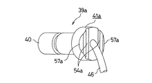
一方、前記センサユニット39aを構成する鍔部41aの基端面には、互いに平行な抑え溝54a、54aを、ハーネス46を挟む状態で形成している。これら両抑え溝54a、54aには、それぞれ上記結合ばね47c、47cの抑え部50a、50aを、がたつきなく係合自在である。又、上記鍔部41aの基端面の直径方向反対位置で上記各抑え溝54a、54aよりも外周縁寄り部分には、それぞれ傾斜面57a、57aを形成して、上記鍔部41aの厚さを、上記各抑え溝54a、54aからこの鍔部41aの端縁に向かう程小さくしている。
【0047】
上述の様なセンサユニット39aを、前記係止筒44cの内側に保持固定するには、予め上記1対の結合ばね47c、47cの枢支部73、73をそれぞれ上記1組ずつの枢支片72、72に係合させておく。この係合作業は、広い空間で容易に行なえる。そして、上記1対の結合ばね47c、47cを上記係止筒44cの側方に揺動変位させ、これら各結合ばね47c、47cの抑え部50a、50aを上記係止筒44cの開口部から退避させた状態で、上記センサユニット39aの挿入部40を上記係止筒44cの内側並びに挿入孔38内に挿入し、上記鍔部41aを上記係止筒44cの先端面に当接させる。この状態で、上記センサユニット39aを構成する挿入部40の先端面に設けた検出部と前記エンコーダ3を構成する円輪部16の内側面との間に、所望寸法の微小隙間が存在する様に、各部の寸法を規制している。次いで、上記1対の結合ばね47c、47cを、それぞれの抑え部50a、50aを上記鍔部41aに向け近づける方向に揺動変位させて、これら各抑え部50a、50aと、上記鍔部41aの基端面に形成した1対の抑え溝54a、54aとを係合させる。この際、上記各抑え部50a、50aと上記各傾斜面57a、57aとの係合に基づいて、前記各弾性脚部74、74が弾性的に伸びる。そして、上記各抑え部50a、50aと抑え溝54a、54aとが整合した状態では、上記各各弾性脚部74、74の全長が弾性的に縮まり、上記各抑え部50a、50aと抑え溝54a、54aとが係合したままの状態となる。
【0048】
又、上記カバー18dから上記センサユニット39aを取り外す際には、上記装着作業時とは反対に、上記各結合ばね47c、47cを、上記係止筒44cの側方に揺動変位させ、これら各結合ばね47c、47cの抑え部50a、50aを上記各抑え溝54a、54aから外す。この様にして上記各抑え部50a、50aを上記各抑え溝54a、54aから外すと共に、これら各抑え部50a、50aを上記係止筒44cの開口部から退避させてから、上記センサユニット39aの挿入部40を上記係止筒44cの内側並びに挿入孔38内から抜き取る。以上に述べた通り構成し作用する本例の場合も、上記センサユニット39bを、上記カバー18dに着脱する作業に要する手間を軽減して、回転速度検出装置付背面組み合わせ型転がり軸受ユニット自体のコスト、並びに修理に要するコストの低減を図れる。
【0049】
尚、本例の場合には、ハブ2aと共に回転輪を構成する内輪7aの内端部に、前述の図59に示した従来構造に組み込んだものと同様のエンコーダ3を外嵌固定している。特に、本例の構造の場合には、上記内輪7aの内端部で第二の内輪軌道8bから軸方向に外れた部分に、小径の段部69を、全周に亙り上記内輪7aと同心に形成している。そして、この段部69に、上記エンコーダ3を構成する円筒部15を外嵌固定している。又、上記エンコーダ3の被検出面は、上記第二の内輪軌道8b上を転動する複数の転動体9、9のピッチ円の直径d 9 よりも直径が小さい部分と直径が大きい部分とを有する。又、上記エンコーダ3の被検出面は、上記第二の内輪軌道8bの最大直径部の直径d 8b よりも直径が小さい部分と直径が大きい部分とを有する。上記段部69を形成する理由は、カバー18dの直径を大きくする事なく、上記エンコーダ3とセンサユニット39aを構成する挿入部40の先端面とを対向させる為である。
【0050】
即ち、転がり軸受ユニットに大きなスラスト荷重或はモーメント荷重が加わった場合にも、転動体9、9が上記内輪7aの外周面に設けた内輪軌道8から外れない様にする為、上記内輪7aの内端部で第二の内輪軌道8bから軸方向に外れた部分には、十分に大きな外径を有する肩部70を形成する必要がある。一方、上記内輪7aを含む回転輪の回転速度を検出する為には、上記エンコーダ3を構成する円輪部16と挿入部40の先端面とを対向させる必要がある。上記エンコーダを構成する円筒部15を上記肩部70自体に外嵌すると、上記円輪部16の直径が必要以上に大きくなり、この円輪部16と対向するセンサユニット39aを支持固定するカバー18dの直径も必要以上に大きくなる場合がある。これに対して、上述の様な段部69を設け、この段部69に上記エンコーダ3を外嵌固定すれば、このエンコーダ3やカバー18dの直径が必要以上に大きくなる事を防止できて、小型の回転速度検出装置付背面組み合わせ型転がり軸受ユニットの実現に寄与できる。この様な構造は、本例に限らず、他の実施の形態にも適用できる事は勿論である。
【0051】
更に、図示の例の場合には、前記ハブ2aの内端部に円筒部71を形成し、この円筒部71の先端部で上記内輪7aの内端面から突出した部分を直径方向外方にかしめ広げる事により、上記内輪7aを上記ハブ2aに対し結合固定している。この様な構造を採用すれば、前述の図59に示した従来構造、或は図1に示した実施の形態の第1例の様に、ナットにより内輪とハブとを結合固定する構造に比べて、部品点数の減少と組立の手間の軽減とにより、コスト削減を図れる。尚、上記円筒部71の先端部を直径方向外方にかしめ広げる際、上記内輪7aの一部には直径方向外方に向いた力が加わる。この荷重が大きい場合、上記第二の内輪軌道8bの直径が変化し、転動体9、9に付与した予圧が変化する事が考えられる。但し、本例の場合には、上記かしめ広げに伴う力は、上記段部69が受け、上記第二の内輪軌道8b部分にはこの力は殆ど加わらない。従って、上記予圧が変化する事は殆どない。この様な構造も、他の実施の形態にも適用できる。
【0052】
尚、本例の場合には、エンコーダ3として磁性材製で円輪部16に複数のスリット状の透孔17を形成したものを使用した例に就いて説明した。従って、前記センサユニット39aに組み込むセンサの構造も、エンコーダとして永久磁石を使用するものとは異ならせている。尚、上記センサにMR素子を使用する場合には、このMR素子の配列方向を、上記透孔17の長手方向(上記円輪部16の直径方向)との関係で規制する必要がある。本例の場合には、前記各抑え部50a、50aと前記各抑え溝54a、54aとの係合により、前記カバー18dに対する上記センサユニット39aの方向を規制できるので、特に別途位置決め手段を設けなくても、上記MR素子の配列方向を上記透孔17の長手方向との関係で規制できる。
【0053】
次に、図17〜20は、本発明の実施の形態の第5例を示している。本例の場合には、カバー18eに設けた係止筒44dの一部で直径方向反対側位置に、それぞれがスリット状で上記係止筒44dの内外両周面同士を連通させる1対の係止孔75、75を形成している。一方、センサユニット39bを構成する挿入部40の一部で直径方向反対側位置には係止溝76、76を、それぞれ設けている。そして、上記センサユニット39bの基端部(図17、19の右端部)に設けた鍔部41bと上記係止筒44dの先端面とを当接させた状態で、上記各係止孔75、75と係止溝76、76とが、軸方向に亙り少しだけずれた状態で、互いにほぼ整合する様にしている。即ち、この状態では、上記各係止溝76、76が上記各係止孔75、75よりも少しだけ上記係止筒44dの先端面寄り(図17〜18の右寄り)に存在する様に、各部の寸法を規制している。
【0054】
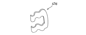
上述の様なカバー18eに形成した係止筒44dにセンサユニット39bを結合固定する為の結合ばね47dは、図20に示す様な、全体がU字形、コ字形、若しくは欠円環状で波形の板ばねとしている。上記係止筒44dにセンサユニット39bを結合固定する際には、先ず、上記センサユニット39bを構成する挿入部40を上記係止筒44dに挿入し、この係止筒44dの先端面と上記鍔部41bとを当接させると共に、上記各係止孔75、75と係止溝76、76とを部分的に整合させる。そして、この状態で、これら各係止孔75、75と係止溝76、76との間に上記結合ばね47dを、この結合ばね47dの厚さ寸法を弾性的に縮めつつ挿入する。これら各係止孔75、75と係止溝76、76との間に挿入された上記結合ばね47dは、上記各係止孔75、75の先端側内側面77、77と、上記各係止溝76、76の先端側内側面78、78との間で突っ張り、上記センサユニット39bの挿入部40に、上記係止筒44dの内側に引き込む方向の弾力を付与する。この様な本例の構造の場合も、センサユニット39bを、上記カバー18eに着脱する作業に要する手間を軽減して、回転速度検出装置付背面組み合わせ型転がり軸受ユニット自体のコスト、並びに修理に要するコストの低減を図れる。
【0055】
次に、図21〜24は、本発明の実施の形態の第6例を示している。上述した各例が何れも、非駆動輪(FF車の後輪、FR車の前輪)を支持する為の転がり軸受ユニットを対象としていたのに対して、本例並びに後述する第7例の場合には、駆動輪(FF車の前輪、FR車の後輪、4WD車の全輪)を支持する為の転がり軸受ユニットを対象としている。この為に本例の場合には、ハブ2bとして、内側に等速ジョイントの軸を挿通自在なスプライン孔79を有する円筒状のものを使用している。又、上記等速ジョイントとの干渉を防止する為、カバー18fを円環状に形成し、センサユニット39cを、このカバー18fの直径方向に配置している。
【0056】
この為に本例の場合には、上記カバー18fの外面の一部に庇状の取付フランジ部80を形成し、この取付フランジ部80に挿入孔38aを、上記カバー18fの直径方向に亙り形成している。本例の場合、この挿入孔38aの断面形状は四角形としている。又、上記取付フランジ部80の先端部内周側面には係止溝48aを、上記取付フランジ80の基端部には係止孔81を、それぞれ上記カバー18fの円周方向に亙り形成している。又、上記センサユニット39cは、上記挿入孔38a内にがたつきなく挿入自在とすべく、断面形状を四角形とした挿入部40aと、この挿入部40aの基端部に設けた外向フランジ状の鍔部41とを備える。そして、この鍔部41の基端面に、前述した第1例の場合と同様の、抑え溝54及び傾斜面57を形成している。エンコーダ3aを構成する永久磁石35の内側面と対向する検出部は、上記挿入部40aの先端部外側面(図21の下端部左側面)に設けている。
【0057】
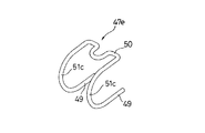
一方、上記取付フランジ部80に上記センサユニット39cを結合固定する為の結合ばね47eは、1対の係止脚部49、49と、これら1対の係止脚部49、49同士の間に掛け渡す様にして設けた抑え部50とを備える。この抑え部50の両端部と上記1対の係止脚部49、49の一端部とは、湾曲した連結部51c、51cにより連結している。これら各連結部51c、51cは、自由状態で上記抑え部50の両端部と上記1対の係止脚部49、49とを近づけ合う方向の弾力を有する。又、上記各係止脚部49、49は、それぞれの先端部まで直線状に形成している。
【0058】
上述の様に構成する取付フランジ部80に上記センサユニット39cを、やはり上述した様に構成する結合ばね47eを使用して保持固定するには、この結合ばね47eを外した状態で、上記センサユニット39cの挿入部40aを上記取付フランジ部80の挿入孔38a内に、直径方向外方から内方に挿入する。そして、上記鍔部41を上記取付フランジ部80の外周側面に当接させる。次いで、上記結合ばね47eを構成する1対の係止脚部49、49と抑え部50との間隔を広げつつ、これら係止脚部49、49を前記係止溝48a及び係止孔81に係合若しくは挿入すると共に、抑え部50を上記鍔部41の基端面に乗り上げさせる。そして、この抑え部50と、上記鍔部41の基端面に形成した抑え溝54とを係合させる。
【0059】
この様な本例の構造の場合も、上記センサユニット39cを、上記カバー18fに着脱する作業に要する手間を軽減して、回転速度検出装置付背面組み合わせ型転がり軸受ユニット自体のコスト、並びに修理に要するコストの低減を図れる。尚、本例の構造の場合には、外輪1の内端部内周面にシールリング82を内嵌固定し、このシールリング82と前記エンコーダ3aを構成する支持環34とにより組み合わせシールリングを構成し、転動体9、9を設置した空間43内への異物進入防止を図っている。
【0060】
次に、図25〜30は、本発明の実施の形態の第7例を示している。本例の場合には、カバー18gを構成する合成樹脂製の本体28aを、全周に亙って断面L字形に形成している。そして、このカバー18gを構成する円筒壁部36aの一部を厚肉にして、この厚肉部分に挿入孔38bを、上記カバー18gの直径方向に亙り形成している。本例の場合、この挿入孔38b、及び、センサユニット39dを構成してこの挿入孔38b内に挿入される挿入部40bの断面形状は、それぞれ円形としている。
【0061】
この様に、挿入孔38b及び挿入部40bの断面形状を円形とする代わりに、本例の場合には、上記センサユニット39dの基端部に設けた鍔部41cと、上記カバー18gの円筒壁部36aの中間部に形成した段部87との係合により、上記センサユニット39dの回り止めを図っている。即ち、上記鍔部41cの形状を略D字形にして、この鍔部41cの外周縁の一部に平坦面83を形成すると共に、上記挿入部40bを上記挿入孔38b内に挿入した状態で、上記段部87と上記平坦面83とを密接若しくは近接させている。本例の場合、この様な平坦面83を設ける事により、上記センサユニット39dの回り止めを図ると同時に、このセンサユニット39dを設置する為に必要な軸方向(図25の左右方向)寸法の節減図っている。又、上述の様な鍔部41cの基端面には、前述した第1〜3例及び上述した第6例の場合と同様の抑え溝54及び傾斜面57を形成している。上記センサユニット39dを上記カバー18gに結合固定した状態では、次述する結合ばね47fの抑え部50bが上記抑え溝54と係合し、上記鍔部41cを上記円筒壁部36aの外周面に抑え付ける。
【0062】
本例に使用する結合ばね47fは、中央部に設けた上記抑え部50bと、両端部に設けた枢軸状の係止脚部49a、49aとを、略四分円状の連結部51d、51dにより連結して成る。上記各係止脚部49a、49aは、上記結合ばね47fの両端部である上記各連結部51d、51dの端部から、互いに逆方向に折れ曲がったもので、互いに同軸上に配置している。この様な上記各係止脚部49a、49aを枢支すべく、上記カバー18gの段部87の外面の一部で、上記挿入孔38bを中心として直径方向反対側2個所位置には、それぞれ鉤状の枢支部84を形成している。上記結合ばね47fの自由状態での、上記各係止脚部49a、49aの先端同士の間隔D49a は、上記1対の枢支部84同士の間隔D84(図示せず)よりも十分に大きく(D49a >D84)している。又、これら各枢支部84は、上記挿入孔38bと反対側のみが開口している。従って上記各係止脚部49a、49aを上記各枢支部84に係止した状態では、これら各係止脚部49a、49aが上記挿入孔38b側にずれる事はない。尚、上記各係止脚部49a、49aを枢支する為の枢支部は、図示の様な鉤形に限らず、門形、孔形等にする事もできる。
【0063】
又、上記カバー18gの底板部37aの一部外面で上記挿入孔38bに整合する部分には、上記抑え部50bを係止しておく為の係止フック85を、上記カバー18gを合成樹脂により射出成形する際、一体に形成している。上記結合ばね47fは、転がり軸受ユニットを造るメーカーで、図29に示した状態に、上記カバー18gに装着しておく。即ち、上記各係止脚部49a、49aを上記各枢支部84に係止すると共に、上記抑え部50bを係止フック85に係止しておく。この状態で上記抑え部50bは、上記挿入孔38bの開口部から退避して、前記センサユニット39dを構成する挿入部40bをこの挿入孔38b内に挿入する事に対する妨げとはならない。又、この様な状態で、上記結合ばね47fは、上記カバー18gの外周面から直径方向外方に突出する事がない。この為、この結合ばね47fが、上記カバー18gを図示しないナックルの支持孔に挿入しつつ、回転速度検出装置付背面組み合わせ型転がり軸受ユニットを自動車の懸架装置に支持する作業の妨げとなる事もない。尚、上記係止フック85の一部には傾斜縁86を形成して、上記抑え部50bをこの係止フック85に係止する作業を容易に行なえる様にしている。尚、図示の例では、上記係止フック85と上記結合ばね47fのU字形の湾曲部52aとを係合させる様にしている。但し、係止フックには、上記湾曲部52aを挟む状態で設けた、1対の直線部53a、53aを係合させる様にする事も可能である。この場合、係止フックを、間隔をあけて1対設ける。
【0064】
前述の様に構成するカバー18gを構成する円筒壁部36aに上記センサユニット39dを、やはり上述した様に構成する結合ばね47fを使用して保持固定する際には、この結合ばね47fの抑え部50bを図29に示す様に、上記挿入孔38bから退避させておく。そして、この状態で、上記センサユニット39dの挿入部40bを上記円筒壁部36aに形成した挿入孔38bに、直径方向外方から内方に挿通する。そして、前記鍔部41cを上記円筒壁部36aの厚肉部分の外周面に当接させると共に、前記段部87と前記平坦面83とを密接若しくは近接させる。次いで、上記結合ばね47fの抑え部50bを上記係止フック85から外し、この結合ばね47fを上記各係止脚部49a、49aを中心として、図29の反時計方向に揺動させ、上記抑え部50bを前記鍔部41cの基端面に乗り上げさせる。そして、この抑え部50bと、上記鍔部41cの基端面に形成した抑え溝54とを係合させる。
【0065】
この様な本例の構造の場合も、上記センサユニット39dを、上記カバー18gに着脱する作業に要する手間を軽減して、回転速度検出装置付背面組み合わせ型転がり軸受ユニット自体のコスト、並びに修理に要するコストの低減を図れる。尚、本例の構造の場合には、上記カバー18gを構成する円輪状の底板部37aの内周縁にシールリング82aを構成する芯金88の外径側半部を包埋し、この芯金88の内周縁部に全周に亙って添着したシールリップ89の先端縁を、等速ジョイント90の外周面に摺接させている。本例の場合には、このシールリップ89が、転動体9、9を設置した空間43内への異物進入防止を図っている。従って、エンコーダ3a部分にも、異物が入り込む事はない。
【0066】
次に、図31〜32は、本発明の実施の形態の第8例を示している。本例の場合には、結合ばね47gの各係止脚部49b、49bを枢支する為の枢支部84aを、カバー18hの段部87の直径方向反対側2個所位置に設けた突出部91により構成している。そして、これら各突出部91同士の互いに反対側の面に、上記カバー18hの内周面にまで貫通しない(有底の)凹孔92を、互いに同心に設けている。又、本例に使用する上記結合ばね47bは、図32に示す様に、抑え部50bの両端から連続した連結部51e、51eの先端部に設けた1対の係止脚部49b、49b同士を、互いに近づく方向に折り曲げて成る。これら1対の係止脚部49b、49bは、互いに同軸上に配置している。そして、上記各枢支部84aの凹孔92に上記各係止脚部49b、49bを係止し、上記カバー18hに対して上記結合ばね47fを、上記1対の係止脚部49b、49bを中心とする揺動自在に支持する。上記各係止脚部49b、49bが上記各枢支部84aから外れない様にする為、上記結合ばね47fの自由状態での、上記各係止脚部49b、49bの先端同士の間隔D49b は、上記1対の枢支部84a同士の間隔D84a (図示せず)よりも十分に小さく(D49b <D84a )している。又、上記結合ばね47fの連結部51e、51eは、短い全長でも必要な弾力を持たせる為、蛇行した形状としている。その他の構成及び作用に就いては、上述した第7例と同様である為、同等部分には同一符号を付して、重複する図示並びに説明は省略する。
【0067】
次に、図33〜39は、発明の実施の形態の第9例を示している。静止輪である外輪1の内端(図33の右端)開口部は、カバー18iにより塞いでいる。このカバー18iは、前述した第1例の構造に組み込んだカバー18aと同様に、合成樹脂を射出成形して成る有底円筒状の本体28bと、この本体28bの開口部に結合した嵌合筒29とから成る。又、ハブ2aと共に回転輪を構成する内輪7aは、前述の図12に示した第4例と同様に、このハブ2aの内端部に外嵌し、更にこのハブ2aの一部を直径方向外方にかしめ広げる事により、このハブ2aに対し固定している。この様な内輪7aの内端部(図33の右端部)に形成した段部69には、前述の図59〜60に示した従来構造の場合と同様のエンコーダ3を外嵌固定している。
【0068】
又、上記カバー18iを構成する本体28bの底板部37bの一部で、上記エンコーダ3を構成する円輪部16の内側面と対向する部分には挿入孔38を、上記底板部37bを貫通させる状態で、上記外輪1の軸方向に亙り形成している。又、上記底板部37bの外面(上記カバー18iにより塞ぐべき、転動体9、9を設置した空間43と反対側の側面で、図33の右側面)の一部で、上記挿入孔38の開口周囲部分には、係止筒44eを設けて、上記挿入孔38の内周面と共に、単一円筒面を構成している。そして、これら挿入孔38及び係止筒44e内に、前述の第1例に組み込んだセンサユニット39(図1、3)と同様のセンサユニット39eの先端寄り部分を挿入している。
【0069】
一方、上記係止筒44eの基端寄り(図34、37、38、39の左端寄り)部分で、この係止筒44eの直径方向ほぼ反対側位置には1対の枢支孔93を、互いに同心に形成している。これら各枢支孔93は、上記係止筒44eの内周面にまでは貫通させていない。この理由は、これら各枢支孔93を通じて、上記係止筒44e内に異物が入り込むのを防止する為である。更に、前記底板部37bの外面で上記係止筒44eの外周面の近傍位置には、抜け止め手段を構成する1対のストッパプレート94を、前記カバー18iと一体に設けている。尚、これら両ストッパプレート94、94の形成位置は、上記各枢支孔93の延長上から外れた位置としている。図示の例では、これら両枢支孔93を、上記係止筒44eの直径方向反対位置よりも少しカバー18iの直径方向外方(図34、37、38、39の上方)に少しだけずれた位置に形成している。これに対して、上記両ストッパプレート94を、上記係止筒44eの直径方向反対位置に設けている。又、上記両ストッパプレート94の互いに対向する側の端縁と、上記係止筒44eの外周面との間には、次述する結合ばね95の基端寄り部分を挿入自在な隙間を設けている。
【0070】
上記カバー18iに対して上記センサユニット39eを結合する為の結合ばね95の両端部には1対の枢支部96、96を、互いに同心に、それぞれの先端面同士を互いに対向させた状態で設けている。又、上記結合ばね95の中間部には、前記センサユニット39eに設けた鍔部41dを、上記係止筒44eの開口端面に向け押圧する為の抑え部97を設けている。この抑え部97は、上記結合ばね95を構成する線材を曲げ形成して成り、両端に設けた互いに同心の直線部98、98と、これら両直線部98、98同士の間に存在する、略半円弧形の湾曲部99とを備える。又、この湾曲部99の中間部には、上記枢支部96、96とは反対側に向け折れ曲がった摘み部100を設けている。この摘み部100は、後述するカバー18iへのセンサユニット39eの着脱作業の為、上記抑え部97を上記鍔部41dに対して進退させる際に、手指を掛ける為の手掛かりとして利用する。この為に上記摘み部100の幅W100 (図36)は、手の親指を掛け易い大きさ(例えば15mm以下)に規制している。更に、上記抑え部97の両端部と上記各枢支部96、96とは、それぞれ弾性変形部101、101により互いに連続させている。これら両弾性変形部101、101は、上記線材を曲げる事により、「く」字形或は円弧形に形成したもので、全長を縮める方向の弾性を有する。
【0071】
一方、前記センサユニット39eに設けた上記鍔部41dの基端面(挿入部40cと反対側の面で、図33、34、39の右端面)には、上記結合ばね95の抑え部97をがたつきなく係合させる為、前述した第1例の場合と同様の抑え溝54と傾斜面57とを形成している。
【0072】
それぞれが上述の様に構成される各部材を組み合わせて、本例の回転速度検出装置付背面組み合わせ型転がり軸受ユニットを構成すべく、上記センサユニット39eを前記カバー18iに装着する作業は、次の様にして行なう。先ず、これらセンサユニット39eとカバー18iとを組み合わせるのに先立って、このカバー18iに設けた係止筒44eに、上記結合ばね95を装着しておく。この装着作業は、先ず、図37に示す様に、結合ばね95全体を、上記カバー18iの直径方向外方寄りで前記両ストッパプレート94よりも直径方向外側部分に位置させた状態で行なう。この状態で、前記1対の枢支部96、96同士の間隔を弾性的に広げて、これら両枢支部96、96と前記両枢支孔93とを整合させ、これら両枢支部96、96を両枢支孔93内に挿入する。この際、上記両ストッパプレート94は、上記両枢支部96、96を両枢支孔93内に挿入する作業の妨げとはならない。
【0073】
上述の様にして、上記結合ばね95の基端部(上記両枢支部96、96を設置した端部)を上記係止筒44eに枢支したならば、上記結合ばね95を上記両枢支部96、96を中心に、図38に示す状態にまで揺動させる。即ち、上記結合ばね95を構成する弾性変形部101、101の一部が上記カバー18iを構成する本体28bの底板部37bの外面に当たるまで上記結合ばね95を揺動させ、上記両弾性変形部101、101の基端寄り部分を、上記係止筒44eの外周面と上記両ストッパプレート94の端縁との間に位置させる。この状態で、上記抑え部97は、上記係止筒44eの先端開口周囲部分から完全に退避して、次述するセンサユニット39eとカバー18iとの組み合わせ作業時に、上記センサユニット39eの一部と上記抑え部97とが干渉する事を防止する。尚、上記係止筒44eは、上記カバー18iの上端寄り部分に設ける為、結合ばね95は、重力により図38に示した状態で安定する。この状態では、上記結合ばね95が、ナックルの一部と干渉する事はなく、上記カバー18i及び結合ばね95を装着した外輪1を、このナックルに設けた取付孔に挿入可能になる。従って、上記カバー18iに結合ばね95を装着した状態で自動車の組立メーカーに納入すれば、この組立メーカーで、上記結合ばね95をカバー18iに装着する作業を省略できる。
【0074】
上記カバー18iに上記センサユニット39eを結合固定するには、上述の様にして上記結合ばね95を上記係止筒44eに装着し、この結合ばね95を図38に示した位置にまで揺動させた状態で、上記センサユニット39eの先端寄り部分である挿入部40cを、上記係止筒44e及び前記挿入孔38に挿入する。そして、前記鍔部41dを上記係止筒44eの先端面に当接させる。この状態で、上記センサユニット39eを構成する挿入部40cの先端面に設けた検知部24と前記エンコーダ3を構成する円輪部16の内側面との間に、所望の厚さ寸法(例えば0.5mm程度)の微小隙間が存在する。次いで、上記結合ばね95を、上記1対の枢支部96、96を中心に、上記抑え部97を上記鍔部41dに近づける方向に揺動させる。そして、上記抑え部97を、図39に示す状態を経て、図33〜34に示す様に、上記鍔部41dの基端面に乗り上げさせ、上記鍔部41dを上記係止筒44eの先端面に押圧する。この状態で、上記抑え部97が、上記鍔部41dの基端面に形成した抑え溝54に係合する。
【0075】
上述の様に、上記結合ばね95の抑え部97を上記鍔部41dの基端面に乗り上げさせる作業は、前記摘み部100を手指により押圧する事により行なう。この摘み部100を上記鍔部41dに向け押圧する事に伴い、上記抑え部97の両端部に設けた直線部98、98が、上記鍔部41dに形成した前記傾斜面57に乗り上げる。この状態から更に上記摘み部100を押圧する作業を継続すれば、上記抑え部97が上記鍔部41dの基端面に形成した抑え溝54に係合する。この様に抑え部97と抑え溝54とが係合した状態で、前記1対の弾性変形部101、101は、弾性的に全長が伸ばされた状態となる。従って、上記抑え部97は、これら1対の弾性変形部101、101の弾性復元力に基づき、上記鍔部41dを上記係止筒44eの先端面に向け弾性的に押圧する。尚、この作業を容易に行なえる様にすべく、上記結合ばね95を自由状態のまま上記各枢支部96、96を中心に回動させた場合に、上記各直線部98、98が上記傾斜面57に当接する様に、上記結合ばね95の寸法を規制している。又、上述の様に、結合ばね95を係止筒44eに対して揺動変位させる際に、上記各弾性変形部101、101とこの係止筒44eの外周面及び上記鍔部41dの外周縁とが干渉しない様に、これら1対の弾性変形部101、101の間隔は、上記係止筒44e及び鍔部41dの外径よりも少し大きくしておく。
【0076】
上述の様にして、上記抑え部97が抑え溝54に係合した状態では、上記結合ばね95が上記鍔部41dを上記係止筒44eの先端面に向け、十分に大きな力で押し付けて、上記センサユニット39eを上記カバー18iに結合する。又、この状態では、上記各弾性変形部101、101の一部で前記各枢支部96、96の近傍部分が、前記1対のストッパプレート94の端縁に当接若しくは近接する。従って、上記各弾性変形部101、101の基端部同士の間隔が広がる方向に弾性変形する事は殆どなく、上記各枢支部96、96が前記各枢支孔93から抜け出る事はなくなる。この結果、走行時の飛び石等が上記結合ばね95に勢い良く衝突した場合等、上記各弾性変形部101、101に外力が作用した場合でも、上記各枢支部96、96が上記各枢支孔93から抜け出る事はなくなり、上記センサユニット39eが上記カバー18iとの結合部から不用意に外れる事がなくなる。
【0077】
上記センサユニット39eを上記カバー18iから取り外す際には、上述した装着作業の場合とは逆に、先ず、前記摘み部100に手指を掛けて、上記結合ばね95の抑え部97を上記鍔部41dの基端面から退避させる。この様にして上記抑え部97を鍔部41dから退避させた後、上記センサユニット39eの挿入部40cを、前記挿入孔38及び係止筒44eの内側から抜き取る。
【0078】
次に、図40は、発明の実施の形態の第10例を示している。本例の場合には、ストッパプレート94、94の互いに対向する端縁で、カバー18iを構成する本体28bの底板部37bの外面(図40の上面)から少し離れた部分に、それぞれ係止突起102、102を形成している。そして、これら各係止突起102、102の先端同士の間隔D102 を、自由状態に於ける結合ばね95の弾性変形部101、101の外側縁同士の間隔D101 よりも小さく(D102 <D101 )している。従って、本例の場合には、前述の図38に示す様に、抑え部97を係止筒44eの先端開口部分から退避する方向に揺動させた状態で、上記カバー18iの姿勢に関係なく、上記結合ばね95とカバー18iとの位置関係を一定にできる。この為、カバー18iを装着した転がり軸受ユニットを組み立てたメーカーから、センサユニットを装着する自動車の組立メーカーに納入する過程で、上記結合ばね95の位置関係がずれ動かない様にして、自動車の組立メーカーでの組立作業の能率化を図れる。
【0079】
次に、図41は、発明の実施の形態の第11例を示している。本例の場合には、結合ばね95aを構成する線材の径を太くしても必要とする弾性を得られる様に、1対の弾性変形部101a、101aの全長を長くして、これら各弾性変形部101a、101aの曲がり量を多くしている。即ち、本の回転速度検出装置付背面組み合わせ型転がり軸受ユニットに組み付ける結合ばね95aは、泥水や融雪剤等が付着する可能性が高い為、錆び易い状況にある。ステンレスのばね鋼により造る場合には、特に上記線材の径を太くしなくても必要とする耐久性を確保する事は容易であるが、比較的安価な非ステンレス鋼である、通常のばね鋼を使用した場合には、表面に亜鉛メッキやクロムメッキを施したとしても、必要とする耐久性を確保する為には、上記線材の径を太くする必要が生じる。これに対し、この径を太くすると、結合ばね95aの剛性が高く(ばね常数が大きく)なり過ぎて、抑え部97を鍔部41d(図39参照)に乗り上げさせる事が困難になる。これらの事を考慮すると、上記結合ばね95aを構成する線材の径は1〜2mm程度が適当である。但し、この径を2mm程度にした場合には、前述の図35に示した様な結合ばね95の形状では、この結合ばね95の剛性が高くなり過ぎる。そこで、上記径を太くした場合には、本例の様に、1対の弾性変形部101a、101aの全長を長くして曲がり量を多くし、必要とする弾性を確保する。
【0080】
尚、前述した第9〜11例の回転速度検出装置自体の構造に関しては、パッシブ型磁気センサを使用したものに限らず、アクティブ型磁気センサを使用するもの採用する事もできる。尚、アクティブ型磁気センサを用いたものは、センサユニット全体を小型且つ軽量にできる。従って、慣性質量が小さく、自動車走行に伴う振動による運動エネルギも小さくて済む。この結果、結合ばね95に要求される抑え荷重を小さくすることができて、上述の様な細い(1〜2mm程度)線材を用いた結合ばね95の使用が可能になる。
【0081】
次に、図46〜50は、発明の実施の形態の第12例を示している。本例は、前述した第11例の構造に於いて新たに生じる問題を解消すべく考えたものである。即ち、前述した第11例で示した結合ばね95aは、錆び易い状況にある結合ばね95aの耐久性を確保する為、線材の径を太くする代りに、この結合ばね95aを構成する1対の弾性変形部101a、101aの全長を長くして曲がり量を多くしている。
【0082】
又、上記結合ばね95aを構成する線材の径を太くしたり、この線材の材料を変更したりする等により剛性を上げると共に、上記1対の弾性変形部101a、101aの全長を長くすれば、上記結合ばね95aと、この結合ばね95aと係合するカバー18i又はセンサユニット39eとの係合部分に寸法誤差があった場合に、この寸法誤差を有効に吸収する事ができる。即ち、結合ばね95aを、剛性の高い材料により造ると共に弾性変形部101a、101aの全長を長くすれば、この結合ばね95aにより上記センサユニット39eを抑え付ける荷重を適正範囲に保持すると共に、この結合ばね95aに加わる応力を許容値内に収めつつ、上記寸法誤差を吸収できる。これに対して、上記1対の弾性変形部101a、101aの全長を短くしたまま、上記線材の剛性を下げて所定の弾性変形量を確保する事により、上記寸法誤差を吸収する事もできるが、上記係合部分の寸法誤差に拘らず、上記結合ばね95aにより上記センサユニット95aを抑え付ける荷重を適正に保持したり、この結合ばね95aに加わる応力を許容値内に収める事が難しくなる。従って、この様な理由からも、上記1対の弾性変形部101a、101aの全長を長くする事が好ましい場合が生じる。
【0083】
ところが、単にこれら1対の弾性変形部101a、101aを長くすると、図42〜43に示す様に、センサユニット95aを係止筒44eに抜き差しすべく、1対の枢支孔93に枢支した1対の枢支部96を中心として、上記結合ばね95aを揺動させても、上記1対の弾性変形部101a、101aの一部が上記カバー18jの底板部37bの側面に当接して、この結合ばね95aの揺動が制限され、この結合ばね95の抑え部97が上記係止筒44eの開口部から退避し切れない場合が生じる。この様に抑え部97が係止筒44eの開口部から退避し切れなかった場合に、この抑え部97が、上記センサユニット95aを上記カバー18jに着脱する妨げとなる。
【0084】
一方、この様な弊害をなくすべく、図44〜45に示す様に、枢支孔93とカバー18kの底板部37bの側面との間の軸方向距離L93を十分に確保して、上記抑え部97が係止筒44fの開口部から退避し切るまで、上記結合ばね95aを揺動自在とする構造も考えられる。但し、この様な構造では、上記枢支孔93を設けた係止筒44fの軸方向長さが大きくなり、回転速度検出装置付背面組み合わせ型転がり軸受ユニットの小型化を図りにくくなる。
図46〜50に示した第12例の回転速度検出装置付背面組み合わせ型転がり軸受ユニットは、上述の様な不都合を解消すべく、結合ばねの全長を十分に長くしても、カバーに対するセンサユニットの着脱性を良好なままにできる構造を実現すべく考えたものである。
【0085】
本例の回転速度検出装置付背面組み合わせ型転がり軸受ユニットの特徴は、結合ばね95bの全長を十分に長くしても、カバー18jに対するセンサユニット39eの着脱性を良好なままにできる構造にある。その他の部分の構成及び作用に就いては、前述した図33〜39、41に示した第9、11例と同様である為、同等部分に関する説明並びに図示は、省略若しくは簡略にする。尚、本例では第9、11例の様に、結合ばね95aの枢支部96がカバー18jに設けた枢支孔93から抜け出すのを防止する為のストッパプレート94(図34、37、38、39)は設けていないが、必要とすれば設ける事もできる。
【0086】
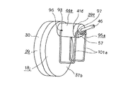
外輪1(図33参照)の内端開口部を塞ぐカバー18jの底板部37bの側面の一部には、軸方向(図46、47の左右方向)に突出する状態で係止筒44eを設けている。そして、この係止筒44eの外周面で直径方向ほぼ反対側2箇所位置に、内周面にまで貫通しない1対の枢支孔93を互いに同心に設け、これら各枢支孔93に、弾性部材である結合ばね95bの両端部に設けた1対の枢支部96を枢支自在としている。上記結合ばね95aは、図48〜50に示す様に、両端部に互いに同心である1対の枢支部96、96を、中間部に上記センサユニット39eの基端部に設けた鍔部41dを上記係止筒44eの開口周縁部に押圧する抑え部97を、これら1対の枢支部96、96の一端と抑え部97の両端との間に、連結部である1対の弾性変形部101b、101bをそれぞれ設けている。これら1対の弾性変形部101b、101bは、上記枢支部96、96の一端から連続した1対の第一の直線部103、103と、上記抑え部97の両端から連続した1対の第二の直線部104、104と、これら第一、第二の直線部103、104同士を連結する1対の曲線部105、105とから成る。上記1対の弾性変形部101b、101bの全長は、前述した理由、即ち、上記結合ばね95bの耐久性を確保すると共に、この結合ばね95bと係合する各部材との寸法誤差を有効に吸収する為、十分に長くしている。
【0087】
特に、本例の場合には、上記1対の弾性変形部101b、101bを、上記抑え部97が上記センサユニット39eを上記挿入孔38の開口周縁部に押圧した状態で、前記カバー18jの底板部37bに対して、上記各曲線部105、105に向う程この底板部37bから離れる方向に傾斜させている。即ち、上記弾性変形部101b、101b全体を、上記1対の枢支孔93を含み、且つ上記カバー18jの底板部37bの側面と平行な仮想平面β(図47)よりも、上記挿入孔38の開口側(図46、47の右側)に位置させ、且つ、上記枢支孔93から離れる程、上記仮想平面βから離れる方向に傾斜させている。この構成により、センサユニット39eを上記係止筒44eに抜き差しする事に対して、上記抑え部97が妨げとならない状態にまで、上記結合ばね95bを揺動自在としている。この為に、この結合ばね95bの抑え部97を上記センサユニット39eの鍔部41dに係合した状態で、上記各弾性変形部101b、101bを構成する、上記底板部37b寄り部分である第一の直線部103、103と、上記仮想平面βとのなす角度γを、設計的に定まる所定値以上としている。即ち、この角度γは、上記結合ばね95bを上記枢支部96、96を中心として図47の時計方向に揺動させて、上記各弾性変形部101b、101bの一部を上記底板部37bの一部に当接させた場合に、上記抑え部97が、上記係止筒44eの開口部から退避し切って(前記係止筒44eの外周面を延長して得られる仮想空間外に退避させて)、この抑え部97が上記センサユニット39eを上記係止筒44eに抜き差しする作業の妨げとならない角度以上としている。
【0088】
上述の様に構成する本例の回転速度検出装置付背面組み合わせ型転がり軸受ユニットの場合も、前述した各例と同様に、上記センサユニット39eを上記カバー18jに着脱する作業に要する手間を軽減して、回転速度検出装置付背面組み合わせ型転がり軸受ユニット自体のコスト、並びに修理に要するコストの低減を図れる。特に、本例の場合、結合ばね95bを構成する1対の弾性変形部101b、101bを傾斜させている。この為、前記各枢支孔93を上記底板部37bの近くに設けても、上記カバー18jに対してセンサユニット39eを着脱すべく、上記結合ばね95bを、上記弾性変形部101b、101bが上記挿入孔38の開口から遠ざかる方向に揺動させた際に、上記結合ばね95bが揺動できる角度を確保できる。従って、この結合ばね95bに設けた抑え部97が、上記センサユニット39eを上記カバー18jに対して着脱する作業の妨げとはならない。この結果、上記結合ばね95bの耐久性を確保すると共に、この結合ばね95bと係合する各部材との寸法誤差を有効に吸収すべく、この結合ばね95bの全長を十分に長くしても、上記係止筒44eの軸方向長さを徒に大きくする事なく、カバー18jに対するセンサユニット39eの着脱性を良好にしたままにできる。
【0089】
尚、本例の場合、上記結合ばね95bに設けた抑え部97の中間部に、この抑え部97を上記センサユニット39eの鍔部41dに係合させた状態で、この鍔部41dからほぼ垂直な方向に突出する摘み部106を設けている。カバー18jに対してセンサユニット39eを着脱する場合には、この摘み部106を摘む事により、上記結合ばね95bを容易に揺動させる事ができる。尚、この抑え部95bが上記センサユニット39eの抑え溝54に係合した状態では、この結合ばね95bの抑え部97が、上記鍔部41dを上記係止筒44eの端面に向け、十分に大きな力で押し付ける。この為、上記枢支部96と抑え部97の基端部との距離L97に対する、上記枢支部96と摘み部106の先端部との距離L106 の比(レバー比)は、ある程度大きく{例えばレバー比が2以上(L106 /L97≧2)に}する事が、上記結合ばね95bの揺動し易さを確保する点から好ましい。
【0090】
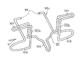
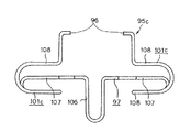
次に、図51〜53は、発明の実施の形態の第13例を示している。本例の場合には、結合ばね95cの両端部に設けた1対の枢支部96、96と中間部に設けた抑え部97とを連結する、1対の弾性変形部101c、101cを、上記結合ばね95cに作用する曲げモーメントが最大となる部分で湾曲させて、これら各弾性変形部101c、101cの全長を長くしている。この様に各弾性変形部101c、101cの所定部位を長くしたのは、次の様な理由による。
【0091】
カスティリアーノの定理(Castigliano's theorem )によると、弾性体に作用する曲げモーメントが大きい断面部分の長さを長くすれば、この弾性体のたわみ量が大きくなる事が知られている。又、弾性体に作用する曲げモーメントを大きくし過ぎると、断面部分に作用する応力が許容応力を越えて、この弾性体が折れる可能性がある。従って、弾性体である、上記結合ばね95cに於いて、作用する曲げモーメントが最大になる部分の長さを長くすれば、より変形し易く、より折れにくい結合ばね95cを得る事ができる。本例の場合、結合ばね95cを揺動させる為に引っ張り荷重Pが働く部分は、結合ばね95cがカバー18j及びセンサユニット39eと係合する部分である、図53に示す点X、Yである。そして、上記結合ばね95cの曲げモーメントが最大に作用する部分は、点Xから最も離れた、距離L95部分、即ち、各弾性変形部101c、101cをそれぞれ構成する、第一の湾曲部107、107部分と第二の湾曲部108、108部分とである。従って、これら各湾曲部107、108の長さを長くする事により、より変形し易く、より折れにくい結合ばね95cを得る事ができる。尚、図示の例の様に、上記第一の湾曲部107、107と第二の湾曲部108、108とを、上記荷重Pの作用線の両側に配置したのは、上記結合ばね95cを上記カバー18jの外周縁よりも直径方向外方に突出させる事なく、上記第一、第二の湾曲部107、108の必要とする長さを確保する為である。その他の構成及び作用は、前述した第12例の場合と同様である。
【0092】
次に、図54〜58は、発明の実施の形態の第14例を示している。回転速度検出装置付背面組み合わせ型転がり軸受ユニットの使用時には、自動車の走行に伴って、センサユニットをカバーに結合支持する結合ばねには、泥水や融雪剤等が付着する可能性が高い。そして、この結合ばねは金属製である為、上述の様に結合ばねに泥水等が付着すると、ばねの材質が、安価な非ステンレス鋼の場合には、早期に錆びる可能性がある。特に、この結合ばねの中間部に設けた抑え部がセンサユニットの鍔部と係合する部分に、上記泥水等が溜り易く、上記部分が特に早期に錆びる可能性がある。
本例の回転速度検出装置付背面組み合わせ型転がり軸受ユニットは、上述の様な事情に鑑みて、結合ばねの材質を安価な非ステンレス鋼とした場合でも、この結合ばねが錆びる事を防止すべく考えたものである。
【0093】
この様に、本例の回転速度検出装置付背面組み合わせ型転がり軸受ユニットの特徴は、結合ばねがセンサユニットと係合する部分を覆う構造にある。その他の部分の構成及び作用に就いては、前述した図46〜50に示した第12例と同様である為、同等部分には同一符号を付して、重複する説明並びに図示を省略若しくは簡略にする。尚、本例では、前述の第9〜10例の様に結合ばね95bの枢支部96がカバー18jに設けた枢支孔93から抜け出すのを防止する為のストッパプレート94(図34、37、38、39、40)は設けていない。但し、次述する被覆部材109との干渉を防止できる限り、上記ストッパプレート94を設けても良い。
【0094】
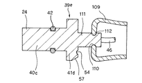
センサユニット39eの基端部中央に設けた円杆状の突部111の中間部外周面に、防水機能を有する被覆部材109を支持している。この被覆部材109は、ゴム、或はハイトレル等の合成樹脂等の弾性材から成る。又、この被覆部材109は、開口部を逆方向にすべく、反転自在な袋状としている。又、この被覆部材109の底部中央には、軸方向に貫通した貫通孔110を設けている。そして、上記突部111の中間部外周面に全周に亙り設けた係止溝112に、上記貫通孔110の内周縁部を係止している。又、上記センサユニット39eの内部に包埋したセンサ(図示せず)と連結したハーネス46は、上記突部111の先端面から導出している。
【0095】
又、上記センサユニット39eを上記カバー18jに対して着脱自在とすべく、上記センサユニット39eの鍔部41dを上記挿入孔38の開口周縁部に押圧する結合ばね95bは、図58に示す様に、両端部に設けた1対の枢支部96、96と、中間部に設けた抑え部97と、これら枢支部96、96と抑え部97とを連結する1対の弾性変形部101b、101bとから成る。これら1対の弾性変形部101b、101bは、上記枢支部96、96の一端から連続した1対の第一の直線部103、103と、上記抑え部97の両端から連続した1対の第三の直線部113、113と、これら1対の第三の直線部113、113の一端から連続した、上記第一の直線部103、103とほぼ平行な第二の直線部104、104と、これら第一、第二の直線部103、104同士を連結する1対の曲線部105、105とから成る。
【0096】
上述の様な被覆部材109を備えた本例の場合、この被覆部材109により、上記結合ばね95bの抑え部97と上記センサユニット39eとが係合する部分を覆っている。上記センサユニット39eをカバー18jに着脱する場合には、図55に示す様に、予め上記センサユニット39eに係止した被覆部材109を上記鍔部41dと反対側に開口させた状態にして、上記センサユニット39eと結合ばね95bとの係合作業の邪魔にならない様にしておく。この状態で、図56に示す様に、上記カバー18jに設けた係止筒44eの内側に上記センサユニット39eの挿入部40cを挿入する。そして、結合ばね95bを、上記係止筒44eに設けた枢支孔93に枢支した枢支部96、96を中心として揺動させて、この結合ばね95bに設けた抑え部97を、上記センサユニット39eの鍔部41dに設けた抑え溝54に係合させる。この部分の構成及び作用は、前述の図46〜50に示した第12例の場合とほぼ同様である。上記抑え部97と抑え溝54とを係合させた後、図54、57に示す様に、上記被覆部材109を反転させて、この被覆部材109の開口部を逆方向に向け、この被覆部材109の開口周縁部を上記係止筒44eの外周面に弾性的に当接させる。この状態で上記被覆部材109が、上記結合ばね95bに設けた抑え部97と上記センサユニット39eとが係合する部分を覆う。
【0097】
上述の様に構成する本例の回転速度検出装置付背面組み合わせ型転がり軸受ユニットによれば、この回転速度検出装置付背面組み合わせ型転がり軸受ユニットの使用時に、上記結合ばね95bと上記センサユニット39eとが係合する部分に、直接外部から泥水等がかかるのを防止して、上記結合ばね95bが錆びる事を防止できる。又、この様に上記結合ばね95bの一部を、被覆部材109により覆った状態では、上記被覆部材109を反転させない限り、上記結合ばね95bを上記センサユニット39eから外す事ができない。従って、前述の様なストッパプレート94(図37〜40)を設けなくても、上記センサユニット39eが上記カバー18jから不用意に外れる事を防止できる。
【0098】
尚、上記結合ばね95bを構成する第三の直線部113、113同士の間隔L113 (図58)は、これら第三の直線部113、113の自由状態で、上記係止筒44eの外径d44(図54)とほぼ等しいか、若干小さくしている。この理由は、上記被覆部材109により、上記結合ばね95bが上記センサユニット39eと係合する部分を覆った状態で、上記第三の直線部113、113が上記被覆部材109の開口部を内側から押し広げて、上記係合部分付近に泥水等が侵入し易くなるのを防止する為である。
【0099】
又、上記被覆部材109の開口周縁部は、上記係止筒44eの外周面に向け弾性的に当接させているが、上記結合ばね95bを構成する第三の直線部113、113の存在により、上記係止筒44eの外周面と上記被覆部材109との間には、互いに密接できない隙間が生じて、完全な密封状態とはできない。但し、車両への設置状態では、上記結合ばね95bが上記センサユニット39eを上記挿入孔38の開口周縁部に押圧した状態で、上記結合ばね95bを構成する第一、第二の直線部103、104と、上記曲線部105、105とを、上記抑え部97より下側に位置させる。言い換えれば、上記第三の直線部113、113を、上記抑え部97よりも上側に位置させない様にしている。これにより上記隙間の開口部は下方に向き、この隙間を通じて泥水等が侵入し、上記被覆部材109と係止筒44eの間部分に泥水等が溜る事を防止している。
【0100】
更に、本例の場合、上記係止筒44eに設けた枢支孔93の開口周辺部で、回転速度検出装置付背面組み合わせ型転がり軸受ユニットの使用時に上側に位置する部分に、1対の庇部114を設け、この底部114により、上記枢支部96、96と枢支孔93との間部分に泥水等が侵入する事を防止している。尚、上記庇部114を上記上側部分にのみ設けたのは、この底部114が上記結合ばね95bの揺動を妨げない様にする為である。尚、上記庇部114は、カバー18jを射出成形する際に、一体モールド成形により製造する事ができる為、その形成作業は容易である。
【0101】
尚、図示の例の場合、図54に示した様に、ハブ2の端部をかしめ広げる事により内輪7をハブ2に固定した、従動輪を支持する転がり軸受ユニットの構造に就いて適用した構造に就いて示したが、本例の回転速度検出装置付転がり軸受ユニットはこの様な構造に限定するものでなく、駆動輪を支持する転がり軸受ユニット等、他の構造に就いても適用できる。又、本例の回転速度検出装置付転がり軸受ユニットは、図示の例の様にセンサユニット39eの挿入方向をハブ2のアキシャル方向とした構造のみならず、ラジアル方向とした構造にも適用できる。
0102
0103
【図面の簡単な説明】
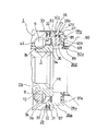
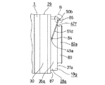
【図1】本発明の実施の形態の第1例を示す断面図。
【図2】カバーのみを取り出して示す斜視図。
【図3】ハーネスの端部及びセンサユニットのみを取り出して示す斜視図。
【図4】図1のA部を、カバーのみを取り出して示す断面図。
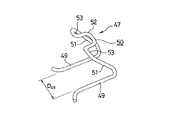
【図5】センサユニットとカバーとを結合する為の結合ばねの斜視図。
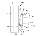
【図6】本発明の実施の形態の第2例を示す、カバーのみを取り出して見た正面図。
【図7】同じく図6の左方から見た図。
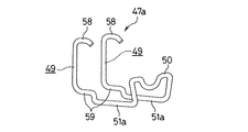
【図8】本発明の実施の形態の第2例に使用する結合ばねの斜視図。
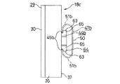
【図9】本発明の実施の形態の第3例を示す、カバーのみを取り出して見た正面図。
【図10】同じく図9の左方から見た図。
【図11】本発明の実施の形態の第3例に使用する結合ばねの斜視図。
【図12】本発明の実施の形態の第4例を示す、図1の右部に相当する部分断面図。
【図13】同第4例に使用するカバーのみを取り出して示す斜視図。
【図14】同じくハーネスの端部及びセンサユニットのみを取り出して示す斜視図。
【図15】同じく1対の結合ばねのうちの一方の結合ばねのみを取り出して示す斜視図。
【図16】同じくカバーとセンサユニットとの結合部のみを示す拡大斜視図。
【図17】本発明の実施の形態の第5例を示す、図1の右部に相当する部分断面図。
【図18】同第5例に使用するカバーのみを取り出して示す部分斜視図。
【図19】同じくハーネスの端部及びセンサユニットのみを取り出して示す斜視図。
【図20】同じく結合ばねのみを取り出して示す斜視図。
【図21】本発明の実施の形態の第6例を示す断面図。
【図22】同じく第6例に使用するカバーのみを取り出して示す斜視図。
【図23】同じくハーネスの端部及びセンサユニットのみを取り出して示す斜視図。
【図24】同じく結合ばねのみを取り出して示す斜視図。
【図25】本発明の実施の形態の第7例を示す、回転速度検出装置付背面組み合わせ型転がり軸受ユニットの内半部の断面図。
【図26】同第7例に使用するカバーのみを取り出して示す斜視図。
【図27】同じくハーネスの端部及びセンサユニットのみを取り出して示す斜視図。
【図28】同じく結合ばねのみを取り出して示す斜視図。
【図29】同じくセンサユニットを未装着のカバーを、搬送する為の状態のまま外輪の端部に装着した状態で示す側面図。
【図30】図29のB部拡大図。
【図31】本発明の実施の形態の第8例に使用するカバーのみを取り出して示す斜視図。
【図32】同じく結合ばねのみを取り出して示す斜視図。
【図33】本発明の実施の形態の第9例を示す、図1の右部に相当する図。
【図34】センサユニットを取り付けたカバーを取り出して示す斜視図。
【図35】結合ばねのみを取り出して示す斜視図。
【図36】結合ばねの摘み部を示す、図35のC矢示図
【図37】カバーに結合ばねを装着する状態を示す部分斜視図。
【図38】カバーに結合ばねを装着した状態を示す部分斜視図。
【図39】結合ばねによりセンサユニットをカバーに抑え付ける作業の途中の状態を示す部分斜視図。
【図40】本発明の実施の形態の第10例を示す、図38のD−D断面に相当する図。
【図41】本発明の実施の形態の第11例を示す、結合ばねの斜視図。
【図42】同例の構造に於いて新たに生じる問題に就いて説明する為、センサユニットを取り付けたカバーを取り出した状態で示す斜視図。
【図43】同じくセンサユニットをカバーに着脱する為、カバーに枢支した結合ばねを揺動させた状態で示す斜視図。
【図44】同じく解決方法の1例を示す、図42と同様の図。
【図45】同じく、図43と同様の図。
【図46】本発明の実施の形態の第12例を示す、センサユニットを取り付けたカバーを取り出した状態で示す斜視図。
【図47】図46の手前側から見た側面図。
【図48】結合ばねのみを取り出して示す斜視図。
【図49】図48のE矢視図。
【図50】同F矢視図。
【図51】本発明の実施の形態の第13例を、結合ばねのみを取り出して示す斜視図。
【図52】図51の下方から見た図。
【図53】図51のG矢視図。
【図54】本発明の実施の形態の第14例を示す、図1の右部に相当する図。
【図55】被覆部材を係止した状態で示す、センサユニットの略断面図
【図56】結合ばねによりセンサユニットをカバーに抑え付け、被覆部材により結合ばねとセンサユニットとの係合部を覆う前の状態で示す部分斜視図。
【図57】同じく被覆部材により結合ばねとセンサユニットとの係合部を覆った後の状態で示す部分斜視図。
【図58】結合ばねのみを取り出して示す斜視図。
【図59】従来構造の1例を示す、図60のH−O−I断面図。
【図60】図59の左方から見た図。
【符号の説明】
1 外輪
2、2a、2b ハブ
3、3a エンコーダ
4 センサ
5a 第一の外輪軌道
5b 第二の外輪軌道
6 ナット
7、7a 内輪
8a 第一の内輪軌道
8b 第二の内輪軌道
9 転動体
10 保持器
11 静止側フランジ
12 回転側フランジ
13 シールリング
15 円筒部
16 円輪部
17 透孔
18、18a、18b、18c、18d、18e、18f、18g、18h、18i、18j、18k カバー
19 嵌合筒部
20 塞ぎ板部
21 膨出部
22 透孔
24 検知部
25 取付フランジ
26 止めねじ
27 スタッド
28、28a、28b 本体
29 嵌合筒
30 嵌合筒部
31 内向鍔部
32 透孔
33 Oリング
34 支持環
35 永久磁石
36、36a 円筒壁部
37、37a、37b 底板部
38、38a、38b 挿入孔
39、39a、39b、39c、39d、39e センサユニット
40、40a、40b、40c 挿入部
41、41a、41b、41c、41d 鍔部
42 Oリング
43 空間
44、44a、44b、44c、44d、44e、44f 係止筒
45、45a、45b 係止凹部
46 ハーネス
47、47a、47b、47c、47d、47e、47f、47g 結合ばね
48、48a、48b 係止溝
49、49a 係止脚部
50、50a、50b 抑え部
51、51a、51b、51c、51d、51e 連結部
52、52a 湾曲部
53、53a 直線部
54、54a 抑え溝
55 湾曲部
56 直線部
57、57a 傾斜面
58 先端側折れ曲がり部
59 基端側折れ曲がり部
60 大径部
61 小径部
62 切り欠き部
63 直線辺部
64 鍔部
65 傾斜辺部
66 第一の係止切り欠き
67 第二の係止切り欠き
68 折れ曲がり係止部
69 段部
70 肩部
71 円筒部
72 枢支片
73 枢支部
74 弾性脚部
75 係止孔
76 係止溝
77 先端側内側面
78 先端側内側面
79 スプライン孔
80 取付フランジ部
81 係止溝
82、82a シールリング
83 平坦部
84、84a 枢支部
85 係止フック
86 傾斜縁
87 段部
88 芯金
89 シールリップ
90 等速ジョイント
91 突出部
92 凹孔
93 枢支孔
94 ストッパプレート
95、95a、95b 結合ばね
96 枢支部
97 抑え部
98 直線部
99 湾曲部
100 摘み部
101、101a、101b、101c 弾性変形部
102 係止突起
103 第一の直線部
104 第二の直線部
105 曲線部
106 摘み部
107 第一の湾曲部
108 第二の湾曲部
109 被覆部材
110 貫通孔
111 突部
112 係止溝
113 第三の直線部
114 庇部
115 段部
[0001]
TECHNICAL FIELD OF THE INVENTION
With rotation speed detecting device according to the present inventionBack combination typeThe rolling bearing unit rotatably supports a wheel of an automobile with respect to a suspension device, and is used for detecting a rotation speed of the wheel.
[0002]
[Prior art]
A rolling bearing unit is used to rotatably support a vehicle wheel with respect to a suspension device. Further, in order to control the antilock brake system (ABS) and the traction control system (TCS), it is necessary to detect the rotation speed of the wheels. Therefore, it is possible to support the wheel rotatably with respect to the suspension device and detect the rotation speed of the wheel by a rolling bearing unit with a rotation speed detection device incorporating the rotation speed detection device in the rolling bearing unit. In recent years, it has been widely practiced.
[0003]
FIGS. 59 to 60 show a rotational speed detecting device used for such a purpose.Rolling bearing unitAn example of the conventional structure described in JP-A-7-31539 is shown. This rolling bearing unit with a rotation speed detecting device rotatably supports a hub 2 which is a rotating wheel which rotates during use, inside an outer ring 1 which is a stationary wheel which does not rotate during use. The rotation speed of the encoder 3 fixed to a part of the hub 2 can be detected by a sensor 4 supported on the outer ring 1. That is, on the inner peripheral surface of the outer ring 1, which is a stationary peripheral surface, a double row ofFirst, secondOuter ring raceway5a, 5bIs provided. The outer peripheral surface of the hub 2, each of which is a rotation-side peripheral surface.The first inner raceway 8a, which is the rotation side raceway,This hub 2Step 115In the state of being fixed to the hub 2 by the nut 6 and being fixed to the outer peripheral surface of the inner ring 7 constituting the rotating wheel together with the hub 2.,alsoIt is the rotation side orbitSecondInner ring track8b, respectivelyProvided. And each of theseFirst, secondInner ring track8a, 8bAnd each of the aboveFirst, secondOuter ring raceway5a, 5bA plurality of rolling elements 9 and 9 are respectively provided between them and are rotatably provided while being held by retainers 10 and 10 respectively. The hub 2 and the inner ring 7 are rotatably provided inside the outer ring 1. I support it.In the case of the example shown in the figure, the outer ring raceways 5a, 5b have smaller inner diameter sides closer to the center, so that a back-to-back type rolling bearing unit is obtained.
[0004]
Also, at the outer end of the hub 2 (the end that is outward in the width direction when assembled to an automobile, and the right end in FIG. 59), a portion protruding outward in the axial direction from the outer end of the outer race 1,For attaching wheelsRotating sideA flange 11 is provided. Further, the inner end of the outer race 1 (the end that is located at the center in the width direction when assembled to an automobile; the left end in FIG. 59) is used to attach the outer race 1 to a suspension device.Stationary flange12 are provided. A gap between the outer end opening of the outer race 1 and the outer peripheral surface of the intermediate portion of the hub 2 is closed by a seal ring 13. In the case of a heavy-duty rolling bearing unit for an automobile, tapered rollers may be used as the plurality of rolling elements 9 instead of balls as shown in the figure.
[0005]
In order to incorporate the rotational speed detecting device into the rolling bearing unit as described above, the inner ring 7 hasSecondInner ring track8bThe encoder 3 is externally fitted and fixed to an outer peripheral surface of a portion deviated from the above. The encoder 3 is formed by subjecting a magnetic metal plate such as a mild steel plate to plastic working so as to have an L-shaped cross section as a whole, and is provided with a cylindrical portion 15 and a circular ring portion 16. The portion 15 is fixed to the inner end of the inner ring 7 by fitting the outer end to the inner end of the inner ring 7 with an interference fit. The annular portion 16 is formed by forming a large number of slit-shaped through holes 17, 17, which are long in the diameter direction of the annular portion 16, radially at equal intervals in the circumferential direction. The magnetic properties of the circular ring portion 16 are changed alternately at regular intervals in the circumferential direction.
[0006]
Further, a cover 18 is fitted and fixed to the inner end opening of the outer ring 1 in a state of facing the inner side surface of the circular ring portion 16 of the encoder 3. The cover 18, which is formed by plastically processing a metal plate, has a fitting cylindrical portion 19 that can be fitted and fixed in the inner end opening of the outer race 1, and a closing plate portion 20 that closes the inner end opening. At the center of the closing plate portion 20, a bottomed cylindrical bulging portion 21 is formed to prevent interference between the closing plate portion 20 and the nut 6. Further, a through hole 22 is formed in a portion of the closing plate portion 20 closer to the outer periphery in a diameter direction outside of the bulging portion 21, and the detecting portion 24 of the sensor 4 is connected to the cover 18 through the through hole 22. Inserted inside. A mounting flange 25 is fixed to the outer peripheral surface of the intermediate portion of the sensor 4. The mounting flange 25 is fixed to the closing plate portion 20 of the cover 18 with set screws 26, 26, whereby the sensor 4 is mounted. 4 is fixedly connected to the cover 18 in a predetermined positional relationship. In a state where the sensor 4 is fixedly connected to the cover 18 in this manner, the distal end surface of the detection unit 24 faces the inner side surface of the ring portion 16 of the encoder 3 via a small gap.
[0007]
With rotation speed detector as described aboveBack combination typeWhen the rolling bearing unit is used, it is fixed to the outer peripheral surface of the outer ring 1.Stationary flange12 is fixed to the suspension by a bolt (not shown) and fixed to the outer peripheral surface of the hub 2.Rotating sideWheels on flange 11Rotating sideBy fixing with the stud 27 provided on the flange 11, the wheel is rotatably supported with respect to the suspension device. When the wheel rotates in this state, the vicinity of the end face of the detection portion 24 of the sensor 4 is moved between the through holes 17 formed in the annular portion 16 and the through holes 17 adjacent in the circumferential direction. The existing pillars pass alternately. As a result, the density of the magnetic flux flowing in the sensor 4 changes, and the output of the sensor 4 changes. The frequency at which the output of the sensor 4 changes in this way is proportional to the rotation speed of the wheel. Therefore, if the output of the sensor 4 is sent to a controller (not shown), the ABS and TCS can be appropriately controlled.
[0008]
[Problems to be solved by the invention]
The present inventionIs equipped with such a rotational speed detectorBack combination typeRolling bearing unitAbout improvement.
[0009]
[Means for Solving the Problems]
With rotation speed detection device of the present inventionBack combination typeRolling bearing unitIn each case,
A stationary flange for attaching to a suspension device is provided on the outer peripheral surface, and first and second outer rings are provided on the inner peripheral surface.Orbit,RespectivelyHas no rotation when usedOutsideWith a circle
A rotating flange for attaching a wheel to the outer peripheral surface of one end, a first inner raceway facing the first outer raceway on the outer peripheral surface of the intermediate portion, and a step portion on the outer peripheral surface of the other end, respectively.Has and rotates when usedHubWhen,
The outer peripheral surface has a second inner raceway facing the second outer raceway, and a portion protruding from the end surface at the other end of the hub in a state of being externally fitted to the step portion is diametrically outward. By crimping and spreading, the inner ring connected and fixed to this hub,
the aboveFirst, secondOuter ring raceway and aboveFirst and second inner ringsA plurality of rolling elements provided rotatably between the track and
the aboveInsideThis part of the ringInsideCircumferentially fixed, concentric with the ringMagneticAn encoder whose characteristics are changed alternately and at equal intervals; and
the aboveOutsideWheeledgeA cover fixed to the
thiscoverToSupportedIn the stateOf the above encoderFaced to the surface to be detectedWith sensor,
The support ring has a cylindrical portion and a ring portion formed by bending a magnetic metal plate, and is entirely formed in an annular shape. The above-mentioned permanent magnet is attached to the loop part.
[0010]
In particular, with the rotation speed detection device of the present inventionBack combination typeRolling bearing unit2. The back-to-back combination type rolling bearing unit with the rotation speed detecting device according to claim 1.InThe detected surface of the encoder has a pitch circle of a plurality of rolling elements rolling on the second inner raceway. It has a portion smaller in diameter than the diameter and a portion larger in diameter.
[0011]
orWith the rotation speed detecting device according to claim 2.Back combination typeIn a rolling bearing unit,The detected surface of the encoder has a portion having a diameter smaller than a diameter of a maximum diameter portion of the second inner raceway and a portion having a larger diameter..
[0012]
[0013]
[0014]
[Action]
The rolling bearing unit with the rotation speed detection device of the present invention configured as described above rotatably supports the wheel with respect to the suspension system of the automobile, and the operation itself when detecting the rotation speed of the wheel is as described above. Same as the conventional structureIt is.
[0015]
[0016]
[0017]
[0018]
BEST MODE FOR CARRYING OUT THE INVENTION
1 to 5 show a first example of an embodiment of the present invention. BookAn exampleIs characterized by the structure of the part where the sensor is mounted on the cover fixed to the end of the stationary wheel constituting the rolling bearing unit. The structure and operation of the rolling bearing unit, which rotatably supports the rotating wheel with respect to the stationary wheel, are basically the same as the conventional structure shown in FIGS. The same reference numerals are given and duplicate explanations are omitted or simplified.An exampleThe following description focuses on the characteristic portions of FIG. BookAn exampleIn FIG. 59, the inside and outside directions in the width direction of the vehicle are left and right reversed from FIG. 59 showing the above-described conventional structure.
[0019]
An opening at the inner end (right end in FIG. 1) of the outer ring 1 which is a stationary wheel is closed by a cover 18a. The cover 18a includes a bottomed cylindrical main body 28 formed by injection molding of a synthetic resin, and a fitting cylinder 29 coupled to an opening of the main body 28. The fitting tube 29 is formed by plastically deforming a corrosion-resistant metal plate such as a stainless steel plate. The fitting tube 29 has an L-shaped cross section and is entirely annular. An inward flange portion 31 is bent inward in the diametric direction from the edge (the right edge in FIG. 1). Such a fitting cylinder 29 is connected to the opening of the main body 28 by molding the inward flange portion 31 during the injection molding of the main body 28. The inward flange portion 31 has a large number of through holes 32, 32 formed intermittently in the circumferential direction. The synthetic resin constituting the main body 28 flows into the inside of each of the through holes 32 at the time of injection molding of the main body 28, and increases the bonding strength between the main body 28 and the fitting cylinder 29.
[0020]
The cover 18a configured as described above secures the fitting cylinder portion 30 of the fitting cylinder 29 to the inner end of the outer ring 1 by external fitting with an interference fit, thereby opening the inner end opening of the outer ring 1. I'm blocking. In this state, the end face of the opening of the main body 28, that is, the front end face of the cylindrical wall portion 36 formed on the outer peripheral edge of the main body 28 is brought into contact with the inner end face of the outer ring 1. A locking groove is formed all around the distal end surface of the cylindrical wall portion 36, and the O-ring 33 is locked in the locking groove. When the distal end surface of the cylindrical wall portion 36 and the inner end surface of the outer ring 1 are in contact with each other, the O-ring 33 is elastically compressed between the inner end surface and the bottom surface of the locking groove, The joint between the cover 18a and the outer ring 1 is sealed to prevent foreign matter such as muddy water from entering the cover 18a.
[0021]
On the other hand, an encoder 3a is externally fitted and fixed to the inner end (the right end in FIG. 1) of the inner ring 7 that forms a rotating wheel together with the hub 2. The encoder 3a includes a support ring 34 and a permanent magnet 35. The support ring 34 is formed by bending a magnetic metal plate such as SPCC or the like to have an L-shaped cross section as a whole, and is externally fixed to the inner end of the inner ring 7 by interference fitting. In addition, the permanent magnet 35 is formed by, for example, attaching rubber mixed with ferrite powder to the inner surface of the annular portion forming the support ring 34 by baking or the like. The permanent magnets 35 are magnetized, for example, in the axial direction (left-right direction in FIG. 1), and the magnetization directions are alternately changed at equal intervals in the circumferential direction. Therefore, on the inner surface of the encoder 3a, S poles and N poles are arranged alternately and at equal intervals in the circumferential direction.
[0022]
An insertion hole 38 is formed in a part of the bottom plate 37 of the main body 28 forming the cover 18a and facing the inner surface of the permanent magnet 35 forming the encoder 3a. Thus, the outer ring 1 is formed in the axial direction. In the insertion hole 38, a portion near the tip of the sensor unit 39 corresponding to the sensor or the holder holding the sensor is inserted. This sensor unit 39 incorporates a magnetic detecting element such as a Hall element and a magnetoresistive element (MR element) that changes its characteristics in accordance with the flow direction of magnetic flux, and a waveform shaping circuit for adjusting the output waveform of this magnetic detecting element. An IC and a pole piece or the like made of a magnetic material for guiding a magnetic flux from the permanent magnet 35 (or flowing into the permanent magnet 35) to the magnetic detection element are embedded in a synthetic resin. Further, an end of a harness 46 for sending an output signal output as a shaped waveform from the IC to a controller (not shown) is directly connected to the sensor unit 39 (without a connector or the like). Therefore, the connector is omitted and the rotation speed detector isBack combination typeThe cost of the rolling bearing unit can be reduced.
[0023]
Such a sensor unit 39 is provided near the tip (left end in FIG. 1), and has a columnar insertion portion 40 through which the insertion hole 38 can be inserted without looseness, and a base end portion of the insertion portion 40 ( An outward flange-shaped flange portion 41, which is a positioning portion, is formed at the right end of FIG. 1). A locking groove is formed in the outer peripheral surface of the intermediate portion of the insertion portion 40, and the O-ring 42 is locked in the locking groove. When the insertion portion 40 is inserted through the insertion hole 38, the O-ring 42 is elastically compressed between the inner peripheral surface of the insertion hole 38 and the bottom surface of the locking groove, and Is sealed between the outer peripheral surface and the inner peripheral surface of the insertion hole 38. That is, the O-ring 42 prevents foreign matter such as muddy water from entering the inside of the cover 18 a and the outer ring 1 through the insertion hole 38. In this manner, the O-ring 33 seals the connecting portion between the outer ring 1 as a stationary wheel and the cover 18a, and the O-ring 42 seals the insertion portion of the sensor unit 39 into the cover 18a, thereby rolling. By preventing foreign matter from entering the bearing unit, the durability of the rolling bearing unit is ensured, and foreign matter such as magnetic powder is prevented from adhering to the side surface of the permanent magnet 35 constituting the encoder 3a. This prevents the accuracy of the device from deteriorating. As a seal ring for sealing the insertion portion of the sensor unit 39 with respect to the cover 18a, another seal ring such as an X ring having an X-shaped cross section is used instead of the O ring 42 as described above. Then, the force required to insert the insertion portion 40 of the sensor unit 39 into the insertion hole 38 can be reduced, and the mounting work of the sensor unit 39 can be facilitated.
[0024]
On the other hand, a part of the outer surface of the bottom plate portion 37 constituting the cover 18a (a side surface opposite to the space 43 in which the rolling elements 9, 9 to be closed by the cover 18a is installed, and a right side surface in FIG. 1) A locking cylinder 44 is provided around the opening of the insertion hole 38. The inner peripheral surface of the locking cylinder 44 and the inner peripheral surface of the insertion hole 38 constitute a single cylindrical surface. Therefore, in the case of this example, the opening end face of the locking cylinder 44 corresponds to the opening peripheral portion of the insertion hole 38. Further, locking concave portions 45 are provided at two positions on the outer peripheral surface of the locking cylinder 44 on the opposite side in the diameter direction, respectively. Each of the locking recesses 45 has a width sufficiently larger than the outer diameter of a wire constituting the coupling spring 47 described below. Then, on one inner side surface, on the inner side surface at the distal end side (the right side in FIGS. 1 and 4) of the locking cylinder 44, locking grooves 48, 48 having an arc-shaped cross section are formed over the entire width of the locking recesses 45, 45. It is formed over. The radius of curvature of the cross section of each of the locking grooves 48 is the same as or slightly larger than the radius of curvature of the outer peripheral surface of the wire constituting the coupling spring 47.
[0025]
The flange portion 41 provided at the base end of the sensor unit 39 and functioning as a positioning portion is brought into contact with the distal end surface (the right end surface in FIGS. 1 and 4) of the locking cylinder 44 formed as described above, The coupling cylinder 47 is coupled and fixed to the locking cylinder 44 by a coupling spring 47 described below. The coupling spring 47, which is an elastic member, is formed by bending a wire having elasticity and corrosion resistance, such as stainless steel, chrome-plated or zinc-plated spring steel. When a plated wire is used, dehydrogenation is performed to prevent delayed destruction. The coupling spring 47 presses the pair of locking legs 49, 49, which are parallel to each other at least in the assembled state to the locking cylinder 44, and the flange 41 toward the distal end surface of the locking cylinder 44. And a pair of connecting portions 51 for connecting both ends of the pressing portion 50 and the base ends (upper right ends in FIG. 5) of the locking legs 49, 49. 51. The restraining portion 50 has a U-shaped curved portion 52 at an intermediate portion, and linear portions 53, 53 bent at opposite ends from opposite ends of the curved portion, respectively. One end of each of the connecting portions 51, 51 is bent in the same direction from the end of each of the linear portions 53, 53.
[0026]
In such a coupling spring 47, at least in a use state, a plane including the pair of locking legs 49, 49 and a plane including the pressing portion 50 are parallel to each other. However, in the free state of the coupling spring 47, the angle of the continuous portion between one end of each of the connecting portions 51, 51 and the base end of each of the locking legs 49, 49 is reduced so that the distance between these planes is reduced. The elasticity in the direction of reducing The distance D between the main body portions of the pair of locking legs 49, 49 in a free state.49(FIG. 5) shows the distance D between the locking recesses 45.45(FIG. 4)49<D45)are doing. Further, the tips of the pair of locking legs 49, 49 are bent in opposite directions, and the distance between the tips of the locking legs 49, 49 increases toward the ends. I am doing it.
[0027]
On the other hand, on the base end surface of the flange portion 41 provided on the sensor unit 39 (the surface opposite to the insertion portion 40, the right end surface in FIG. 1 and the front surface in FIG. 3), the holding portion 50 of the coupling spring 47 is provided. A retaining groove 54 is formed for engaging without rattling. The holding groove 54 includes a curved portion 55 provided so as to surround the base end of the harness 46, and a straight portion 56 that is bent in opposite directions from both ends of the curved portion 55 and opens at the outer peripheral edge of the flange 41. , 56. An inclined surface 57 is formed in a portion of the base end surface of the flange portion 41 that faces the convex side of the curved portion 55. The inclined surface 57 is inclined in such a direction that the thickness of the flange 41 becomes smaller toward the edge of the flange 41.
[0028]
Combine each member configured as described above,An exampleWith rotation speed detectorBack combination typeThe operation of mounting the sensor unit 39 on the cover 18a so as to constitute a rolling bearing unit is performed as follows. First, the insertion portion 40, which is a portion near the front end of the sensor unit 39, is inserted into the locking tube 44 and the insertion hole 38, and the flange portion 41 is brought into contact with the front end surface of the locking tube 44. In this state, a desired thickness dimension (for example, 0.5 mm) is provided between the detecting portion provided on the distal end surface of the insertion portion 40 constituting the sensor unit 39 and the inner surface of the permanent magnet 35 constituting the encoder 3a. The size of each part is regulated so that a minute gap (about) exists. Next, a coupling spring 47 is mounted between the locking cylinder 44 provided on the cover 18a and the sensor unit 39, and the flange 41 is pressed against the distal end surface of the locking cylinder 44.
[0029]
As described above, the work of mounting the coupling spring 47 between the locking cylinder 44 provided on the cover 18a and the sensor unit 39 is performed by a pair of locking legs 49 constituting the coupling spring 47, This is achieved by inserting the locking 49 into the locking recesses 45 of the locking cylinder 44 from the distal ends of the locking legs 49. Since the distance between the distal ends of the locking legs 49, 49 becomes larger toward the ends, this insertion operation can be easily performed. As the insertion operation progresses, the linear portions 53 of the holding portion 50 ride on the inclined surface 57 formed on the flange portion 41. If the insertion operation is further continued from this state, the holding portion 50 engages with the holding groove 54 formed on the base end surface of the flange portion 41. During the insertion operation, a part of the pair of connecting portions 51, 51 facing the outer peripheral edge of the flange 41 does not interfere with the outer peripheral edge of the flange 41 so that the pair of connecting portions 51, 51 does not interfere with the outer peripheral edge of the flange 41. The interval between portions of the connecting portions 51, 51 close to the suppressing portion 50 is slightly larger than the outer diameter of the flange portion 41.
[0030]
As described above, when the holding portion 50 is engaged with the holding groove 54, the coupling spring 47 directs the flange 41 toward the end face of the locking cylinder 44 with a sufficiently large force (for example, about 10 kgf). By pressing, the sensor unit 39 is connected to the cover 18a. In this state, the coupling spring 47 is engaged based on the engagement between the locking legs 49, 49 and the locking grooves 48, 48 and the engagement between the holding portion 50 and the holding groove 54. Does not accidentally come off from the sensor unit 39 and the locking cylinder 44. As a result, the sensor unit 39 does not accidentally come off the cover 18a.
[0031]
When removing the sensor unit 39 from the cover 18a, the coupling spring 47 is first removed from between the cover 18a and the sensor unit 39, contrary to the mounting operation described above. The detaching operation is performed by first lifting the holding portion 50 from the base end surface of the flange portion 41 and then removing the pair of locking legs 49, 49 from the locking concave portions 45, 45. After removing the coupling spring 47 in this manner, the insertion portion 40 of the sensor unit 39 is pulled out from the inside of the insertion hole 38 and the locking cylinder 44.
[0032]
The operation of attaching and detaching the coupling spring 47 between the locking cylinder 44 provided on the cover 18a and the sensor unit 39 can be performed easily and quickly as compared with the operation of tightening or loosening the set screw. . Therefore, including this exampleConfiguration of each exampleAccording to the present invention, the time required for the operation of attaching and detaching the sensor unit 39 to and from the cover 18a is reduced, and the rotation speed detecting device is provided.Back combination typeThe cost of the rolling bearing unit itself and the cost required for repair can be reduced.
[0033]
In the above description, the distance D in the free state between the pair of locking legs 49 constituting the coupling spring 47 is described.49Is provided on the outer peripheral surface of the locking cylinder 44 by a distance D between a pair of locking recesses 45,45And locking grooves 48, 48 are formed in these locking recesses 45, 45, respectively. However, the above interval D49To the above interval D45If it is smaller, the locking grooves 48 need not necessarily be provided. For example, as shown in FIG. 1, even if each of the locking recesses 45 is formed in a groove shape that allows the locking legs 49 to be fitted without looseness, these locking legs The portions 49, 49 can be prevented from being accidentally detached from the locking recesses 45, 45. Conversely, if the locking grooves 48 are provided, the distance D is not necessarily required.49To the above interval D45Even if not made smaller, it is possible to prevent the locking legs 49, 49 from accidentally coming off the locking recesses 45, 45. However, in order to secure a sufficient coupling strength between the cover 18a and the sensor unit 39 by the coupling spring 47, and to make the attaching and detaching operation of the coupling spring 47 easier, the shape shown in FIGS. And a combination of dimensions.
[0034]
Next, FIGS. 6 to 8 show a second example of the embodiment of the present invention. In the case of this example, the locking cylinder 44a formed on the outer surface of the cover 18b is formed by a large-diameter portion 60 closer to the base end (leftward in FIG. 7) and a small-diameter portion 61 closer to the front end (rightward in FIG. 7). Make up. Of these, locking recesses 45a, 45a are formed at two positions on the opposite side in the diameter direction of the outer peripheral surface of the base end half of the large diameter portion 60, respectively. The width (the left-right dimension in FIG. 7) of each of the locking recesses 45a, 45a is sufficiently larger than the outer diameter of a wire constituting the coupling spring 47a. On the other hand, distal ends and proximal ends of a pair of locking legs 49, 49 constituting the coupling spring 47a are bent toward the distal end of the locking cylinder 44a, respectively, and are bent toward the distal end 58, 58. And bent portions 59, 59 on the proximal end side. Further, one ends of the connecting portions 51a, 51a are connected to the base ends of the locking legs 49, 49, respectively, and the holding portion 50 is connected to the other end of each of the connecting portions 51a, 51a. It is provided in a state of being bent in the same direction as the locking legs 49, 49.
[0035]
The coupling spring 47a as described above loosely engages the locking legs 49, 49 inside the locking recesses 45a, 45a, and connects the distal bent portions 58, 58 to the large diameter. A part of the outer peripheral surface of the front end half portion of the portion 60 is engaged with the notch portions 62, 62 formed at positions matching with one end portions (upper end portions in FIGS. 6 and 7) of the locking recesses 45a, 45a. ing. The distal ends of the bent portions 58, 58 are slightly bent toward the locking legs 49, 49, and the bent portions are locked to the distal end surface of the large diameter portion 60. In this state, the coupling spring 47a is swingably supported by the side of the locking cylinder 44a. In addition, the holding portion 50 can move forward and backward toward the opening of the locking cylinder 44a, which also serves as the opening of the insertion hole 38, with this swing. In a state where the sensor unit 39 (see FIGS. 1 and 3) is not actually mounted on the automobile, the coupling spring 47a swings by its own weight to a state shown by a chain line in FIGS. The part 50 retreats from the opening of the locking cylinder 44a.
[0036]
The sensor unit 39 that is coupled to the locking cylinder 44a configured as described above using the coupling spring 47a configured as described above has a configuration similar to that of the first example illustrated in FIGS. are doing. In order to hold and fix such a sensor unit 39 inside the locking tube 44a, as shown by a chain line in FIGS. 6 and 7, the holding unit 50 is retracted from the opening of the locking tube 44a. Then, the insertion portion 40 of the sensor unit 39 is inserted into the inside of the locking cylinder 44a and into the insertion hole 38, and the flange 41 is brought into contact with the distal end surface of the locking cylinder 44a. Next, the pressing portion 50 is pressed upward as indicated by an arrow α in FIGS. 6 and 7, and the pressing portion 50 is engaged with the pressing groove 54 formed on the base end surface of the flange portion 41 (sensor). (See FIGS. 1 and 3 for the components of the unit 39.) Conversely, when removing the sensor unit 39 from the cover 18b, the restraining portion 50 is displaced in the direction opposite to the arrow α, and the restraining portion 50 is retracted from the opening of the locking cylinder 44a. Then, the insertion portion 40 of the sensor unit 39 is pulled out from the inside of the locking cylinder 44a and the inside of the insertion hole 38. Also in the case of the present embodiment configured and operated as described above, the time required for the operation of attaching and detaching the sensor unit 39 to and from the cover 18a is reduced, and the rotation speed detecting device is provided.Back combination typeThe cost of the rolling bearing unit itself and the cost required for repair can be reduced.
[0037]
Next, FIGS. 9 to 11 show a third example of the embodiment of the present invention. In the case of this example, a flange 64 having a pair of straight sides 63, 63 parallel to each other is formed on the outer peripheral edge of the distal end of the locking cylinder 44b provided on the outer surface of the cover 18c. In the case of this example, a portion between the outer surface of the cover 18c and one surface of the flange portion 64 serves as locking concave portions 45b for engaging the locking legs 49 of the coupling spring 47b, which will be described later. . Further, a pair of inclined sides 65, 65 are formed at one end (the left end in FIG. 9) of the flange 64 so that the width of the flange 64 decreases toward the one end. . Further, first locking notches 66, 66 and second locking notches 67, 67 are formed at two positions on the straight side portions 63, 63, respectively, so as to be aligned with each other. . Among these, one side edge of the first locking notch 66, 66 provided on the inclined side portion 65, 65 side on the side of the second locking notch 67, 67 is formed at the edge of the flange portion 64. As they move, they are inclined in the direction toward the second locking notches 67, 67. The width of the other end (the right end in FIG. 9) of the flange portion 64 that partitions one side surface (the right side surface in FIG. 9) of the second locking notches 67, 67 is equal to the width of the adjacent first notch. , The second locking notches 66, 67 are larger than the width of the portion between them.
[0038]
On the other hand, the coupling spring 47b for coupling and fixing the sensor unit 39 (see FIGS. 1 and 3) to the cover 18b as described above includes a pair of locking legs 49, 49 and a pair of locking legs. A holding portion 50 is provided so as to bridge between 49 and 49. Both ends of the holding portion 50 and the tips of the pair of locking legs 49, 49 (the left end in FIG. 9 and the lower left end in FIG. 11) are connected by curved connecting portions 51b, 51b. I have. Each of the connecting portions 51b, 51b has elasticity in a direction in which both ends of the holding portion 50 and the pair of locking legs 49, 49 approach each other in a free state.
[0039]
Further, at the base ends (right end in FIG. 9 and upper right end in FIG. 11) of the locking legs 49, 49, bent locking portions 68, 68 bent toward the flange 64 are provided. Has formed. In the illustrated example, the distance between the pair of bent locking portions 68 is greater than the distance between the pair of locking legs 49. The reason for this is that the engagement depth between each of the engagement leg portions 49, 49 and the engagement recesses 45b, 45b is ensured, and the coupling strength of the sensor unit 39 by the coupling spring 47b is secured. This is to prevent the locking force between each of the bending locking portions 68, 68 and the first and second locking notches 66, 67 from becoming excessively large.
[0040]
The coupling spring 47b having the above-described shape is supported by the locking cylinder 44b so as to be movable in parallel along the straight sides 63, 63. In this state, the holding portion 50 can move forward and backward toward the opening of the locking cylinder 44b, which also serves as the opening of the insertion hole 38, in accordance with the parallel movement. In a state where the sensor unit 39 is not mounted on the vehicle, the coupling spring 47b is connected to each of the bent locking portions 68, 68 and the first locking cutoff as shown by a chain line in FIG. With the notches 66 and 66 engaged, the holding portion 50 is retracted from the opening of the locking cylinder 44b. With rotation speed detectorBack combination typeIn this way, the rolling bearing unit is supplied from the maker that manufactures the rolling bearing unit to the automobile assembling factory in a state where the bending locking portions 68, 68 and the first locking notches 66, 66 are engaged. . In such a state, the coupling spring 47b does not protrude radially outward from the outer peripheral surface of the cover 18c. Therefore, the coupling spring 47b inserts the cover 18c into a support hole of a knuckle (not shown) andBack combination typeIt does not hinder the operation of supporting the rolling bearing unit on the suspension of the vehicle.
[0041]
The sensor unit 39 which is coupled to the locking cylinder 44b configured as described above using the coupling spring 47b also configured as described above is similar to the case of the first example illustrated in FIGS. Make up. In order to hold and fix such a sensor unit 39 inside the locking cylinder 44b, the holding unit 50 is retracted from the opening of the locking cylinder 44b as shown by a chain line in FIG. The insertion portion 40 of the sensor unit 39 is inserted into the inside of the locking cylinder 44b and into the insertion hole 38, and the flange 41 of the sensor unit 39 is brought into contact with the distal end surface of the locking cylinder 44b. Next, the pressing portion 50 is pressed rightward (outward in the diametric direction) in FIG. 9, and the pressing portion 50 is engaged with the pressing groove 54 formed on the base end surface of the flange portion 41 (sensor unit). 39, refer to FIGS. 1 and 3). In the state in which the holding portion 50 and the holding groove 54 are engaged in this manner, the bending engagement portions 68, 68 and the second engagement notches 67, 67 are engaged.
[0042]
When the sensor unit 39 is fixedly coupled to the cover 18c by the coupling spring 47b in this manner, the bent engagement portions 68, 68 are moved from the first engagement notches 66, 66 to the respective It moves to the second locking notches 67, 67. In the case of the structure of this example, this movement can be easily performed because one side edge of each of the first locking notches 66, 66 is inclined. Further, since the width of the other end of the flange portion 64 is larger than the width of the portion between the adjacent first and second locking notches 66 and 67, each of the bending locking portions 68 , 68 do not overshoot the second locking notches 67, 67.
[0043]
When the sensor unit 39 is detached from the cover 18c, the coupling spring 47b is displaced to the left in FIG. 9 until the state shown by the chain line in FIG. The operation of displacing the coupling spring 47 in this manner is performed while floating the holding portion 50 from the base end surface of the flange portion 41 and widening the interval between the bent locking portions 68. After the holding portion 50 is retracted from the opening of the locking cylinder 44b in this manner, the insertion portion 40 of the sensor unit 39 is removed from the inside of the locking cylinder 44b and from the inside of the insertion hole 38. Also in the case of the present embodiment configured and operated as described above, the time required for the operation of attaching and detaching the sensor unit 39 to and from the cover 18c is reduced, and the rotation speed detecting device is provided.Back combination typeThe cost of the rolling bearing unit itself and the cost required for repair can be reduced.
[0044]
Next, FIGS. 12 to 16 show a fourth example of the embodiment of the present invention. In the case of this example, the sensor unit 39a is fixedly connected to the locking cylinder 44c formed on the cover 18d by a pair of connecting springs 47c. For this purpose, a pair of pivotal support pieces 72, 72 are formed at two positions on the diametrically opposite side of a part of the outer peripheral surface of the locking cylinder 44c with a space between each pair. ing. These pivoting pieces 72, 72 are formed in an arch shape, and pivotally supporting portions 73, 73 formed at both ends of each of the coupling springs 47c, which will be described below, are pivotally supported on the inside thereof. And In the above set of the pivot pieces 72, 72, the pair of coupling springs 47c, 47c pivotally supported by the set of the pivot pieces 72, 72 interfere with other components as the rocking motions. In order to prevent this from happening, the locking cylinder 44c is provided on the outer circumferential surface of the locking cylinder 44c on the circumferentially opposite side.
[0045]
As shown in FIG. 15, each of the pair of coupling springs 47c, 47c has a linear holding portion 50a and a pair of pivoting portions 73, 73, each of which has an elastic leg portion bent in a "U" shape. 74, 74 are connected. These elastic legs 74, 74 are elastically deformed in the elongating direction when a force in the pulling direction is applied, and allow the restraining portion 50a and the pivots 73, 73 to separate from each other. The direction of the pair of pivots 73, 73 provided at both ends of the coupling springs 47c, 47c is set in the direction of the pivot pieces 72, 72 at which the pivots 73, 73 are to be pivoted. Together, they are inclined to each other. The distance D between the distal ends of the pair of pivots 73, 73 in the free state.73Is a distance D between the pair of pivot pieces 72, 72 that constitute a set.72Much larger than (D73> D72)are doing.
[0046]
On the other hand, on the base end surface of the flange portion 41a constituting the sensor unit 39a, parallel restraining grooves 54a, 54a are formed so as to sandwich the harness 46. The holding portions 50a, 50a of the coupling springs 47c, 47c can be freely engaged with these both holding grooves 54a, 54a without rattling. In addition, inclined surfaces 57a, 57a are formed in the positions closer to the outer peripheral edge than the holding grooves 54a, 54a at positions opposite to the diameter direction of the base end surface of the flange 41a, and the thickness of the flange 41a is reduced. The width of each of the holding grooves 54a, 54a is reduced toward the edge of the flange 41a.
[0047]
In order to hold and fix the sensor unit 39a as described above inside the locking cylinder 44c, the pivot portions 73, 73 of the pair of coupling springs 47c, 47c are previously set to the pair of pivot pieces 72, respectively. , 72. This engagement operation can be easily performed in a large space. Then, the pair of coupling springs 47c, 47c are pivotally displaced to the side of the locking cylinder 44c, and the holding portions 50a, 50a of the coupling springs 47c, 47c are retracted from the opening of the locking cylinder 44c. In this state, the insertion section 40 of the sensor unit 39a is inserted into the inside of the locking cylinder 44c and into the insertion hole 38, and the flange 41a is brought into contact with the distal end surface of the locking cylinder 44c. In this state, a small gap having a desired size exists between the detecting portion provided on the distal end surface of the insertion portion 40 constituting the sensor unit 39a and the inner side surface of the annular portion 16 constituting the encoder 3. In addition, the size of each part is regulated. Next, the pair of coupling springs 47c, 47c is rocked and displaced in a direction in which the respective holding portions 50a, 50a approach the flange portion 41a, and the respective holding portions 50a, 50a and the flange portion 41a are displaced. A pair of holding grooves 54a, 54a formed on the base end face are engaged. At this time, the respective elastic legs 74, 74 are elastically extended based on the engagement between the respective holding portions 50a, 50a and the respective inclined surfaces 57a, 57a. In a state where the holding portions 50a, 50a are aligned with the holding grooves 54a, 54a, the entire lengths of the elastic legs 74, 74 are elastically reduced, and the holding portions 50a, 50a and the holding grooves 54a , 54a remain engaged.
[0048]
When the sensor unit 39a is detached from the cover 18d, the coupling springs 47c, 47c are displaced to the side of the locking cylinder 44c in the opposite direction to the time of the mounting operation. The retaining portions 50a, 50a of the coupling springs 47c, 47c are removed from the retaining grooves 54a, 54a. In this manner, the holding portions 50a, 50a are removed from the holding grooves 54a, 54a, and the holding portions 50a, 50a are retracted from the opening of the locking cylinder 44c. The insertion portion 40 is removed from the inside of the locking cylinder 44c and the inside of the insertion hole 38. Also in the case of the present embodiment configured and operated as described above, the labor required for attaching and detaching the sensor unit 39b to and from the cover 18d can be reduced, and a rotation speed detecting device can be provided.Back combination typeThe cost of the rolling bearing unit itself and the cost required for repair can be reduced.
[0049]
In this case, in the case of the present example, the above-described drawing59An encoder 3 similar to the encoder incorporated in the conventional structure shown in FIG. In particular, in the case of the structure of this example, the inner end of the inner ring 7aSecondInner ring track8bA small-diameter stepped portion 69 is formed concentrically with the inner ring 7a over the entire circumference at a portion deviated in the axial direction from the inner ring 7a. The cylindrical portion 15 constituting the encoder 3 is externally fitted and fixed to the step portion 69.The detected surface of the encoder 3 has a diameter d of a pitch circle of a plurality of rolling elements 9 and 9 rolling on the second inner raceway 8b. 9 It has a smaller diameter portion and a larger diameter portion. The detected surface of the encoder 3 has a diameter d of the largest diameter portion of the second inner raceway 8b. 8b It has a smaller diameter portion and a larger diameter portion. the aboveThe reason for forming the step portion 69 is to make the encoder 3 face the distal end surface of the insertion portion 40 constituting the sensor unit 39a without increasing the diameter of the cover 18d.
[0050]
That is, even when a large thrust load or moment load is applied to the rolling bearing unit, the rolling elements 9, 9 are prevented from coming off the inner raceway 8 provided on the outer peripheral surface of the inner race 7a. At the inner endSecondInner ring track8bIt is necessary to form a shoulder portion 70 having a sufficiently large outer diameter at a portion deviated in the axial direction from the outer periphery. On the other hand, in order to detect the rotation speed of the rotating wheel including the inner ring 7a, it is necessary that the circular ring portion 16 constituting the encoder 3 and the distal end face of the insertion portion 40 face each other. When the cylindrical portion 15 constituting the encoder is fitted on the shoulder portion 70 itself, the diameter of the annular portion 16 becomes larger than necessary, and a cover 18d for supporting and fixing the sensor unit 39a facing the annular portion 16 is provided. May also be larger than necessary. On the other hand, if the above-described step portion 69 is provided, and the encoder 3 is externally fitted and fixed to the step portion 69, it is possible to prevent the diameter of the encoder 3 and the cover 18d from becoming unnecessarily large. With small rotation speed detectorBack combination typeThis can contribute to the realization of a rolling bearing unit. Such a structure is, of course, not limited to this example, and can be applied to other embodiments.
[0051]
Further, in the case of the illustrated example, a cylindrical portion 71 is formed at the inner end of the hub 2a, and a portion protruding from the inner end surface of the inner ring 7a at the distal end of the cylindrical portion 71 is caulked radially outward. By expanding, the inner ring 7a is fixedly connected to the hub 2a. If such a structure is adopted, it is compared with the conventional structure shown in FIG. 59 described above or the structure in which the inner ring and the hub are connected and fixed by a nut as in the first example of the embodiment shown in FIG. Thus, cost can be reduced by reducing the number of parts and the labor for assembling. When the tip of the cylindrical portion 71 is crimped outward in the diametric direction, a force directed diametrically outward is applied to a part of the inner ring 7a. If this load is large,SecondInner ring track8bMay change, and the preload applied to the rolling elements 9 may change. However, in the case of this example, the stepped portion 69 receives the force accompanying the swaging andSecondInner ring track8bThis force is hardly applied to the part. Therefore, the preload hardly changes. Such a structure can also be applied to other embodiments.
[0052]
In the case of the present embodiment, an example in which the encoder 3 is made of a magnetic material and has a plurality of slit-shaped through holes 17 formed in the circular ring portion 16 has been described. Therefore, the structure of the sensor incorporated in the sensor unit 39a is also different from that using a permanent magnet as an encoder.I have.When an MR element is used for the sensor, it is necessary to regulate the arrangement direction of the MR elements in relation to the longitudinal direction of the through hole 17 (diameter direction of the annular portion 16). In the case of this example, the direction of the sensor unit 39a with respect to the cover 18d can be regulated by the engagement of the respective holding portions 50a, 50a and the respective holding grooves 54a, 54a. However, the arrangement direction of the MR elements can be restricted in relation to the longitudinal direction of the through hole 17.
[0053]
Next, FIGS. 17 to 20 show a fifth example of the embodiment of the present invention. In the case of the present example, a pair of engaging members for connecting the inner and outer peripheral surfaces of the engaging cylinder 44d to each other in a slit shape at a part of the engaging cylinder 44d provided on the cover 18e at a position on the opposite side in the diameter direction. Stop holes 75, 75 are formed. On the other hand, locking grooves 76, 76 are provided at positions diametrically opposite to each other in a part of the insertion portion 40 constituting the sensor unit 39b. Then, with the flange 41b provided at the base end (the right end in FIGS. 17 and 19) of the sensor unit 39b and the distal end surface of the locking cylinder 44d in contact with each other, each of the locking holes 75, The locking grooves 75 and the locking grooves 76 are substantially aligned with each other with a slight shift in the axial direction. That is, in this state, the locking grooves 76, 76 are slightly closer to the distal end surface of the locking cylinder 44d (rightward in FIGS. 17 and 18) than the locking holes 75, 75. The size of each part is regulated.
[0054]
The coupling spring 47d for coupling and fixing the sensor unit 39b to the locking cylinder 44d formed on the cover 18e as described above has a U-shaped, U-shaped, or an annular shape as shown in FIG. It is a leaf spring. When the sensor unit 39b is fixedly connected to the locking cylinder 44d, first, the insertion portion 40 constituting the sensor unit 39b is inserted into the locking cylinder 44d, and the distal end face of the locking cylinder 44d and the flange The engaging portions 41b are brought into contact with each other, and the engaging holes 75, 75 are partially aligned with the engaging grooves 76, 76. Then, in this state, the coupling spring 47d is inserted between the locking holes 75, 75 and the locking grooves 76, 76 while elastically reducing the thickness of the coupling spring 47d. The coupling spring 47d inserted between each of the locking holes 75, 75 and the locking grooves 76, 76 makes the front inner surfaces 77, 77 of the locking holes 75, 75 and the locking Stretching between the inner surfaces 78, 78 on the distal end side of the grooves 76, 76 gives elasticity to the insertion portion 40 of the sensor unit 39b in a direction of being drawn into the locking cylinder 44d. Also in the case of such a structure of this example, the time required for the operation of attaching and detaching the sensor unit 39b to and from the cover 18e is reduced, and the rotation speed detecting device is provided.Back combination typeThe cost of the rolling bearing unit itself and the cost required for repair can be reduced.
[0055]
Next, FIGS. 21 to 24 show a sixth example of the embodiment of the present invention. Each of the above-described examples is a rolling bearing unit for supporting non-driven wheels (rear wheels of FF vehicles, front wheels of FR vehicles).TargetOn the other hand, in the case of this example and a seventh example described later, a rolling bearing unit for supporting the drive wheels (the front wheels of the FF vehicle, the rear wheels of the FR vehicle, and all the wheels of the 4WD vehicle).Targetare doing. For this reason, in the case of this example, a cylindrical hub having a spline hole 79 through which a constant velocity joint shaft can be inserted is used as the hub 2b. In order to prevent interference with the constant velocity joint, the cover 18f is formed in an annular shape, and the sensor unit 39c is arranged in the diameter direction of the cover 18f.
[0056]
For this reason, in the case of this example, an eaves-shaped mounting flange portion 80 is formed on a part of the outer surface of the cover 18f, and an insertion hole 38a is formed in the mounting flange portion 80 in the diameter direction of the cover 18f. are doing. In the case of this example, the cross-sectional shape of the insertion hole 38a is a quadrangle. A locking groove 48a is formed in the inner peripheral side surface of the mounting flange 80 at the distal end, and a locking hole 81 is formed in the base end of the mounting flange 80 in the circumferential direction of the cover 18f. . The sensor unit 39c includes an insertion portion 40a having a rectangular cross section and an outward flange-like portion provided at a base end of the insertion portion 40a so that the sensor unit 39c can be freely inserted into the insertion hole 38a without rattling. A flange 41. Then, on the base end surface of the flange portion 41, a suppression groove 54 and an inclined surface 57 are formed as in the case of the first example described above. The detection unit facing the inner surface of the permanent magnet 35 that constitutes the encoder 3a is provided on the outer surface of the distal end of the insertion unit 40a (left side of the lower end in FIG. 21).
[0057]
On the other hand, a coupling spring 47e for coupling and fixing the sensor unit 39c to the mounting flange 80 is provided between a pair of locking legs 49, 49 and between the pair of locking legs 49, 49. And a holding portion 50 provided so as to be bridged. Both ends of the holding portion 50 and one ends of the pair of locking legs 49, 49 are connected by curved connecting portions 51c, 51c. Each of the connecting portions 51c has elasticity in a direction in which both ends of the holding portion 50 and the pair of locking legs 49, 49 are brought closer to each other in a free state. Each of the locking legs 49 is formed in a straight line up to its tip.
[0058]
In order to hold and fix the sensor unit 39c to the mounting flange portion 80 configured as described above using the coupling spring 47e also configured as described above, with the coupling spring 47e removed, the sensor unit 39c is removed. The insertion portion 40a of 39c is inserted into the insertion hole 38a of the mounting flange 80 from the outside in the diameter direction. Then, the flange 41 is brought into contact with the outer peripheral side surface of the mounting flange 80. Next, while widening the distance between the pair of locking legs 49, 49 and the holding portion 50 that constitute the coupling spring 47e, these locking legs 49, 49 are inserted into the locking grooves 48a and the locking holes 81. At the same time as the engagement or insertion, the holding portion 50 is caused to ride on the base end surface of the flange portion 41. Then, the holding portion 50 is engaged with the holding groove 54 formed on the base end surface of the flange portion 41.
[0059]
Also in the case of such a structure of this example, the time required for the work of attaching and detaching the sensor unit 39c to and from the cover 18f is reduced, and a rotation speed detecting device is provided.Back combination typeThe cost of the rolling bearing unit itself and the cost required for repair can be reduced. In the case of the structure of the present example, a seal ring 82 is fixedly fitted on the inner peripheral surface of the inner end portion of the outer ring 1, and a combined seal ring is formed by the seal ring 82 and the support ring 34 constituting the encoder 3a. In addition, foreign substances are prevented from entering the space 43 in which the rolling elements 9 and 9 are installed.
[0060]
Next, FIGS. 25 to 30 show a seventh example of the embodiment of the present invention. In the case of this example, a synthetic resin main body 28a constituting the cover 18g is formed in an L-shaped cross section over the entire circumference. A portion of the cylindrical wall portion 36a constituting the cover 18g is made thicker, and an insertion hole 38b is formed in the thicker portion in the diameter direction of the cover 18g. In the case of this example, the cross-sectional shapes of the insertion hole 38b and the insertion portion 40b that constitutes the sensor unit 39d and are inserted into the insertion hole 38b are circular.
[0061]
As described above, instead of making the cross-sectional shapes of the insertion hole 38b and the insertion portion 40b circular, in the case of this example, the flange 41c provided at the base end of the sensor unit 39d and the cylindrical wall of the cover 18g The engagement with the stepped portion 87 formed at the intermediate portion of the portion 36a prevents the rotation of the sensor unit 39d. That is, while the shape of the flange portion 41c is substantially D-shaped, a flat surface 83 is formed on a part of the outer peripheral edge of the flange portion 41c, and the insertion portion 40b is inserted into the insertion hole 38b, The step portion 87 and the flat surface 83 are closely or close to each other. In the case of this example, by providing such a flat surface 83, the rotation of the sensor unit 39d is prevented, and at the same time, the axial dimension (the horizontal direction in FIG. 25) required for installing the sensor unit 39d is reduced. We are saving. Further, on the base end surface of the flange portion 41c as described above, a restraining groove 54 and an inclined surface 57 similar to those of the first to third examples and the sixth example described above are formed. When the sensor unit 39d is fixedly connected to the cover 18g, a pressing portion 50b of a connecting spring 47f described below is engaged with the pressing groove 54, and the flange portion 41c is pressed against the outer peripheral surface of the cylindrical wall portion 36a. wear.
[0062]
The coupling spring 47f used in the present example is formed by connecting the above-described holding portion 50b provided at the center portion and the pivotal locking leg portions 49a provided at both ends to the substantially quadrant connection portions 51d, 51d. And are connected by The locking legs 49a are bent in opposite directions from ends of the connecting portions 51d, which are both ends of the coupling spring 47f, and are arranged coaxially with each other. In order to pivotally support each of the locking legs 49a, 49a, a portion of the outer surface of the step portion 87 of the cover 18g is located at two positions on the opposite side in the diameter direction with respect to the insertion hole 38b, respectively. A hook-shaped pivot 84 is formed. In the free state of the coupling spring 47f, the distance D between the tips of the locking legs 49a, 49a.49a Is the distance D between the pair of pivot portions 84.84(Not shown) sufficiently larger (D49a > D84)are doing. Each of the pivot portions 84 is open only on the side opposite to the insertion hole 38b. Therefore, when the locking legs 49a, 49a are locked to the pivots 84, the locking legs 49a, 49a do not shift toward the insertion hole 38b. It should be noted that the pivot portion for pivotally supporting the locking legs 49a, 49a is not limited to the hook shape as shown, but may be a gate shape, a hole shape, or the like.
[0063]
A locking hook 85 for locking the holding portion 50b is provided at a part of the outer surface of the bottom plate 37a of the cover 18g which is aligned with the insertion hole 38b, and the cover 18g is made of synthetic resin. When injection molding, they are formed integrally. The coupling spring 47f is a manufacturer of a rolling bearing unit, and is mounted on the cover 18g in a state shown in FIG. That is, the locking legs 49a, 49a are locked to the pivot portions 84, and the holding portions 50b are locked to the locking hooks 85. In this state, the pressing portion 50b retracts from the opening of the insertion hole 38b and does not hinder insertion of the insertion portion 40b constituting the sensor unit 39d into the insertion hole 38b. In such a state, the coupling spring 47f does not protrude outward in the diameter direction from the outer peripheral surface of the cover 18g. For this reason, the coupling spring 47f inserts the cover 18g into a support hole of a knuckle (not shown) andBack combination typeThere is no hindrance to the work of supporting the rolling bearing unit on the suspension of the vehicle. An inclined edge 86 is formed on a part of the locking hook 85 so that the operation of locking the pressing portion 50b to the locking hook 85 can be easily performed. In the illustrated example, the locking hook 85 is engaged with the U-shaped curved portion 52a of the coupling spring 47f. However, a pair of linear portions 53a, 53a provided so as to sandwich the curved portion 52a may be engaged with the locking hook. In this case, a pair of locking hooks are provided at intervals.
[0064]
When the sensor unit 39d is held and fixed to the cylindrical wall portion 36a forming the cover 18g configured as described above using the coupling spring 47f also configured as described above, the holding portion of the coupling spring 47f is used. 50b is retracted from the insertion hole 38b as shown in FIG. Then, in this state, the insertion portion 40b of the sensor unit 39d is inserted into the insertion hole 38b formed in the cylindrical wall portion 36a from the outside in the diameter direction to the inside. Then, the flange portion 41c is brought into contact with the outer peripheral surface of the thick portion of the cylindrical wall portion 36a, and the step portion 87 and the flat surface 83 are brought into close or close proximity. Next, the holding portion 50b of the connecting spring 47f is detached from the locking hook 85, and the connecting spring 47f is pivoted in the counterclockwise direction in FIG. 29 around the locking legs 49a, 49a to thereby stop the holding. The part 50b is put on the base end face of the flange part 41c. Then, the restraining portion 50b is engaged with the restraining groove 54 formed on the base end face of the flange portion 41c.
[0065]
Also in the case of such a structure of this example, the time required for the operation of attaching and detaching the sensor unit 39d to and from the cover 18g is reduced, and the rotation speed detecting device is provided.Back combination typeThe cost of the rolling bearing unit itself and the cost required for repair can be reduced. In the case of the structure of this example, the outer peripheral half of the core bar 88 forming the seal ring 82a is embedded in the inner peripheral edge of the annular bottom plate portion 37a forming the cover 18g. The distal end edge of a seal lip 89 attached to the inner peripheral edge of 88 over the entire circumference is brought into sliding contact with the outer peripheral surface of the constant velocity joint 90. In the case of the present example, the seal lip 89 prevents foreign matter from entering the space 43 in which the rolling elements 9 and 9 are installed. Therefore, foreign matter does not enter the encoder 3a.
[0066]
Next, FIGS. 31 to 32 show an eighth example of the embodiment of the present invention. In the case of this example, a projecting portion 91 provided with two pivotal support portions 84a for pivotally supporting the locking legs 49b, 49b of the coupling spring 47g at two positions on the diametrically opposite side of the step portion 87 of the cover 18h. It consists of. Further, on the opposite surfaces of the respective projecting portions 91, concave holes 92 (bottomed) not penetrating to the inner peripheral surface of the cover 18h are provided concentrically with each other. Further, as shown in FIG. 32, the coupling spring 47b used in the present embodiment includes a pair of locking legs 49b, 49b provided at the ends of the connecting portions 51e, 51e continuous from both ends of the holding portion 50b. Are bent in directions approaching each other. The pair of locking legs 49b are arranged coaxially with each other. Then, the locking legs 49b, 49b are locked in the concave holes 92 of the pivot portions 84a, the coupling spring 47f is mounted on the cover 18h, and the pair of locking legs 49b, 49b are mounted on the cover 18h. It is supported swingably around the center. In order to prevent the locking legs 49b, 49b from coming off the pivots 84a, the distance D between the tips of the locking legs 49b, 49b in the free state of the coupling spring 47f.49b Is the distance D between the pair of pivot portions 84a.84a (Not shown) (D49b <D84a )are doing. Further, the connecting portions 51e, 51e of the coupling spring 47f have a meandering shape so as to have a necessary elasticity even with a short overall length. Other configurations and operations are the same as those of the above-described seventh example. Therefore, the same reference numerals are given to the same parts, and overlapping drawings and descriptions are omitted.
[0067]
Next, FIGS.Book9 shows a ninth embodiment of the present invention. The opening of the inner end (the right end in FIG. 33) of the outer ring 1, which is a stationary wheel, is closed by a cover 18i. Similar to the cover 18a incorporated in the structure of the first example, the cover 18i has a bottomed cylindrical main body 28b formed by injection molding of a synthetic resin, and a fitting cylinder coupled to the opening of the main body 28b. 29. The inner ring 7a, which constitutes a rotating wheel together with the hub 2a, is externally fitted to the inner end of the hub 2a as in the fourth example shown in FIG. By caulking outward, it is fixed to the hub 2a. An encoder 3 similar to that of the conventional structure shown in FIGS. 59 to 60 is externally fitted and fixed to a step portion 69 formed at the inner end (the right end in FIG. 33) of such an inner ring 7a. .
[0068]
In addition, a part of the bottom plate portion 37b of the main body 28b constituting the cover 18i and a portion facing the inner side surface of the circular ring portion 16 constituting the encoder 3 has an insertion hole 38 penetrated therethrough. In this state, the outer ring 1 is formed in the axial direction. Also, an opening of the insertion hole 38 is formed in a part of the outer surface of the bottom plate portion 37b (the side surface opposite to the space 43 in which the rolling elements 9 and 9 are to be closed by the cover 18i and on the right side in FIG. 33). A locking cylinder 44e is provided in the peripheral portion to form a single cylindrical surface together with the inner peripheral surface of the insertion hole 38. In the insertion hole 38 and the locking cylinder 44e, a tip portion of the sensor unit 39e similar to the sensor unit 39 (FIGS. 1, 3) incorporated in the first example is inserted.
[0069]
On the other hand, at a position near the base end of the locking cylinder 44e (close to the left end in FIGS. 34, 37, 38, and 39), a pair of pivot holes 93 is provided at a position substantially opposite to the diameter direction of the locking cylinder 44e. They are concentric with each other. These pivot holes 93 do not penetrate to the inner peripheral surface of the locking cylinder 44e. The reason for this is to prevent foreign matter from entering the locking cylinder 44e through each of the pivot holes 93. Further, a pair of stopper plates 94 constituting a retaining means is provided integrally with the cover 18i on the outer surface of the bottom plate portion 37b near the outer peripheral surface of the locking cylinder 44e. The positions where the stopper plates 94 and 94 are formed are positions off the extension of the pivot holes 93. In the illustrated example, the pivot holes 93 are slightly displaced slightly diametrically outward of the cover 18i (above the FIGS. 34, 37, 38, and 39) from positions diametrically opposite to the locking cylinder 44e. Formed in position. On the other hand, the both stopper plates 94 are provided at diametrically opposite positions of the locking cylinder 44e. In addition, a gap is provided between the opposite edges of the stopper plates 94 and the outer peripheral surface of the locking cylinder 44e so that a portion near the base end of the coupling spring 95 described below can be inserted. I have.
[0070]
At both ends of a coupling spring 95 for coupling the sensor unit 39e to the cover 18i, a pair of pivots 96, 96 are provided concentrically with their respective end faces facing each other. ing. Further, a restraining portion 97 for pressing the flange portion 41d provided on the sensor unit 39e toward the opening end surface of the locking cylinder 44e is provided at an intermediate portion of the coupling spring 95. The restraining portion 97 is formed by bending a wire constituting the coupling spring 95, and linear portions 98, 98 which are provided at both ends and are concentric with each other, and are substantially present between the linear portions 98, 98. And a semicircular curved portion 99. In the middle of the curved portion 99, a knob 100 bent toward the opposite side to the pivots 96, 96 is provided. The knob portion 100 is used as a clue for fingers when the pressing portion 97 is moved forward and backward with respect to the flange portion 41d for attaching and detaching the sensor unit 39e to and from the cover 18i described later. For this reason, the width W of the knob 100100 (FIG. 36) restricts the size of the thumb (for example, 15 mm or less) to which the thumb of the hand can be easily put. Further, both ends of the holding portion 97 and the pivot portions 96 are connected to each other by elastically deforming portions 101, 101, respectively. These two elastically deforming portions 101, 101 are formed in a "U" shape or an arc shape by bending the above-mentioned wire, and have elasticity in a direction to shorten the entire length.
[0071]
On the other hand, on the base end surface of the flange portion 41d provided on the sensor unit 39e (on the surface opposite to the insertion portion 40c and on the right end surface in FIGS. 33, 34, and 39), the holding portion 97 of the coupling spring 95 is provided. In order to engage without rattling, the same holding groove 54 and inclined surface 57 as in the first example are formed.
[0072]
Each member configured as described above is combined to provide a rotation speed detection device of this example.Back combination typeThe operation of mounting the sensor unit 39e on the cover 18i to constitute a rolling bearing unit is performed as follows. First, prior to assembling the sensor unit 39e and the cover 18i, the coupling spring 95 is mounted on the locking cylinder 44e provided on the cover 18i. First, as shown in FIG. 37, this mounting operation is performed in a state where the entire coupling spring 95 is located on the diametrically outer side of the cover 18i and on the diametrically outer side of the stopper plates 94. In this state, the distance between the pair of pivots 96, 96 is elastically widened to align the pivots 96, 96 with the pivot holes 93. It is inserted into both pivot holes 93. At this time, the stopper plates 94 do not hinder the operation of inserting the pivot portions 96 into the pivot holes 93.
[0073]
As described above, when the base end of the coupling spring 95 (the end on which the two pivots 96, 96 are installed) is pivotally supported by the locking cylinder 44e, the coupling spring 95 is moved to the two pivots. It is swung about 96, 96 to the state shown in FIG. That is, the coupling spring 95 is swung until a part of the elastic deformation portions 101 constituting the coupling spring 95 comes into contact with the outer surface of the bottom plate portion 37b of the main body 28b constituting the cover 18i. , 101 are positioned between the outer peripheral surface of the locking cylinder 44 e and the edges of the stopper plates 94. In this state, the holding portion 97 is completely retracted from the periphery of the opening at the distal end of the locking cylinder 44e, and when the assembling work of the sensor unit 39e and the cover 18i described below is performed, a part of the sensor unit 39e is formed. The interference with the holding portion 97 is prevented. Since the locking cylinder 44e is provided near the upper end of the cover 18i, the coupling spring 95 is stabilized by gravity in the state shown in FIG. In this state, the coupling spring 95 does not interfere with a part of the knuckle, and the outer ring 1 on which the cover 18i and the coupling spring 95 are mounted can be inserted into a mounting hole provided in the knuckle. Accordingly, if the vehicle is delivered to an automobile assembly maker with the coupling spring 95 mounted on the cover 18i, the work of mounting the coupling spring 95 on the cover 18i by this assembly maker can be omitted.
[0074]
To couple and fix the sensor unit 39e to the cover 18i, the coupling spring 95 is mounted on the locking tube 44e as described above, and the coupling spring 95 is swung to the position shown in FIG. In this state, the insertion portion 40c, which is a portion near the tip of the sensor unit 39e, is inserted into the locking cylinder 44e and the insertion hole 38. Then, the flange 41d is brought into contact with the distal end surface of the locking cylinder 44e. In this state, a desired thickness dimension (for example, 0 mm) is provided between the detecting portion 24 provided on the distal end surface of the insertion portion 40c constituting the sensor unit 39e and the inner surface of the annular portion 16 constituting the encoder 3. (About 0.5 mm). Next, the coupling spring 95 is swung about the pair of pivot portions 96, 96 in a direction in which the pressing portion 97 approaches the flange portion 41d. Then, as shown in FIGS. 33 to 34, the holding portion 97 is caused to ride on the base end surface of the flange portion 41d through the state shown in FIG. 39, and the flange portion 41d is attached to the distal end surface of the locking cylinder 44e. Press. In this state, the holding portion 97 engages with the holding groove 54 formed on the base end surface of the flange 41d.
[0075]
As described above, the operation of causing the holding portion 97 of the coupling spring 95 to ride on the base end surface of the flange 41d is performed by pressing the knob 100 with fingers. As the knob 100 is pressed toward the flange 41d, the linear portions 98, 98 provided at both ends of the holding portion 97 ride on the inclined surface 57 formed on the flange 41d. If the operation of pressing the knob 100 is further continued from this state, the pressing portion 97 is engaged with the pressing groove 54 formed in the base end surface of the flange 41d. In the state where the holding portion 97 and the holding groove 54 are engaged in this manner, the pair of elastically deforming portions 101 and 101 is in a state where the entire length is elastically extended. Therefore, based on the elastic restoring force of the pair of elastically deforming portions 101, 101, the pressing portion 97 elastically presses the flange portion 41d toward the distal end surface of the locking cylinder 44e. In order to facilitate this operation, when the coupling spring 95 is rotated about the pivots 96 while the coupling spring 95 is in a free state, the linear portions 98 are inclined. The dimension of the coupling spring 95 is regulated so as to abut on the surface 57. Further, as described above, when the coupling spring 95 is swingably displaced with respect to the locking cylinder 44e, the elastic deformation portions 101, 101, the outer peripheral surface of the locking cylinder 44e, and the outer peripheral edge of the flange 41d. The distance between the pair of elastically deformable portions 101, 101 is set to be slightly larger than the outer diameters of the locking cylinder 44e and the flange 41d so that they do not interfere with each other.
[0076]
As described above, in a state where the holding portion 97 is engaged with the holding groove 54, the coupling spring 95 pushes the flange 41d toward the distal end surface of the locking cylinder 44e with a sufficiently large force, The sensor unit 39e is connected to the cover 18i. In this state, a part of each of the elastically deformable portions 101, 101 near the pivots 96, 96 abuts or approaches the edge of the pair of stopper plates 94. Therefore, there is almost no elastic deformation in the direction in which the distance between the base ends of the elastic deformation portions 101, 101 increases, and the pivot portions 96, 96 do not fall out of the pivot holes 93. As a result, even when an external force acts on each of the elastic deformation portions 101, 101, such as when a stepping stone or the like vigorously collides with the coupling spring 95 at the time of traveling, the respective pivotal support portions 96, 96 retain the respective pivotal support holes. This prevents the sensor unit 39e from coming out of the joint with the cover 18i.
[0077]
When removing the sensor unit 39e from the cover 18i, first of all, a finger is put on the knob 100, and the holding portion 97 of the coupling spring 95 is moved to the flange portion 41d. Withdraw from the base end face of After the holding portion 97 is retracted from the flange portion 41d in this manner, the insertion portion 40c of the sensor unit 39e is pulled out from the inside of the insertion hole 38 and the locking cylinder 44e.
[0078]
Next, FIG.Book14 shows a tenth example of an embodiment of the present invention. In the case of the present example, the locking projections are provided at the edges of the stopper plates 94, 94 facing each other, at portions slightly away from the outer surface (the upper surface in FIG. 40) of the bottom plate portion 37b of the main body 28b constituting the cover 18i. 102, 102 are formed. The distance D between the tips of these locking projections 102, 102102 Is the distance D between the outer edges of the elastically deforming portions 101 of the coupling spring 95 in the free state.101 Smaller than (D102 <D101 )are doing. Therefore, in the case of the present example, as shown in FIG. 38 described above, in a state in which the holding portion 97 is swung in a direction to retract from the distal end opening of the locking cylinder 44e, regardless of the posture of the cover 18i. The positional relationship between the coupling spring 95 and the cover 18i can be made constant. For this reason, in the process of delivery from the manufacturer of the rolling bearing unit to which the cover 18i is mounted to the manufacturer of the vehicle to which the sensor unit is mounted, the positional relationship of the coupling springs 95 is not shifted so that the vehicle is assembled. The efficiency of assembly work at the manufacturer can be improved.
[0079]
Next, FIG.BookThe 11th example of the embodiment of the invention is shown. In the case of this example, the entire length of the pair of elastic deformation portions 101a, 101a is increased so that the required elasticity can be obtained even if the diameter of the wire constituting the coupling spring 95a is increased. The amount of bending of the deformed portions 101a, 101a is increased. That is, the bookAn exampleWith rotation speed detectorBack combination typeThe coupling spring 95a assembled to the rolling bearing unit has a high possibility that muddy water, a snow melting agent, or the like will adhere to the coupling spring 95a, and is in a state of being easily rusted. When made of stainless steel spring steel, it is easy to secure the required durability, especially without increasing the diameter of the above wire rod, but it is a relatively inexpensive non-stainless steel. In the case where is used, it is necessary to increase the diameter of the wire in order to secure required durability even if the surface is plated with zinc or chrome. On the other hand, if the diameter is increased, the rigidity of the coupling spring 95a becomes too high (the spring constant is too large), and it is difficult to cause the pressing portion 97 to ride on the flange portion 41d (see FIG. 39). Considering these facts, it is appropriate that the diameter of the wire constituting the coupling spring 95a is about 1 to 2 mm. However, when the diameter is set to about 2 mm, the rigidity of the coupling spring 95 becomes too high in the shape of the coupling spring 95 as shown in FIG. Therefore, when the diameter is increased, as in the present embodiment, the total length of the pair of elastically deforming portions 101a, 101a is increased to increase the amount of bending, and secure the required elasticity.
[0080]
In addition, regarding the structure of the rotation speed detection device itself of the ninth to eleventh examples described above,passiveNot only those using active magnetic sensors, but also those using active magnetic sensorsToCan also be adopted. In the case where the active magnetic sensor is used, the entire sensor unit can be reduced in size and weight. Therefore, the inertial mass is small, and the kinetic energy due to the vibration associated with the running of the vehicle is small. As a result, the restraining load required for the coupling spring 95 can be reduced, and the coupling spring 95 using a thin (about 1 to 2 mm) wire as described above can be used.
[0081]
Next, FIGS.Book13 shows a twelfth example of the embodiment of the present invention. This example is designed to solve the problem newly occurring in the structure of the eleventh example described above. That is, in order to secure the durability of the coupling spring 95a in a rust-prone situation, the coupling spring 95a shown in the eleventh example is replaced with a pair of wires constituting the coupling spring 95a instead of increasing the diameter of the wire. The total length of the elastic deformation portions 101a, 101a is increased to increase the amount of bending.
[0082]
Further, by increasing the diameter of the wire constituting the coupling spring 95a or changing the material of the wire to increase the rigidity and increasing the total length of the pair of elastically deforming portions 101a, 101a, If there is a dimensional error between the coupling spring 95a and the cover 18i or the sensor unit 39e that engages with the coupling spring 95a, the dimensional error can be effectively absorbed. That is, if the coupling spring 95a is made of a material having high rigidity and the total length of the elastically deformable portions 101a, 101a is increased, the load for suppressing the sensor unit 39e by the coupling spring 95a is maintained within an appropriate range, and The above dimensional error can be absorbed while keeping the stress applied to the spring 95a within the allowable value. On the other hand, the dimensional error can be absorbed by lowering the rigidity of the wire and securing a predetermined amount of elastic deformation while keeping the overall length of the pair of elastically deformable portions 101a, 101a short. Regardless of the dimensional error of the engaging portion, it is difficult to properly maintain the load for suppressing the sensor unit 95a by the coupling spring 95a and to keep the stress applied to the coupling spring 95a within an allowable value. Therefore, for such a reason, it may be preferable to increase the total length of the pair of elastically deformable portions 101a, 101a.
[0083]
However, when the pair of elastic deformation portions 101a, 101a were simply lengthened, as shown in FIGS. 42 to 43, the sensor unit 95a was pivotally supported by the pair of pivot holes 93 in order to insert and remove the sensor unit 95a from and into the locking cylinder 44e. Even if the coupling spring 95a is swung about the pair of pivot portions 96, a part of the pair of elastically deforming portions 101a, 101a abuts the side surface of the bottom plate portion 37b of the cover 18j. Oscillation of the coupling spring 95a is limited, and there is a case where the pressing portion 97 of the coupling spring 95 cannot be completely retracted from the opening of the locking cylinder 44e. When the holding portion 97 cannot be completely retracted from the opening of the locking cylinder 44e in this way, the holding portion 97 hinders the attachment / detachment of the sensor unit 95a to / from the cover 18j.
[0084]
On the other hand, in order to eliminate such an adverse effect, as shown in FIGS. 44 to 45, the axial distance L between the pivot hole 93 and the side surface of the bottom plate 37b of the cover 18k is reduced.93And the coupling spring 95a can be oscillated until the holding portion 97 is completely retracted from the opening of the locking cylinder 44f. However, in such a structure, the length of the locking cylinder 44f provided with the pivot hole 93 becomes large in the axial direction, and a rotation speed detecting device is provided.Back combination typeIt becomes difficult to reduce the size of the rolling bearing unit.
With rotation speed detecting device of twelfth example shown in FIGS.Back combination typeThe rolling bearing unit is designed to solve the above-mentioned inconvenience and to realize a structure in which the sensor unit can be easily attached to and detached from the cover even if the entire length of the coupling spring is sufficiently long. .
[0085]
With rotation speed detector of this exampleBack combination typeThe rolling bearing unit is characterized in that even if the total length of the coupling spring 95b is sufficiently long, the detachability of the sensor unit 39e with respect to the cover 18j can be kept good. The configuration and operation of the other parts are the same as those in the ninth and eleventh examples shown in FIGS. 33 to 39 and 41 described above, and therefore the description and illustration of the equivalent parts will be omitted or simplified. In this example, as in the ninth and eleventh examples, a stopper plate 94 (FIGS. 34, 37, 38, and 38) for preventing the pivot portion 96 of the coupling spring 95a from coming out of the pivot hole 93 provided in the cover 18j. 39) is not provided, but can be provided if necessary.
[0086]
A locking cylinder 44e is provided on a part of the side surface of the bottom plate portion 37b of the cover 18j for closing the inner end opening of the outer ring 1 (see FIG. 33) so as to protrude in the axial direction (left and right directions in FIGS. 46 and 47). ing. A pair of pivot holes 93 that do not penetrate to the inner peripheral surface are provided concentrically at two positions on the outer peripheral surface of the locking cylinder 44e at positions substantially opposite to each other in the diameter direction. A pair of pivots 96 provided at both ends of the coupling spring 95b, which is a member, can pivot freely. As shown in FIGS. 48 to 50, the coupling spring 95a includes a pair of pivotal supports 96, 96 concentric with each other at both ends, and a flange 41d provided at a base end of the sensor unit 39e at an intermediate portion. A pair of elastically deforming portions 101b, which are connecting portions, are provided between one end of each of the pair of pivots 96, 96 and both ends of the pair of supporting portions 97, by pressing the pressing portion 97 against the peripheral edge of the opening of the locking cylinder 44e. , 101b. The pair of elastically deforming portions 101b, 101b are composed of a pair of first linear portions 103, 103 continuous from one ends of the pivot portions 96, 96 and a pair of second linear portions 103, 103 continuous from both ends of the holding portion 97. , And a pair of curved portions 105, 105 connecting the first and second linear portions 103, 104 to each other. The total length of the pair of elastic deformation portions 101b, 101b ensures the above-mentioned reason, that is, the durability of the coupling spring 95b, and effectively absorbs the dimensional error between each member engaged with the coupling spring 95b. It's long enough to do it.
[0087]
In particular, in the case of the present example, the pair of elastically deforming portions 101b, 101b are pressed against the bottom plate of the cover 18j in a state where the pressing portion 97 presses the sensor unit 39e against the opening peripheral portion of the insertion hole 38. The portion 37b is inclined in a direction away from the bottom plate portion 37b toward the curved portions 105, 105. That is, the entire elastically deforming portions 101b, 101b are formed to be larger than the virtual plane β (FIG. 47) including the pair of pivot holes 93 and parallel to the side surface of the bottom plate 37b of the cover 18j. 46 and 47, and is further inclined away from the virtual plane β as the distance from the pivot hole 93 increases. With this configuration, the coupling spring 95b is allowed to swing until the holding portion 97 does not hinder the insertion and removal of the sensor unit 39e from and into the locking cylinder 44e. For this reason, in a state where the holding portion 97 of the coupling spring 95b is engaged with the flange portion 41d of the sensor unit 39e, the first elastic deformation portions 101b, 101b constituting the respective elastic deformation portions 101b, which are closer to the bottom plate portion 37b, are formed. The angle γ between the straight portions 103 and 103 and the virtual plane β is set to a predetermined value or more determined by design. That is, the angle γ is obtained by swinging the coupling spring 95b in the clockwise direction in FIG. 47 around the pivots 96, 96 so that a part of each of the elastically deforming portions 101b, 101b becomes one of the bottom plate 37b. In this case, the holding portion 97 is completely retracted from the opening of the locking cylinder 44e (to the outside of a virtual space obtained by extending the outer peripheral surface of the locking cylinder 44e). The angle is set so as not to hinder the operation of inserting and removing the sensor unit 39e from the locking cylinder 44e.
[0088]
With rotation speed detection device of this example configured as described aboveBack combination typeIn the case of a rolling bearing unit, as in the above-described examples, the time required for attaching and detaching the sensor unit 39e to and from the cover 18j can be reduced, and a rotation speed detecting device can be provided.Back combination typeThe cost of the rolling bearing unit itself and the cost required for repair can be reduced. In particular, in the case of this example, the pair of elastically deforming portions 101b, 101b constituting the coupling spring 95b are inclined. For this reason, even when the pivot holes 93 are provided near the bottom plate 37b, the coupling spring 95b is used to attach and detach the sensor unit 39e to and from the cover 18j. When swinging away from the opening of the insertion hole 38, an angle at which the coupling spring 95b can swing can be secured. Therefore, the holding portion 97 provided on the coupling spring 95b does not hinder the work of attaching and detaching the sensor unit 39e to and from the cover 18j. As a result, in order to ensure the durability of the coupling spring 95b and to effectively absorb the dimensional error between the coupling spring 95b and each member to be engaged, even if the total length of the coupling spring 95b is sufficiently long, The detachability of the sensor unit 39e with respect to the cover 18j can be kept good without increasing the axial length of the locking cylinder 44e.
[0089]
In the case of the present example, the holding portion 97 is engaged with the flange 41d of the sensor unit 39e at an intermediate portion of the holding portion 97 provided on the coupling spring 95b. The knob 106 protrudes in various directions. When the sensor unit 39e is attached to and detached from the cover 18j, the coupling spring 95b can be easily swung by gripping the knob 106. When the holding portion 95b is engaged with the holding groove 54 of the sensor unit 39e, the holding portion 97 of the coupling spring 95b directs the flange 41d toward the end surface of the locking cylinder 44e and is sufficiently large. Press with force. Therefore, the distance L between the pivot portion 96 and the base end of the holding portion 97 is determined.97L between the pivot 96 and the tip of the knob 106106 Is relatively large (for example, when the lever ratio is 2 or more (L106 / L97≧ 2) is preferable from the viewpoint of ensuring the ease of swinging of the coupling spring 95b.
[0090]
Next, FIGS.Book13 shows a thirteenth example of the embodiment of the present invention. In the case of the present example, the pair of elastically deforming portions 101c, 101c that connect the pair of pivot portions 96, 96 provided at both ends of the coupling spring 95c and the holding portion 97 provided at the intermediate portion are formed as described above. The elastic deformation portions 101c, 101c are lengthened by curving at the portion where the bending moment acting on the coupling spring 95c is maximum. The reason why the predetermined portions of the elastically deformable portions 101c, 101c are lengthened in this way is as follows.
[0091]
According to Castigliano's theorem, it is known that if the length of the cross section where the bending moment acting on the elastic body is large is increased, the amount of deflection of the elastic body is increased. If the bending moment acting on the elastic body is too large, the stress acting on the cross section exceeds the allowable stress, and the elastic body may be broken. Therefore, in the coupling spring 95c, which is an elastic body, by increasing the length of the portion where the acting bending moment is maximized, the coupling spring 95c that is more easily deformed and harder to break can be obtained. In the case of this example, the portions where the tensile load P acts to swing the coupling spring 95c are points X and Y shown in FIG. 53 where the coupling spring 95c is engaged with the cover 18j and the sensor unit 39e. . The portion where the bending moment of the coupling spring 95c acts maximally is the distance L farthest from the point X.95The first bending portions 107, 107 and the second bending portions 108, 108, which constitute the elastic deformation portions 101c, 101c, respectively. Therefore, by increasing the length of each of the curved portions 107 and 108, it is possible to obtain the coupling spring 95c that is more easily deformed and harder to break. It should be noted that, as in the illustrated example, the first bending portions 107, 107 and the second bending portions 108, 108 are arranged on both sides of the line of action of the load P because the coupling spring 95c is This is to ensure the required length of the first and second curved portions 107 and 108 without projecting diametrically outward from the outer peripheral edge of the cover 18j. Other configurations and operations are the same as those of the twelfth example described above.
[0092]
Next, FIGS.Book14 shows a fourteenth example of the embodiment of the present invention. With rotation speed detectorBack combination typeWhen the rolling bearing unit is used, there is a high possibility that muddy water, a snow melting agent, or the like will adhere to the coupling spring that couples and supports the sensor unit to the cover as the vehicle travels. Since the coupling spring is made of metal, if muddy water or the like adheres to the coupling spring as described above, if the material of the spring is inexpensive non-stainless steel, it may rust early. In particular, the muddy water or the like easily accumulates in the portion where the holding portion provided in the intermediate portion of the coupling spring engages with the flange portion of the sensor unit, and there is a possibility that the portion rusts particularly quickly.
With rotation speed detector of this exampleBack combination typeIn view of the above circumstances, the rolling bearing unit is designed to prevent the coupling spring from rusting even when the material of the coupling spring is inexpensive non-stainless steel.
[0093]
Thus, with the rotation speed detection device of this exampleBack combination typeA feature of the rolling bearing unit is a structure in which a coupling spring covers a portion that engages with the sensor unit. Since the configuration and operation of the other parts are the same as those of the twelfth example shown in FIGS. 46 to 50 described above, the same parts are denoted by the same reference numerals, and overlapping description and illustration are omitted or simplified. To In the present embodiment, a stopper plate 94 (FIGS. 34, 37, 37) for preventing the pivot portion 96 of the coupling spring 95b from coming out of the pivot hole 93 provided in the cover 18j as in the ninth to tenth examples described above. 38, 39, 40) are not provided. However, the stopper plate 94 may be provided as long as interference with the covering member 109 described below can be prevented.
[0094]
A covering member 109 having a waterproof function is supported on the outer peripheral surface of the intermediate portion of the cylindrical projection 111 provided at the center of the base end of the sensor unit 39e. The covering member 109 is made of an elastic material such as rubber or a synthetic resin such as Hytrel. The covering member 109 has a reversible bag shape so that the opening is in the opposite direction. Further, a through hole 110 penetrating in the axial direction is provided at the center of the bottom of the covering member 109. The inner peripheral edge of the through hole 110 is locked in a locking groove 112 provided over the entire outer peripheral surface of the intermediate portion of the protrusion 111. The harness 46 connected to a sensor (not shown) embedded in the sensor unit 39e extends from the distal end surface of the protrusion 111.
[0095]
In order to make the sensor unit 39e detachable from the cover 18j, a coupling spring 95b for pressing the flange 41d of the sensor unit 39e against the peripheral edge of the opening of the insertion hole 38 is provided as shown in FIG. A pair of pivot portions 96, 96 provided at both ends, a holding portion 97 provided at an intermediate portion, and a pair of elastically deforming portions 101b, 101b connecting the pivot portions 96, 96 and the holding portion 97. Consists of The pair of elastically deforming portions 101b, 101b are composed of a pair of first linear portions 103, 103 continuous from one end of the pivot portions 96, 96 and a pair of third linear portions 103, 103 continuous from both ends of the holding portion 97. And straight second portions 104, 104 which are continuous from one end of the pair of third straight portions 113, 113 and which are substantially parallel to the first straight portions 103, 103. It comprises a pair of curved portions 105, 105 connecting the first and second straight portions 103, 104 to each other.
[0096]
In the case of the present example having the covering member 109 as described above, the covering member 109 covers a portion where the holding portion 97 of the coupling spring 95b and the sensor unit 39e are engaged. When attaching and detaching the sensor unit 39e to and from the cover 18j, as shown in FIG. 55, the covering member 109 previously locked to the sensor unit 39e is opened to the side opposite to the flange 41d, and The sensor unit 39e and the coupling spring 95b are set so as not to hinder the engagement operation. In this state, as shown in FIG. 56, the insertion section 40c of the sensor unit 39e is inserted inside the locking tube 44e provided on the cover 18j. Then, the coupling spring 95b is swung about pivot portions 96, 96 pivotally supported by the pivot holes 93 provided in the locking cylinder 44e, and the holding portion 97 provided in the coupling spring 95b is moved to the sensor by the sensor. The unit is engaged with the holding groove 54 provided on the flange 41d of the unit 39e. The configuration and operation of this part are almost the same as those of the twelfth example shown in FIGS. After the holding portion 97 and the holding groove 54 are engaged with each other, as shown in FIGS. 54 and 57, the covering member 109 is turned over, and the opening of the covering member 109 is turned in the opposite direction. The peripheral edge of the opening 109 is elastically brought into contact with the outer peripheral surface of the locking cylinder 44e. In this state, the covering member 109 covers a portion where the holding portion 97 provided on the coupling spring 95b and the sensor unit 39e are engaged.
[0097]
With rotation speed detection device of this example configured as described aboveBack combination typeAccording to the rolling bearing unit, this rotation speed detection deviceBack combination typeWhen the rolling bearing unit is used, it is possible to prevent muddy water or the like from directly being applied to a portion where the coupling spring 95b and the sensor unit 39e engage with each other, thereby preventing the coupling spring 95b from rusting. In a state where a part of the coupling spring 95b is covered by the covering member 109, the coupling spring 95b cannot be removed from the sensor unit 39e unless the covering member 109 is inverted. Therefore, the sensor unit 39e can be prevented from being accidentally detached from the cover 18j without providing the stopper plate 94 (FIGS. 37 to 40) as described above.
[0098]
The distance L between the third straight portions 113 constituting the coupling spring 95b is defined as L.113 (FIG. 58) shows the outer diameter d of the locking cylinder 44e in the free state of the third straight portions 113, 113.44It is almost equal to (FIG. 54) or slightly smaller. The reason for this is that the third linear portions 113, 113 cover the opening of the covering member 109 from the inside with the covering member 109 covering the portion where the coupling spring 95b engages with the sensor unit 39e. This is for preventing the muddy water or the like from easily spreading and protruding into the vicinity of the engaging portion.
[0099]
Further, the peripheral edge of the opening of the covering member 109 is elastically brought into contact with the outer peripheral surface of the locking cylinder 44e, but due to the presence of the third linear portions 113, 113 constituting the coupling spring 95b. There is a gap between the outer peripheral surface of the locking cylinder 44e and the covering member 109, which cannot be in close contact with each other. However, in the installation state on the vehicle, the first and second linear portions 103 constituting the coupling spring 95b are in a state where the coupling spring 95b presses the sensor unit 39e against the peripheral edge of the opening of the insertion hole 38. 104 and the curved portions 105 and 105 are positioned below the holding portion 97. In other words, the third straight portions 113, 113 are not positioned above the holding portion 97. Thus, the opening of the gap faces downward, and muddy water and the like enter the gap to prevent muddy water and the like from accumulating in the portion between the covering member 109 and the locking cylinder 44e.
[0100]
Further, in the case of this example, a rotation speed detecting device is provided around the opening of the pivot hole 93 provided in the locking cylinder 44e.Back combination typeA pair of eaves 114 is provided in a portion located on the upper side when the rolling bearing unit is used, and the bottom 114 prevents muddy water or the like from entering between the pivots 96, 96 and the pivot hole 93. It is preventing. The reason why the eaves 114 are provided only on the upper portion is to prevent the bottom 114 from hindering the swing of the coupling spring 95b. Since the eaves portion 114 can be manufactured by integral molding when the cover 18j is injection-molded, the forming operation is easy.
[0101]
In the case of the illustrated example, as shown in FIG. 54, the present invention is applied to a structure of a rolling bearing unit that supports a driven wheel, in which the inner ring 7 is fixed to the hub 2 by caulking and expanding the end of the hub 2. Although the structure is shown, the rolling bearing unit with the rotation speed detecting device of the present embodiment is not limited to such a structure, and can be applied to other structures such as a rolling bearing unit supporting a driving wheel. . Further, the rolling bearing unit with the rotation speed detecting device of this embodiment can be applied not only to the structure in which the sensor unit 39e is inserted in the axial direction of the hub 2 but also to the structure in which the sensor unit 39e is inserted in the radial direction.
[0102]
[0103]
[Brief description of the drawings]
FIG. 1 is a sectional view showing a first example of an embodiment of the present invention.
FIG. 2 is a perspective view showing only a cover taken out.
FIG. 3 is a perspective view showing only an end of a harness and a sensor unit.
FIG. 4 is a sectional view showing part A of FIG. 1 by taking out only a cover.
FIG. 5 is a perspective view of a coupling spring for coupling the sensor unit and the cover.
FIG. 6 is a front view showing a second example of the embodiment of the present invention, in which only a cover is taken out and viewed.
FIG. 7 is a view similarly viewed from the left side of FIG. 6;
FIG. 8 is a perspective view of a coupling spring used in a second example of the embodiment of the present invention.
FIG. 9 is a front view showing a third example of the embodiment of the present invention, in which only a cover is taken out and viewed.
FIG. 10 is a diagram viewed from the left side of FIG. 9;
FIG. 11 is a perspective view of a coupling spring used in a third example of the embodiment of the present invention.
FIG. 12 is a partial cross-sectional view showing a fourth example of the embodiment of the present invention and corresponding to a right portion of FIG. 1;
FIG. 13 is a perspective view showing only a cover used in the fourth example.
FIG. 14 is a perspective view showing only the end of the harness and the sensor unit.
FIG. 15 is a perspective view showing only one coupling spring of the pair of coupling springs.
FIG. 16 is an enlarged perspective view showing only a joint between the cover and the sensor unit.
FIG. 17 is a partial cross-sectional view showing a fifth example of the embodiment of the present invention and corresponding to the right part of FIG. 1;
FIG. 18 is a partial perspective view showing only a cover used in the fifth example.
FIG. 19 is a perspective view showing only the end of the harness and the sensor unit.
FIG. 20 is a perspective view showing only the coupling spring.
FIG. 21 is a sectional view showing a sixth example of the embodiment of the present invention.
FIG. 22 is a perspective view showing only a cover used in the sixth example.
FIG. 23 is a perspective view showing only the end of the harness and the sensor unit.
FIG. 24 is a perspective view showing only the coupling spring.
FIG. 25 shows a seventh embodiment of the present invention, with a rotation speed detecting device.Back combination typeSectional drawing of the inner half part of a rolling bearing unit.
FIG. 26 is a perspective view showing only a cover used in the seventh example.
FIG. 27 is a perspective view showing only the end of the harness and the sensor unit.
FIG. 28 is a perspective view showing only the coupling spring.
FIG. 29 is a side view showing a state in which a cover on which no sensor unit is mounted is mounted on an end of an outer race in a state for transport.
30 is an enlarged view of a portion B in FIG. 29;
FIG. 31 is a perspective view showing only a cover used in an eighth embodiment of the present invention.
FIG. 32 is a perspective view showing only the coupling spring.
FIG. 33 is a view showing a ninth example of the embodiment of the present invention and corresponding to the right part of FIG. 1;
FIG. 34 is a perspective view showing the cover to which the sensor unit is attached.
FIG. 35 is a perspective view showing only a coupling spring.
FIG. 36 is a view showing the knob of the coupling spring, as indicated by the arrow C in FIG. 35;
FIG. 37 is a partial perspective view showing a state where the coupling spring is mounted on the cover.
FIG. 38 is a partial perspective view showing a state where a coupling spring is mounted on a cover.
FIG. 39 is a partial perspective view showing a state in the middle of an operation of pressing the sensor unit to the cover by a coupling spring.
FIG. 40 is a view showing a tenth example of the embodiment of the present invention and corresponding to a DD section of FIG. 38;
FIG. 41 is a perspective view of a coupling spring, showing an eleventh embodiment of the present invention.
FIG. 42 is a perspective view showing a state where a cover to which a sensor unit is attached is taken out to explain a problem newly occurring in the structure of the example.
FIG. 43 is a perspective view showing a state in which a coupling spring pivotally supported by the cover is swung in order to attach and detach the sensor unit to and from the cover.
FIG. 44 is a view similar to FIG. 42, showing another example of the solution;
FIG. 45 is a view similar to FIG. 43;
FIG. 46 is a perspective view showing a twelfth example of the embodiment of the present invention in a state where a cover to which a sensor unit is attached is removed.
FIG. 47 is a side view as viewed from the near side in FIG. 46;
FIG. 48 is a perspective view showing only a coupling spring.
FIG. 49 is a view as seen in the direction of the arrow E in FIG. 48.
FIG. 50 is a view as viewed from the direction of the arrow F;
FIG. 51 is a perspective view showing a thirteenth example of the embodiment of the present invention by extracting only a coupling spring.
FIG. 52 is a view as viewed from below in FIG. 51;
FIG. 53 is a view as viewed in the direction of the arrow G in FIG. 51.
FIG. 54 is a view showing a fourteenth example of the embodiment of the present invention and corresponding to the right part of FIG. 1;
FIG. 55 is a schematic cross-sectional view of the sensor unit in a state where the covering member is locked.
FIG. 56 is a partial perspective view showing a state in which the sensor unit is pressed against the cover by the coupling spring, and the engaging portion between the coupling spring and the sensor unit is not covered by the covering member;
FIG. 57 is a partial perspective view showing a state after the engaging portion between the coupling spring and the sensor unit is covered by the covering member.
FIG. 58 is a perspective view showing only a coupling spring.
59 is an HOI cross-sectional view of FIG. 60, illustrating an example of a conventional structure.
FIG. 60 is a view as viewed from the left side of FIG. 59;
[Explanation of symbols]
1 outer ring
2, 2a, 2b hub
3, 3a encoder
4 Sensor
5a First outer ring track
5b Second outer ring orbit
6 nuts
7, 7a Inner ring
8a First inner ring track
8b Second inner ring track
9 rolling elements
10 cage
11Stationary sideFlange
12Rotation side flange
13 Seal ring
15 Cylindrical part
16 Circle part
17 Through-hole
18, 18a, 18b, 18c, 18d, 18e, 18f, 18g, 18h, 18i, 18j, 18k Cover
19 Fitting tube
20 closing plate
21 bulge
22 Through-hole
24 Detector
25 Mounting flange
26 Set screw
27 studs
28, 28a, 28b body
29 Mating tube
30 fitting tube
31 Inward collar
32 through hole
33 O-ring
34 Support ring
35 permanent magnet
36, 36a cylindrical wall
37, 37a, 37b Bottom plate
38, 38a, 38b insertion hole
39, 39a, 39b, 39c, 39d, 39e Sensor unit
40, 40a, 40b, 40c Insertion part
41, 41a, 41b, 41c, 41d Flange
42 O-ring
43 Space
44, 44a, 44b, 44c, 44d, 44e, 44f Locking cylinder
45, 45a, 45b locking recess
46 harness
47, 47a, 47b, 47c, 47d, 47e, 47f, 47g Coupling spring
48, 48a, 48b Lock groove
49, 49a Locking leg
50, 50a, 50b Holding part
51, 51a, 51b, 51c, 51d, 51e Connecting portion
52, 52a bending portion
53, 53a Straight section
54, 54a Holding groove
55 curved section
56 straight section
57, 57a Inclined surface
58 Tip side bent part
59 Proximal bend
60 Large diameter part
61 Small diameter part
62 Notch
63 Straight side
64 Tsubabe
65 Slope side
66 First locking notch
67 Second locking notch
68 Bend locking part
69 steps
70 Shoulder
71 Cylindrical part
72 pivot piece
73 pivot
74 elastic legs
75 Lock hole
76 Lock groove
77 Tip inner surface
78 Tip side inner surface
79 spline hole
80 Mounting flange
81 Lock groove
82, 82a Seal ring
83 Flat part
84, 84a pivot
85 Locking hook
86 Inclined edge
87 steps
88 core metal
89 seal lip
90 constant velocity joint
91 Projection
92 concave
93 pivot hole
94 Stopper plate
95, 95a, 95b coupling spring
96 pivot
97 Holder
98 straight section
99 Curved section
100 knob
101, 101a, 101b, 101c Elastic deformation part
102 Locking projection
103 1st linear part
104 Second straight line part
105 Curve
106 knob
107 First bending part
108 second bend
109 covering member
110 through hole
111 protrusion
112 Lock groove
113 Third straight part
114 Eaves
115 step

Claims (2)

外周面に懸架装置に取り付ける為の静止側フランジを、内周面に第一、第二の外輪軌道を、それぞれ有し、使用時にも回転しない輪と、
一端部外周面に車輪を取り付ける為の回転側フランジを、中間部外周面に上記第一の外輪軌道と対向する第一の内輪軌道を、他端部外周面に段部を、それぞれ有し、使用時に回転するハブと、
外周面に上記第二の外輪軌道と対向する第二の内輪軌道を有し、上記段部に外嵌された状態で、上記ハブの他端部でその端面から突出した部分を直径方向外方にかしめ広げる事により、このハブに結合固定した内輪と、
上記第一、第二の外輪軌道と上記第一、第二の内輪軌道との間に転動自在に設けられた複数個の転動体と、
支持環と、永久磁石とを有し、上記輪の一部にこの輪と同心に固定された、円周方向に亙る磁気特性を交互に且つ等間隔に変化させたエンコーダと、
上記外輪の端部に固定されたカバーと、
このカバー支持された状態で、上記エンコーダの被検出面に対向させたセンサとを備え
上記支持環は、磁性金属板を折り曲げる事により、円筒部と円輪部とを有する、全体を円環状に形成されたものであり、上記円筒部は、上記内輪に外嵌固定され、上記円輪部には、上記永久磁石が添着されている回転速度検出装置付背面組み合わせ型転がり軸受ユニットであって
上記エンコーダの被検出面は、上記第二の内輪軌道上を転動する複数の転動体のピッチ円の直径よりも直径が小さい部分と直径が大きい部分とを有する事を特徴とする回転速度検出装置付背面組み合わせ型転がり軸受ユニット。
The stationary side flange for attaching the suspension system to the outer peripheral surface, the first and second outer ring raceway on an inner peripheral surface, respectively have an outer wheel does not rotate even during use,
A rotating side flange for attaching a wheel to one end outer peripheral surface, a first inner raceway opposed to the first outer raceway on the intermediate outer peripheral surface, and a step portion on the other end outer peripheral surface , A hub that rotates during use,
The outer peripheral surface has a second inner raceway facing the second outer raceway, and a portion protruding from the end surface at the other end of the hub in a state of being externally fitted to the step portion is diametrically outward. By crimping and spreading, the inner ring connected and fixed to this hub,
A plurality of rolling elements rotatably provided between the first and second outer raceways and the first and second inner raceways,
A support ring, and a permanent magnet, which is fixed to the inner ring concentric to the part of the annulus, and encoder and varied at equal intervals alternately magnetic properties over the circumferential direction,
A cover fixed to an end portion of the outer ring,
In a state supported by the cover , a sensor is provided facing the detected surface of the encoder ,
The support ring is formed by bending a magnetic metal plate, and has a cylindrical portion and a ring portion, and is entirely formed in an annular shape. the limbus, a rear combination type rolling bearing unit with rotational speed detection device in which the permanent magnets are affixed,
The detected surface of the encoder has a portion having a diameter smaller than a diameter of a pitch circle of the plurality of rolling elements rolling on the second inner raceway and a portion having a larger diameter. Rolling bearing unit with back combination with device.
外周面に懸架装置に取り付ける為の静止側フランジを、内周面に第一、第二の外輪軌道を、それぞれ有し、使用時にも回転しない外輪と、
一端部外周面に車輪を取り付ける為の回転側フランジを、中間部外周面に上記第一の外輪軌道と対向する第一の内輪軌道を、他端部外周面に段部を、それぞれ有し、使用時に回転するハブと、
外周面に上記第二の外輪軌道と対向する第二の内輪軌道を有し、上記段部に外嵌された状態で、上記ハブの他端部でその端面から突出した部分を直径方向外方にかしめ広げる事により、このハブに結合固定した内輪と、
上記第一、第二の外輪軌道と上記第一、第二の内輪軌道との間に転動自在に設けられた複数個の転動体と、
支持環と、永久磁石とを有し、上記内輪の一部にこの内輪と同心に固定された、円周方向に亙る磁気特性を交互に且つ等間隔に変化させたエンコーダと、
上記外輪の端部に固定されたカバーと、
このカバーに支持された状態で、上記エンコーダの被検出面に対向させたセンサとを備え、
上記支持環は、磁性金属板を折り曲げる事により、円筒部と円輪部とを有する、全体を円環状に形成されたものであり、上記円筒部は、上記内輪に外嵌固定され、上記円輪部には、上記永久磁石が添着されている回転速度検出装置付背面組み合わせ型転がり軸受ユニットであって、
上記エンコーダの被検出面は、上記第二の内輪軌道の最大直径部の直径よりも直径が小さい部分と直径が大きい部分とを有する事を特徴とする回転速度検出装置付背面組み合わせ型転がり軸受ユニット。
A stationary flange for attaching to the suspension device on the outer peripheral surface, first and second outer ring raceways on the inner peripheral surface, each having an outer ring that does not rotate during use,
A rotating side flange for attaching a wheel to one end outer peripheral surface, a first inner raceway opposed to the first outer raceway on the intermediate outer peripheral surface, and a step portion on the other end outer peripheral surface, A hub that rotates during use,
The outer peripheral surface has a second inner raceway facing the second outer raceway, and a portion protruding from the end surface at the other end of the hub in a state of being externally fitted to the step portion is diametrically outward. By crimping and spreading, the inner ring connected and fixed to this hub,
A plurality of rolling elements rotatably provided between the first and second outer raceways and the first and second inner raceways,
An encoder having a support ring and a permanent magnet, fixed to a part of the inner ring so as to be concentric with the inner ring, and having magnetic characteristics in a circumferential direction alternately and at equal intervals changed; and
A cover fixed to an end of the outer ring,
In a state supported by the cover, a sensor is provided facing the detected surface of the encoder,
The support ring is formed by bending a magnetic metal plate, and has a cylindrical portion and a ring portion, and is entirely formed in an annular shape. The ring portion is a back combination rolling bearing unit with a rotation speed detection device to which the permanent magnet is attached,
The rear surface combined rolling bearing unit with a rotation speed detecting device, wherein the detected surface of the encoder has a portion having a diameter smaller than a diameter of a maximum diameter portion of the second inner raceway and a portion having a larger diameter. .
JP2003200541A 1997-03-31 2003-07-23 Back-to-back rolling bearing unit with rotation speed detector Expired - Fee Related JP3573155B2 (en)

Priority Applications (1)

Application Number Priority Date Filing Date Title
JP2003200541A JP3573155B2 (en) 1997-03-31 2003-07-23 Back-to-back rolling bearing unit with rotation speed detector

Applications Claiming Priority (3)

Application Number Priority Date Filing Date Title
JP8073797 1997-03-31
JP11955497 1997-05-09
JP2003200541A JP3573155B2 (en) 1997-03-31 2003-07-23 Back-to-back rolling bearing unit with rotation speed detector

Related Parent Applications (1)

Application Number Title Priority Date Filing Date
JP19697497A Division JP3480253B2 (en) 1997-03-31 1997-07-23 Rolling bearing unit with rotation speed detector

Publications (3)

Publication Number Publication Date
JP2004085560A JP2004085560A (en) 2004-03-18
JP3573155B2 true JP3573155B2 (en) 2004-10-06
JP2004085560A5 JP2004085560A5 (en) 2005-02-17

Family

ID=32073962

Family Applications (1)

Application Number Title Priority Date Filing Date
JP2003200541A Expired - Fee Related JP3573155B2 (en) 1997-03-31 2003-07-23 Back-to-back rolling bearing unit with rotation speed detector

Country Status (1)

Country Link
JP (1) JP3573155B2 (en)

Cited By (1)

* Cited by examiner, † Cited by third party
Publication number Priority date Publication date Assignee Title
JP2022533947A (en) * 2019-05-15 2022-07-27 クノル-ブレムゼ ジステーメ フューア ヌッツファールツォイゲ ゲゼルシャフト ミット ベシュレンクテル ハフツング Speed sensor, fixing device for speed sensor, receiving device for speed sensor, sensor system with receiving device and speed sensor and method for non-rotatably positioning speed sensor

Families Citing this family (1)

* Cited by examiner, † Cited by third party
Publication number Priority date Publication date Assignee Title
JP2005140320A (en) 2003-10-14 2005-06-02 Nsk Ltd Hub unit for driving wheel

Cited By (2)

* Cited by examiner, † Cited by third party
Publication number Priority date Publication date Assignee Title
JP2022533947A (en) * 2019-05-15 2022-07-27 クノル-ブレムゼ ジステーメ フューア ヌッツファールツォイゲ ゲゼルシャフト ミット ベシュレンクテル ハフツング Speed sensor, fixing device for speed sensor, receiving device for speed sensor, sensor system with receiving device and speed sensor and method for non-rotatably positioning speed sensor
JP7242904B2 (en) 2019-05-15 2023-03-20 クノル-ブレムゼ ジステーメ フューア ヌッツファールツォイゲ ゲゼルシャフト ミット ベシュレンクテル ハフツング Speed sensor, fixing device for speed sensor, receiving device for speed sensor, sensor system with receiving device and speed sensor and method for non-rotatably positioning speed sensor

Also Published As

Publication number Publication date
JP2004085560A (en) 2004-03-18

Similar Documents

Publication Publication Date Title
US5975761A (en) Rolling bearing unit with rotational speed sensor
JP3480253B2 (en) Rolling bearing unit with rotation speed detector
JP3982093B2 (en) Wheel drive axle unit
US6481896B1 (en) Sealing device for a bearing
JP2000142009A5 (en)
WO2011037183A1 (en) Bearing device for a wheel
WO2010013439A1 (en) Wheel-bearing device
JP3932630B2 (en) Rolling bearing unit for wheels
WO2001076891A1 (en) Wheel-driving axle unit
JP3573155B2 (en) Back-to-back rolling bearing unit with rotation speed detector
JP3480240B2 (en) Rolling bearing unit with rotation speed detector
JP4352535B2 (en) Wheel drive axle unit
JP2000018241A (en) Rolling bearing unit with rotation speed detecting device
JP4691851B2 (en) Axle bearing device
JP2004085560A5 (en)
JP2001208763A (en) Rolling bearing unit with rotational speed detector
JP5166218B2 (en) Rolling bearing device with sensor
JP2001150906A (en) Bearing unit for driving wheel
JP3887887B2 (en) Rolling bearing unit with rotational speed detector
JP2008095766A (en) Wheel bearing
JP3834977B2 (en) Rolling bearing unit with rotational speed detector
JP2002029209A (en) Axle unit for driving wheel
JP3427829B2 (en) Rolling bearing unit with encoder
JP2009030760A (en) Wheel bearing device with rotating speed detector
JP2000274430A (en) Axle unit for wheel driving

Legal Events

Date Code Title Description
A521 Written amendment

Free format text: JAPANESE INTERMEDIATE CODE: A523

Effective date: 20040311

A621 Written request for application examination

Free format text: JAPANESE INTERMEDIATE CODE: A621

Effective date: 20040311

A871 Explanation of circumstances concerning accelerated examination

Free format text: JAPANESE INTERMEDIATE CODE: A871

Effective date: 20040311

A975 Report on accelerated examination

Free format text: JAPANESE INTERMEDIATE CODE: A971005

Effective date: 20040513

TRDD Decision of grant or rejection written
A01 Written decision to grant a patent or to grant a registration (utility model)

Free format text: JAPANESE INTERMEDIATE CODE: A01

Effective date: 20040608

A61 First payment of annual fees (during grant procedure)

Free format text: JAPANESE INTERMEDIATE CODE: A61

Effective date: 20040621

R150 Certificate of patent or registration of utility model

Free format text: JAPANESE INTERMEDIATE CODE: R150

FPAY Renewal fee payment (event date is renewal date of database)

Free format text: PAYMENT UNTIL: 20070709

Year of fee payment: 3

FPAY Renewal fee payment (event date is renewal date of database)

Free format text: PAYMENT UNTIL: 20080709

Year of fee payment: 4

FPAY Renewal fee payment (event date is renewal date of database)

Free format text: PAYMENT UNTIL: 20080709

Year of fee payment: 4

FPAY Renewal fee payment (event date is renewal date of database)

Free format text: PAYMENT UNTIL: 20090709

Year of fee payment: 5

FPAY Renewal fee payment (event date is renewal date of database)

Free format text: PAYMENT UNTIL: 20100709

Year of fee payment: 6

FPAY Renewal fee payment (event date is renewal date of database)

Free format text: PAYMENT UNTIL: 20110709

Year of fee payment: 7

FPAY Renewal fee payment (event date is renewal date of database)

Free format text: PAYMENT UNTIL: 20110709

Year of fee payment: 7

FPAY Renewal fee payment (event date is renewal date of database)

Free format text: PAYMENT UNTIL: 20120709

Year of fee payment: 8

FPAY Renewal fee payment (event date is renewal date of database)

Free format text: PAYMENT UNTIL: 20120709

Year of fee payment: 8

FPAY Renewal fee payment (event date is renewal date of database)

Free format text: PAYMENT UNTIL: 20130709

Year of fee payment: 9

LAPS Cancellation because of no payment of annual fees