【0001】
【発明の属する技術分野】
この発明は、ロータリ耕耘具のリヤカバー連結支持装置に関する。
この発明は、リヤカバーの連結支持装置であって、詳しくは、ロータリ耕耘具の上方を覆う主カバーに対し、その後方に取り付けたリヤカバーを均平性能を保つように支持しようとするものに関する。
【0002】
【従来の技術、および、発明が解決しようとする課題】
従来のロータリ耕耘具は、耕耘具の上方を覆う主カバーに対しリヤカバーをヒンジである左右方向の軸を介して取り付けていたので、耕耘刃の掘削作用により飛散した耕耘土塊がリヤカバーの一部に土塊が衝突するとリヤカバー全部が後ろに逃げてしまい、衝突によりリヤカバーが前後方向への移動を繰り返すと、リヤカバー後端縁は地表面上で上下を繰返すことになって、地表面にピッチング方向の凹凸が生じやすく均平性能低下が生じやすかった。また、左右方向に軸を有するものはローリング方向には軸を介して剛体に近いので、走行機体が地面の凹凸によりロータリ耕耘具のリヤカバーが後方から見て左右方向に揺動すると、隣の耕耘部の表面に対して段差を生じる不具合があった。
【0003】
これらを解消するために、主カバーとリヤカバー間をゴム板を介して連結するものが出現したが、ゴム板部分が軟らかいとリヤカバーが上下にも左右にも軽く逃げてしまい、均平性能を向上するためにはリヤカバーを重くする必要があった。
【0004】
【課題を解決するための手段】
この発明は、従来装置のこのような不具合を解消しようとするものであって、次のような技術的手段を講じた。即ち、複数の耕耘刃1,1...を取り付けた耕耘パイプ2の上方を主カバー3で覆い、この主カバー3の後部に間隔Aを有してリヤカバー4を備えるロータリ耕耘具5において、主カバー3の後端左右中央部にリンクボール式揺動支持部6を設け、同支持部6から前記間隔Aの上方を迂回させて後端部を二又状に分岐させたメインロッド7を後方に向かって突設し、このメインロッド7の左右突設端部にリヤカバー4を首振り自在に取り付けると共に、前記主カバー3とリヤカバー4間の前後方向の該間隔A部に幅広の弾性板体8を取り付け、さらに、この幅広の弾性板体8の左右両側部と中央部に前後方向で且つ上向きに突設するリブ状肉厚部9,9..を設けたことを特徴とするロータリ耕耘具のリヤカバー連結支持装置とした。
【0005】
【実施例】
図例は、農用トラクターの機体10後部に昇降自在に取り付けて、土壌表面を掘削し走行するロータリ耕耘具5であって、このロータリ耕耘具5の上部と後部を覆う主カバー3とリヤカバー4部に、この発明を折り込んでいる。
ロータリ耕耘具5は、農用トラクターの機体10後端上方に固設した、左右方向中央のヒッチ11部にトップリンク12の前端を枢支しており、該トップリンク12の後端にはマスト13の前端を枢支している。また、トラクターの機体10後端左右下方にはロワーリンク14,14の前端部を枢支している。該ロワーリンク14の後端には、左右方向中央近傍の伝動ケース15より左右側方に突出した左右のビーム16,17に固設した支持プレート18,18部を取り付けている。また、ロワーリンク14,14の前後方向中途部には、左右のリフトロッド19,19の下端部を取り付けている。該左右のリフトロッド19,19上端部は、機体10の後部上方に備えた左右のリフトアーム20,20の突設後端に取り付けており、リフトアーム20を上下回動操作することにより、ロータリ耕耘具5を昇降可能としている。
【0006】
前記、中央近傍の伝動ケース15上にはマスト13を枢支しており、該マスト13中途部と前記支持プレート18,18間を左右の補強リンク21,21で補強接続している。
そして、前記右方のビーム17側端にはサイドプレート22が固設され、左方のビーム16側端にはサイド伝動ケース23が固設されている。該サイドプレート22とサイド伝動ケース23下端間には、耕耘パイプ2が左右方向に軸架されており、該耕耘パイプ2外周に耕耘刃1,1..を取り付ける爪ホルダー24,24..が複数個溶接されている。
【0007】
耕耘パイプ2の駆動は農用トラクターの機体10後端に突出したPTO軸25から、自在継手26を介して中央近傍の伝動ケース15の入力軸27に伝達される回転力により駆動している。図示しないが入力軸27より入力した駆動力は、ベベルギヤを介して左方のビーム16内の伝動軸からサイド伝動ケース23内上部のスプロケットに伝わり、上部のスプロケットからチェーンを介して下方の耕耘パイプ2側端部の下部スプロケットを駆動する通常の駆動伝達としている。耕耘パイプ2の駆動回転に伴い、耕耘刃1,1..掘削による耕耘土の上方飛散を防止するため、矢印「イ」方向に回転する耕耘刃1,1....の先端の回転軌跡上方を主カバー3で覆っている。また、主カバー3から間隔Aを開けて後方を覆うリヤーカバー4を位置させて設けている。この間隔A部には、主カバー3やリヤカバー4と略同幅の幅広の弾性板体8を、その上端部と下端部を夫れ夫れ主カバー3の後端部とリヤカバー4の前端部にボルト,ナット等の締付具を介して一体的に取り付けており、これらにより、回転する耕耘刃1,1...の上部から後部方向の全体を覆っている。
【0008】
弾性板体8は、幅広でゴム材や樹脂材等の変形可能な材料で構成されており、例えば薄肉の平板であれば、主カバー3に対してリヤカバー4は動き易いものとなって、作業時に飛散する掘削泥土がリヤカバー4に当たったり、農用トラクター機体10の前進に伴う掘削泥土の表面凹凸による、リヤカバー4の上下移動や左右移動や捩じれの動きはあまり規制されずリヤカバー4の位置変動が激しくなる。図例の弾性板体8は左右両側方と中央部とに、前後方向に向かうリブ状肉厚部9,9..を複数本備えている。このリブ状肉厚部9の厚さや幅を変更することにより、リヤカバー4の動きを規制できる。
【0009】
図1〜図3で示すリブ状肉厚部9は、単に弾性板体8と同一の弾性材としているが、図4の断面図で示すように、リブ状肉厚部9の前後方向内部に板バネ28を一体的に焼き付け等で内装してもよい。このようにすると、板バネ28表面をゴム材等で錆びや摩耗等から保護すると共に、リヤカバー4の動き規制も増大する。29,29..は取付孔であって、前後の主カバー3とリヤカバー4部に取り付け時の強力固定に利用する。
【0010】
主カバー3の後端部上面には、左右方向中央部に一対の中央金具31を突設しており、この突設端に左右方向に貫通する孔を設け該孔部に、リンクボール的に首振り自在の揺動支持部6を有するメインロッド7の前端部を、軸32で取り付けている。メインロッド8は後端部を二又状に分岐させた分岐ロッド33の前部に一体取り付けとしており、その分岐ロッド33後端側をリヤカバー4に縦方向に設けた主フレーム34,34にボルト,ナットまたは溶接等で固着している。
【0011】
リヤカバー4は鉄板製の薄板であって、ロータリ耕耘具5の略2m程度の全幅後部に亘って吊り下げられており、リヤカバー4後端部を袋状に折り返した接地面35として加圧時の左右方向の強度を保っている。リヤカバー4の前後方向の強度は、前述の主フレーム34,34とリヤカバー4の左右方向端部に縦方向に設けたサブフレーム36,36で保っている。主フレーム34とサブフレーム36は夫れ夫れ下部開口「コ」字状の薄鉄板であって、その開口側をリヤカバー4上面に沿って溶接して一体化した補強枠である。
【0012】
主カバー3の後端部上面には他に、左右両側端近傍に夫れ夫れ側方金具37,37と、その内方で略左右対称に左右の上部ステー38,38を突設している。側方金具37の後方に対応するリヤカバー4部には、前述したサブフレーム36が位置しており、サブフレーム36の前端に設けた側方受金39と側方金具37間をそれぞれテンションロッド40,40で連結している。テンションロッド40の前後端部は横方向のピンで軸支されており、このピン部分ではリヤカバー4は上下方向に揺動自在としており、リヤカバー4の大きな動きを制限しているものである。要部構成のリブ状肉厚部9を強くすれば、このテンションロッド40をなくすことも可能である。
【0013】
上部ステー38は図1で示すように、主フレーム34の上面に夫れ夫れ設けた下部ステー41との間に、プッシュプルロッド42を取り付けており、プッシュプルロッド42に取り付けたバネによりリヤカバー4の揺動下限と上動時の加圧力調節を行なっている。この構成について詳述すると、主カバー3から一体に後方に突設するステー38の先端部にはコマ43の脚44,44が支持され、該コマ43に設けられた上下方向貫通の孔にプッシュプルロッド42の上部が貫通状に取り付けられている。そして、突出上端部に押圧バネ45を介して上方ロック具46が取り付けられ、プッシュプルロッド42の下端部が下部ステー41にピンで軸着されている。さらにプッシュプルロッド42の長手方向には複数の係止溝を設けており、ストッパー47を係止溝に押し込んでプッシュプルロッド42をコマ43部に固定すると、リヤカバー4の上下動は固定される。このストッパー47を解除すると、プッシュプルロッド42は、リヤカバー4の上下移動に応じてコマ43の上下方向貫通孔内を移動自由としながら、脚44部で支持されている。また、コマ43下方のプッシュプルロッド42外周には下部押圧バネ48と下部ロック具49が取り付けられており、下部押圧バネ48の下端部をコマ43に押しつける位置を下部ロック具49でスライド調節することにより、リヤカバー4の接地圧を加圧側に調節できる。上方ロック具46の固定位置を、プッシュプルロッド42外周で下方にスライド調節すると、ロータリ耕耘具5を吊り上げたときのリヤカバー4の下限位置を高位置に変更調節できる。
【0014】
図5は、主カバー3とリヤカバー4の間隔Aを連結する弾性板体の別実施例であり、以下前述した第一実施例と異なる点のみ説明する。
間隔Aに硬度の固いゴムや樹脂板等である硬質弾性板体50を取り付けて、リヤカバー4aの動きをある程度規制しているが、間隔A部分は上方が開放と成っているから、ロータリ耕耘具5aを昇降操作するときに、主カバー3aに対しリヤカバー4aが上下動するのに伴い、硬質弾性板体50が全体的に上下動容易である。この硬質弾性板体50を、リヤカバー4前方下方にそのまま延出して背部をリヤカバー4に取り付け具の取付ピッチを小さくして取り付けると、硬質弾性板体50が固いために変形しにくく、耕耘刃1,1..で掘削した飛散泥土が表面に付着しやすい。
【0015】
そこで、この別実施例においては、リヤカバー前方下方に延出するゴムや樹脂板等を、背部をリヤカバー4に所定空間を開けて取り付けると共に、硬質弾性板体50に対し硬度が約半分程度の軟質弾性板体51としている。
また図例では、硬質弾性板体50の前縁部を締付具52,52..で主カバー3aの後端部に取り付け、硬質弾性板体50の後縁部をリヤカバー4aから突設する側面視L字状のL金具53下面に締付具54,54..で取り付けている。該L金具53下面後部には軟質弾性板体51の前縁部が、取り付けられている。硬質弾性板体50の後縁部と軟質弾性板体51の前縁部が、同時に押え板55を介してL金具53に取り付けられている。
【0016】
軟質弾性板体51の前後方向中間部は、複数箇所を支持ボス56,56...で、リヤカバー4a面との間に空間部を設けて締付具57,57..で取り付けている。この空間部と硬度の軟らかさにより、軟質弾性板体51表面に叩き付けられる掘削泥土は柔らかく受け止められるから、軟質弾性板体51表面への泥土付着が少なくなる。
【0017】
図例は、硬質弾性板体50と軟質弾性板体51を二枚の別部材にしているが、一枚の弾性板で前後の硬度を変えても同効である。
【0018】
【発明の作用効果】
この発明では、従来装置のこのような不具合を解消しようとするものであって、次のような技術的手段を講じた。即ち、複数の耕耘刃1,1...を取り付けた耕耘パイプ2の上方を主カバー3で覆い、この主カバー3の後部に間隔Aを有してリヤカバー4を備えるロータリ耕耘具5において、主カバー3の後端左右中央部にリンクボール式揺動支持部6を設け、同支持部6から前記間隔Aの上方を迂回させて後端部を二又状に分岐させたメインロッド7を後方に向かって突設し、このメインロッド7の左右突設端部にリヤカバー4を首振り自在に取り付けると共に、前記主カバー3とリヤカバー4間の前後方向の該間隔A部に幅広の弾性板体8を取り付け、さらに、この幅広の弾性板体8の左右両側部と中央部に前後方向で且つ上向きに突設するリブ状肉厚部9,9..を設けたことを特徴とするロータリ耕耘具のリヤカバー連結支持装置としているので、リヤカバー4は、地表面の凹凸によってピッチング方向及びローリング方向、或いは捩じれの方向に動かされるときでも追従性が良く、反面、動き過ぎる場合は、前記弾性板体8の左右両側部と中央部に設けた前後方向で且つ上向きに突設するリブ状肉厚部9,9..によりこの動きを規制するので均平性能が良い。
【図面の簡単な説明】
【図1】リヤカバー部を断面した耕耘具を本機後部に取り付けた、全体側面図である。
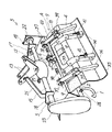
【図2】一部断面した、ロータリ耕耘具全体の斜視図である。
【図3】カバー廻りの、全体平面図である。
【図4】要部別図例の、断面側面図である。
【図5】弾性板体の、さらなる別図例である。
【符号の説明】
1 耕耘刃
2 耕耘パイプ
3 主カバー
4 リヤーカバー
5 ロータリ耕耘具
6 揺動支持部
7 メインロッド
8 弾性板体
9 リブ状肉厚部[0001]
TECHNICAL FIELD OF THE INVENTION
The present invention relates to a rear cover connection support device for a rotary tillage implement.
BACKGROUND OF THE INVENTION 1. Field of the Invention The present invention relates to a rear cover connecting and supporting device, and more particularly to a device for supporting a rear cover attached to the rear of a rotary till so as to maintain a leveling performance with respect to a main cover covering the upper portion of the rotary tillage.
[0002]
2. Related Art and Problems to be Solved by the Invention
In the conventional rotary tilling, the rear cover is attached to the main cover that covers the upper part of the tilling via the left and right shafts that are hinges. When the earth mass collides, the entire rear cover escapes to the rear, and when the collision repeatedly moves the rear cover in the front-rear direction, the rear edge of the rear cover repeats up and down on the ground surface, and the unevenness in the pitching direction on the ground surface. And the leveling performance was apt to decrease. In addition, the one having the axis in the left and right direction is close to the rigid body through the axis in the rolling direction. There was a problem that a step was formed on the surface of the part.
[0003]
In order to solve these problems, a type of connecting the main cover and the rear cover via a rubber plate has appeared, but if the rubber plate part is soft, the rear cover will escape lightly up and down and left and right, improving the leveling performance To do so, it was necessary to make the rear cover heavier.
[0004]
[Means for Solving the Problems]
The present invention is to solve such a problem of the conventional device, and has taken the following technical measures. That is, a plurality of tilling blades 1, 1,. . . The cover over the tillage pipe 2 in the main cover 3 attached, the link in the rotary tilling device 5 comprising a rear cover 4 at a distance A to the rear portion of the main cover 3, the rear right and left central portion of the main cover 3 balls equation pivot support portion 6 is provided, projecting the main rod 7 which diverts the upward to bypass the rear end of the spacing a from the support 6 to the bifurcated rearwardly, the main rod 7 the rear cover 4 to the right and left projecting end with swing freely attach the attaching a wide elastic plate member 8 in the interval a of the front and rear direction between the main cover 3 and the rear cover 4, further, the wide elastic plate Rib-shaped thick portions 9, 9 protruding upward and forward in the front-rear direction on the left and right sides and the center of the body 8; . And a rear cover connecting and supporting device for a rotary tilling tool.
[0005]
【Example】
The example of the figure is a rotary tilling tool 5 which is attached to the rear of the body 10 of an agricultural tractor so as to be able to ascend and descend and excavates and runs on the soil surface. The main cover 3 and the rear cover 4 cover the upper and rear portions of the rotary tilling tool 5. Then, the present invention is folded.
The rotary tilling tool 5 pivotally supports the front end of the top link 12 at a center hitch 11 in the left-right direction, which is fixed above the rear end of the body 10 of the agricultural tractor. The front end is pivoted. Further, the front ends of the lower links 14, 14 are pivotally supported at the right and left rear ends of the body 10 of the tractor. At the rear end of the lower link 14, support plates 18, 18 are fixedly mounted on left and right beams 16, 17 projecting left and right from a transmission case 15 near the center in the left and right direction. In addition, lower end portions of the left and right lift rods 19 are attached to the lower links 14, 14 in the middle in the front-rear direction. The upper ends of the left and right lift rods 19, 19 are attached to the protruding rear ends of left and right lift arms 20, 20 provided above the rear part of the body 10, and by rotating the lift arm 20 up and down, the rotary arm is rotated. The tiller 5 can be raised and lowered.
[0006]
A mast 13 is pivotally supported on the transmission case 15 near the center, and the middle part of the mast 13 and the support plates 18 are reinforced and connected by left and right reinforcement links 21 and 21.
A side plate 22 is fixed to the right end of the beam 17 and a side transmission case 23 is fixed to the left end of the beam 16. Between the side plate 22 and the lower end of the side transmission case 23, a tilling pipe 2 is suspended in the left-right direction, and tilling blades 1, 1,. . For attaching the nail holders 24, 24. . Are welded.
[0007]
The tilling pipe 2 is driven by the rotational force transmitted from the PTO shaft 25 projecting from the rear end of the body 10 of the agricultural tractor to the input shaft 27 of the transmission case 15 near the center via the universal joint 26. Although not shown, the driving force input from the input shaft 27 is transmitted from the transmission shaft in the left beam 16 to the upper sprocket in the side transmission case 23 via the bevel gear, and from the upper sprocket to the lower tilling pipe via a chain. This is a normal drive transmission for driving the lower sprocket at the two side ends. With the rotation of the tilling pipe 2, the tilling blades 1, 1,. . The tilling blade rotating in the direction of arrow "a" to prevent the tilling soil from scattering upward due to excavation. . . . The main cover 3 covers the upper part of the rotation locus at the tip of the head. In addition, a rear cover 4 that covers the rear with an interval A from the main cover 3 is provided. In the space A, a wide elastic plate body 8 having substantially the same width as the main cover 3 and the rear cover 4 is provided. The rear end of the main cover 3 and the front end of the rear cover 4 are respectively provided at the upper and lower ends thereof. , Which are integrally attached to the rotating tilling blades 1, 1,. . . It covers the whole from the top to the rear.
[0008]
The elastic plate body 8 is made of a wide and deformable material such as a rubber material or a resin material. Excavated mud that sometimes scatters hits the rear cover 4, and the vertical movement, right and left movement and twisting movement of the rear cover 4 due to the unevenness of the excavated mud caused by the advancement of the agricultural tractor body 10 are not so much restricted, and the position fluctuation of the rear cover 4 is not changed. It becomes intense. In the illustrated example, the elastic plate 8 has rib-shaped thick portions 9, 9,. . Are provided. The movement of the rear cover 4 can be restricted by changing the thickness and width of the rib-shaped thick portion 9.
[0009]
The rib-shaped thick portion 9 shown in FIGS. 1 to 3 is simply made of the same elastic material as the elastic plate body 8, but as shown in the cross-sectional view of FIG. The leaf spring 28 may be integrally provided by baking or the like. By doing so, the surface of the leaf spring 28 is protected from rust, abrasion and the like with a rubber material or the like, and the movement regulation of the rear cover 4 is also increased. 29, 29. . Is a mounting hole, which is used for strong fixing at the time of mounting on the front and rear main cover 3 and the rear cover 4.
[0010]
On the upper surface of the rear end of the main cover 3, a pair of central fittings 31 is protrudingly provided at the center in the left-right direction. A front end portion of a main rod 7 having a swing support portion 6 that can swing freely is attached by a shaft 32. The main rod 8 is integrally attached to a front part of a branch rod 33 whose rear end is branched into two branches. Bolts are attached to main frames 34, 34 provided on the rear cover 4 with the rear end side of the branch rod 33 in the vertical direction. , Nuts or welding.
[0011]
The rear cover 4 is a thin plate made of an iron plate, is suspended over the entire width of about 2 m of the rotary tilling tool 5, and has a rear end portion of the rear cover 4 turned into a bag-like shape as a grounding surface 35 during pressurization. The strength in the left and right direction is maintained. The strength of the rear cover 4 in the front-rear direction is maintained by the main frames 34, 34 and the sub-frames 36, 36 provided vertically at the left and right ends of the rear cover 4. Each of the main frame 34 and the sub-frame 36 is a thin iron plate having a U-shaped lower opening, and is a reinforcing frame in which the opening side is welded and integrated along the upper surface of the rear cover 4.
[0012]
In addition, on the upper surface of the rear end portion of the main cover 3, side brackets 37, 37 are respectively provided near the left and right side ends, and left and right upper stays 38, 38 are protruded substantially symmetrically inwardly. I have. The above-mentioned sub-frame 36 is located at the rear cover 4 corresponding to the rear of the side bracket 37, and a tension rod 40 is provided between the side bracket 39 and the side bracket 37 provided at the front end of the sub-frame 36. , 40. The front and rear ends of the tension rod 40 are pivotally supported by lateral pins. At this pin portion, the rear cover 4 is swingable in the vertical direction, thereby restricting a large movement of the rear cover 4. If the rib-shaped thick portion 9 of the main part is strengthened, the tension rod 40 can be eliminated.
[0013]
As shown in FIG. 1, the upper stay 38 has a push-pull rod 42 attached to a lower stay 41 provided on the upper surface of the main frame 34, respectively. The lower limit of rocking and the pressing force at the time of upward movement are adjusted. More specifically, the legs 44, 44 of the top 43 are supported at the distal end of a stay 38 projecting rearward from the main cover 3 integrally. The upper part of the pull rod 42 is attached in a penetrating manner. An upper lock 46 is attached to the upper end of the protrusion via a pressing spring 45, and the lower end of the push-pull rod 42 is axially mounted on the lower stay 41 with a pin. Further, a plurality of locking grooves are provided in the longitudinal direction of the push-pull rod 42. When the stopper 47 is pushed into the locking groove and the push-pull rod 42 is fixed to the top 43, the vertical movement of the rear cover 4 is fixed. When the stopper 47 is released, the push-pull rod 42 is supported by the legs 44 while freely moving in the vertical through hole of the top 43 in accordance with the vertical movement of the rear cover 4. A lower pressing spring 48 and a lower locking tool 49 are attached to the outer periphery of the push-pull rod 42 below the top 43, and the position where the lower end of the lower pressing spring 48 is pressed against the top 43 can be slid by the lower locking tool 49. Thereby, the ground pressure of the rear cover 4 can be adjusted to the pressure side. When the fixed position of the upper locking tool 46 is slid downward on the outer periphery of the push-pull rod 42, the lower limit position of the rear cover 4 when the rotary tilling tool 5 is lifted can be changed and adjusted to a high position.
[0014]
FIG. 5 shows another embodiment of the elastic plate for connecting the space A between the main cover 3 and the rear cover 4, and only different points from the above-described first embodiment will be described.
A hard elastic plate 50 made of a hard rubber or resin plate or the like is attached to the interval A to restrict the movement of the rear cover 4a to some extent. However, since the upper portion of the interval A is open, the rotary tiller is used. As the rear cover 4a moves up and down with respect to the main cover 3a when lifting and lowering the 5a, the hard elastic plate 50 can easily move up and down as a whole. When the hard elastic plate 50 is directly extended to the front lower part of the rear cover 4 and the back portion is attached to the rear cover 4 with a smaller mounting pitch, the hard elastic plate 50 is hard and is hardly deformed. , 1. . Scattered mud excavated at the site easily adheres to the surface.
[0015]
Therefore, in this alternative embodiment, a rubber or resin plate extending downward and forward of the rear cover is attached to the rear cover 4 with a predetermined space opened in the back, and a soft elastic member having a hardness of about half of that of the hard elastic plate 50 is attached. The elastic plate 51 is used.
In the illustrated example, the front edge of the hard elastic plate 50 is connected to the fasteners 52, 52. . At the rear end of the main cover 3a, the rear end of the hard elastic plate 50 is projected from the rear cover 4a. . Installed with A front edge portion of the soft elastic plate 51 is attached to a rear portion of the lower surface of the L fitting 53. The rear edge of the hard elastic plate 50 and the front edge of the soft elastic plate 51 are simultaneously attached to the L bracket 53 via the holding plate 55.
[0016]
A plurality of supporting bosses 56, 56. . . , A space is provided between the rear cover 4a and the fasteners 57, 57. . Installed with Due to the space and the softness of the hardness, the excavated mud struck against the surface of the soft elastic plate 51 is softly received, so that the mud adhered to the surface of the soft elastic plate 51 is reduced.
[0017]
In the illustrated example, the hard elastic plate 50 and the soft elastic plate 51 are two separate members, but the same effect can be obtained by changing the hardness before and after with one elastic plate.
[0018]
Operation and Effect of the Invention
The present invention is intended to solve such a problem of the conventional device, and has taken the following technical measures. That is, a plurality of tilling blades 1, 1,. . . The cover over the tillage pipe 2 in the main cover 3 attached, the link in the rotary tilling device 5 comprising a rear cover 4 at a distance A to the rear portion of the main cover 3, the rear right and left central portion of the main cover 3 balls equation pivot support portion 6 is provided, projecting the main rod 7 which diverts the upward to bypass the rear end of the spacing a from the support 6 to the bifurcated rearwardly, the main rod 7 the rear cover 4 to the right and left projecting end with swing freely attach the attaching a wide elastic plate member 8 in the interval a of the front and rear direction between the main cover 3 and the rear cover 4, further, the wide elastic plate Rib-shaped thick portions 9, 9 protruding upward and forward in the front-rear direction on the left and right sides and the center of the body 8; . , The rear cover 4 has good followability even when the rear cover 4 is moved in the pitching and rolling directions or in the direction of twisting due to unevenness of the ground surface. In the case of excessive movement, the rib-shaped thick portions 9, 9 provided on the left and right sides and the center of the elastic plate 8 and projecting upward in the front-rear direction. . This movement is regulated, so the leveling performance is good .
[Brief description of the drawings]
FIG. 1 is an overall side view in which a tilling tool having a cross section of a rear cover portion is attached to a rear portion of the machine.
FIG. 2 is a perspective view of the whole rotary tilling tool, partially sectioned.
FIG. 3 is an overall plan view around a cover.
FIG. 4 is a cross-sectional side view of an example of a drawing for different main parts.
FIG. 5 is another example of the elastic plate body.
[Explanation of symbols]
DESCRIPTION OF SYMBOLS 1 Tilling blade 2 Tillage pipe 3 Main cover 4 Rear cover 5 Rotary tillage tool 6 Swing support part 7 Main rod 8 Elastic plate 9 Rib thick part