JP3570553B2 - Torque transmission device - Google Patents
Torque transmission device Download PDFInfo
- Publication number
- JP3570553B2 JP3570553B2 JP2001354702A JP2001354702A JP3570553B2 JP 3570553 B2 JP3570553 B2 JP 3570553B2 JP 2001354702 A JP2001354702 A JP 2001354702A JP 2001354702 A JP2001354702 A JP 2001354702A JP 3570553 B2 JP3570553 B2 JP 3570553B2
- Authority
- JP
- Japan
- Prior art keywords
- torque
- turbine
- transmission
- transmission shaft
- impeller
- Prior art date
- Legal status (The legal status is an assumption and is not a legal conclusion. Google has not performed a legal analysis and makes no representation as to the accuracy of the status listed.)
- Expired - Fee Related
Links
Images


Classifications
-
- F—MECHANICAL ENGINEERING; LIGHTING; HEATING; WEAPONS; BLASTING
- F16—ENGINEERING ELEMENTS AND UNITS; GENERAL MEASURES FOR PRODUCING AND MAINTAINING EFFECTIVE FUNCTIONING OF MACHINES OR INSTALLATIONS; THERMAL INSULATION IN GENERAL
- F16H—GEARING
- F16H41/00—Rotary fluid gearing of the hydrokinetic type
- F16H41/24—Details
- F16H2041/246—Details relating to one way clutch of the stator
-
- F—MECHANICAL ENGINEERING; LIGHTING; HEATING; WEAPONS; BLASTING
- F16—ENGINEERING ELEMENTS AND UNITS; GENERAL MEASURES FOR PRODUCING AND MAINTAINING EFFECTIVE FUNCTIONING OF MACHINES OR INSTALLATIONS; THERMAL INSULATION IN GENERAL
- F16H—GEARING
- F16H45/00—Combinations of fluid gearings for conveying rotary motion with couplings or clutches
- F16H45/02—Combinations of fluid gearings for conveying rotary motion with couplings or clutches with mechanical clutches for bridging a fluid gearing of the hydrokinetic type
- F16H2045/021—Combinations of fluid gearings for conveying rotary motion with couplings or clutches with mechanical clutches for bridging a fluid gearing of the hydrokinetic type three chamber system, i.e. comprising a separated, closed chamber specially adapted for actuating a lock-up clutch
-
- F—MECHANICAL ENGINEERING; LIGHTING; HEATING; WEAPONS; BLASTING
- F16—ENGINEERING ELEMENTS AND UNITS; GENERAL MEASURES FOR PRODUCING AND MAINTAINING EFFECTIVE FUNCTIONING OF MACHINES OR INSTALLATIONS; THERMAL INSULATION IN GENERAL
- F16H—GEARING
- F16H45/00—Combinations of fluid gearings for conveying rotary motion with couplings or clutches
- F16H45/02—Combinations of fluid gearings for conveying rotary motion with couplings or clutches with mechanical clutches for bridging a fluid gearing of the hydrokinetic type
- F16H2045/0273—Combinations of fluid gearings for conveying rotary motion with couplings or clutches with mechanical clutches for bridging a fluid gearing of the hydrokinetic type characterised by the type of the friction surface of the lock-up clutch
- F16H2045/0284—Multiple disk type lock-up clutch
-
- F—MECHANICAL ENGINEERING; LIGHTING; HEATING; WEAPONS; BLASTING
- F16—ENGINEERING ELEMENTS AND UNITS; GENERAL MEASURES FOR PRODUCING AND MAINTAINING EFFECTIVE FUNCTIONING OF MACHINES OR INSTALLATIONS; THERMAL INSULATION IN GENERAL
- F16H—GEARING
- F16H45/00—Combinations of fluid gearings for conveying rotary motion with couplings or clutches
- F16H45/02—Combinations of fluid gearings for conveying rotary motion with couplings or clutches with mechanical clutches for bridging a fluid gearing of the hydrokinetic type
-
- Y—GENERAL TAGGING OF NEW TECHNOLOGICAL DEVELOPMENTS; GENERAL TAGGING OF CROSS-SECTIONAL TECHNOLOGIES SPANNING OVER SEVERAL SECTIONS OF THE IPC; TECHNICAL SUBJECTS COVERED BY FORMER USPC CROSS-REFERENCE ART COLLECTIONS [XRACs] AND DIGESTS
- Y02—TECHNOLOGIES OR APPLICATIONS FOR MITIGATION OR ADAPTATION AGAINST CLIMATE CHANGE
- Y02T—CLIMATE CHANGE MITIGATION TECHNOLOGIES RELATED TO TRANSPORTATION
- Y02T10/00—Road transport of goods or passengers
- Y02T10/60—Other road transportation technologies with climate change mitigation effect
- Y02T10/62—Hybrid vehicles
Description
【0001】
【発明の属する技術分野】
本発明は、エンジンの出力トルクを変速機に伝達するためのトルク伝達装置に関する。
【0002】
【従来の技術】
近年、自動車の燃費向上を図る技術の1つとして、エンジンの出力トルクを変速機に伝達するためのトルク伝達系にモータジェネレータを配置して、走行時の制動エネルギを電力として取り出す回生を行ったり、バッテリに充電された電気をモータジェネレータの出力トルクによりエンジントルクをアシストする等の技術が提案されている。
【0003】
このようなトルク伝達系の構成として、エンジンとトルクコンバータとの間にモータジェネレータを配置したものがある。トルクコンバータは、エンジンの出力トルクが入力されるインペラと、インペラに対向して配置され変速機にトルクを出力するタービンと、インペラとタービンとの間に配置されタービンからインペラへの流体の流れを整流するための整流ステータとを有するものである。このトルク伝達系の構成では、制動回生時に、変速機側のトルクがトルクコンバータを介して伝達されるため、トルクコンバータにおける制動分だけモータジェネレータにおけるエネルギの回生量が減少することになる。
【0004】
これに対して、例えば、特開2000−287303号公報に記載の技術のように、トルクコンバータがエンジンとモータジェネレータとの間に配置された構成を有するものがある。
このような構成においては、モータジェネレータがトルクコンバータよりも変速機側に配置されているため、制動回生時においても、変速機のトルクが直接モータジェネレータに伝達される。これにより、モータジェネレータでエネルギ回生がされ易くなる。すなわち、この構成におけるエネルギ回生量は、エンジンとトルクコンバータとの間にモータジェネレータを配置した構成におけるエネルギ回生量よりも増加するようになる。
【0005】
【発明が解決しようとする課題】
しかし、上記のトルク伝達系の構成においては、トルクコンバータと変速機との間にモータジェネレータが配置されているため、トルクコンバータの整流ステータをステータ固定軸を介して変速機のミッションケースに固定する等の通常の固定方法を採用できない。このため、本トルク伝達系を具体的に構成する際には、整流ステータの固定方法が問題となる。
【0006】
この問題を解決するために、特開2000−287303号公報に記載の技術では、トルクコンバータ及びモータジェネレータを収納する外側ハウジングに固定された内側ハウジングをトルクコンバータとモータジェネレータの軸方向間に設け、この内側ハウジングに整流ステータのステータ固定軸が固定される構成を採用している。すなわち、上記トルク伝達系では、トルクコンバータとモータジェネレータの軸方向間に別部材を設けて、さらに、この別部材をトルクコンバータ及びモータジェネレータを収納する外側ハウジングに固定している。これにより、整流ステータを固定するという目的は達成されるが、トルク伝達系の軸方向及び半径方向のサイズが増加するという問題が生じる。
【0007】
本発明の課題は、モータジェネレータがトルクコンバータよりも変速機側に配置されたトルク伝達系の構成において、コンパクトなトルク伝達装置を提供することにある。
【0008】
【課題を解決するための手段】
請求項1に記載のトルク伝達装置は、エンジンの出力トルクを変速機に伝達するためのトルク伝達装置であって、変速機にトルクを出力する伝達軸と、トルクコンバータと、入力軸との間でトルクを授受可能なモータジェネレータと、遊星歯車装置とを備えている。トルクコンバータは、エンジンの出力トルクが入力されるインペラと、インペラに対向して配置され伝達軸にトルクを出力するタービンと、インペラとタービンとの間に配置されタービンからインペラへの作動油の流れを整流するための整流ステータとを有している。モータジェネレータは、伝達軸に装着されたロータとロータに対向して配置されたステータとを有している。遊星歯車装置は、伝達軸に設けられたサンギアと、サンギアの外周側に配置されサンギアと噛み合う複数のプラネタリギアと、ロータが装着されプラネタリギアと噛み合うリングギアと、整流ステータが装着され複数のプラネタリギアを軸支する遊星キャリアとを有している。
【0009】
このトルク伝達装置では、トルクコンバータの整流ステータが遊星歯車装置を構成する遊星キャリアに固定されている。そして、モータジェネレータのトルクの伝達軸との入出力は、モータジェネレータのロータが装着されたリングギアと伝達軸に形成されたサンギアとの間で、プラネタリギアを介して行われる。遊星歯車装置は、軸方向及び半径方向の寸法を増加させることなく配置することができるため、従来のように整流ステータをトルクコンバータとモータジェネレータの軸方向間に別部材を設けて外側ハウジングに固定する必要がなく、コンパクトなトルク伝達装置を実現できる。
【0010】
請求項2に記載のトルク伝達装置では、請求項1において、インペラ、整流ステータ及びタービンは、トーラスを形成している。そして、トーラスは、半径方向寸法Hに対する軸方向寸法Lの比である扁平率L/Hが0.7以下である。
このトルク伝達装置では、トーラスの扁平率が0.7以下のトルクコンバータを使用しているので、トルク伝達系の軸方向寸法の短縮化が可能である。
【0011】
請求項3に記載のトルク伝達装置は、請求項1又は2において、タービンは伝達軸に対してその反回転方向にのみ相対回転可能となるように伝達軸に装着されている。
このトルク伝達装置では、トルクコンバータのタービンが伝達軸に対してその反回転方向にのみ相対回転可能となるように変速機の伝達軸に装着されているため、トルクコンバータのタービンの回転数が変速機の伝達軸の回転数よりも相対的に大きい場合は、タービンと伝達軸とが一体となって回転し、タービンから伝達軸へトルクが伝達する。逆に、タービンの回転速度が伝達軸の回転速度よりも小さい場合は、タービンが伝達軸の回転方向と逆方向に相対回転し、伝達軸からトルクコンバータへトルクが伝達しないようになっている。これにより、トルクコンバータを経由してエンジン部分で吸収されるトルクによる制動を抑えて、モータジェネレータによるエネルギ回生の効率を向上させることができる。
【0012】
請求項4に記載のトルク伝達装置では、請求項1〜3のいずれかにおいて、トルクコンバータは、インペラ、整流ステータ及びタービンを介さずにエンジンから入力されるトルクを出力側に出力するためのロックアップ装置をさらに備えている。
このトルク伝達装置は、ロックアップ装置を作動した際に、トルクコンバータを構成するフロントカバーと、ロックアップ装置を構成するダンパー機構と、モータジェネレータのロータとが伝達軸上に直列に並んだ構成となる。この構成においては、ロックアップ装置のダンパー機構の下流側に大きな慣性モーメントを有するロータがあるため、2つのフライホイールの間にダンパー機構が配置された振動系と類似の振動系を形成する。これにより、トルク伝達系の共振点が低回転数側にシフトして、エンジン回転数の変動の伝達軸への伝達を減衰させることができる。
【0013】
請求項5に記載のトルク伝達装置では、請求項4において、ロックアップ装置は、インペラ、整流ステータ及びタービンの作動油系統とは別の作動油系統から供給される油圧によって作動される別室式のクラッチ機構を備えたものである。このトルク伝達装置では、別室式のクラッチ機構を備えているため、ロックアップ動作の応答性が向上している。ここで、別室式のクラッチ機構とは、インペラ、タービン及び整流ステータの作動油系統とは別の作動油系統の油圧によって操作され、インペラ、タービン及び整流ステータ側の作動油がクラッチ機構の操作に影響されにくい構造を有するものである。
【0014】
【発明の実施の形態】
第1実施形態
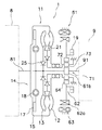
本発明の第1実施形態にかかるトルク伝達装置1の模式図を図1に示す。
[構成]
図1に示すトルク伝達装置1は、エンジン8の出力軸81と、変速機9との間に配置されている。
【0015】
エンジン8はガソリン等を燃焼させて動力を得るための内燃機関であり、このエンジン8のクランク軸(図示せず)から出力されるトルクがエンジン出力軸81を介してエンジン8の側面に装着されたトルク伝達装置1に出力される。変速機9は、自動変速機又は無段変速機であり、トルク伝達装置1から出力されたトルクが入力される。
【0016】
トルク伝達装置1は、エンジン8の出力軸81からのトルクを変速機9へ伝達するための装置であり、トルクコンバータ11と、伝達軸91との間でトルクを授受可能なモータジェネレータ61と、伝達軸91のトルクとモータジェネレータ61とを連結するための遊星歯車装置71とを備えている。
トルクコンバータ11は、エンジン8の出力トルクが入力されるインペラ12と、インペラ12に対向して配置され伝達軸91にトルクを出力するタービン13と、インペラ12とタービン13との間に配置されタービン13からインペラ12への作動油の流れを整流するための整流ステータ21と、ロックアップ装置14とを備えている。
【0017】
次に、図2を用いてトルク伝達装置1の詳細を説明する。図2は、本実施形態のトルク伝達装置1の縦断面概略図である。図2の左側に図示しないエンジン8が配置され、図2の右側に図示しない変速機9が配置されている。また、図2に示すO−Oがトルクコンバータ11、モータジェネレータ61及び遊星歯車装置71の回転軸である。
【0018】
(a)トルクコンバータ
トルクコンバータ11は、主に、3種の羽根車(インペラ12、タービン13、整流ステータ21)からなるトーラス20を有するトルクコンバータ本体と、ロックアップ装置14とから構成されている。
フロントカバー15は、円板状の部材であり、最も軸方向エンジン8側に配置されている。フロントカバー15の内周部には、センターボス22が固定されている。センターボス22は、軸方向に延びる円柱形状の部材であり、図示しないクランクシャフトの中心孔に挿入されている。フロントカバー15の最外周部には、円周方向に複数のナット23が固定されている。このナット23に対して、図示しない例えばフレキシブルプレートの外周部がボルトによって固定されている。フロントカバー15の外周部には、軸方向変速機9側に延びる外周筒状部15aが形成されている。この外周筒状部15aの内周面には、軸方向に延びる複数の歯15bが円周方向に並んで形成されている。また、外周筒状部15aの軸方向変速機9側先端には、インペラ12のインペラーシェル12aの外周縁が固定されている。この結果、フロントカバー15と外周筒状部15aとインペラ12とによって、内部に作動油が充填された流体作動室を形成している。
【0019】
インペラ12は、フロントカバー15と一体に固定された部材であり、インペラーシェル12aと、インペラーシェル12aの内側に固定された複数のインペラーブレート12bとから主に構成されている。
タービン13は、流体作動室内でインペラ12に対向して配置されている。タービン13は、タービンシェル13aと、タービンシェル13aのインペラ12側の面に固定された複数のタービンブレード13bと、タービンシェル13aを伝達軸91に固定するためのタービンハブ13cとから主に構成されている。タービンシェル13aの内周部は、タービンハブ13cの半径方向中間部分に複数のリベット24によって、後述のダンパー機構18を構成するドリブンプレート40の内周部とともに固定されている。なお、タービンハブ13cの内周面は、伝達軸91にスプライン係合して相対回転不能になっている。タービンハブ13cの軸方向エンジン8側の外周部には、フロントカバー15の内面に接するように円板状部材26が配置されている。円板状部材26の内周端は、タービンハブ13cの外周部に回転可能に支持され、フロントカバー15及びセンターボス22と一体に回転する。円板状部材26のフロントカバー15に接する面には、放射状に延びる油路26a、26bが形成されている。これにより、フロントカバー15とタービン13との間の空間は、軸方向に分割されている。さらに、フロントカバー15とタービンハブ13cとの軸方向間には、スラストワッシャ27が配置されている。スラストワッシャ27がフロントカバー15及びタービンハブ13cに接する面には、放射状に延びる油路が形成されている。
【0020】
整流ステータ21は、タービン13からインペラ12へと戻る作動油の流れを整流するための機構である。整流ステータ21は、樹脂やアルミ合金等により鋳造によって製造された一体の部材である。整流ステータ21はインペラ12の内周部とタービン13の内周部との軸方向間に配置されている。整流ステータ21は、主に、環状のステータキャリア21aと、ステータキャリア21aの外周面に設けられた複数のステータブレード21bとから構成されている。ステータキャリア21aは、ワンウェイクラッチ25を介して、後述の遊星歯車装置71の遊星キャリア72に支持されている。タービンハブ13cの内周部とワンウェイクラッチ25との軸方向間には、第1スラストベアリング28が配置されている。第1スラストベアリング28には、半径方向に貫通する複数の溝が形成されている。ステータキャリア21aとインペラーシェル12aの内周部との軸方向間には、第2スラストベアリング29が配置されている。ステータキャリア21aの第2スラストベアリング29側には、半径方向に貫通する複数の溝が形成されている。
【0021】
ここで、インペラ12、タービン13及び整流ステータ21により構成されるトーラス20は、扁平率が小さいものを使用している。具体的には、トーラス20の半径方向寸法Hと軸方向寸法Lとの比L/Hが0.7以下のものである。ここで、半径方向寸法Hは整流ステータ21のステータキャリア21aの最も半径方向外側の部分とインペラ12の内側で半径方向外側の部分との間の距離をいい、軸方向寸法Lはインペラ12の内側で軸方向変速機9側の部分とタービン13の内側で軸方向エンジン8側の部分との間の距離をいう。
【0022】
次に、ロックアップ装置14について説明する。ロックアップ装置14は、運転の必要に応じてフロントカバー15と伝達軸91との間を機械的に連結するための装置であり、クラッチ機構17とダンパー機構18とから主に構成されている。
クラッチ機構17は、フロントカバー15から直接タービン13に対してトルクを伝達可能とするための機構である。クラッチ機構17は、主に、フロントカバー15の外周筒状部15aと、ダンパー機構18を構成する第1ドライブプレート31と、クラッチプレート32、33、34と、ピストン35とから構成されている。クラッチプレート32、34は、外周縁に外周筒状部15aの歯15bに係合する外周歯を有している。これにより、クラッチプレート32、34は、フロントカバー15と一体回転するように、かつ、軸方向に相対移動可能になっている。クラッチプレート33は、クラッチプレート32とクラッチプレート34との軸方向間に配置されている。クラッチプレート33の内周縁には複数の歯が形成されている。また、クラッチプレート33の軸方向両面には摩擦フェーシングが貼られている。第1ドライブプレート31の外周面には軸方向に延びる複数の歯が円周方向に並んで形成されている。この第1ドライブプレート31の歯にクラッチプレート33の歯が係合している。これにより、クラッチプレート33は、第1ドライブプレート31と一体回転するように、かつ、軸方向に相対移動するようになっている。外周筒状部15aの内周縁の軸方向変速機9側には、スナップリング36が装着されている。スナップリング36は、クラッチプレート34等の軸方向変速機9側への移動を制限するための部材である。
【0023】
ピストン35は、環状の部材である。ピストン35は、フロントカバー15の軸方向変速機9側に近接して配置されている。ピストン35の外周面は、フロントカバー15の外周側に形成された内周面に当接して半径方向に支持され、軸方向及び回転方向には相対移動可能になっている。ピストン35の外周面には、環状のシール部材が装着されている。このシール部材は、前記の内周面に当接し、その軸方向両側間の作動油の流れを遮断している。ピストン35の内周面は、円板状部材26の外周面に当接し支持されている。円板状部材26の外周面には環状のシール部材が装着されている。このシール部材は、ピストン35の内周面に当接し、その軸方向両側間の作動油の流れを遮断している。また、ピストン35の外周側部分はクラッチプレート32に近接して配置されている。ピストン35は、ピストン35とフロントカバー15との間に形成された油圧室A内の油圧変化によって軸方向に移動する構成となっている。この油圧室Aは、円板状部材26の油路26a、26bを介して伝達軸91の軸中心を貫通する油孔91aに連通している。これにより、クラッチ機構17を作動させるための作動油系統は、トーラス20を作動するための作動油系統とは別の独立した油圧系統となっている。
【0024】
ダンパー機構18は、第1ドライブプレート31と、第2ドライブプレート37と、タービンハブ13cと、複数のトーションスプリング38とから構成されている。ドライブプレート31、37は環状の部材であり、外周部は互いに固定され、それより内周側の部分は軸方向に間隔をあけて配置されている。ドライブプレート31、37の外周部は、複数のリベット39により一体となるように固定されている。また、ドライブプレート31、37の内周側部分には、軸方向に切り起こされたばね支持部31a、37aが形成されている。ドライブプレート31、37の軸方向間には、ドリブンプレート40が配置されている。そして、ドリブンプレート40の内周部は、リベット24によってタービンハブ13cに固定されている。ドリブンプレート40の外周部においてばね支持部31a、37aに対応する部分には、窓孔40aが形成されている。トーションスプリング38は、窓孔40a内及びばね支持部31a、37a内に配置された部材であり、ドライブプレート31、37からドリブンプレート40を介してタービンハブ13cにトルクを伝達すると共に捩り振動を吸収・減衰するための部材である。トーションスプリング38は、円周方向に弧状又は直線状に延びるコイルスプリングからなる。トーションスプリング38の円周方向両端は、窓孔40a及びばね支持部31a、37aの円周方向両端に支持されている。また、トーションスプリング38の軸方向両側は、ばね支持部31a、37aによって支持されている。
【0025】
ここで、トルクコンバータ11に供給される作動油は、伝達軸91の回転によって駆動されるオイルポンプ19によって供給されるようになっている。このオイルポンプ19は、後述のモータジェネレータ61のロータ62と伝達軸91との結合部付近に配置されている。
(b)モータジェネレータ
モータジェネレータ61は、トルクコンバータ11の変速機9側に配置され、伝達軸91に遊星歯車装置71を介して装着されたロータ62とロータ62に対向して配置されたステータ63とを備えている。
【0026】
ロータ62の外周側には、永久磁石からなるロータマグネット62aが備えられている。ロータ62の内周部には、リングギア64がリベット65を介して固定されており、後述の遊星歯車装置71の一部を構成している。
ステータ63は、トルク伝達装置1の最外周側に配置されたコイルが巻き付けられた部材であり、バッテリ(図示せず)に接続され、電気の授受を行っている。
【0027】
(c)遊星歯車装置
遊星歯車装置71は、伝達軸91に形成されたサンギア91bと、サンギア91bに噛み合うプラネタリギア73と、プラネタリギア73に噛み合うリングギア64と、プラネタリギア73を軸支するための遊星キャリア72とから主に構成されている。
【0028】
リングギア64は、ロータ62の内周部に固定されており、サンギア91bとリングギア64との両方に噛み合うプラネタリギア73を介して、伝達軸91とロータ62との間で回転を伝達している。
遊星キャリア72は、プラネタリギア73を軸支するための部材であり、プラネタリギア73の軸方向エンジン8側に配置された環状の第1プレート部材74と、プラネタリギア73の軸方向変速機9側に配置された環状の第2プレート部材75とから主に構成されている。
【0029】
第1プレート部材74の内周部には、伝達軸91の外周部に沿って、軸方向エンジン8側に延びる第1筒状部74aが形成されている。第1筒状部74aの先端の外周部には、スプライン74bが形成されている。そして、整流ステータ21のステータキャリア21aは、スプライン74bと嵌合して回転不能に固定されている。また、第1筒状部74aの外周部とロータ62の内周部との半径方向間には、軸受76が設けられている。
【0030】
第2プレート部材75の内周部には、伝達軸91の外周部に沿って、軸方向変速機9側に延びる第2筒状部75aが形成されている。第2筒状部75aの外周部には、スプライン75bが形成されている。そして、第2筒状部75aのスプライン75bは、トルク伝達装置1の周囲を覆うハウジング3に回転不能に固定されている。
【0031】
[動作]
次に、トルク伝達装置1の動作について説明する。
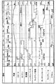
図3は運転モードとトルク伝達装置1の各部等の状態を示す表であり、図4は図3のトルク伝達装置1の各部の状態を示したタイムチャートである。図3には、トルク伝達装置1の各部等として、エンジン8、モータジェネレータ61、変速機9、ロックアップ装置14、トルクコンバータ11(以下の説明では、インペラ12、タービン13及び整流ステータ21を指す)及びエンジン8を始動するためのスタータ(図1には図示せず)が項目として列記されている。図4には、図3の項目に加えて、車両の速度、フットブレーキ及びアクセルが列記されている。以下、図3及び図4の番号に従って、トルク伝達装置1の動作を説明する。
【0032】
(1)駐車(停車)時
駐車(停車)時においては、エンジン8はオフであり、変速機9のシフトポジションはパーキング(以下、Pとする)又はニュートラル(以下、Nとする)であり、スタータ、モータジェネレータ61及びトルクコンバータ11はオフとなっている。
【0033】
(2)初回始動
エンジン8の初回始動時は、スタータをオンにして、エンジン8を始動する。ここで、エンジン8は低速回転で作動する。尚、変速機9のシフトポジションは、P又はNである(アイドリング状態)。
(3)暖機運転
エンジン8が始動されると、トルクコンバータ11は低トルク状態で作動し、暖機運転に移行する。このとき、バッテリが充電不足の場合には、モータジェネレータ61を発電モード(以下、Gモードとする)にして、伝達軸91に遊星歯車装置71を介して装着されたロータ62のトルクをステータ63との電磁作用により電気に変換してバッテリの充電を行う。逆に、バッテリの充電が十分な場合や暖機運転中に充電が完了した場合は、エンジン8を停止し、モータジェネレータ61及びトルクコンバータ11をオフにする。
【0034】
(4)発進への変速機シフトチェンジ及び発進待機
次に、変速機9のシフトポジションをP又はNの状態から前進(以下、Dとする)の状態に変更する(後進する場合はシフトポジションをRにする)。このとき、モータジェネレータ61を放電モード(以下、Mモードとする)にして、バッテリに充電した電気をロータ62の回転に変換して伝達軸91にトルクを入力する。これにより、通常、エンジンからのトルクにより発生させるクリープ状態(以下、エンジンクリープとする)をモータジェネレータ61によって発生させる(以下、モータクリープとする)。これによって、例えば、ブレーキを踏み込んだ車両停止の場面からブレーキを解除すると、その瞬間から車両を駆動する加速度を生じさせることができ、制御された車両に生じやすい応答遅れによる不快感を与えることを回避できる。
【0035】
(5)発進
次に、アクセルを踏み込んで発進する。このとき、エンジン8はオフの状態で発進する。つまり、車両は、モータジェネレータ61のみにより駆動される。そして、アクセルの踏み込み量に応じて、モータジェネレータ61から伝達軸91に入力されるトルクが増大し、徐々に車両の速度が増加する。これにより、滑らかな発進が得られる。
【0036】
(6)エンジン再始動
次に、回転数が例えば400〜500min−1になった時点で、ロックアップ装置14を作動(以下、ロックアップオンとする)させて、エンジン8の出力軸81と伝達軸91とを直結して、エンジン8を再始動する。エンジン8が再始動したら、ロックアップ装置14をロックアップオフにして、エンジン8の出力トルクがトルクコンバータ11を介して伝達軸91に伝達されるようにする。具体的には、ロックアップオンの場合は、図2において、伝達軸91の油孔91aを通じてフロントカバー15とピストン35との間の空間に作動油を供給し、ピストン35をクラッチプレート32に押し付けることによって、ダンパー機構18を介して、フロントカバー15と伝達軸91とを直結する。逆に、ロックアップオフの場合は、フロントカバー15とピストン35との間の空間の作動油を排出して、ピストン35をクラッチプレート32から離反させる。これにより、車両は、エンジン8とモータジェネレータ61とのトルクによって駆動されるようになる。このように、ロックアップ装置14は、別室式のクラッチ機構17を備えているため、上記のような一時的な動作においても、応答よくロックアップ動作を行うことができる。
【0037】
(7)加速
エンジン8が再始動した後、上記のように、伝達軸91に伝達されるトルクは、エンジン8の出力トルクとモータジェネレータ61の出力トルクの合計値となっている。そして、さらにアクセルを踏み込むことによって、エンジン8からのトルクが大きくなり、モータジェネレータ61からの入力トルクが相対的に小さくなり、エンジン8での駆動に切り替わって行く。尚、バッテリの充電量が不足してきた場合には、適時モータジェネレータ61をGモードとしてバッテリへの充電を行う。
【0038】
(8)低速走行
ある程度加速された後、車両は低速での走行を行う。このときも加速時と同様、モータジェネレータ61をオフ又はGモードにしている。
(9)変速
次に、変速機9のシフトポジションを適時変更しながら走行する。この際、モータジェネレータ61を伝達軸91の回転数の同期制御を行う。具体的には、変速機9のダウンシフト時においては、モータジェネレータ61をMモードとし伝達軸91の回転数を増加させて、エンジン8と伝達軸91との回転数を同期させた後、シフトチェンジを行うものである。逆に、アップシフト時においては、モータジェネレータ61をGモードにして、伝達軸91の回転数を下降させてエンジン8と伝達軸91との回転数を同期させた後、シフトチェンジを行う。これにより、変速時のショックを少なくできる。
【0039】
(10)高速走行
次に、車速が上昇したら、ロックアップ装置14をロックアップオンにして運転する。このとき、バッテリの充電が不足している場合は、モータジェネレータをGモードとして、エンジン8からのトルクを回生してバッテリを充電する。
(11)走行中の緩いアクセルオフ
走行中において、アクセルの踏み込みを緩めて少し速度を下降させる場合がある。この際には、ロックアップ装置14をロックアップオフにし、同時に、モータジェネレータ61はGモードにして、伝達軸91のトルクを回生する。すなわち、車両を緩やかに制動しながらエネルギ回生を行う。
【0040】
(12)走行中の急なアクセルオフ
走行中において、さらに車両を減速させるためにアクセルを全閉して、エンジン8の燃料供給を止める場合(以下、燃料カットとする。)がある。この際には、ロックアップ装置14をロックアップオンにして、エンジン8の出力軸81と伝達軸91とを直結する。このとき、モータジェネレータ61はGモードのままにして、モータジェネレータ61による回生制動を行うとともに、エンジンブレーキによる制動を行う。尚、ロックアップ装置14はロックアップオンとしているので、再加速時のエンジン8の再始動が容易な状態となっている。
【0041】
(13)ブレーキング
フットブレーキを踏み込んでブレーキングすると、エンジンブレーキ、モータジェネレータ61による回生制動及びフットブレーキによる制動がかかり、車両は急激に減速される。
(14)ブレーキオンの車両停止
車両を停止する場合、フットブレーキによりブレーキングして、車両を停止させた後、シフトポジションをN又はPにする。そして、エンジン8、トルクコンバータ11、ロックアップ装置14及びモータジェネレータ61がオフになる。
【0042】
[特徴]
本実施形態のトルク伝達装置の特徴について説明する。
(1)コンパクト化
本実施形態のトルク伝達装置1では、トルクコンバータ11の整流ステータ21が遊星歯車装置71を構成する遊星キャリア72に固定されている。そして、モータジェネレータ61のトルクの伝達軸91との入出力は、モータジェネレータ61のロータ62が装着されたリングギア64と伝達軸91に形成されたサンギア91bとの間で、プラネタリギア73を介して行われる。遊星歯車装置71は、軸方向及び半径方向の寸法を増加させることなく配置することができるため、従来のように整流ステータ21をトルクコンバータ11とモータジェネレータ61の軸方向間に別部材を設けてハウジング3に固定する必要がなく、コンパクトなトルク伝達装置を実現できる。
【0043】
また、トルク伝達装置1では、トーラス20の扁平率が0.7以下のトルクコンバータ11を使用しているので、トルク伝達系の軸方向寸法の短縮化が可能である。
(3)エンジンの回転数変動の伝達の減衰効果
本実施形態のトルク伝達装置1は、ロックアップ装置14を作動した際に、トルクコンバータ11を構成するフロントカバー15と、ロックアップ装置14を構成するダンパー機構18と、モータジェネレータ61のロータ62とが伝達軸91上に直列に並んだ構成となる。この構成においては、ロックアップ装置14のダンパー機構18の下流側に大きな慣性モーメントを有するロータ62があるため、2つのフライホイールの間にダンパー機構が配置された振動系と類似の振動系を形成する。これにより、トルク伝達系の共振点が低回転数側にシフトして、エンジン回転数の変動の伝達軸への伝達を減衰させることができる。
【0044】
(4)発進時にモータジェネレータのみで駆動することによる燃費向上
本実施形態のトルク伝達装置1は、発進時にモータジェネレータ61のトルクのみで車両を駆動することができるため、燃費の向上に寄与できる。
(5)変速ショックの低減
本実施形態のトルク伝達装置1は、変速機9のシフト変更の際、モータジェネレータ61を伝達軸91の回転数の同期制御を行っている。具体的には、変速機9のダウンシフト時においては、モータジェネレータ61をMモードにして、伝達軸91の回転数を上昇させてエンジン8と伝達軸91との回転数を同期させた後、シフトチェンジを行う。逆に、アップシフト時においては、モータジェネレータ61をGモードにして、伝達軸91の回転数を下降させてエンジン8と伝達軸91との回転数を同期させた後、シフトチェンジを行う。これにより、変速ショックを少なくできる。
【0045】
第2実施形態
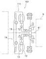
本発明の第1実施形態にかかるトルク伝達装置101の模式図を図7に示す。
[構成]
図7に示すトルク伝達装置101は、図1の第1実施形態に示されるトルク伝達装置1のタービン13を伝達軸91に第2ワンウェイクラッチ16を介して固定している点のみが異なる。その他については、第1実施形態と同様であるため説明を省略する。
【0046】
本実施形態のトルクコンバータ111は、エンジン8の出力トルクが入力されるインペラ12と、インペラ12に対向して配置され伝達軸91にトルクを出力するタービン13と、整流ステータ21と、ロックアップ装置14とを備えている。前述のように、タービン13は、伝達軸91に対してその反回転方向にのみ相対回転可能となるように、第2ワンウェイクラッチ16を介して、伝達軸91に装着されている。すなわち、トルクコンバータ111のタービン13の回転数が伝達軸91の回転数よりも相対的に大きい場合は、タービン13と伝達軸91とが一体となって回転し、タービン13から伝達軸91へトルクが伝達する。逆に、タービン13の回転数が伝達軸91の回転数よりも相対的に小さい場合は、タービン13が伝達軸91の回転方向と反対方向に相対回転し、伝達軸91からタービン13へトルクが伝達しないようになっている。
【0047】
[動作及び特徴]
次に、トルク伝達装置101の動作及び特徴について説明する。尚、基本的な動作及び特徴は第1実施形態と同様であるため、第2ワンウェイクラッチ16を装着したことによる相違点を中心に説明する。
図8は運転モードとトルク伝達装置101の各部等の状態を示す表であり、図9は図8のトルク伝達装置101の各部の状態を示したタイムチャートである。具体的には、図8には、トルク伝達装置101の各部等として、エンジン8、モータジェネレータ61、変速機9、ロックアップ装置14、トルクコンバータ111(以下の説明では、インペラ12、タービン13及び第2ワンウェイクラッチ16を指す)及びエンジン8を始動するためのスタータ(図1には図示せず)が項目として列記されている。図9は、図8の項目に加えて、車両の速度、フットブレーキ及びアクセルを含む各部等の状態を示すタイムチャートである。
【0048】
走行中の緩いアクセルオフ(図8及び9中の番号(11))については、トルクコンバータ111のタービン13は、第2ワンウェイクラッチ16を介して伝達軸91に装着されているので、伝達軸91からタービン13へトルクが伝達されることがなく、トルクコンバータ111での制動が生じない。これにより、モータジェネレータ61によるエネルギ回生の効率が向上する。また、トルクコンバータ111内の作動油の発熱も抑えられている。
【0049】
【発明の効果】
本発明にかかるトルク伝達装置では、モータジェネレータがトルクコンバータよりも変速機側に配置されたトルク伝達系の構成において、遊星歯車装置を用いることによって、コンパクトな構造にすることができる。
【図面の簡単な説明】
【図1】本発明の第1実施形態にかかるトルク伝達装置の模式図。
【図2】第1実施形態にかかるトルク伝達装置の縦断面概略図。
【図3】第1実施形態のトルク伝達装置の運転モードとトルク伝達装置各部の状態を示す表。
【図4】図3のトルク伝達装置の各部の状態を示したタイムチャート。
【図5】ロックアップ時のトルク伝達系の振動系を示す模式図。
【図6】ロックアップ時のエンジンの回転速度の変動の伝達を減衰させる効果を説明する図。
【図7】本発明の第2実施形態にかかるトルク伝達装置の模式図。
【図8】第2実施形態のトルク伝達装置の運転モードとトルク伝達装置各部の状態を示す表。
【図9】図8のトルク伝達装置の各部の状態を示したタイムチャート。
【符号の説明】
1、101 トルク伝達装置
8 エンジン
9 変速機
11、111 トルクコンバータ
12 インペラ
13 タービン
14 ロックアップ装置
16 第2ワンウェイクラッチ
17 クラッチ機構
21 整流ステータ
61 モータジェネレータ
62 ロータ
63 ステータ
64 リングギア
71 遊星歯車装置
72 遊星キャリア
73 プラネタリギア
91 伝達軸
91b サンギア[0001]
TECHNICAL FIELD OF THE INVENTION
The present invention relates to a torque transmission device for transmitting an output torque of an engine to a transmission.
[0002]
[Prior art]
2. Description of the Related Art In recent years, as one of the technologies for improving the fuel efficiency of automobiles, a motor generator is arranged in a torque transmission system for transmitting an output torque of an engine to a transmission, and regeneration for extracting braking energy during traveling as electric power is performed. There have been proposed techniques for assisting an engine torque with the output torque of a motor generator using electricity charged in a battery.
[0003]
As a configuration of such a torque transmission system, there is a configuration in which a motor generator is arranged between an engine and a torque converter. The torque converter includes an impeller into which the output torque of the engine is input, a turbine arranged opposite to the impeller to output torque to the transmission, and a torque converter arranged between the impeller and the turbine to control a flow of fluid from the turbine to the impeller. And a commutation stator for commutation. With this configuration of the torque transmission system, the torque on the transmission side is transmitted via the torque converter during braking regeneration, so that the amount of energy regeneration in the motor generator is reduced by the amount of braking in the torque converter.
[0004]
On the other hand, for example, there is a technology in which a torque converter is disposed between an engine and a motor generator, as in the technology described in Japanese Patent Application Laid-Open No. 2000-287303.
In such a configuration, since the motor generator is disposed closer to the transmission than the torque converter, the torque of the transmission is directly transmitted to the motor generator even during braking regeneration. This facilitates energy regeneration in the motor generator. That is, the amount of energy regeneration in this configuration is larger than that in the configuration in which the motor generator is arranged between the engine and the torque converter.
[0005]
[Problems to be solved by the invention]
However, in the configuration of the torque transmission system described above, since the motor generator is disposed between the torque converter and the transmission, the rectifying stator of the torque converter is fixed to the transmission case of the transmission via the stator fixed shaft. It is not possible to adopt a normal fixing method such as For this reason, when specifically configuring the torque transmission system, a method of fixing the rectifying stator becomes a problem.
[0006]
In order to solve this problem, in the technique described in JP-A-2000-287303, an inner housing fixed to an outer housing that houses a torque converter and a motor generator is provided between the torque converter and the motor generator in the axial direction. A configuration is employed in which the stator fixed shaft of the rectifying stator is fixed to the inner housing. That is, in the torque transmission system, another member is provided between the torque converter and the motor generator in the axial direction, and the separate member is fixed to the outer housing that houses the torque converter and the motor generator. This achieves the purpose of fixing the commutation stator, but causes a problem that the axial and radial sizes of the torque transmission system increase.
[0007]
An object of the present invention is to provide a compact torque transmission device in a configuration of a torque transmission system in which a motor generator is disposed closer to a transmission than a torque converter.
[0008]
[Means for Solving the Problems]
A torque transmission device according to
[0009]
In this torque transmission device, a rectifying stator of a torque converter is fixed to a planet carrier forming a planetary gear device. Input and output of the torque of the motor generator to and from the transmission shaft are performed via a planetary gear between a ring gear on which the rotor of the motor generator is mounted and a sun gear formed on the transmission shaft. Since the planetary gear device can be arranged without increasing the axial and radial dimensions, a separate member is provided between the torque converter and the motor generator in the axial direction as in the conventional case, and the commutation stator is fixed to the outer housing. Therefore, a compact torque transmission device can be realized.
[0010]
In the torque transmission device according to the second aspect, in the first aspect, the impeller, the rectifying stator, and the turbine form a torus. The flatness L / H of the torus, which is the ratio of the axial dimension L to the radial dimension H, is 0.7 or less.
In this torque transmission device, since the torus has a flatness of 0.7 or less, the axial dimension of the torque transmission system can be reduced.
[0011]
According to a third aspect of the present invention, in the first or second aspect, the turbine is mounted on the transmission shaft such that the turbine is rotatable relative to the transmission shaft only in a direction opposite to the rotation thereof.
In this torque transmission device, the torque converter turbine is mounted on the transmission shaft of the transmission so that the turbine can rotate relative to the transmission shaft only in the anti-rotation direction. When the rotation speed is relatively higher than the rotation speed of the transmission shaft of the machine, the turbine and the transmission shaft rotate integrally, and torque is transmitted from the turbine to the transmission shaft. Conversely, when the rotation speed of the turbine is lower than the rotation speed of the transmission shaft, the turbine relatively rotates in the direction opposite to the rotation direction of the transmission shaft, so that torque is not transmitted from the transmission shaft to the torque converter. Accordingly, braking by the torque absorbed by the engine portion via the torque converter can be suppressed, and the efficiency of energy regeneration by the motor generator can be improved.
[0012]
According to a fourth aspect of the present invention, in the torque transmission device according to any one of the first to third aspects, the torque converter is configured to output a torque input from the engine to the output side without passing through the impeller, the rectifying stator, and the turbine. An up device is further provided.
This torque transmission device has a configuration in which when a lock-up device is operated, a front cover constituting a torque converter, a damper mechanism constituting a lock-up device, and a rotor of a motor generator are arranged in series on a transmission shaft. Become. In this configuration, since there is a rotor having a large moment of inertia downstream of the damper mechanism of the lockup device, a vibration system similar to a vibration system in which a damper mechanism is disposed between two flywheels is formed. As a result, the resonance point of the torque transmission system shifts to the low rotation speed side, and transmission of fluctuations in the engine rotation speed to the transmission shaft can be attenuated.
[0013]
In the torque transmission device according to the fifth aspect, in the fourth aspect, the lock-up device is a separate chamber type that is operated by hydraulic pressure supplied from a hydraulic oil system different from a hydraulic oil system of the impeller, the rectifying stator, and the turbine. It has a clutch mechanism. In this torque transmission device, the responsiveness of the lock-up operation is improved because of the provision of the separate-chamber clutch mechanism. Here, the separate-chamber clutch mechanism is operated by the hydraulic pressure of a hydraulic oil system different from the hydraulic oil system of the impeller, the turbine, and the rectifying stator, and the operating oil of the impeller, the turbine, and the rectifying stator is used to operate the clutch mechanism. It has a structure that is not easily affected.
[0014]
BEST MODE FOR CARRYING OUT THE INVENTION
First embodiment
FIG. 1 shows a schematic diagram of a
[Constitution]
The
[0015]
The
[0016]
The
The
[0017]
Next, details of the
[0018]
(A) Torque converter
The
The
[0019]
The
The
[0020]
The rectifying
[0021]
Here, the
[0022]
Next, the lock-up
The
[0023]
The piston 35 is an annular member. The piston 35 is arranged close to the
[0024]
The
[0025]
Here, the hydraulic oil supplied to the
(B) Motor generator
The
[0026]
A
The
[0027]
(C) Planetary gear
The
[0028]
The
The
[0029]
A first
[0030]
A second
[0031]
[motion]
Next, the operation of the
FIG. 3 is a table showing the operation mode and the state of each part of the
[0032]
(1) When parking (stopping)
During parking (stop), the
[0033]
(2) First start
When the
(3) Warm-up operation
When the
[0034]
(4) Transmission shift change to start and start waiting
Next, the shift position of the
[0035]
(5) Start
Next, depress the accelerator to start. At this time, the
[0036]
(6) Engine restart
Next, the rotation speed is, for example, 400 to 500 min.-1At this point, the lock-up
[0037]
(7) Acceleration
After the
[0038]
(8) Low speed running
After being accelerated to some extent, the vehicle runs at low speed. At this time, as in the case of acceleration, the
(9) Shift
Next, the vehicle travels while changing the shift position of the
[0039]
(10) High speed running
Next, when the vehicle speed increases, the lock-up
(11) Loose accelerator off during running
During traveling, there is a case where the speed is slightly lowered by loosening the accelerator pedal. At this time, the lock-up
[0040]
(12) Sudden accelerator off while driving
During traveling, there is a case where the accelerator is fully closed to further decelerate the vehicle and the fuel supply to the
[0041]
(13) Braking
When the foot brake is depressed to perform braking, engine braking, regenerative braking by the
(14) Brake-on vehicle stop
When stopping the vehicle, the vehicle is stopped by a foot brake, and then the shift position is set to N or P. Then, the
[0042]
[Characteristic]
The features of the torque transmission device of the present embodiment will be described.
(1) Compact
In the
[0043]
Further, in the
(3) Damping effect of transmission of engine speed fluctuation
When the lock-up
[0044]
(4) Improve fuel efficiency by driving only with motor generator at start
Since the
(5) Reduction of shift shock
The
[0045]
Second embodiment
FIG. 7 is a schematic diagram of the
[Constitution]
The
[0046]
The
[0047]
[Operation and features]
Next, the operation and characteristics of the
FIG. 8 is a table showing the operation mode and the state of each part of the
[0048]
Regarding the gentle accelerator off during running (number (11) in FIGS. 8 and 9), since the
[0049]
【The invention's effect】
In the torque transmission device according to the present invention, a compact structure can be achieved by using the planetary gear device in the configuration of the torque transmission system in which the motor generator is disposed closer to the transmission than the torque converter.
[Brief description of the drawings]
FIG. 1 is a schematic diagram of a torque transmission device according to a first embodiment of the present invention.
FIG. 2 is a schematic longitudinal sectional view of the torque transmission device according to the first embodiment.
FIG. 3 is a table showing an operation mode of the torque transmission device according to the first embodiment and states of respective parts of the torque transmission device.
FIG. 4 is a time chart showing a state of each part of the torque transmission device of FIG. 3;
FIG. 5 is a schematic diagram showing a vibration system of a torque transmission system during lock-up.
FIG. 6 is a diagram illustrating an effect of attenuating transmission of fluctuations in the rotation speed of the engine during lock-up.
FIG. 7 is a schematic diagram of a torque transmission device according to a second embodiment of the present invention.
FIG. 8 is a table showing an operation mode of the torque transmission device according to the second embodiment and states of respective parts of the torque transmission device.
FIG. 9 is a time chart showing a state of each part of the torque transmission device of FIG. 8;
[Explanation of symbols]
1,101 Torque transmission device
8 Engine
9 transmission
11,111 torque converter
12 Impeller
13 Turbine
14 Lock-up device
16 Second one-way clutch
17 Clutch mechanism
21 Commutation stator
61 Motor generator
62 rotor
63 Stator
64 ring gear
71 planetary gear set
72 Planet Carrier
73 Planetary Gear
91 Transmission shaft
91b Sun Gear
Claims (5)
前記変速機にトルクを出力する伝達軸と、
前記エンジンの出力トルクが入力されるインペラと、前記インペラに対向して配置され前記伝達軸にトルクを出力するタービンと、前記インペラと前記タービンとの間に配置され前記タービンから前記インペラへの作動油の流れを整流するための整流ステータとを有するトルクコンバータと、
前記伝達軸に装着されたロータと前記ロータに対向して配置されたステータとを有し、前記伝達軸との間でトルクを授受可能なモータジェネレータと、
前記伝達軸に設けられたサンギアと、前記サンギアの外周側に配置され前記サンギアと噛み合う複数のプラネタリギアと、前記ロータが装着され前記プラネタリギアと噛み合うリングギアと、前記整流ステータが装着され前記複数のプラネタリギアを軸支する遊星キャリアとを有する遊星歯車装置と、
を備えたトルク伝達装置。A torque transmission device for transmitting output torque of an engine to a transmission,
A transmission shaft for outputting torque to the transmission;
An impeller to which the output torque of the engine is input, a turbine arranged to face the impeller and outputting torque to the transmission shaft, and an operation from the turbine to the impeller arranged between the impeller and the turbine A torque converter having a rectifying stator for rectifying an oil flow;
A motor generator having a rotor mounted on the transmission shaft and a stator arranged to face the rotor, and capable of transmitting and receiving torque to and from the transmission shaft;
A sun gear provided on the transmission shaft; a plurality of planetary gears arranged on the outer peripheral side of the sun gear and meshing with the sun gear; a ring gear on which the rotor is mounted and meshing with the planetary gear; A planetary gear device having a planetary carrier that supports the planetary gears,
Torque transmission device provided with
前記トーラスは、半径方向寸法Hに対する軸方向寸法Lの比である扁平率L/Hが0.7以下である、
請求項1に記載のトルク伝達装置。The impeller, the rectifying stator and the turbine form a torus,
The torus has a flatness ratio L / H, which is a ratio of an axial dimension L to a radial dimension H, of 0.7 or less.
The torque transmission device according to claim 1.
請求項1又は2に記載のトルク伝達装置。The turbine is mounted on the transmission shaft so that the turbine can rotate relative to the transmission shaft only in a direction opposite to the rotation thereof.
The torque transmission device according to claim 1.
Priority Applications (1)
| Application Number | Priority Date | Filing Date | Title |
|---|---|---|---|
| JP2001354702A JP3570553B2 (en) | 2001-11-20 | 2001-11-20 | Torque transmission device |
Applications Claiming Priority (1)
| Application Number | Priority Date | Filing Date | Title |
|---|---|---|---|
| JP2001354702A JP3570553B2 (en) | 2001-11-20 | 2001-11-20 | Torque transmission device |
Publications (3)
| Publication Number | Publication Date |
|---|---|
| JP2003154862A JP2003154862A (en) | 2003-05-27 |
| JP3570553B2 true JP3570553B2 (en) | 2004-09-29 |
| JP2003154862A5 JP2003154862A5 (en) | 2005-03-10 |
Family
ID=19166513
Family Applications (1)
| Application Number | Title | Priority Date | Filing Date |
|---|---|---|---|
| JP2001354702A Expired - Fee Related JP3570553B2 (en) | 2001-11-20 | 2001-11-20 | Torque transmission device |
Country Status (1)
| Country | Link |
|---|---|
| JP (1) | JP3570553B2 (en) |
Cited By (4)
| Publication number | Priority date | Publication date | Assignee | Title |
|---|---|---|---|---|
| WO2017005185A1 (en) * | 2015-07-07 | 2017-01-12 | 吴志强 | Compound constantly filled hydraulic coupler, and starter |
| US10094459B2 (en) | 2016-12-21 | 2018-10-09 | Valeo Embrayages | Torque-coupling device with torsional vibration damper and one-way turbine clutch, and method for making the same |
| US10221930B2 (en) | 2016-12-21 | 2019-03-05 | Valeo Embrayages | Torque-coupling device with one-way turbine clutch, and method for making the same |
| US10281020B2 (en) | 2016-12-21 | 2019-05-07 | Valeo Embrayages | Torque-coupling device with torsional vibration damper and oneway turbine clutch, and method for making the same |
Families Citing this family (22)
| Publication number | Priority date | Publication date | Assignee | Title |
|---|---|---|---|---|
| CN100360834C (en) * | 2003-11-21 | 2008-01-09 | 株式会社豊技研 | Power transmission device for vehicle |
| JP2005249146A (en) * | 2004-03-08 | 2005-09-15 | Exedy Corp | Torque converter |
| JP2006300135A (en) * | 2005-04-18 | 2006-11-02 | Exedy Corp | Torque converter |
| DE102007038236A1 (en) * | 2007-08-13 | 2009-02-19 | Voith Patent Gmbh | Motor vehicle starting element and method for driving a motor vehicle |
| JP5201320B2 (en) * | 2007-11-16 | 2013-06-05 | マツダ株式会社 | Powertrain unit |
| JP2009222082A (en) * | 2008-03-13 | 2009-10-01 | Toyota Motor Corp | Variable capacity type torque converter |
| JP5338229B2 (en) * | 2008-09-29 | 2013-11-13 | マツダ株式会社 | Method for controlling vehicle drive device |
| JP6118033B2 (en) * | 2012-03-30 | 2017-04-19 | 富士重工業株式会社 | Vibration control device for hybrid vehicle |
| DE102013000240B4 (en) * | 2013-01-10 | 2023-02-02 | Voith Patent Gmbh | Drive train with a hydrodynamic retarder and an electric machine |
| JP6168955B2 (en) * | 2013-09-30 | 2017-07-26 | ダイハツ工業株式会社 | Power transmission mechanism |
| JP6177092B2 (en) * | 2013-10-31 | 2017-08-09 | ダイハツ工業株式会社 | Power transmission mechanism |
| KR101478318B1 (en) * | 2013-11-11 | 2014-12-31 | 김종길 | Continuously variable transmission provided with torque converter of active stator type |
| JP6713865B2 (en) * | 2016-07-15 | 2020-06-24 | 株式会社エクセディ | Torque converter |
| JP6714458B2 (en) * | 2016-07-15 | 2020-06-24 | 株式会社エクセディ | Torque converter and power transmission device |
| CN109642651A (en) * | 2016-08-23 | 2019-04-16 | 舍弗勒技术股份两合公司 | Rotor load-bearing part component |
| DE102017210571A1 (en) * | 2017-06-22 | 2018-12-27 | Zf Friedrichshafen Ag | Transmission for a motor vehicle |
| JP7126365B2 (en) * | 2018-03-28 | 2022-08-26 | 株式会社エクセディ | drive for vehicles |
| JP2019172005A (en) * | 2018-03-28 | 2019-10-10 | 株式会社エクセディ | Vehicle driving device |
| US11390261B2 (en) | 2018-08-02 | 2022-07-19 | Schaeffler Technologies AG & Co. KG | Hybrid module |
| WO2020028464A1 (en) * | 2018-08-02 | 2020-02-06 | Schaeffler Technologies AG & Co. KG | Hybrid module |
| KR102594496B1 (en) * | 2019-04-08 | 2023-10-27 | 주식회사 카펙발레오 | Torque Converter |
| KR20210001695A (en) * | 2019-06-28 | 2021-01-06 | 주식회사 카펙발레오 | Torque Converter |
-
2001
- 2001-11-20 JP JP2001354702A patent/JP3570553B2/en not_active Expired - Fee Related
Cited By (4)
| Publication number | Priority date | Publication date | Assignee | Title |
|---|---|---|---|---|
| WO2017005185A1 (en) * | 2015-07-07 | 2017-01-12 | 吴志强 | Compound constantly filled hydraulic coupler, and starter |
| US10094459B2 (en) | 2016-12-21 | 2018-10-09 | Valeo Embrayages | Torque-coupling device with torsional vibration damper and one-way turbine clutch, and method for making the same |
| US10221930B2 (en) | 2016-12-21 | 2019-03-05 | Valeo Embrayages | Torque-coupling device with one-way turbine clutch, and method for making the same |
| US10281020B2 (en) | 2016-12-21 | 2019-05-07 | Valeo Embrayages | Torque-coupling device with torsional vibration damper and oneway turbine clutch, and method for making the same |
Also Published As
| Publication number | Publication date |
|---|---|
| JP2003154862A (en) | 2003-05-27 |
Similar Documents
| Publication | Publication Date | Title |
|---|---|---|
| JP3570553B2 (en) | Torque transmission device | |
| JP3747438B2 (en) | Torque transmission device | |
| JP3558264B2 (en) | Electric generator unit | |
| US8333680B2 (en) | Vehicle drive device | |
| US8376905B2 (en) | Vehicle drive device | |
| JP3682964B2 (en) | Vehicle drive device | |
| US20020036434A1 (en) | Hybrid-vehicle drive unit | |
| JPH07172196A (en) | Method of driving motive power train, power transmission andassociated element | |
| US5954607A (en) | Transmission unit and method for operation of a transmission unit | |
| JP2010500205A (en) | Driving device for auxiliary assembly device for automobile | |
| JP2014507322A (en) | Powertrain for vehicles | |
| JP2004034727A (en) | Power transmission for vehicle | |
| JP2003063264A (en) | Power transmission device for hybrid vehicle | |
| JP3586225B2 (en) | Power transmission unit | |
| JP3991541B2 (en) | Vehicle control device | |
| KR19990082287A (en) | Drive unit, method of driving integrated drive unit with driving heat and fluid power unit | |
| US6648112B2 (en) | Power transmitting apparatus with a torque converter | |
| JP2005075095A (en) | Drive unit of hybrid vehicle | |
| JP2795006B2 (en) | Energy regeneration device | |
| JP2000289475A (en) | Driving device for hybrid vehicle | |
| JP3646989B2 (en) | Torque transmission device | |
| JP2008128097A (en) | Drive device for oil pump | |
| JP2004249943A (en) | Driving device for vehicle | |
| JP3855489B2 (en) | Vehicle drive device | |
| JPH11153038A (en) | Combined device for internal combustion engine and motor generator of vehicle |
Legal Events
| Date | Code | Title | Description |
|---|---|---|---|
| A521 | Written amendment |
Free format text: JAPANESE INTERMEDIATE CODE: A523 Effective date: 20040405 |
|
| A621 | Written request for application examination |
Free format text: JAPANESE INTERMEDIATE CODE: A621 Effective date: 20040405 |
|
| TRDD | Decision of grant or rejection written | ||
| A01 | Written decision to grant a patent or to grant a registration (utility model) |
Free format text: JAPANESE INTERMEDIATE CODE: A01 Effective date: 20040608 |
|
| A61 | First payment of annual fees (during grant procedure) |
Free format text: JAPANESE INTERMEDIATE CODE: A61 Effective date: 20040616 |
|
| R150 | Certificate of patent or registration of utility model |
Free format text: JAPANESE INTERMEDIATE CODE: R150 |
|
| LAPS | Cancellation because of no payment of annual fees |