JP3570118B2 - Liquid filled type vibration damping device - Google Patents
Liquid filled type vibration damping device Download PDFInfo
- Publication number
- JP3570118B2 JP3570118B2 JP28752496A JP28752496A JP3570118B2 JP 3570118 B2 JP3570118 B2 JP 3570118B2 JP 28752496 A JP28752496 A JP 28752496A JP 28752496 A JP28752496 A JP 28752496A JP 3570118 B2 JP3570118 B2 JP 3570118B2
- Authority
- JP
- Japan
- Prior art keywords
- chamber
- liquid
- vibration
- insulator
- main chamber
- Prior art date
- Legal status (The legal status is an assumption and is not a legal conclusion. Google has not performed a legal analysis and makes no representation as to the accuracy of the status listed.)
- Expired - Fee Related
Links
Images


Description
【0001】
【発明の属する技術分野】
本発明は、内部に封入された流体(液体)の流動に基づいて防振効果の得られるようにした液体封入式防振装置に関するものであり、特に、液体の流動に伴って発揮される防振特性を、簡単な構造をもって複数段に切換えることができるようにするとともに、高周波数域においても低動バネ特性の得られるようにした、液体封入式防振装置に関するものである。
【0002】
【従来の技術】
防振装置のうち、特に、自動車用のエンジンマウント等にあっては、動力源であるところのエンジンが、アイドリング運転の状態から最大回転速度までの間、種々の状況下で使用されるものであるため、広い範囲の周波数に対応できるものでなければならない。そのため、内部に二つの液室を設け、その間をオリフィスをもって連結するようにした、いわゆる液体封入式のエンジンマウント(防振装置)が、すでに案出されており、例えば、特開平4−60231号公報等により公知となっている。
【0003】
【発明が解決しようとする課題】
ところで、上記公知のものは、低周波数域における2種類の入力振動に対処するため、二つのオリフィスを有するようになっており、これらのオリフィスを作動させることによって、2種類の振動、例えば、エンジンアイドリング振動と、エンジンシェークとに対応(振動遮断)することができるようになっているものである。しかしながら、これらの振動は、その周波数が10Hzないし30Hz前後のものである。ところで、自動車用エンジンは種々の状況下において使用されるものであり、当該エンジン及び当該エンジンを支持するエンジンマウントを介して車室内に伝播される振動・騒音の周波数域も広範囲のものとなっている。特に、最近においては、上記アイドリング振動やエンジンシェークの外に、これらよりも高周波数域の振動であるこもり音等のエンジンノイズに関する振動・騒音が問題とされている。これらの比較的高周波数域の振動の遮断を図るために、これら高周波数域においても低動バネ定数を形成することのできるようにした液体封入式の防振装置を提供しようとするのが、本発明の目的(課題)である。
【0004】
【課題を解決するための手段】
上記課題を解決するために、本発明においては次のような手段を講ずることとした。すなわち、請求項1記載の発明においては、振動体に取付けられる連結金具と、車体側に取付けられるホルダと、これら連結金具とホルダとの間にあって上記振動体からの振動を吸収及び遮断するインシュレータと、当該インシュレータに連続して設けられるものであって、非圧縮性流体である液体の封入される液室を備えてなる防振機構部と、からなる液体封入式の防振装置において、上記防振機構部を、インシュレータの一部にてその室壁が形成されるものであって液体の封入される主室と、当該主室にオリフィスを介して上記液体が流動するように連結される副室と、上記主室内の一部にダイヤフラムを介して設けられるものであって、その室内容積が変化するように形成された平衡室と、上記副室の周りに別のダイヤフラムを介して設けられるものであって常時空気の導入される空気室と、からなるようにするとともに、このような構成からなる上記平衡室に、負圧または大気圧のうち、いずれか一方のものを、連続的に、あるいはエンジン振動に同期させて交互に導入させるように切換作動をする切換手段を設け、更に、当該切換手段の切換作動を制御する制御手段を設けるようにした構成を採ることとした。
【0005】
上記構成を採ることにより、本発明においては次のような作用を呈することとなる。すなわち、本発明においては、主室の内部にダイヤフラムを介して平衡室が設けられるようになっているとともに、当該平衡室内には負圧または大気圧が適宜導入されるようになっているものである。そして、この負圧または大気圧の導入に関しては、制御手段にて制御される切換手段を介して行なわれるようになっているものである。すなわち、この切換手段の作動によって、上記平衡室内へは、負圧が特定の周波数をもって周期的に導入されたり、あるいは一定の負圧が連続的に導入されたりするようになっている。また、場合によっては、平衡室は大気開放の状態に保持されるようになっている。従って、例えば、振動体を形成するエンジンのアイドリング振動に対しては、上記切換手段のON/OFF作動によって、上記平衡室の圧力(容積)を変化させ、これによって、上記インシュレータを介して入力されるアイドリング振動によって生ずる上記主室内の液圧変動を吸収するようにしている。その結果、上記インシュレータ及び本防振機構部にて形成されるバネ系の動バネ定数が低下することとなる。これらによって、アイドリング振動の吸収及び遮断を図ることとしている。
【0006】
一方、車両の走行中に問題とされるこもり音の原因となる100Hzないし600Hz程度の高周波数の振動に対しては、上記切換手段を作動させて、上記平衡室を大気開放の状態にする。これによって、上記平衡室は、上記インシュレータ及び液室内の液体を介して入力される上記高周波数の振動に対して、その室内容積が自由に変化をすることとなる。その結果、上記インシュレータ及び液室内の液体は自由に振動をすることができるようになり、本防振機構部が形成するバネ系の動バネ定数は低く抑えられることとなる。従って、高周波数域の振動に対する、その遮断効果が高められることとなる。このように、本発明のものにおいては、切換バルブ等からなる切換手段、及び一個のオリフィス、更には一個の平衡室を設けることによって、複数種類の振動を吸収及び遮断することができるようになる。
【0007】
また、上記アイドリング振動よりも更に低周波数の振動であるエンジンシェークに対しては、上記主室と副室との間を連結するオリフィス内を、上記液体が流動するようにし、これによって、本エンジンシェークの吸収及び遮断を行なうこととしている。すなわち、このエンジンシェークに関する振動は、約10Hz前後の周波数を有するものであるので、これに対して、動バネ定数を低くすることによって振動遮断を図ることは困難である。そこで、本発明においては、上記防振機構部を形成する上記平衡室に一定の負圧を導入し、当該平衡室の容積をゼロの状態にするようにしている。これによって、上記主室と副室との間に形成されるオリフィス内を上記液体が流動するようにし、この液体の流動に伴なう粘性抵抗によって、所定の減衰力を生じさせるようにしている。そして、この減衰力によって、上記エンジンシェークの減衰を図ることとしている。
【0008】
次に、請求項2記載の発明について説明する。このものも、その基本的な点は、上記請求項1記載のものと同じである。その特徴とするところは、防振機構部を円筒型の形態からなるようにしたことである。すなわち、振動体に取付けられる連結金具を形成するものであって円筒状の形態からなる内筒と、車体側に取付けられるホルダを形成するものであって円筒状の形態からなる外筒と、これら内筒と外筒との間であって上記内筒の周りに設けられるインシュレータと、当該インシュレータの周りに設けられるものであって非圧縮性流体である液体の封入される液室を備えてなる防振機構部と、からなる円筒型の液体封入式防振装置に関して、上記防振機構部を、インシュレータの一部にてその室壁が形成されるものであって液体の封入される主室と、当該主室にオリフィスを介して上記液体が流動するように連結されるものであって上記主室との間が剛体からなる仕切板にて隔てられた副室と、上記主室内の一部にダイヤフラムを介して設けられるものであって、その室内容積が変化するように形成された平衡室と、上記副室の外側に、別のダイヤフラムを介して設けられるものであって常時空気の導入される空気室と、からなるようにするとともに、このような構成からなる上記平衡室に、負圧または大気圧のうち、いずれか一方のものを、連続的に、あるいはエンジン振動に同期させて交互に導入させるように切換作動をする切換手段を設け、更に、当該切換手段の切換作動を制御する制御手段を設けるようにした構成を採ることとした。このような構成を採ることにより、本発明のものにおいては、上記請求項1記載のものに加えて、更に、小形化及び軽量化を図ることができるようになる。また、振動体の支持に当っては、省スペース化を図ることができるようになる。
【0009】
次に、請求項3記載の発明について説明する。このものは、液室等からなる防振機構部を、インシュレータに対して直列に設けるようにしたものである。すなわち、液体封入式防振装置において、防振機構部を、インシュレータに対して直列に設けられる液室からなるものであって、上記インシュレータの一部にて、その室壁が形成される主室と、当該主室にオリフィスを介して上記液体が流動するように連結されるとともに、上記主室との間が、剛体からなる仕切板にて隔てられた構成からなる副室と、上記主室と仕切板との間にダイヤフラムを介して形成されるものであって、大気圧及び負圧のうち、いずれか一方のものが導入されるように形成された平衡室と、上記副室の下方部に別のダイヤフラムを介して設けられるものであって常時空気の導入される空気室と、からなるようにした構成を採ることとした。このような構成を採ることにより、本発明のものにおいては、上記請求項1記載のものに加えて、上記振動体からの振動が、インシュレータ及び主室内の液体へと直接伝播されるようになり、振動の遮断効果がより高められることとなる。また、従来の縦型の液体封入式防振装置を基礎に、上記主室内に平衡室を有する防振装置が形成されることとなり、防振装置全体の組立性(組付性)の向上等が図られることとなる。
【0010】
次に、請求項4記載の発明について説明する。このものも、その基本的な点は、上記請求項3記載のものと同じである。その特徴とするところは、平衡室を形成する仕切板のところに、同じく平衡室を形成するダイヤフラムが吸着等することの無いようにしたことである。すなわち、インシュレータに対して直列に設けられる液室等からなる液体封入式の防振装置において、上記防振機構部における平衡室の一部を形成する仕切板のところであって、同じく平衡室を形成するダイヤフラムと接触するところに、上記仕切板側接触面の表面部と上記ダイヤフラム側接触面の表面部との間において空気の流通が可能なように形成された無数の凹凸部を有する構成を採ることとした。
【0011】
このような構成を採ることにより、本発明のものにおいては、上記請求項3記載のものに加えて、更に、次のような作用を呈することとなる。すなわち、上記平衡室内に、負圧または大気圧が導入され、これによって、当該平衡室の一部を形成するダイヤフラムが振動(変形)をするに際して、本ダイヤフラムが上記負圧によって上記仕切板側に吸引されて上記仕切板と接触するようになったときに、当該仕切板と密着するようなことが無くなる。具体的には、上記仕切板の表面部である上記ダイヤフラムと接触する側に、微視的に見て、無数の微細な凹凸部が設けられるようになっているものである。そして、これら微細凹凸部の間に形成される谷の部分(溝部)は、全体的に連続した形態となっているものである。従って、このような形態からなる微細凹凸部を有する仕切板の表面上に上記ダイヤフラムが負圧にて吸引されて接触したとしても、両者の間には多くの隙間が形成されることとなる。そして、これら隙間にて形成される溝部は、ダイヤフラムの存在するところ以外の空間部に連通するようになっている。従って、上記ダイヤフラムは上記仕切板の表面に密着あるいは吸着するようなことが無くなる。その結果、上記ダイヤフラムは、切換手段からの負圧または大気圧の導入に応じて円滑に作動(変形)をすることとなり、当該ダイヤフラムによって形成される平衡室の容積変化も円滑に進められることとなる。
【0012】
次に、請求項5記載の発明について説明する。このものも、その基本的な点は、上記請求項1記載のものと同じである。その特徴とするところは、その防振機構部の構成を、一つの液室と、一つの空気室兼用の平衡室と、からなるようにしたことである。すなわち、振動体側に取付けられる連結金具と、車体側に取付けられるホルダと、これら連結金具とホルダとの間にあって上記振動体からの振動を吸収及び遮断するインシュレータと、当該インシュレータに対して直列に設けられるものであって、非圧縮性流体である液体の封入される液室及び当該液室の下方部にダイヤフラムを介して設けられる空気室を備えてなる防振機構部と、からなる液体封入式の防振装置に関して、上記防振機構部を、上記インシュレータの一部にて、その室壁が形成されるものであって、上記インシュレータからの振動が直接伝播される液体をその内部に有する液室と、当該液室に対して直列に、ダイヤフラムを介して設けられるものであって負圧及び大気圧のうち、いずれか一方のものが導入される空気室兼用の平衡室と、からなるようにするとともに、このような構成からなる上記平衡室に、負圧または大気圧のうち、いずれか一方のものを、エンジン振動に同期させて交互に導入させるように切換作動をする切換手段を設け、更に、当該切換手段の切換作動を制御する制御手段を設けるようにした構成を採ることとした。このような構成を採ることにより、本発明のものにおいては、簡単な構造にて、アイドリング振動の遮断と、走行中に問題となるものであって、こもり音の原因となる100Hzないし600Hz程度の高周波数域の振動の遮断を図ることができるようになる。
請求項6記載の発明は、振動体に取付けられる連結金具と、車体側に取付けられるホルダと、これら連結金具とホルダとの間にあって上記振動体からの振動を吸収及び遮断するインシュレータと、当該インシュレータに連続して設けられるものであって、非圧縮性流体である液体の封入される液室を備えてなる防振機構部と、からなる液体封入式の防振装置において、上記防振機構部は、インシュレータの一部にてその室壁が形成されるものであって液体の封入される主室と、当該主室にオリフィスを介して上記液体が流動するように連結されるとともに、上記主室との間が剛体からなる仕切板にて隔てられた副室と、上記主室と上記仕切板との間にダイヤフラムを介して設けられるものであって、大気圧及び負圧のうちいずれか一方のものが導入されることでその室内容積が変化するように形成された平衡室と、を備えてなり、このような構成からなる上記平衡室に、負圧または大気圧のうち、いずれか一方のものを、連続的に、あるいはエンジン振動に同期させて交互に導入させるように切換作動をする切換手段を設け、更に、当該切換手段の切換作動を制御する制御手段を設けるようにしたことを特徴とする液体封入式防振装置である。
請求項7記載の発明は、振動体に取付けられる連結金具を形成するものであって円筒状の形態からなる内筒と、車体側に取付けられるホルダを形成するものであって円筒状の形態からなる外筒と、これら内筒と外筒との間であって、上記内筒の周りに設けられるインシュレータと、当該インシュレータの周りに設けられるものであって非圧縮性流体である液体の封入される液室を備えてなる防振機構部と、からなる円筒型の液体封入式防振装置において、上記防振機構部は、インシュレータの一部にてその室壁が形成されるものであって液体の封入される主室と、当該主室にオリフィスを介して上記液体が流動するように連結されるものであって、上記主室との間が剛体からなる仕切板にて隔てられた構成からなる副室と、上記主室内の一部にダイヤフラムを介して設けられるものであって、その室内容積が変化するように形成された平衡室と、を備えてなり、このような構成からなる上記平衡室に、負圧または大気圧のうち、いずれか一方のものを、連続的に、あるいはエンジン振動に同期させて交互に導入させるように切換作動をする切換手段を設け、更に、当該切換手段の切換作動を制御する制御手段を設けるようにしたことを特徴とする円筒型の液体封入式防振装置である。
【0013】
【発明の実施の形態】
本発明の実施の形態について、図1ないし図5を基に説明する。まず、本発明の第一の実施の形態について説明する。本第一の実施の形態に関するものの、その構成は、図1に示す如く、振動体側に取付けられる連結金具を形成する内筒77と、車体側に取付けられるホルダの役目を果たすものであってブラケット9に取付けられる外筒66と、これら内筒77と外筒66との間に設けられるものであって振動体に連結される上記内筒77の周りの設けられるインシュレータ2と、当該インシュレータ2の周りに設けられるものであって、非圧縮性流体である液体の封入される主室11及び副室12等の液室にて形成される防振機構部1と、当該防振機構部1の上記主室11内に設けられるものであって、負圧または大気圧の導入される平衡室13と、当該平衡室13に導入される上記負圧または大気圧の切換作動を行なう切換手段3と、当該切換手段3の切換作動を制御する制御手段5と、からなることを基本とするものである。
【0014】
このような基本構成において、上記インシュレータ2は、防振ゴム材からなるものであり、上記内筒77に加硫接着手段等により一体的に結合されるようになっているものである。そして、このような構成からなるインシュレータ2の周りには、主室11等からなる防振機構部1が設けられるようになっているものである。この防振機構部1は、図1に示す如く、上記インシュレータ2に連続して、かつ、当該インシュレータ2の一部にて、その室壁の形成される主室11と、当該主室11の反対側であってリング状の仕切板14にて隔てられたところに設けられる副室12と、これら主室11と副室12との間を連結するものであって上記外筒66の内側に沿って設けられるオリフィス16と、上記副室12の外側に、別のダイヤフラム17を介して設けられるものであって常時空気の導入される空気室18と、上記主室11内であって上記主室11を形成する空間内にダイヤフラム15を介して形成される平衡室13と、からなることを基本とするものである。
【0015】
このような基本構成において、上記主室11と副室12との間には、オリフィス16が設けられるようになっており、上記主室11と副室12との間の液体を流動させるようになっているものである。また、上記主室11内には、ゴム状弾性体からなるストッパ8が設置されるようになっているとともに、当該ストッパ8の下方部には剛体状のプロテクタ88が設けられるようになっているものである。そして、これらストッパ8及びプロテクタ88によって、上記振動体からの大振幅の振動が入力した場合に、上記平衡室13を形成するダイヤフラム15が保護されるようになっているものである。このような構成からなるインシュレータ2及び当該インシュレータ2を中心に形成される防振機構部1が外筒66内に設置されるとともに、当該外筒66が車体側のメンバ等に連結されるブラケット9に取付けられるようになっているものである。
【0016】
また、これら構成からなる防振機構部1を形成する上記平衡室13のところには、連通路19が設けられており、この連通路19の一端は、切換手段3を形成する切換バルブ31に連結されるようになっているものである。そして、この切換バルブ31は、三方弁からなるものであり、適宜切換えられることによって上記平衡室13を負圧源または大気中に連通させるようになっているものである。なお、これら切換手段3の切換作動は、一体的に設けられたソレノイド32によって行なわれるようになっているものである。すなわち、本切換手段3はソレノイドバルブにて形成されるようになっているものである。また、このような構成からなる切換バルブ31の大気圧導入ポート側には、大気圧の導入速度と負圧の導入速度とをバランスさせるための絞り弁33が設けられるようになっている。
【0017】
このような切換手段3の切換作動を制御する制御手段5は、マイクロプロセッサユニットを基礎として形成されるマイクロコンピュータ(CPU)等からなるものである。これら構成からなる制御手段5の制御作用により、上記切換手段3が駆動され、これによって、エンジンの吸入負圧等にて形成される負圧、あるいは大気開放によって形成される大気圧が、上記平衡室13に導入されるようになっているものである。そして、このような切換手段3を介しての負圧または大気圧の導入によって、上記平衡室13の一部を形成するダイヤフラム15が駆動され(変形をし)、上記主室11内に生じる液圧変動を吸収するようになっているものである。
【0018】
次に、このような構成からなる本実施の形態のものについての、その作動態様等について説明する。すなわち、振動体側からの振動は、図1に示す如く、内筒66を介して、ゴム材等からなるインシュレータ2へと伝播される。これによって、当該インシュレータ2は振動あるいは変形をして、上記入力振動の大部分を吸収あるいは遮断する。従って、大半の振動は、このインシュレータ2の部分で遮断されることとなるが、一部のものは、当該インシュレータ2のところでは遮断されず、次の防振機構部1のところで遮断されることとなる。次に、この防振機構部1における具体的な作用について説明する。まず、アイドリング振動に対しては、上記切換手段3を作動させることによって、上記主室11内であって、その下方部のところに設けられた平衡室13内へ、負圧または大気圧を特定の周波数をもって交互に導入させるようにする。すなわち、上記切換手段3を特定の周波数にて作動させることによって、上記平衡室13内の圧力(容積)を変化させ、これによって、上記インシュレータ2を介して入力されるアイドリング振動によって生ずる上記主室11内の液圧変動を吸収するようにする。その結果、上記インシュレータ2及び本防振機構部1にて形成されるバネ系の動バネ定数が低下することとなり、アイドリング振動の吸収及び遮断が行なわれることとなる。
【0019】
次に、上記アイドリング振動よりも更に低周波数の振動であるエンジンシェークに対しては、当該振動が約10Hz前後の低周波数を有するものであるので、これに対して、動バネ定数を低くすることによって振動遮断を図ることは困難である。そこで、本実施の形態のものにおいては、上記防振機構部1における減衰特性の向上によって、上記エンジンシェークに関する振動を抑え込む(減衰させる)こととしている。すなわち、上記防振機構部1を形成する上記平衡室13に、一定の負圧を導入し、当該平衡室13内の容積をゼロの状態にする。これによって、上記主室11と副室12との間に形成されるオリフィス16内を上記液体が流動するようになる。そして、この液体の流動に伴なう粘性抵抗によって、所定の減衰力を生じさせるようにしている。この減衰力によって、エンジンシェークの減衰が図られることとなる。
【0020】
一方、車両の走行中に問題とされるこもり音の原因となる100Hzないし600Hz程度の高周波数域の振動に対しては、上記切換手段3を作動させ、上記平衡室13を大気開放の状態に保持する。これによって、上記平衡室13は、上記インシュレータ2及び主室11内の液体を介して入力される上記高周波数の振動に対して、その室内容積が自由に変化をすることとなる。その結果、上記インシュレータ2及び主室11内の液体は、自由に振動をすることができるようになり、本防振機構部1にて形成されるバネ系の動バネ定数は低く抑えられることとなる。従って、高周波数域の振動に対する、その遮断効果が高められることとなる。
【0021】
次に、本発明の第二の実施の形態について、図2ないし図4を基に説明する。本実施の形態に関するものの、その構成は、図2に示す如く、振動体側に取付けられる連結金具7と、車体側に取付けられるホルダ6と、これら連結金具7とホルダ6との間にあって上記振動体からの振動を吸収及び遮断するインシュレータ2と、当該インシュレータ2に対して直列に設けられるものであって、非圧縮性流体である液体の封入される液室等からなる防振機構部1と、当該防振機構部1を形成する主室11内に設けられるものであって、容積変化のする平衡室13に、負圧または大気圧を交互に導入させるするように切換作動をする切換手段3と、当該切換手段3の切換作動を制御する制御手段5と、からなることを基本とするものである。
【0022】
このような基本構成において、上記インシュレータ2は、防振ゴム材からなるものであり、上記連結金具7に加硫接着手段等により一体的に結合されるようになっているものである。そして、このような構成からなるインシュレータ2の下方部に、当該インシュレータ2に対して直列に設けられる防振機構部1は、図2及び図3に示す如く、主室11及び副室12からなる液室と、これら液室を形成する副室12の下方部に、別のダイヤフラム17を介して形成される空気室18と、上記主室11と副室12との間を仕切る仕切板14の、その上方部であって上記主室11を形成する空間内にダイヤフラム15を介して形成される平衡室13と、からなることを基本とするものである。
【0023】
このような基本構成において、上記主室11と副室12との間には、図1及び図2に示す如く、オリフィス16が設けられるようになっており、上記主室11と副室12との間の液体を流動させるようになっているものである。また、上記平衡室13には、連通路19が設けられており、この連通路19の一端は、切換手段3を形成する切換バルブ31に連結されるようになっているものである。なお、これら構成からなる切換手段3は上記第一の実施の形態のところで説明したものと同じものであり、従って、当該切換手段3の切換作動を制御する制御手段5も、上記第一の実施の形態のところで説明したものと同じマイクロプロセッサユニットを基礎として形成されるマイクロコンピュータ(CPU)等からなるものである。
【0024】
なお、このような構成からなる本実施の形態のものにおいて、その平衡室13を形成する仕切板14のところの表面構造を変えたもの(変形例)について、図4を基に説明する。このものは、上記仕切板14の表面部のところに、空気の流通が可能なように形成された微細な凹凸部145を有する構成からなるものである。そして、この微細凹凸部145は、ショットブラスト手段あるいは表面シボ加工手段等により、その表面部の粗度が粗くなるように表面処理されることによって形成されるようになっているものである。また、これら仕切板14の表面部と接触する上記ダイヤフラム15の接触面側には、ウレタン系塗料またはシリコン系塗料の塗布等によって形成される滑性層が形成されるようになっているものである。
【0025】
このような構成を採ることにより、本実施の形態のものにおいては、上記平衡室13内に負圧または大気圧が導入されて、上記ダイヤフラム15が振動をして、上記仕切板14と接触するようになったときに、当該仕切板14と上記ダイヤフラム15とは密着するようなことが無くなる。すなわち、上記仕切板14の表面部である上記ダイヤフラム15と接触する側には、微視的に見て、無数の微細な凹凸部145が設けられるようになっているものであり、そして、これら微細凹凸部145の間には連続した溝部が形成されるようになっているものである。従って、このような形態からなる微細凹凸部145を有する仕切板14の表面上に上記ダイヤフラム15が負圧にて吸引されて接触したとしても、両者の間には多くの隙間が形成されることとなる。そして、これら隙間にて形成される溝部は、上記ダイヤフラム15の存在するところ以外の空間部に連通するようになっているものであるので、上記ダイヤフラム15は上記仕切板14の表面に密着あるいは吸着するようなことが無い。その結果、上記ダイヤフラム15は、切換手段3からの負圧または大気圧の導入に応じて円滑に作動(変形)をするようになり、当該ダイヤフラム15によって形成される平衡室13の容積変化も円滑に進められることとなる。
【0026】
次に、本発明の第三の実施の形態について図5を基に説明する。このものは、上記防振機構部1が、一つの液室111と一つの平衡室(空気室兼用)13とを基礎にして形成されるようになっているものであり、その構造が簡略化されているものである。すなわち、本実施の形態に関するものの、その防振機構部1の構成は、図5に示す如く、上記インシュレータ2の下方部に設けられるものであって当該インシュレータ2からの振動が直接伝播される液室111と、当該液室111とダイヤフラム15を介して設けられるものであって、負圧及び大気圧のうち、いずれか一方のものが導入される空気室兼用の平衡室13と、からなるものである。そして、当該空気室兼用の平衡室13内に上記負圧または大気圧のうち、いずれか一方のものが周期的に導入されるように切換作動をする切換手段3と、当該切換手段3の切換作動を制御する制御手段5と、が設けられるようになっているものである。このような構成からなる本防振機構部1の上方部にインシュレータ2が設けられ、更には、これら防振機構部1及びインシュレータ2を保持するように、その上下に連結金具7及びホルダ6が設けられることによって、簡易型の液体封入式防振装置が形成されるようになっているものである。このような構成を採ることにより、本実施の形態のものにおいては、上記ソレノイドバルブからなる切換手段3の切換作動によって、アイドリング振動及び走行中に問題となる比較的高周波数域の振動の両方の振動に対して、低動バネ定数を形成させることができるようになる。
【0027】
【発明の効果】
本発明によれば、振動体側に取付けられる連結金具と、車体側に取付けられるホルダと、これら連結金具とホルダとの間にあって上記振動体からの振動を吸収及び遮断するインシュレータと、当該インシュレータに対して連続して設けられるものであって、非圧縮性流体である液体の封入される液室等にて形成される防振機構部と、当該防振機構部に負圧または大気圧を導入させるように切換作動する切換手段と、当該切換手段の切換作動を制御する制御手段と、からなる液体封入式の防振装置に関して、上記防振機構部を、上記インシュレータの一部にて、その室壁が形成されるものであって上記インシュレータからの振動が直接伝播される液体を、その内部に有する液室と、当該液室に連続して、かつ、ダイヤフラムを介して設けられるものであって、負圧及び大気圧のうち、いずれか一方のものが導入される平衡室と、からなるようにした構成を採ることとしたので、上記切換手段をON/OFF作動させることによって、上記平衡室の容積を変化させ、これによって、上記インシュレータを介して入力されるアイドリング振動によって生ずる上記液室内の液圧変動を吸収することができるようになり、その結果、アイドリング振動の吸収及び遮断を図ることができるようになった。
【0028】
また、一方、車両の走行中に問題とされるこもり音の原因となる100Hzないし600Hz程度の高周波数域の振動に対しては、上記切換手段を作動させて、上記平衡室を大気開放の状態にし、これによって、上記平衡室を、上記インシュレータ及び液室内の液体を介して入力される上記高周波数の振動に対して、その室内容積を自由に変化させるようにし、本防振機構部が形成するバネ系の動バネ定数を低く抑えることができるようになった。その結果、高周波数域の振動に対する、その遮断効果を高めることができるようになった。
【0029】
また、エンジンシェークに対しては、上記液室を形成する主室と副室との間にオリフィスを設けるようにするとともに、この間を液体が流動するようにし、この液体の流動に伴なう粘性抵抗によって、所定の減衰力を生じさせるようにし、この減衰力の作用によって、上記エンジンシェークの抑制を図ることができるようになった。
【図面の簡単な説明】
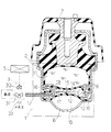
【図1】本発明の第一の実施の形態にかかるものであって円筒型の液体封入式防振装置の全体構成を示す断面図である。
【図2】本発明の第二の実施の形態にかかるものであって縦型式液体封入式防振装置の全体構成を示す縦断面図である。
【図3】本発明の第二の実施の形態に関するものの、その作動態様を示す縦断面図である。
【図4】本発明の第二の実施の形態にかかるものの、その平衡室の構造を変えた変形例の全体構成を示す縦断面図である。
【図5】本発明の第三の実施形態に関するものの、その全体構成を示す縦断面図である。
【符号の説明】
1 防振機構部
11 主室
111 液室
12 副室
13 平衡室
14 仕切板
145 凹凸部
15 ダイヤフラム
16 オリフィス
17 ダイヤフラム(別のダイヤフラム)
18 空気室
19 連通路
2 インシュレータ
3 切換手段
31 切換バルブ
32 ソレノイド
33 絞り弁
5 制御手段
6 ホルダ
66 外筒
7 連結金具
77 内筒
8 ストッパ
88 プロテクタ
9 ブラケット[0001]
TECHNICAL FIELD OF THE INVENTION
BACKGROUND OF THE INVENTION 1. Field of the Invention The present invention relates to a liquid-sealed type vibration damping device capable of obtaining a vibration damping effect based on a flow of a fluid (liquid) sealed therein, and in particular, to a vibration damping device exhibited with the flow of a liquid. BACKGROUND OF THE INVENTION 1. Field of the Invention The present invention relates to a liquid-filled type vibration damping device in which vibration characteristics can be switched to a plurality of stages with a simple structure and low dynamic spring characteristics can be obtained even in a high frequency range.
[0002]
[Prior art]
Among the vibration isolators, especially in the case of engine mounts for automobiles, the engine, which is the power source, is used under various conditions from the idling operation state to the maximum rotation speed. Therefore, it must be able to handle a wide range of frequencies. For this reason, a so-called liquid-filled engine mount (vibration isolator) in which two liquid chambers are provided inside and are connected by orifices has already been devised. It is publicly known in a gazette or the like.
[0003]
[Problems to be solved by the invention]
By the way, the above-mentioned known one has two orifices in order to cope with two kinds of input vibrations in a low frequency range, and by operating these orifices, two kinds of vibrations, for example, an engine It is designed to be able to cope with the idling vibration and the engine shake (vibration cutoff). However, these vibrations have frequencies of around 10 to 30 Hz. By the way, automobile engines are used in various situations, and the frequency range of vibration and noise propagated into a vehicle interior via the engine and an engine mount supporting the engine is also wide. I have. In particular, recently, in addition to the idling vibration and the engine shake, vibration / noise related to engine noise such as muffled sound, which is a vibration in a higher frequency range than these, has become a problem. In order to cut off vibrations in these relatively high frequency ranges, it is desirable to provide a liquid-filled type vibration damping device capable of forming a low dynamic spring constant even in these high frequency ranges. It is an object (problem) of the present invention.
[0004]
[Means for Solving the Problems]
In order to solve the above problems, the present invention has taken the following measures. In other words, according to the first aspect of the present invention, there is provided a connecting member mounted on the vibrating body, a holder mounted on the vehicle body, and an insulator between the connecting metal member and the holder for absorbing and blocking vibration from the vibrating body. , A liquid chamber provided continuously with the insulator and filled with a liquid that is an incompressible fluidComprisingIn a liquid-sealed vibration isolator comprising: a main chamber in which the chamber wall is formed by a part of an insulator, and a liquid is sealed, A sub-chamber connected to the main chamber via an orifice so that the liquid flows, and a sub-chamber provided in a part of the main chamber via a diaphragm, wherein the volume of the chamber is formed to be variable. And an air chamber which is provided around the sub-chamber through another diaphragm and in which air is always introduced, and the equilibrium chamber having such a configuration. , Either negative pressure or atmospheric pressure, continuously or synchronized with engine vibrationhandSwitching means for performing a switching operation so as to be alternately introduced is provided, and further, control means for controlling the switching operation of the switching means is provided.
[0005]
By adopting the above configuration, the present invention has the following effects. That is, in the present invention, an equilibrium chamber is provided inside the main chamber via a diaphragm, and a negative pressure or an atmospheric pressure is appropriately introduced into the equilibrium chamber. is there. The introduction of the negative pressure or the atmospheric pressure is performed through switching means controlled by the control means. That is, by the operation of the switching means, a negative pressure is periodically introduced into the equilibrium chamber at a specific frequency, or a constant negative pressure is continuously introduced. In some cases, the equilibrium chamber is kept open to the atmosphere. Therefore, for example, with respect to idling vibration of the engine forming the vibrating body, the pressure (volume) of the equilibrium chamber is changed by the ON / OFF operation of the switching means, whereby the pressure is input through the insulator. Fluid pressure fluctuations in the main chamber caused by idling vibrations are absorbed. As a result, the dynamic spring constant of the spring system formed by the insulator and the main vibration isolator is reduced. These are intended to absorb and block idling vibration.
[0006]
On the other hand, with respect to high frequency vibration of about 100 Hz to 600 Hz which causes a muffled sound which is a problem during running of the vehicle, the switching means is operated to open the equilibrium chamber to the atmosphere. Thus, the chamber volume of the equilibrium chamber changes freely with respect to the high-frequency vibration input through the insulator and the liquid in the liquid chamber. As a result, the insulator and the liquid in the liquid chamber can freely vibrate, and the dynamic spring constant of the spring system formed by the vibration isolating mechanism can be kept low. Therefore, the effect of blocking vibration in a high frequency range is enhanced. As described above, according to the present invention, by providing the switching means including the switching valve and the like, one orifice, and furthermore, one equilibrium chamber, a plurality of kinds of vibrations can be absorbed and cut off. .
[0007]
Further, with respect to an engine shake which is a vibration of a lower frequency than the idling vibration, the liquid is caused to flow in an orifice connecting between the main chamber and the sub-chamber. Shake absorption and blocking are performed. That is, since the vibration related to the engine shake has a frequency of about 10 Hz, it is difficult to cut off the vibration by reducing the dynamic spring constant. Therefore, in the present invention, a constant negative pressure is introduced into the equilibrium chamber forming the vibration isolation mechanism, and the volume of the equilibrium chamber is set to zero. Thus, the liquid flows in the orifice formed between the main chamber and the sub-chamber, and a predetermined damping force is generated by viscous resistance accompanying the flow of the liquid. . The damping force is used to reduce the engine shake.
[0008]
Next, the second aspect of the invention will be described. This is also basically the same as the first aspect. The feature is that the vibration isolating mechanism has a cylindrical shape. That is, an inner cylinder that forms a connecting fitting attached to the vibrating body and has a cylindrical shape, an outer cylinder that forms a holder that is attached to the vehicle body side and has a cylindrical shape, An insulator provided between the inner cylinder and the outer cylinder and around the inner cylinder; and a liquid chamber provided around the insulator and filled with a liquid that is an incompressible fluid.ComprisingWith respect to a cylindrical liquid-filled vibration damping device comprising: a main chamber in which a chamber wall is formed by a part of an insulator and a liquid is sealed. A sub-chamber, which is connected to the main chamber via an orifice so that the liquid flows, and has a sub-chamber separated from the main chamber by a rigid partition plate; Part is provided through a diaphragm, the equilibrium chamber is formed so that the volume of the chamber is changed, and outside the sub-chamber, provided through another diaphragm, always air And an air chamber to be introduced, and in the equilibrium chamber having such a configuration, either one of negative pressure or atmospheric pressure is continuously or synchronized with engine vibration.handSwitching means for performing a switching operation so as to be alternately introduced is provided, and further, control means for controlling the switching operation of the switching means is provided. By adopting such a configuration, according to the present invention, it is possible to further reduce the size and weight in addition to the above-described claim 1. In addition, space saving can be achieved when supporting the vibrating body.
[0009]
Next, a third aspect of the present invention will be described. In this apparatus, an anti-vibration mechanism including a liquid chamber or the like is provided in series with an insulator. That is, in the liquid-filled type vibration damping device, the vibration damping mechanism section is composed of a liquid chamber provided in series with the insulator, and a main chamber in which a chamber wall is formed by a part of the insulator. A sub-chamber having a configuration in which the main chamber is connected to the main chamber via an orifice so that the liquid flows, and the main chamber is separated from the main chamber by a rigid partition plate; And an equilibrium chamber formed so that either one of the atmospheric pressure and the negative pressure is introduced between the equilibrium chamber and the sub-chamber. In this configuration, an air chamber, which is provided through another diaphragm in the portion and in which air is constantly introduced, is adopted. By adopting such a configuration, according to the present invention, in addition to the above-described claim 1, the vibration from the vibrating body is directly transmitted to the insulator and the liquid in the main chamber. Thus, the effect of blocking vibration is further enhanced. Further, a vibration isolator having a balancing chamber in the main chamber is formed on the basis of the conventional vertical liquid-filled type vibration isolator, thereby improving the assemblability (assembling property) of the entire vibration isolator. Will be achieved.
[0010]
Next, the invention according to claim 4 will be described. This is also basically the same as the third aspect. The feature is that the diaphragm, which also forms the equilibrium chamber, does not adhere to the partition plate, which forms the equilibrium chamber. That is, in a liquid-filled type vibration damping device including a liquid chamber and the like provided in series with the insulator, a partition plate that forms a part of the equilibrium chamber in the above-described vibration damping mechanism, and the equilibrium chamber is also formed. A configuration having an innumerable uneven portion formed so that air can flow between the surface of the partition plate-side contact surface and the surface of the diaphragm-side contact surface where the diaphragm comes into contact. I decided.
[0011]
By adopting such a configuration, the device according to the present invention exhibits the following operation in addition to the above-described third embodiment. That is, a negative pressure or an atmospheric pressure is introduced into the equilibrium chamber, and when the diaphragm forming a part of the equilibrium chamber vibrates (deforms), the diaphragm is moved toward the partition plate by the negative pressure. When it is sucked and comes into contact with the partition plate, it does not come into close contact with the partition plate. Specifically, on the side of the surface of the partition plate which is in contact with the diaphragm, countless fine irregularities are provided when viewed microscopically. The valleys (grooves) formed between these fine irregularities have an overall continuous form. Therefore, even if the diaphragm is sucked by the negative pressure and comes into contact with the surface of the partition plate having the fine concavo-convex portion having such a configuration, many gaps are formed between the two. The groove formed by these gaps communicates with a space other than where the diaphragm exists. Therefore, the diaphragm does not adhere to or adhere to the surface of the partition plate. As a result, the diaphragm operates (deforms) smoothly in response to the introduction of the negative pressure or the atmospheric pressure from the switching means, and the volume change of the equilibrium chamber formed by the diaphragm is smoothly advanced. Become.
[0012]
Next, the invention according to
According to a sixth aspect of the present invention, there is provided a connecting member attached to the vibrator, a holder attached to the vehicle body, an insulator between the connecting member and the holder for absorbing and blocking vibration from the vibrating member, and the insulator. And a vibration isolator provided with a liquid chamber in which a liquid that is an incompressible fluid is enclosed. Is a part of the insulator, the chamber wall of which is formed, is connected to a main chamber in which liquid is sealed, and the main chamber is connected to the main chamber via an orifice so that the liquid flows. A sub-chamber separated from the chamber by a rigid partition plate, and a sub-chamber provided between the main chamber and the partition plate via a diaphragm, wherein one of atmospheric pressure and negative pressure is provided. One And an equilibrium chamber formed such that the volume of the chamber is changed by being introduced.In the equilibrium chamber having such a configuration, one of negative pressure and atmospheric pressure is provided. Switching means for performing a switching operation so as to be introduced continuously or alternately in synchronization with engine vibration, and further provided with control means for controlling the switching operation of the switching means. It is a liquid filled type vibration damping device.
According to a seventh aspect of the present invention, there is provided a coupling member attached to a vibrating body, wherein an inner cylinder having a cylindrical shape and a holder attached to a vehicle body are formed. An outer cylinder, between the inner cylinder and the outer cylinder, an insulator provided around the inner cylinder, and a liquid which is provided around the insulator and is an incompressible fluid. A cylindrical vibration-absorbing mechanism comprising a liquid chamber having a liquid chamber, wherein the chamber wall is formed by a part of an insulator. A main chamber in which the liquid is sealed, and the main chamber is connected to the main chamber via an orifice so that the liquid flows, and the main chamber is separated from the main chamber by a rigid partition plate. And a part of the main room An equilibrium chamber that is provided via a diaphragm and has a chamber volume that is formed so as to change, and the equilibrium chamber having such a configuration includes a negative pressure or an atmospheric pressure. A switching means for performing a switching operation so that either one of them is introduced continuously or alternately in synchronization with engine vibration is provided, and a control means for controlling the switching operation of the switching means is provided. This is a cylindrical liquid-filled type vibration damping device characterized by the following.
[0013]
BEST MODE FOR CARRYING OUT THE INVENTION
An embodiment of the present invention will be described with reference to FIGS. First, a first embodiment of the present invention will be described. Although it relates to the first embodiment, as shown in FIG. 1, the structure is such that an
[0014]
In such a basic configuration, the
[0015]
In such a basic configuration, an
[0016]
Further, a
[0017]
The control means 5 for controlling the switching operation of the switching means 3 comprises a microcomputer (CPU) formed based on a microprocessor unit. The switching means 3 is driven by the control action of the control means 5 having such a configuration, whereby the negative pressure formed by the engine suction negative pressure or the like or the atmospheric pressure formed by opening to the atmosphere is reduced by the equilibrium. It is to be introduced into the
[0018]
Next, an operation mode and the like of the present embodiment having such a configuration will be described. That is, the vibration from the vibrating body side is transmitted to the
[0019]
Next, for an engine shake that is a vibration having a lower frequency than the idling vibration, since the vibration has a low frequency of about 10 Hz, the dynamic spring constant should be reduced. It is difficult to achieve vibration isolation. Therefore, in this embodiment, the vibration related to the engine shake is suppressed (attenuated) by improving the damping characteristics of the vibration isolating mechanism 1. That is, a constant negative pressure is introduced into the
[0020]
On the other hand, with respect to vibration in a high frequency range of about 100 Hz to 600 Hz which causes a muffled sound which is a problem during running of the vehicle, the switching means 3 is operated to bring the
[0021]
Next, a second embodiment of the present invention will be described with reference to FIGS. Although it relates to the present embodiment, as shown in FIG. 2, the structure is such that the connecting
[0022]
In such a basic configuration, the
[0023]
In such a basic configuration, an
[0024]
In this embodiment having such a configuration, the surface structure of the
[0025]
By adopting such a configuration, in the present embodiment, a negative pressure or an atmospheric pressure is introduced into the
[0026]
Next, a third embodiment of the present invention will be described with reference to FIG. In this embodiment, the vibration isolator 1 is formed on the basis of one liquid chamber 111 and one equilibrium chamber (also serving as an air chamber) 13, and the structure is simplified. Is what is being done. That is, although the present embodiment relates to the present embodiment, the structure of the vibration isolating mechanism 1 is provided below the
[0027]
【The invention's effect】
According to the present invention, a connection fitting attached to the vibrator, a holder attached to the vehicle body, an insulator between the connection fitting and the holder for absorbing and blocking vibration from the vibrator, and an insulator A vibration isolating mechanism formed by a liquid chamber or the like in which a liquid that is an incompressible fluid is sealed, and introducing a negative pressure or an atmospheric pressure into the vibration isolating mechanism. As described above, with respect to a liquid-filled type vibration damping device comprising switching means for performing switching operation as described above and control means for controlling switching operation of the switching means, the vibration isolating mechanism portion is formed by a part of the insulator in the chamber. A liquid chamber, in which a wall is formed and in which the vibration from the insulator is directly propagated, is provided in the liquid chamber, and the liquid chamber is provided continuously and via the diaphragm. And an equilibrium chamber into which one of the negative pressure and the atmospheric pressure is introduced. Therefore, by turning on / off the switching means, By changing the volume of the equilibrium chamber, it is possible to absorb the fluctuation of the liquid pressure in the liquid chamber caused by the idling vibration input through the insulator, and as a result, to absorb and block the idling vibration Has become possible.
[0028]
On the other hand, with respect to vibration in a high frequency range of about 100 Hz to 600 Hz which causes a muffled sound which is a problem during traveling of the vehicle, the switching means is operated to open the equilibrium chamber to the atmosphere. This allows the equilibrium chamber to freely change its chamber volume with respect to the high-frequency vibration input through the insulator and the liquid in the liquid chamber, thereby forming the vibration-proof mechanism. The dynamic spring constant of the spring system can be kept low. As a result, it is possible to enhance the effect of blocking vibration in a high frequency range.
[0029]
In addition, for the engine shake, an orifice is provided between the main chamber and the sub-chamber forming the liquid chamber, and the liquid flows between the two chambers. A predetermined damping force is generated by the resistance, and the action of the damping force can suppress the engine shake.
[Brief description of the drawings]
FIG. 1 is a cross-sectional view according to a first embodiment of the present invention, showing an overall configuration of a cylindrical liquid-filled type vibration damping device.
FIG. 2 is a vertical cross-sectional view according to a second embodiment of the present invention, showing an entire configuration of a vertical liquid-filled type vibration damping device.
FIG. 3 is a longitudinal sectional view showing an operation mode of the second embodiment of the present invention.
FIG. 4 is a longitudinal sectional view showing an entire configuration of a modification according to the second embodiment of the present invention, in which the structure of the equilibrium chamber is changed.
FIG. 5 is a longitudinal sectional view showing an entire configuration of a third embodiment of the present invention.
[Explanation of symbols]
1 Anti-vibration mechanism
11 Main room
111 liquid chamber
12 Vice room
13 Equilibrium chamber
14 Divider
145 irregularities
15 Diaphragm
16 orifice
17 diaphragm (another diaphragm)
18 air chamber
19 connecting passage
2 insulator
3 Switching means
31 Switching valve
32 solenoid
33 Throttle valve
5 control means
6 holder
66 outer cylinder
7 Connecting bracket
77 inner cylinder
8 Stopper
88 Protector
9 Bracket
Claims (7)
上記防振機構部を、インシュレータの一部にてその室壁が形成されるものであって液体の封入される主室と、当該主室に、オリフィスを介して上記液体が流動するように連結される副室と、上記主室内の一部にダイヤフラムを介して設けられるものであって、その室内容積が変化するように形成された平衡室と、上記副室の周りに別のダイヤフラムを介して設けられるものであって常時空気の導入される空気室と、からなるようにするとともに、このような構成からなる上記平衡室に、負圧または大気圧のうち、いずれか一方のものを、連続的に、あるいはエンジン振動に同期させて交互に導入させるように切換作動をする切換手段を設け、更に、当該切換手段の切換作動を制御する制御手段を設けるようにしたことを特徴とする液体封入式防振装置。A connection fitting attached to the vibrating body, a holder attached to the vehicle body, an insulator between the connection fitting and the holder for absorbing and blocking vibration from the vibrating body, and provided continuously with the insulator. A vibration-absorbing mechanism comprising a liquid chamber in which a liquid that is an incompressible fluid is enclosed;
The vibration isolation mechanism is connected to a main chamber in which a chamber is formed by a part of an insulator and in which a liquid is sealed, and the liquid flows to the main chamber via an orifice. And a balancing chamber, which is provided through a diaphragm in a part of the main chamber and is formed so that the volume of the chamber changes, and another diaphragm around the sub-chamber. And an air chamber in which air is constantly introduced, and the equilibrium chamber having such a configuration is provided with one of negative pressure and atmospheric pressure, A liquid characterized by providing switching means for performing a switching operation so as to be introduced continuously or alternately in synchronization with engine vibration, and further comprising control means for controlling the switching operation of the switching means. Enclosed Vibration apparatus.
上記防振機構部を、インシュレータの一部にてその室壁が形成されるものであって液体の封入される主室と、当該主室にオリフィスを介して上記液体が流動するように連結されるものであって、上記主室との間が剛体からなる仕切板にて隔てられた構成からなる副室と、上記主室内の一部にダイヤフラムを介して設けられるものであって、その室内容積が変化するように形成された平衡室と、上記副室の外側に、別のダイヤフラムを介して設けられるものであって常時空気の導入される空気室と、からなるようにするとともに、このような構成からなる上記平衡室に、負圧または大気圧のうち、いずれか一方のものを、連続的に、あるいはエンジン振動に同期させて交互に導入させるように切換作動をする切換手段を設け、更に、当該切換手段の切換作動を制御する制御手段を設けるようにしたことを特徴とする円筒型の液体封入式防振装置。An inner cylinder that forms a connection fitting attached to the vibrating body and has a cylindrical shape; an outer cylinder that forms a holder that is mounted on the vehicle body side and has a cylindrical shape; and a between the outer tube, proof consisting comprises an insulator provided around said inner cylinder, the encapsulated by the liquid chamber of the liquid is non-compressible fluid be those provided around of the insulator In a cylindrical liquid-filled vibration isolator comprising a vibration mechanism section,
The vibration isolation mechanism is connected to a main chamber in which a chamber wall is formed by a part of an insulator and in which a liquid is sealed, and the main chamber is connected to the main chamber via an orifice so that the liquid flows. A sub-chamber having a configuration in which the main chamber is separated from the main chamber by a partition plate made of a rigid body, and a sub-chamber provided in a part of the main chamber via a diaphragm, An equilibrium chamber whose volume is changed, and an air chamber which is provided outside of the sub-chamber through another diaphragm and in which air is always introduced, are provided. In the equilibrium chamber having such a configuration, a switching means for performing a switching operation so that either one of the negative pressure or the atmospheric pressure is introduced continuously or alternately in synchronization with engine vibration is provided. , Furthermore, the switch Cylindrical fluid-filled vibration damping device being characterized in that so as to provide a control means for controlling the switching operation of the.
上記防振機構部を、上記インシュレータの一部にて、その室壁が形成されるものであって、上記インシュレータからの振動が直接伝播される液体を、その内部に有する液室と、当該液室に対して直列に、ダイヤフラムを介して設けられるものであって負圧及び大気圧のうち、いずれか一方のものが導入される空気室兼用の平衡室と、からなるようにするとともに、このような構成からなる上記平衡室に、負圧または大気圧のうち、いずれか一方のものを、エンジン振動に同期させて交互に導入させるように切換作動をする切換手段を設け、更に、当該切換手段の切換作動を制御する制御手段を設けるようにしたことを特徴とする液体封入式防振装置。A connection fitting attached to the vibrator, a holder attached to the vehicle body, an insulator interposed between the connection fitting and the holder for absorbing and blocking vibration from the vibrator, and provided in series with the insulator a is a vibration isolating mechanism ing provided with an air chamber which is provided via the diaphragm to the lower portion of the encapsulated are liquid chamber and the liquid chamber of the liquid is non-compressible fluid, consisting essentially of a liquid-filled In the vibration isolator,
A liquid chamber having therein a vibration-absorbing mechanism portion, in which a chamber wall is formed by a part of the insulator, and a liquid to which vibration from the insulator is directly propagated; And an equilibrium chamber, which is provided in series with the chamber via a diaphragm and which also serves as an air chamber into which one of the negative pressure and the atmospheric pressure is introduced. The equilibrium chamber having such a configuration is provided with switching means for performing a switching operation so that either one of the negative pressure or the atmospheric pressure is alternately introduced in synchronization with the engine vibration, and A liquid-filled type vibration damping device characterized by comprising control means for controlling the switching operation of the means.
上記防振機構部は、インシュレータの一部にてその室壁が形成されるものであって液体の封入される主室と、当該主室にオリフィスを介して上記液体が流動するように連結されるとともに、上記主室との間が剛体からなる仕切板にて隔てられた副室と、上記主室と上記仕切板との間にダイヤフラムを介して設けられるものであって、大気圧及び負圧のうちいずれか一方のものが導入されることでその室内容積が変化するように形成された平衡室と、を備えてなり、The vibration isolating mechanism has a chamber wall formed by a part of an insulator, and is connected to a main chamber in which a liquid is sealed, and the main chamber is connected to the main chamber via an orifice so that the liquid flows. A sub-chamber separated from the main chamber by a rigid partition plate, and a diaphragm provided between the main chamber and the partition plate through an atmospheric pressure and a negative pressure. An equilibrium chamber formed such that the chamber volume changes when one of the pressures is introduced,
このような構成からなる上記平衡室に、負圧または大気圧のうち、いずれか一方のものを、連続的に、あるいはエンジン振動に同期させて交互に導入させるように切換作動をする切換手段を設け、更に、当該切換手段の切換作動を制御する制御手段を設けるようにしたことを特徴とする液体封入式防振装置。In the equilibrium chamber having such a configuration, switching means for performing a switching operation such that one of negative pressure and atmospheric pressure is introduced continuously or alternately in synchronization with engine vibration. And a control means for controlling a switching operation of the switching means.
上記防振機構部は、インシュレータの一部にてその室壁が形成されるものであって液体の封入される主室と、当該主室にオリフィスを介して上記液体が流動するように連結されるものであって、上記主室との間が剛体からなる仕切板にて隔てられた構成からなる副室と、上記主室内の一部にダイヤフラムを介して設けられるものであって、その室内容積が変化するように形成された平衡室と、を備えてなり、The vibration isolating mechanism has a chamber wall formed by a part of an insulator, and is connected to a main chamber in which a liquid is sealed, and the main chamber is connected to the main chamber via an orifice so that the liquid flows. A sub-chamber having a configuration in which the main chamber is separated from the main chamber by a partition plate made of a rigid body, and a sub-chamber provided in a part of the main chamber via a diaphragm, An equilibrium chamber formed to have a variable volume,
このような構成からなる上記平衡室に、負圧または大気圧のうち、いずれか一方のものを、連続的に、あるいはエンジン振動に同期させて交互に導入させるように切換作動をする切換手段を設け、更に、当該切換手段の切換作動を制御する制御手段を設けるようにしたことを特徴とする円筒型の液体封入式防振装置。In the equilibrium chamber having such a configuration, switching means for performing a switching operation such that one of negative pressure and atmospheric pressure is introduced continuously or alternately in synchronization with engine vibration. And a control means for controlling the switching operation of the switching means.
Priority Applications (4)
| Application Number | Priority Date | Filing Date | Title |
|---|---|---|---|
| JP28752496A JP3570118B2 (en) | 1996-05-21 | 1996-10-09 | Liquid filled type vibration damping device |
| US09/729,958 US6527260B2 (en) | 1996-05-21 | 2000-12-06 | Liquid-sealing type vibration isolating apparatus |
| US10/126,517 US6712344B2 (en) | 1996-05-21 | 2002-04-22 | Liquid-sealing type variation isolating apparatus |
| US10/747,172 US20040150146A1 (en) | 1996-05-21 | 2003-12-31 | Liquid-sealing type variation isolating apparatus |
Applications Claiming Priority (3)
| Application Number | Priority Date | Filing Date | Title |
|---|---|---|---|
| JP15035296 | 1996-05-21 | ||
| JP8-150352 | 1996-05-21 | ||
| JP28752496A JP3570118B2 (en) | 1996-05-21 | 1996-10-09 | Liquid filled type vibration damping device |
Publications (2)
| Publication Number | Publication Date |
|---|---|
| JPH1038018A JPH1038018A (en) | 1998-02-13 |
| JP3570118B2 true JP3570118B2 (en) | 2004-09-29 |
Family
ID=26479975
Family Applications (1)
| Application Number | Title | Priority Date | Filing Date |
|---|---|---|---|
| JP28752496A Expired - Fee Related JP3570118B2 (en) | 1996-05-21 | 1996-10-09 | Liquid filled type vibration damping device |
Country Status (1)
| Country | Link |
|---|---|
| JP (1) | JP3570118B2 (en) |
Families Citing this family (4)
| Publication number | Priority date | Publication date | Assignee | Title |
|---|---|---|---|---|
| JP3533912B2 (en) * | 1996-12-26 | 2004-06-07 | 東洋ゴム工業株式会社 | Anti-vibration device |
| JP3567936B2 (en) * | 1996-12-26 | 2004-09-22 | 東洋ゴム工業株式会社 | Anti-vibration device |
| JP4937223B2 (en) * | 2008-09-29 | 2012-05-23 | 東海ゴム工業株式会社 | Liquid filled cylindrical vibration isolator |
| JP6063138B2 (en) * | 2012-03-27 | 2017-01-18 | ポリマテック・ジャパン株式会社 | Damper |
-
1996
- 1996-10-09 JP JP28752496A patent/JP3570118B2/en not_active Expired - Fee Related
Also Published As
| Publication number | Publication date |
|---|---|
| JPH1038018A (en) | 1998-02-13 |
Similar Documents
| Publication | Publication Date | Title |
|---|---|---|
| JPS6145130A (en) | Liquid damping type vibration insulating supporting device | |
| JPH04302728A (en) | Liquid sealed vibration isolation device | |
| JP3570118B2 (en) | Liquid filled type vibration damping device | |
| JPH04131537A (en) | High viscous fluid sealing type mount device | |
| JPH03125045A (en) | Liquid damping type vibration isolator | |
| JP2004069005A (en) | Fluid-sealed type vibration damper | |
| JPH0629634B2 (en) | Liquid damping type anti-vibration support device | |
| JP4202866B2 (en) | Vibration isolator | |
| JP3134799B2 (en) | Liquid filled type vibration damping device | |
| JP3570105B2 (en) | Liquid filled type vibration damping device | |
| JP3528030B2 (en) | Liquid filled type vibration damping device | |
| JP3603173B2 (en) | Liquid filled type vibration damping device | |
| JP3570106B2 (en) | Liquid filled type vibration damping device | |
| JP3560038B2 (en) | Liquid filled type vibration damping device | |
| JP3549002B2 (en) | Liquid filled type vibration damping device | |
| JP3502970B2 (en) | Liquid filled type vibration damping device | |
| JP3564592B2 (en) | Anti-vibration device | |
| JP3775195B2 (en) | Liquid filled vibration isolator | |
| JP3458320B2 (en) | Liquid filled type vibration damping device | |
| JP3511124B2 (en) | Liquid filled type vibration damping device | |
| JPH06193670A (en) | Fluid sealed type vibration isolator | |
| JP3498234B2 (en) | Liquid filled type vibration damping device | |
| JP3803835B2 (en) | Cylindrical vibration isolator | |
| JP3692919B2 (en) | Liquid filled vibration isolator | |
| JP3564594B2 (en) | Anti-vibration device |
Legal Events
| Date | Code | Title | Description |
|---|---|---|---|
| TRDD | Decision of grant or rejection written | ||
| A01 | Written decision to grant a patent or to grant a registration (utility model) |
Free format text: JAPANESE INTERMEDIATE CODE: A01 Effective date: 20040608 |
|
| A61 | First payment of annual fees (during grant procedure) |
Free format text: JAPANESE INTERMEDIATE CODE: A61 Effective date: 20040614 |
|
| R150 | Certificate of patent or registration of utility model |
Free format text: JAPANESE INTERMEDIATE CODE: R150 |
|
| FPAY | Renewal fee payment (event date is renewal date of database) |
Free format text: PAYMENT UNTIL: 20080702 Year of fee payment: 4 |
|
| FPAY | Renewal fee payment (event date is renewal date of database) |
Free format text: PAYMENT UNTIL: 20080702 Year of fee payment: 4 |
|
| FPAY | Renewal fee payment (event date is renewal date of database) |
Free format text: PAYMENT UNTIL: 20090702 Year of fee payment: 5 |
|
| FPAY | Renewal fee payment (event date is renewal date of database) |
Free format text: PAYMENT UNTIL: 20090702 Year of fee payment: 5 |
|
| FPAY | Renewal fee payment (event date is renewal date of database) |
Free format text: PAYMENT UNTIL: 20100702 Year of fee payment: 6 |
|
| FPAY | Renewal fee payment (event date is renewal date of database) |
Free format text: PAYMENT UNTIL: 20110702 Year of fee payment: 7 |
|
| FPAY | Renewal fee payment (event date is renewal date of database) |
Free format text: PAYMENT UNTIL: 20120702 Year of fee payment: 8 |
|
| FPAY | Renewal fee payment (event date is renewal date of database) |
Free format text: PAYMENT UNTIL: 20130702 Year of fee payment: 9 |
|
| R250 | Receipt of annual fees |
Free format text: JAPANESE INTERMEDIATE CODE: R250 |
|
| LAPS | Cancellation because of no payment of annual fees |