JP3569578B2 - Thermocompression tools - Google Patents
Thermocompression tools Download PDFInfo
- Publication number
- JP3569578B2 JP3569578B2 JP25575695A JP25575695A JP3569578B2 JP 3569578 B2 JP3569578 B2 JP 3569578B2 JP 25575695 A JP25575695 A JP 25575695A JP 25575695 A JP25575695 A JP 25575695A JP 3569578 B2 JP3569578 B2 JP 3569578B2
- Authority
- JP
- Japan
- Prior art keywords
- pressing
- power supply
- length
- temperature
- thermocompression bonding
- Prior art date
- Legal status (The legal status is an assumption and is not a legal conclusion. Google has not performed a legal analysis and makes no representation as to the accuracy of the status listed.)
- Expired - Fee Related
Links
Images

Classifications
-
- B—PERFORMING OPERATIONS; TRANSPORTING
- B23—MACHINE TOOLS; METAL-WORKING NOT OTHERWISE PROVIDED FOR
- B23K—SOLDERING OR UNSOLDERING; WELDING; CLADDING OR PLATING BY SOLDERING OR WELDING; CUTTING BY APPLYING HEAT LOCALLY, e.g. FLAME CUTTING; WORKING BY LASER BEAM
- B23K2101/00—Articles made by soldering, welding or cutting
- B23K2101/36—Electric or electronic devices
- B23K2101/38—Conductors
Landscapes
- Wire Bonding (AREA)
- Electric Connection Of Electric Components To Printed Circuits (AREA)
Description
【0001】
【発明の属する技術分野】
本発明は、あらかじめめっき等によって半田をプリコートしたプリント配線板等の多数の接続部に、集積回路等の多数のリード線を瞬間加熱により一度に半田付けするための熱圧着用ツールに関するものである。
【0002】
【従来の技術】
集積回路等の多数のリード線を一度に半田付けするための熱圧着用ツールが公知である。この熱圧着用ツールは、一般に高抵抗体であると共に耐半田濡れ性が良好なモリブデン材が使用され、これにパルス電流を流し、ここに発生するジュール熱により加熱される長い押圧面を持ち、この押圧面を多数の半田付け部分に均等に押圧して熱伝導により半田を瞬時に溶融すると共にツールの加圧力によりリード線を同時に半田付けするものであり、瞬時に加熱し得ると共に押圧面ができるだけ広い範囲にわたって均一な温度に保たれていることが望ましい。
【0003】
しかし押圧面を形成する辺(押圧辺)の両端が給電端子に接続されているため、押圧面の熱がこれら給電端子に逃げ、押圧面の中央付近が高温になると共に両端付近で低温になり温度の不均一性が強くなる。このため一定の許容温度範囲内に入る長さ(均熱長)が短くなり一度に半田付けする各部の半田付け状態が不均一になるという問題が生じる。
【0004】
そこで均熱長を長くするため従来は図4のようなツールが提案されている。(実開昭57ー53638号参照)。
図4のものは、押圧面1を形成する辺(押圧辺)2の両端を一対の連結辺3(3a、3b)によって一対の給電端子4(4a、4b)に接続したもので、モリブデン製の板材を略矩形の枠状に形成したものである。ここに押圧辺2の上面すなわち押圧面1の反対側の面を中央付近を上方に隆起させ、この隆起部5により中央付近の放熱性を高めて均熱長を長くしようとするものである。
【0005】
即ちこれらは、押圧辺2の両端が給電端子4への伝熱によって冷えるのに対応して、中央付近を放熱により冷やし、全体としての温度分布の均一化を図るものである。
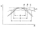
図5において横軸xは押圧辺の長さ方向の位置を、また縦軸は温度tを示している。Δtは許容温度範囲を示し、曲線Aは隆起部5を持たない場合を、曲線Bは図3のように隆起部5を持つ場合の特性を示す。このように図4のツールによれば、従来の特性Aは均熱長aが狭いのに対し、隆起部5を設けることにより均熱長bのように拡大することができるのである。
【0006】
【発明が解決しようとする課題】
しかしながらこれら従来のものでは、均熱長を拡大するためには隆起部5を大型化して放熱量を増やすと共に、電流も増やして発熱量を増大する必要が生じる。このため全体の熱容量が増大し、加熱・冷却の応答性が悪くなると言う問題が生じる。また押圧辺2の両端付近における給電端子4への伝熱量は減らないから、これら両端付近での温度低下が大きくなり、均熱長の拡大にも限度があった。さらに隆起部5を設けるものでは、押圧辺2の温度変化により湾曲する力が発生し、押圧面1が湾曲して多数の半田付け部を均等な圧力で半田付けすることができなくなったり、給電端子4や連結辺3に熱的あるいは機械的なストレスが繰り返し加わり、従来のモリブデン材が有する剛性および耐摩耗性では疲労による強度低下が生じ、破損するという問題があった。
【0007】
本発明はこのような事情に鑑みなされたものであり、加熱・冷却の応答性がよく、均熱長を大幅に拡大でき、温度変化による押圧面の湾曲が発生せず、かつ各部の疲労による強度低下が発生しにくい熱圧着用ツールを提供することを目的とする。
【0008】
【課題を解決するための手段】
本発明によればこのような問題点は、板材を略矩形の枠状に形成し、この枠の一辺を中央で切り欠いて一対の給電端子とする一方、これら給電端子に対向する辺を被ボンデイング材を押圧する押圧辺とした熱圧着ツールにおいて、前記熱圧着用ツールをタングステン鋼で形成し、前記押圧辺の両端と前記各給電端子とをつなぐ2つの辺のそれぞれの長さを押圧辺の長さと略等しくすると共にこれら各辺の断面積を略等しく形成して、前記給電端子を除く各部を非半田被着材で被覆したことを特徴とする熱圧着ツールにより達成される。
【0009】
【発明の実施の形態】
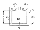
図1は本発明の一実施例を示す正面図、図2はその底面図である。10はタングステン鋼好ましくはタングステンカーバイト鋼製の板材をワイヤカット加工などにより略矩形の枠状に加工して成形された熱圧着用ツールである。この枠状の一辺(上辺)は中央が切り欠かれ、これを挟んで一対の給電端子12(12a、12b)が形成される。これら給電端子12に対向する下辺は断面が一定断面積の矩形である押圧辺14となり、この押圧辺14の下面が被ボンデイング材、例えば集積回路の多数のリード線を押圧する押圧面16となっている。
【0010】
この押圧辺14の両端と給電端子12とをつなぐ一対の辺(連結辺)18(18a、18b)は押圧面16の長さと同等の長さとされ、この連結辺18の断面は押圧辺14とほぼ同一形状かつ同一面積となっている。タングステン鋼はモリブデンに比して剛性および耐摩耗性に優れるので、連結辺18を長くすることができる。しかしながら、タングステン鋼はその組成の中にコバルトが含有されているため半田が被着しやすく、半田が被着した熱圧着用ツールを使用するとリード線間の半田ブリッジによるショートの原因となるので好ましくない。
そこで、給電部12を除いて連結辺18、押圧辺14を金属、非金属等からなる非半田被着材好ましくは被着処理の容易な窒化チタンで被覆している。窒化チタンは蒸着により被着される。
なお20は押圧辺14の中央付近の温度を検出するための熱電対である。
【0011】
このように構成された熱圧着用ツール10の給電端子12a、12bにパルス通電加熱方式によって電流が供給されると、押圧辺16と連結辺18とが発熱する。熱電対20が一定温度を検出すると電流の通流率が変化して平均電流が減少し、一定温度に保たれる。このように一定温度に保たれる間に押圧面16が被ボンデイング材(図示せず)に押圧されてボンデイングが行われ、その後電流が断たれる。するとツール10は熱容量が小さいので速やかにその温度が低下し、ツール10を上昇させて被ボンデイング材から離せばボンデイング操作は終了する。
【0012】
ここに連結辺18は押圧辺14の左右端の上方に延在されているから、この連結辺18で発熱した熱は連結辺18の上部では給電端子12に伝熱するが、連結辺18の下部では押圧辺14の左右端付近を加熱することになる。このため押圧辺16の左右端付近の温度の低下が減少し、この付近から給電端子12に熱が逃げることによる温度降下を補う。この結果押圧辺14の両端付近の温度が上がり、結局図5に示す特性Cのような温度分布となり、均熱長cが長くなる。また押圧辺14には図4の従来のもののような隆起部5がないので熱容量が小さくなり、速やかな温度上昇・降下が可能となる。
【0013】
さらに押圧辺14は等断面積なので、その温度変化による湾曲が発生せず、押圧面16の平面性が良くなり、多数のボンデイング部を均一に押圧して均一な半田付けが可能になる。このためツール10に加わる熱的・機械的なストレスが減り、ツール10の疲労による破損が発生しにくくなる。
【0014】
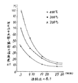
図3に本発明になる熱圧着用ツール10の有用性を示す実験結果を示した。同図において、横軸は熱圧着用ツール10の連結辺18の長さH(図1)を、縦軸は通電終了時における押圧辺14の中央部と端部の温度差Δtを示している。図中の曲線は、押圧辺の長さを36mmの一定とし連結片18の長さHを3、9、17および27mmとした4種類の熱圧着用ツールについて、それぞれ400、300および200℃(押圧辺14の中央部の温度)に加熱した場合の前記温度差Δtをプロットしたものである。
図3から明らかなように、連結辺18の長さHが3mmのものでは温度差が40〜100℃あるのに対し、連結辺18の長さHが27mmのものでは10〜15℃となり、連結辺18が長いほど押圧辺14の中央部と端部の温度差が縮まることが判る。
【0015】
従って、連結辺18を押圧辺14よりも長くすれば、押圧辺14の全長に亙って実用上問題なく均熱化することができる。しかしながら、熱圧着ツール10は前述のごとく熱的、機械的ストレスを繰り返し受けるものであるから連結辺18は剛性の点で短い方がよく、このため本発明における熱圧着ツール10では実用上差し支えのない温度差が得られる長さ、即ち、連結辺18の長さを押圧辺14の長さと略等しくなるように選定した。
【0016】
【発明の効果】
本発明は以上のように、ツールの材質をタングステン鋼とすることによって給電端子と押圧辺とをつなぐ連結辺の剛性を高めて、連結辺の長さを押圧辺の長さと略等しく形成すると共に、押圧辺と連結辺の断面をほぼ均一にしたものであるから、連結辺下部の発熱により加熱された押圧辺の左右付近の熱が給電端子に逃げることによる温度降下を低減させ、また押圧辺の左右付近の熱放散を連結辺下部による加熱で補うことができ、押圧辺の均熱長を大幅に拡大することができる。
【0017】
また押圧辺には隆起部などが無いのでその熱容量が小さくなり、速やかな加熱、冷却が可能となり、作業速度の上昇が図れる。また押圧辺の断面が一定なので、温度変化による湾曲が発生せず多数のボンデイング部を均一に押圧でき、均一な半田付けが可能になると共に、熱変形を吸収することができ、熱的・機械的なストレスによる疲労によりツールが破損するのを防止できる。
【0018】
更に、剛性を高めるために用いたタングステン鋼からなるツール表面を非半田被着材で被覆したので、ツールに半田が被着することがなく、リード線間の半田ブリッジによるショートが生じることもない。
【図面の簡単な説明】
【図1】図1は本発明の一実施例の正面図である。
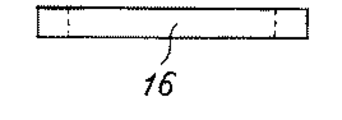
【図2】図2はその底面図である。
【図3】図3は連結辺の長さを変えて測定した押圧辺の中心部と端部との温度差を示す図である。
【図4】図4は従来の熱圧着用ツールの斜視図である。
【図5】図5は押圧面の温度分布図である。
【符号の説明】
10 … 熱圧着用ツール
12 … 給電端子
14 … 押圧辺
16 … 押圧面
18 … 連結辺[0001]
TECHNICAL FIELD OF THE INVENTION
The present invention relates to a thermocompression bonding tool for soldering a large number of lead wires of an integrated circuit or the like at once by instantaneous heating to a large number of connection portions of a printed wiring board or the like which has been precoated with solder by plating or the like. .
[0002]
[Prior art]
Thermocompression bonding tools for soldering a large number of lead wires of an integrated circuit or the like at a time are known. This thermocompression bonding tool is generally made of a molybdenum material that has a high resistance and good solder wettability, passes a pulse current through it, and has a long pressing surface that is heated by Joule heat generated here. This pressing surface is evenly pressed to many soldering parts to melt the solder instantly by heat conduction and to solder the lead wires simultaneously by the pressing force of the tool. It is desirable to keep the temperature as uniform as possible over as wide a range as possible.
[0003]
However, since both ends of the side (pressing side) forming the pressing surface are connected to the power supply terminals, the heat of the pressing surface escapes to these power supply terminals, and the temperature near the center of the pressing surface becomes high and the temperature near the both ends becomes low. The temperature non-uniformity increases. For this reason, the length (soaking length) that falls within a certain allowable temperature range is shortened, and there is a problem that the soldering state of each part to be soldered at one time becomes uneven.
[0004]
Therefore, conventionally, a tool as shown in FIG. 4 has been proposed in order to increase the soaking length. (See Japanese Utility Model Application Laid-Open No. 57-53638).
In FIG. 4, the both ends of a side (pressing side) 2 forming the
[0005]
That is, in response to the fact that both ends of the
In FIG. 5, the horizontal axis x indicates the position in the length direction of the pressed side, and the vertical axis indicates the temperature t. Δt indicates an allowable temperature range, a curve A indicates a characteristic having no
[0006]
[Problems to be solved by the invention]
However, in these conventional devices, in order to increase the soaking length, it is necessary to increase the heat radiation by increasing the size of the raised
[0007]
The present invention has been made in view of such circumstances, has good responsiveness of heating and cooling, can greatly expand the soaking length, does not cause bending of the pressing surface due to temperature change, and is caused by fatigue of each part An object of the present invention is to provide a thermocompression bonding tool in which a decrease in strength is unlikely to occur.
[0008]
[Means for Solving the Problems]
According to the present invention, such a problem is that the plate member is formed in a substantially rectangular frame shape, and one side of this frame is cut off at the center to form a pair of power supply terminals, while the sides facing these power supply terminals are covered. In a thermocompression bonding tool having a pressing side for pressing a bonding material, the thermocompression bonding tool is formed of tungsten steel, and the length of each of two sides connecting both ends of the pressing side and each of the power supply terminals is defined as a pressing side. And a cross-sectional area of each side thereof is made substantially equal to each other, and each part except for the power supply terminal is covered with a non-solder-coated material.
[0009]
BEST MODE FOR CARRYING OUT THE INVENTION
FIG. 1 is a front view showing an embodiment of the present invention, and FIG. 2 is a bottom view thereof.
[0010]
A pair of sides (connecting sides) 18 (18a, 18b) connecting both ends of the
Therefore, the connection side 18 and the
[0011]
When an electric current is supplied to the
[0012]
Here, since the connection side 18 extends above the left and right ends of the
[0013]
Further, since the
[0014]
FIG. 3 shows experimental results showing the usefulness of the
As is clear from FIG. 3, when the length H of the connecting side 18 is 3 mm, the temperature difference is 40 to 100 ° C., whereas when the length H of the connecting side 18 is 27 mm, the temperature difference is 10 to 15 ° C. It can be seen that the longer the connection side 18, the smaller the temperature difference between the center and the end of the
[0015]
Therefore, if the connecting side 18 is made longer than the
[0016]
【The invention's effect】
As described above, the present invention increases the rigidity of the connection side that connects the power supply terminal and the pressing side by using tungsten steel as the material of the tool, and forms the length of the connecting side substantially equal to the length of the pressing side. Since the cross section of the pressing side and the connecting side is substantially uniform, the temperature drop due to the heat near the left and right sides of the pressing side heated by the heat generated at the lower part of the connecting side being released to the power supply terminal is reduced. Can be compensated for by the heat from the lower part of the connecting side, and the soaking length of the pressing side can be greatly increased.
[0017]
Further, since there is no raised portion or the like on the pressing side, its heat capacity becomes small, rapid heating and cooling become possible, and the working speed can be increased. In addition, since the cross section of the pressing side is constant, many bonding parts can be pressed evenly without bending due to temperature change, uniform soldering is possible, and thermal deformation can be absorbed. The tool can be prevented from being damaged by fatigue due to temporary stress.
[0018]
Furthermore, since the surface of the tool made of tungsten steel used for increasing the rigidity is covered with a non-solder adherent, no solder is adhered to the tool and no short circuit occurs due to a solder bridge between the lead wires. .
[Brief description of the drawings]
FIG. 1 is a front view of one embodiment of the present invention.
FIG. 2 is a bottom view thereof.
FIG. 3 is a diagram illustrating a temperature difference between a center portion and an end portion of a pressing side measured by changing a length of a connecting side.
FIG. 4 is a perspective view of a conventional thermocompression bonding tool.
FIG. 5 is a temperature distribution diagram of a pressing surface.
[Explanation of symbols]
10: thermocompression tool 12: power supply terminal 14: pressing side 16: pressing surface 18: connecting side
Claims (1)
Priority Applications (1)
| Application Number | Priority Date | Filing Date | Title |
|---|---|---|---|
| JP25575695A JP3569578B2 (en) | 1995-09-08 | 1995-09-08 | Thermocompression tools |
Applications Claiming Priority (1)
| Application Number | Priority Date | Filing Date | Title |
|---|---|---|---|
| JP25575695A JP3569578B2 (en) | 1995-09-08 | 1995-09-08 | Thermocompression tools |
Publications (2)
| Publication Number | Publication Date |
|---|---|
| JPH0970659A JPH0970659A (en) | 1997-03-18 |
| JP3569578B2 true JP3569578B2 (en) | 2004-09-22 |
Family
ID=17283196
Family Applications (1)
| Application Number | Title | Priority Date | Filing Date |
|---|---|---|---|
| JP25575695A Expired - Fee Related JP3569578B2 (en) | 1995-09-08 | 1995-09-08 | Thermocompression tools |
Country Status (1)
| Country | Link |
|---|---|
| JP (1) | JP3569578B2 (en) |
Cited By (2)
| Publication number | Priority date | Publication date | Assignee | Title |
|---|---|---|---|---|
| JP2011171554A (en) * | 2010-02-19 | 2011-09-01 | Nippon Avionics Co Ltd | Heater tool for thermocompression bonding |
| US10165690B2 (en) | 2015-06-19 | 2018-12-25 | Nippon Telegraph And Telephone Corporation | Solder joint structure of flexible printed circuit board |
Families Citing this family (4)
| Publication number | Priority date | Publication date | Assignee | Title |
|---|---|---|---|---|
| JP5036672B2 (en) * | 2008-09-25 | 2012-09-26 | 日本アビオニクス株式会社 | Heater chip for high-temperature pulse heat and manufacturing method |
| JP2010225819A (en) * | 2009-03-24 | 2010-10-07 | Nippon Avionics Co Ltd | Heater chip |
| CN110153522A (en) * | 2019-06-14 | 2019-08-23 | 昆山盟特展精密机电有限公司 | A self-adhesive solder joint for junction box bus bar welding machine |
| JP2025079808A (en) * | 2023-11-10 | 2025-05-22 | 了 久保田 | Heated head and hot bar joining machine |
-
1995
- 1995-09-08 JP JP25575695A patent/JP3569578B2/en not_active Expired - Fee Related
Cited By (2)
| Publication number | Priority date | Publication date | Assignee | Title |
|---|---|---|---|---|
| JP2011171554A (en) * | 2010-02-19 | 2011-09-01 | Nippon Avionics Co Ltd | Heater tool for thermocompression bonding |
| US10165690B2 (en) | 2015-06-19 | 2018-12-25 | Nippon Telegraph And Telephone Corporation | Solder joint structure of flexible printed circuit board |
Also Published As
| Publication number | Publication date |
|---|---|
| JPH0970659A (en) | 1997-03-18 |
Similar Documents
| Publication | Publication Date | Title |
|---|---|---|
| JPH07183436A (en) | Semiconductor module | |
| JP3569578B2 (en) | Thermocompression tools | |
| JP2001274177A (en) | Semiconductor device and manufacturing method thereof | |
| JP2717867B2 (en) | Bonding tool | |
| JPH0617336Y2 (en) | Bonding tools | |
| CN1187103A (en) | Apparatus for heating and cooling electronic device | |
| JP7370075B2 (en) | heater chip unit | |
| JPS6125249Y2 (en) | ||
| JPH03148425A (en) | Heater device for heat sealing | |
| JPH0230144Y2 (en) | ||
| JP3089156B2 (en) | Lead terminal connection device for ceramic heater | |
| KR20030016427A (en) | Soldering method for mounting electric components | |
| JP2616254B2 (en) | Heating tools | |
| JP2011171554A (en) | Heater tool for thermocompression bonding | |
| CN215791844U (en) | Hot-pressing rivet joint | |
| US7559455B2 (en) | Diebond strip | |
| JPS6120761Y2 (en) | ||
| JP3522434B2 (en) | Heater tool structure of pulse heat welding machine | |
| JP3415414B2 (en) | Thermocompression tools | |
| JP3847240B2 (en) | Press heater and manufacturing method thereof | |
| JP2025136722A (en) | Heating bonding method for heater chips, electrodes and conductors | |
| JPH04117481U (en) | cooling fin device | |
| JP2546178B2 (en) | Leadless diode | |
| JPH03104134A (en) | Thermal pressure bonding head | |
| JPH0878477A (en) | Bonding tools |
Legal Events
| Date | Code | Title | Description |
|---|---|---|---|
| A131 | Notification of reasons for refusal |
Free format text: JAPANESE INTERMEDIATE CODE: A131 Effective date: 20040323 |
|
| TRDD | Decision of grant or rejection written | ||
| A01 | Written decision to grant a patent or to grant a registration (utility model) |
Free format text: JAPANESE INTERMEDIATE CODE: A01 Effective date: 20040615 |
|
| A61 | First payment of annual fees (during grant procedure) |
Free format text: JAPANESE INTERMEDIATE CODE: A61 Effective date: 20040621 |
|
| R150 | Certificate of patent or registration of utility model |
Free format text: JAPANESE INTERMEDIATE CODE: R150 |
|
| S531 | Written request for registration of change of domicile |
Free format text: JAPANESE INTERMEDIATE CODE: R313531 |
|
| R350 | Written notification of registration of transfer |
Free format text: JAPANESE INTERMEDIATE CODE: R350 |
|
| FPAY | Renewal fee payment (event date is renewal date of database) |
Free format text: PAYMENT UNTIL: 20080625 Year of fee payment: 4 |
|
| FPAY | Renewal fee payment (event date is renewal date of database) |
Free format text: PAYMENT UNTIL: 20090625 Year of fee payment: 5 |
|
| FPAY | Renewal fee payment (event date is renewal date of database) |
Free format text: PAYMENT UNTIL: 20090625 Year of fee payment: 5 |
|
| FPAY | Renewal fee payment (event date is renewal date of database) |
Free format text: PAYMENT UNTIL: 20100625 Year of fee payment: 6 |
|
| FPAY | Renewal fee payment (event date is renewal date of database) |
Free format text: PAYMENT UNTIL: 20110625 Year of fee payment: 7 |
|
| FPAY | Renewal fee payment (event date is renewal date of database) |
Free format text: PAYMENT UNTIL: 20110625 Year of fee payment: 7 |
|
| FPAY | Renewal fee payment (event date is renewal date of database) |
Free format text: PAYMENT UNTIL: 20120625 Year of fee payment: 8 |
|
| FPAY | Renewal fee payment (event date is renewal date of database) |
Free format text: PAYMENT UNTIL: 20120625 Year of fee payment: 8 |
|
| FPAY | Renewal fee payment (event date is renewal date of database) |
Free format text: PAYMENT UNTIL: 20130625 Year of fee payment: 9 |
|
| LAPS | Cancellation because of no payment of annual fees |