JP3566696B2 - Vibration wave drive - Google Patents
Vibration wave drive Download PDFInfo
- Publication number
- JP3566696B2 JP3566696B2 JP2002004197A JP2002004197A JP3566696B2 JP 3566696 B2 JP3566696 B2 JP 3566696B2 JP 2002004197 A JP2002004197 A JP 2002004197A JP 2002004197 A JP2002004197 A JP 2002004197A JP 3566696 B2 JP3566696 B2 JP 3566696B2
- Authority
- JP
- Japan
- Prior art keywords
- elastic body
- vibration
- elastic
- driving device
- vibration wave
- Prior art date
- Legal status (The legal status is an assumption and is not a legal conclusion. Google has not performed a legal analysis and makes no representation as to the accuracy of the status listed.)
- Expired - Fee Related
Links
- 238000006243 chemical reaction Methods 0.000 claims description 19
- 238000006073 displacement reaction Methods 0.000 claims description 16
- 239000000463 material Substances 0.000 claims description 8
- 238000005452 bending Methods 0.000 description 16
- 238000010586 diagram Methods 0.000 description 7
- 230000004323 axial length Effects 0.000 description 6
- 230000002093 peripheral effect Effects 0.000 description 5
- 238000000034 method Methods 0.000 description 4
- 238000013016 damping Methods 0.000 description 3
- CNQCVBJFEGMYDW-UHFFFAOYSA-N lawrencium atom Chemical compound [Lr] CNQCVBJFEGMYDW-UHFFFAOYSA-N 0.000 description 3
- 239000002184 metal Substances 0.000 description 3
- 238000004904 shortening Methods 0.000 description 3
- 239000000758 substrate Substances 0.000 description 3
- 230000000694 effects Effects 0.000 description 2
- 229910001369 Brass Inorganic materials 0.000 description 1
- 238000005299 abrasion Methods 0.000 description 1
- 239000010951 brass Substances 0.000 description 1
- 239000000919 ceramic Substances 0.000 description 1
- 230000008878 coupling Effects 0.000 description 1
- 238000010168 coupling process Methods 0.000 description 1
- 238000005859 coupling reaction Methods 0.000 description 1
- 230000005611 electricity Effects 0.000 description 1
- 238000005516 engineering process Methods 0.000 description 1
- 239000007769 metal material Substances 0.000 description 1
- 230000000149 penetrating effect Effects 0.000 description 1
- 230000001902 propagating effect Effects 0.000 description 1
- 229910001220 stainless steel Inorganic materials 0.000 description 1
- 239000010935 stainless steel Substances 0.000 description 1
Images


Landscapes
- General Electrical Machinery Utilizing Piezoelectricity, Electrostriction Or Magnetostriction (AREA)
Description
【0001】
【発明の属する技術分野】
本発明は振動波駆動装置に関するものであり、特に棒状振動波駆動装置に用いられる振動体の構造に関するものである。
【従来の技術】
棒状振動波駆動装置は、金属等の弾性体と電気−機械エネルギー変換素子としての圧電素子とからなる振動体を基本的構成として有しており、この圧電素子に位相の異なる交番信号である交流電圧を印加することにより進行波等の駆動振動を形成する。
【0002】
そして、弾性体の駆動部に接触体を加圧手段を介して加圧接触させ、弾性体の駆動部に形成された駆動振動により接触体を摩擦駆動し、振動体と接触体とを相対移動させるようにしている。
【0003】
このような振動波駆動装置において、振動体をステータ、接触体をロータとして用いたものとして振動波モータがある。
振動波モータの振動体としては、リング状または円板状の弾性体の一面にリング状の圧電素子板を接着した構成のものや、ロータの回転を出力軸を介して取り出す方式、あるいはロータの回転を直接取り出す方式などのものが提供されている。
【0004】
そして、振動波モータはカメラレンズ駆動用途等への製品応用がなされており、円環型のものと棒状型のものが存在する。
【0005】
【発明が解決しようとする課題】
図5(a)はカメラレンズ駆動に用いられている棒状振動波モータの棒状振動体の構成図であり、図5(b)は棒状振動体の軸部における振動モード(z軸は軸方向、r軸はラジアル方向)を示す。
【0006】
101は第1の弾性体、102は第2の弾性体、103は圧電素子である。106は第1の弾性体101、圧電素子103および第2の弾性体102を貫通する軸部材である。この軸部材106はロータ108側の一端が製品への取付け部材107に固定され、他端がボルト115に固定されている。軸部材106の該他端にはねじ部が形成されており、ボルト115を締め付けることで、軸部材106に設けられたフランジ部とボルト115との間の第1の弾性体101、圧電素子103、第2の弾性体102を挟持固定する。108は前述したようにロータであり、116は第1の振動体101に固定されてロータと接する摩擦部材である。
【0007】
この圧電素子103に駆動信号を印加すると、棒状振動体には図5(b)に示す曲げ振動(図5では1次の曲げ振動)が励起されてz軸を略中心とする首振り運動を行い、摩擦部材116がz軸周りの円運動を行う。
【0008】
このような棒状振動波駆動装置を構成する振動体は径方向(ラジアル方向)においては小型化できているが、軸方向(スラスト方向)、つまり軸長においては十分に小型化した構成とはなっていなかった。しかし、振動体の軸長を短くしようとする場合以下のような問題があった。
【0009】
単純に振動体を短くすると共振周波数が増加し、振動変位が小さくなり摩擦駆動効率が悪化したり、高周波のため駆動回路素子が高価であるといった問題や、圧電素子内部での損失が増加したりするといった問題があった。
【0010】
そこで、特開平4−91668号公報において、振動体に小径部を設け共振周波数を下げようとするものが提案されたが、共振周波数を下げるため単に振動体を細くすると、圧電素子や摩擦面の径も小さくなり、圧電素子の発生力や摩擦トルクも低下してモータの出力が小さくなってしまう。
【0011】
このような課題を解決し、棒状振動波駆動装置の短軸化を目的とする技術として特開2001−145376号公報に示されたものがある。これを図6に示す。この発明は、第1の弾性体201と第2の弾性体202との間に圧電素子203を挟持固定する点では従来のものと同じであるが、摩擦面を有する第1の弾性体201を内径部と外径部の2領域に分け、両領域間を薄肉の連結部210でつなぐ点で異なっている。
【0012】
この構成によれば、棒状弾性体の軸長を短くしたとしても、第1の振動体には十分な質量があるために共振周波数を低くすることができる。
【0013】
しかし、この技術によると、共振周波数を下げるため、連結部210を薄くして剛性を低下させると圧電素子の発生変位が連結部210の柔らかいバネに吸収されてしまうため、該駆動力を効率よくロータに伝えることができなくなる。逆に連結部210を厚くすると共振周波数を効果的に下げることができないために、振動体の短軸化を思うように図ることができない。よって更なる改良の余地が残されていた。
【0014】
すなわち、特開2001−145376号公報に示された振動体における上記した課題は、柔らかいバネ(図11に示す連結部210)の先に設けられた質量部を摩擦面とするために生ずるものである。
【0015】
そこで、本願に係る発明の目的は、共振周波数を下げるための機能部材と駆動力を取り出す機能部材を分離し、上記した従来の課題を解決した振動体および振動波駆動装置を提供しようとするものである。
【0016】
【課題を解決するための手段】
【0017】
同様に上記課題を解決するために、本願の請求項1に記載の発明は、第1の弾性体と第2の弾性体との間に電気−機械エネルギー変換素子を有する振動体と、前記振動体に接触する接触体とを備え、前記電気−機械エネルギー変換素子に駆動信号を印加することにより前記振動体に励起された進行波によって前記接触体を駆動する振動波駆動装置において、前記第1の弾性体と前記第2の弾性体との間に、前記振動体の軸方向と直交する方向に延び、前記電気−機械エネルギー変換素子の外径よりも外側に前記接触体が摺動する摺動面を設けた第3の弾性部を有し、前記振動体は、変位方向および次数が同一であって、かつ、両側のそれぞれの端部の変位する相対的割合が異なる複数の固有振動モードを有することを特徴とするものである。
【0018】
同様に上記課題を解決するために、本願の請求項2に記載の発明は、第1の弾性体と第2の弾性体との間に電気−機械エネルギー変換素子を有する振動体と、前記振動体に接触する接触体とを備え、前記電気−機械エネルギー変換素子に駆動信号を印加することにより前記振動体に励起された進行波によって前記接触体を駆動する振動波駆動装置において、前記第1の弾性体と前記第2の弾性体との間に、前記振動体の軸方向と直交する方向に延び、前記電気−機械エネルギー変換素子の外径よりも外側に前記接触体が摺動する摺動面を設けた第3の弾性部を有し、前記第3の弾性体を境として軸方向摺動面側の振動体の動剛性が、非摺動面側の動剛性よりも小さいことを特徴とするものである。
【0019】
【発明の実施の形態】
(第1の実施の形態)
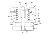
図1は本発明の第1の実施の形態を示したものであり、図1(a)は振動波モータの断面図、図1(b),(c)はこの振動体の曲げ振動モード図である。
【0020】
1は中空円柱状の第1の弾性体で、真鍮等の振動減損失の小さい材料で構成さ
れている。2は円柱状の第2の弾性体であり、第1の弾性体1と同様に振動減衰損失が小さい材料で構成されている。5は振動体の軸方向と直交する方向に延びたフランジ状(円盤状)弾性体であり、第1の弾性体1、第2の弾性体2およびフランジ状弾性体5がねじ部6a,6bを有するシャフト6により一体的に挟持固定されている。このフランジ状弾性体5は耐摩耗性の材料で構成されており、外周近傍の片面でロータ8と接触し、ロータ8を回転駆動させる。図1(a)から明らかなように、ロータ8と接触するフランジ状弾性体5の摺動面は、隣接する第1の弾性体1および圧電素子3の外径よりも外側に位置している。シャフト6は先端部が不図示の装置に連結される質量部7に固定され、振動体を支えるための支持ピンとして作用する。シャフト6のうち第2の弾性体2、圧電素子3およびフランジ状弾性体5の内部に位置していない部分は十分に細く形成されており、振動体が発生する振動を吸収して振動が被駆動装置等へ伝搬するのを防止できるように構成されている。
【0021】
8は前述したようにロータであり、コイルバネ4によって加圧力を受け、フランジ状弾性体5の外周部付近に加圧接触する。このロータ8は弾性体1の外周部に配置可能なため、モータ寸法の短軸化に有利である。9はロータを一体に回転し、被駆動装置に出力を伝達する出力ギアであり、10は出力ギアを支持するための玉軸受けである。
【0022】
なお、第1の形態および後述する第2,3,4の実施の形態においては、便宜上、振動体の軸方向においてフランジ状弾性体を挟んでロータ、第1の弾性体を備えた側を上側、第2の弾性体を備えた側を下側として説明を行う。
【0023】
本実施の形態において、フランジ状弾性体5を境にして上側に位置する第1の弾性体1の直径を小径とし、下側に位置する圧電素子3および第2の圧電素子2の直径を大径としている。これによりフランジ状弾性体5を境として、第1の弾性体1が備わった振動体の上側における振動に対する剛性よりも、第2の弾性体2が備わった振動体の下側における振動に対する剛性のほうが大きくなり、フランジ状弾性体5を境とした両側での動剛性が大きく異なるよう構成されている。このようにフランジ状弾性体5を中心として軸方向両側の外径を異なる非対称形状とすると、図1(b),(c)に示す振動モード図(軸部の径方向変位分布)のように、例えば紙面と平行な面において、2種類の1次の曲げ振動モードを得ることができる。具体的には図1(b)に示す振動モードではフランジ状弾性体5を挟んで振動体の下側が大きく変形するのに対し、図1(c)に示す振動モードではフランジ状弾性体5を挟んで振動体の上側が大きく変形する。つまり同じ変位方向の曲げ振動であっても、振動体の両端の変位する相対的割合が全く異なる2つの振動モードを励起することができる。
【0024】
また、図1(c)に示す振動モードの固有振動数は図1(b)に示す振動モードの固有振動数に比べて小さい値であり、図1(b)と図1(c)の振動モードでの固有振動数は大きく異なったものとなる。これは図1(b)の振動モードが主に外径の大きい第2の弾性体2に合わせた振動モードであるのに対し、図1(c)の振動モードが主に外径の小さい第1の弾性体1に合わせた振動モードであるためである。
【0025】
第2の弾性体2の外径を大きくすることで、第2の弾性体2は軸方向長を短くしても十分な質量を確保することができる。つまり、第2の弾性体2の外径を大きくすることで、軸方向長を短くし、かつ固有振動数の低い振動体を構成することが可能となる。
【0026】
図1(b)からわかるように、フランジ状弾性体5を中心として軸方向両側の動剛性を大きく異ならせると、フランジ状弾性体5の近傍の曲げ振動による変位は小さいものとなる。したがってフランジ状弾性体の近傍に圧電素子3を配置すれば、圧電素子3の歪みを小さく抑えることができ、内部損失の小さいエネルギー効率の高い棒状振動体を提供することができる。
【0027】
隣接する部材よりも外径の大きいフランジ状弾性体5を備えていない図5や図6に示す棒状振動体は異なる2つの曲げ振動モードが生じることはない。また、図7に示すようにフランジ状弾性体65を有した構造であっても、フランジ状弾性体65を挟んだ第1の弾性体61から成る上側と、第2の弾性体62および圧電素子63とから成る下側とが同様の形状、あるいは似た形状である場合には、振動体の両端の変位する相対的割合が全く異なる2つの振動モードを励起することはできない。
【0028】
この図7に示す棒状振動体は、ロータ68を弾性体1の外周部に配置可能という点においては図1の棒状振動体と同様の効果を得ることができるが、1つの曲げ振動モードしか生じないか、あるいは差のあまりない2つの曲げ振動モードが生じるだけであるため、フランジ状弾性体65、圧電素子63の近傍の変位が大きく変化してしまう曲げ振動モードとなる。その結果、圧電素子63に過大な歪みが生じてしまい、圧電素子63内での内部損失を抑えることができず、エネルギー効率の悪い振動体となってしまう。
【0029】
それに対し、本実施の形態である図1の振動体であれば、ロータ8を第1の弾性体1の外側に配置して振動型駆動装置を小型化するとともに、内部でのエネルギー損失を小さく抑えた駆動効率の高い振動体を提供することができる。
【0030】
また、突出したフランジ状弾性体5を金属で構成すれば、ここに歪みが集中しても金属材料の減衰特性は圧電素子に比べて優れているため、内部損失の増加は最小限にとどまり効率の良い短い振動体が構成できる。
【0031】
振動体が大きく構成されていれば振動変位を大きくすることが可能であるため、振動体内部での振動エネルギーの損失が多少大きいとしても、駆動に必要なトルクを発生させることは比較的容易である。しかし、振動体を小さく構成する場合は振動変位もそれほど大きくすることはできないため、振動体内部での振動エネルギーの損失を小さく抑えることは、駆動トルクを十分に確保するためには重要な事項である。
【0032】
圧電素子3に図1(c)に示す振動モードの固有振動数に略合致した交番信号と、図1(b)に示す振動モードの固有振動数に略合致した交番信号とを選択して印加することによって、図1(b)と(c)に示す振動モードを選択的に発生させることが可能である。
【0033】
したがって、フランジ状弾性体の上側に位置する第1の弾性体1を内部減衰の小さい金属等で構成しておけば、第1の弾性体1の振動変位が大きい図1(c)に示す振動モードを発生させた場合に、振動減衰のより小さな高効率の振動体を得ることができる。
【0034】
また、図1(c)に示す振動モードの固有振動数は第1の弾性体1の動剛性の影響を強く受けるため、これを十分に細く形成することで駆動周波数を下げることができ、短軸化を図っても駆動周波数の上昇を招くことはない。
【0035】
さらに、フランジ状弾性体の下側に配置される圧電素子3で発生可能な駆動力の範囲で、フランジ状弾性体の外径寸法、つまりはロータとの接触する面の径を大きくすれば、振動体の軸長を短く構成したとしても駆動トルクを高めることができる。
【0036】
また、本実施の形態では、フランジ状弾性体5を挟んだ両側の動剛性に差を有する振動体とするために、第1の弾性体1と第2の弾性体2との外径を異ならせたが、第1の弾性体1と第2の弾性体2との材質を異ならせたものであってもよい。第2の弾性体2を第1の弾性体1よりも剛性の高い材質で構成すれば、図1(b),(c)に示したものと同様の振動モードを得ることができる。
【0037】
(第2の実施の形態)
図2は本発明の第2の実施の形態を示したものであり、図2(a)は振動体の断面図、図2(b),(c)はこの振動体の曲げ振動モード図である。
【0038】
図1の振動体と異なる点を中心に説明を行う。
【0039】
11は第1の弾性体であり、振動体の軸方向と直交する方向に延びたフランジ状(ディスク状)弾性部15が一体に形成されている。12は第2の弾性体であり、圧電素子13、第1の弾性体11の中心部を貫通し、振動体を支持する軸部材を兼用している。第2の弾性体12の上側の先端部は質量部17に固定され、軸部に設けられたねじ部12bを第1の弾性体11と螺合させることで、圧電素子13を挟持固定している。
【0040】
図2に示した振動体は、第1の弾性体11の上側先端部と第2の弾性体12の下側先端部12aの外径を拡大することで、曲げ振動変位の大きな自由端の質量を大きくし、振動体の固有振動数を低下させたものである。固有振動数を低下できるため、同一の固有振動数であれば、より小型化した振動体を提供することが可能である。
【0041】
本実施形態においても、フランジ状(ディスク状)弾性体15の下側に位置する第2の弾性体12の部位の外径を、フランジ状弾性体15の上側に位置する第1の弾性体11の部位の外径よりも大きくすることで、両者の動剛性に差を持たせ、異なる2つの曲げ振動モードを励起できる構成となっている。
【0042】
図示していないがロータは第1の弾性体11の外周側に配置される。本実施の形態においては、フランジ状弾性体15の外周近傍には、耐摩耗性の摺動部材51が接着され、この摺動部材51がロータと摺動する。図1に示す振動体は、フランジ状弾性体15がロータ8と接するため、フランジ状弾性体15の表面にラップ等による面仕上げ加工を施す必要があるが、本実施の形態においては、摺動部材51を設けてあるので、フランジ状弾性体15の表面に面仕上げ加工を施す必要がなくなる。
【0043】
(第3の実施の形態)
図3は本発明の第3の実施の形態を示す振動体の断面図である。
【0044】
本実施の形態においても図1に示した振動体と異なる点を中心に説明を行う。
【0045】
21は第1の弾性体、22は第2の弾性体、23は圧電素子であり、25は振動体の軸方向と直交する方向に延びたフランジ状(ディスク状)弾性体である。第1の弾性体21には第2の弾性体22、圧電素子23、フランジ状弾性体25を貫通する軸部を有し、軸部の先端が第2の弾性体22の下側で質量部27に固定され、振動体全体を支持している。この軸部には、ねじ部21bとフランジ部21cとが形成されており、第2の弾性体22をねじ部21bに螺合させ、第2の弾性体22とフランジ部21cとの間にフランジ状弾性体25と圧電素子23とを挟持固定する。
【0046】
図示していないが、ロータは第1の弾性体21の21aおよび21cの外周側に配置される。
【0047】
本実施の形態においても、フランジ状弾性体25の上側に位置する第1の弾性体21に、フランジ状弾性体25の下側に位置する第2の弾性体22の外径よりも細い部分を設け、フランジ状弾性体25を挟んだ2つの弾性体の動剛性に差を設けている。これにより図示していないが、図1、図2に示した振動体と同様に2つの異なる曲げ振動モードを励起することができる。
【0048】
また、第1の弾性体21は図2の振動体と同様に先端部の外径を拡大し、振動体の固有振動数を低下させている。
【0049】
フランジ状弾性体25は、耐摩耗性を有しかつ内部歪みによる振動減衰損失の小さい材料、例えばセラミックや焼き入れしたステンレス等が用いられ、ロータの摺動面25aおよび挟持面25b,25cをやや突出させ、ラップによる面仕上げ加工時間を少なくて済むようにしている。尚、同時にラップを施せるように摺動面25aと挟持面25cは同一面内に存在している。
【0050】
(第4の実施の形態)
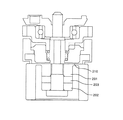
図4は第4の実施の形態を示す振動波モータの断面図である。
【0051】
31は第1の弾性体、32は第2の弾性体、33は圧電素子であり、35は振動体の軸方向と直交する方向に延びたフランジ状弾性体である。
【0052】
36はシャフトで、下部には振動体挟持用のネジ36aが、上部には質量部37と結合する結合用のネジ36cが設けられている。ロータ38の外周には接触用のバネ38aが接着等により結合され、また内周にはバネケース38bが嵌合している。39は出力ギアで、バネケース38bに対してラジアル方向に相対移動せぬよう嵌合結合している。34は加圧用のコイルバネである。質量部37とギア39との結合部40は滑り軸受けを構成している。44は圧電素子33への給電用のフレキシブル基板である。
【0053】
そして、バネケース38bの下端と出力ギア39との間に加圧用のバネ34が配置され、このバネ34のバネ力により、ロータ38の外周部に固定された接触バネ38aのバネ端がディスク状弾性体35の上面に加圧接触している。なお、質量部37はシャフト36から外部へ漏れる振動を遮断する。
【0054】
第1の弾性体31は第2の弾性体32よりも外径が小さく構成されており、本実施の形態においても、図1、図2に示した振動体と同様に2つの異なる曲げ振動モードを励起することができる。
【0055】
フレキシブル基板44には図示していない駆動回路から駆動信号が供給されており、この駆動回路は、2つの異なる曲げ振動モードの一方を励起するための駆動振動を選択してフレキシブル基板44に供給する。
【0056】
なお、本実施の形態は振動体を固定とし、該振動体に加圧接触する接触体としてのロータを可動としているが、本発明はこれに限定されるものではなく、接触体を固定、振動体を可動としても良く、振動体と接触体とを振動体のフランジ状に突出するディスク状弾性体に形成される駆動振動により相対的に摩擦駆動させればよい。
【0057】
【発明の効果】
以上説明したように本発明によれば、軸方向長が短く、かつ、内部での振動エネルギー損失の小さい振動体を構成することができ、小型でエネルギー損失の少ない振動波駆動装置を提供することが可能になる。
【0058】
また、振動体がロータ等の接触体と接する部位の接触径が大きいため、低速・高トルクの振動波駆動装置の出力特長を発揮しやすく、更には、構成部品のなかで比較的高価な圧電素子が小さく済むためコストを抑えることもできる。
【0059】
さらに、突出した弾性体の外周部にロータを配置できるため、振動波駆動装置としての全長も短くなる。
【図面の簡単な説明】
【図1】本発明の第1の実施の形態を示し、(a)は振動波モータの断面図、(b)(c)は振動体の振動モードを示す図
【図2】本発明の第2の実施の形態を示し、(a)は振動波モータの断面図、(b)(c)は振動体の振動モードを示す図
【図3】本発明の第3の実施の形態の振動体の断面図
【図4】本発明の第4の実施の形態の振動波モータの断面図
【図5】(a)は従来の振動波モータの断面図、(b)は振動体の振動モードを示す図
【図6】従来の振動波モータの断面図
【図7】フランジ状弾性体を挟んで略上下対称な形状である振動体を示す図
【符号の説明】
1,11,21,31 第1の弾性体
2,12,22,32 第2の弾性体
3,13,23,33 圧電素子(電気−機械エネルギー変換素子)
4,34 コイルバネ
5,15,25,35 フランジ状弾性体(フランジ状弾性部)
6,36 シャフト
7,17,27,37 質量部
8,38 ロータ
9,39 ギア
10,40 軸受け
44 フレキシブル基板 [0001]
TECHNICAL FIELD OF THE INVENTION
The present invention relates to a vibration wave driving device, and more particularly to a structure of a vibrating body used in a rod-shaped vibration wave driving device.
[Prior art]
The rod-shaped vibration wave driving device basically has a vibrating body composed of an elastic body such as a metal and a piezoelectric element as an electro-mechanical energy conversion element, and the piezoelectric element has an alternating signal that is an alternating signal having a different phase. A driving vibration such as a traveling wave is formed by applying a voltage.
[0002]
Then, the contact body is brought into pressure contact with the driving section of the elastic body via the pressurizing means, and the contact body is frictionally driven by the driving vibration formed on the driving section of the elastic body, so that the vibration body and the contact body are relatively moved. I try to make it.
[0003]
In such a vibration wave driving device, there is a vibration wave motor using a vibration body as a stator and a contact body as a rotor.
As a vibrating body of the vibration wave motor, a structure in which a ring-shaped piezoelectric element plate is adhered to one surface of a ring-shaped or disk-shaped elastic body, a method of taking out the rotation of the rotor via an output shaft, or A method of directly extracting rotation is provided.
[0004]
The vibration wave motor is applied to a product such as a camera lens driving application, and there are a ring type and a rod type.
[0005]
[Problems to be solved by the invention]
FIG. 5A is a configuration diagram of a rod-shaped vibrating body of a rod-shaped vibrating wave motor used for driving a camera lens, and FIG. 5B is a vibration mode in a shaft portion of the rod-shaped vibrating body (z axis is an axial direction; The r axis indicates the radial direction).
[0006]
101 is a first elastic body, 102 is a second elastic body, and 103 is a piezoelectric element.
[0007]
When a drive signal is applied to the
[0008]
The vibrating body constituting such a rod-shaped vibration wave driving device can be miniaturized in the radial direction (radial direction), but is sufficiently miniaturized in the axial direction (thrust direction), that is, in the axial length. I didn't. However, when trying to shorten the axial length of the vibrating body, there are the following problems.
[0009]
Simply shortening the vibrating body increases the resonance frequency, reduces the vibration displacement and reduces the friction drive efficiency, increases the cost of the drive circuit element due to the high frequency, and increases the loss inside the piezoelectric element. There was a problem of doing.
[0010]
In view of this, Japanese Patent Application Laid-Open No. Hei 4-91668 has proposed a method of reducing the resonance frequency by providing a small-diameter portion in the vibrating body. The diameter becomes smaller, the force generated by the piezoelectric element and the friction torque are reduced, and the output of the motor is reduced.
[0011]
Japanese Patent Application Laid-Open No. 2001-145376 discloses a technique for solving such problems and shortening the axis of the rod-shaped vibration wave driving device. This is shown in FIG. This invention is the same as the conventional one in that the
[0012]
According to this configuration, even if the axial length of the rod-shaped elastic body is shortened, the resonance frequency can be lowered because the first vibrator has a sufficient mass.
[0013]
However, according to this technology, when the connecting
[0014]
That is, the above-described problem in the vibrating body disclosed in Japanese Patent Application Laid-Open No. 2001-145376 is caused by using a mass portion provided at the tip of a soft spring (the connecting
[0015]
Therefore, an object of the invention according to the present application is to provide a vibrating body and a vibration wave driving device which solve the above-mentioned conventional problems by separating a functional member for lowering the resonance frequency and a functional member for extracting the driving force. It is.
[0016]
[Means for Solving the Problems]
[0017]
Similarly in order to solve the above problems, the invention according to a first aspect of the present invention, electricity between the first elastic body and second elastic body - a vibrating body having a mechanical energy conversion element, the vibration A contact body that comes into contact with a body, wherein the vibration-wave driving device drives the contact body by a traveling wave excited by the vibration body by applying a drive signal to the electro-mechanical energy conversion element. A sliding member that extends in a direction orthogonal to the axial direction of the vibrating member and slides outside the outer diameter of the electro-mechanical energy conversion element between the elastic member and the second elastic member. A third elastic portion provided with a moving surface, wherein the vibrating body has a plurality of natural vibration modes having the same displacement direction and the same order and different relative proportions of displacement of respective ends on both sides. Which is characterized by having
[0018]
Similarly, in order to solve the above problem, an invention according to claim 2 of the present application is directed to a vibrating body having an electro-mechanical energy conversion element between a first elastic body and a second elastic body; A contact body that comes into contact with a body, wherein the vibration-wave driving device drives the contact body by a traveling wave excited by the vibration body by applying a drive signal to the electro-mechanical energy conversion element. A sliding member that extends in a direction orthogonal to the axial direction of the vibrating member and slides outside the outer diameter of the electro-mechanical energy conversion element between the elastic member and the second elastic member. It has a third elastic portion provided with a moving surface, and the dynamic rigidity of the vibrating body on the axial sliding surface side is smaller than the dynamic rigidity on the non-sliding surface side with respect to the third elastic body. It is a feature.
[0019]
BEST MODE FOR CARRYING OUT THE INVENTION
(First Embodiment)
FIG. 1 shows a first embodiment of the present invention. FIG. 1 (a) is a sectional view of a vibration wave motor, and FIGS. 1 (b) and 1 (c) are bending vibration mode diagrams of the vibrating body. It is.
[0020]
Reference numeral 1 denotes a hollow columnar first elastic body made of a material having a small vibration loss such as brass. Reference numeral 2 denotes a columnar second elastic body, which is made of a material having a small vibration attenuation loss, like the first elastic body 1.
[0021]
Reference numeral 8 denotes a rotor, as described above, which is pressed by the coil spring 4 and comes into pressure contact with the vicinity of the outer peripheral portion of the flange-shaped
[0022]
In the first embodiment and the second, third, and fourth embodiments to be described later, for convenience, the rotor and the side provided with the first elastic body are placed with the flange-like elastic body interposed therebetween in the axial direction of the vibrating body. The description will be made with the side provided with the second elastic body as the lower side.
[0023]
In the present embodiment, the diameter of the first elastic body 1 located on the upper side of the flange-like
[0024]
Further, the natural frequency of the vibration mode shown in FIG. 1C is a smaller value than the natural frequency of the vibration mode shown in FIG. 1B, and the vibration shown in FIG. 1B and FIG. The natural frequencies in the modes are very different. The vibration mode of FIG. 1B is a vibration mode mainly adapted to the second elastic body 2 having a large outer diameter, whereas the vibration mode of FIG. This is because the vibration mode is adapted to the elastic body 1.
[0025]
By increasing the outer diameter of the second elastic body 2, a sufficient mass of the second elastic body 2 can be ensured even if the axial length is shortened. That is, by increasing the outer diameter of the second elastic body 2, it is possible to configure a vibrating body having a short axial length and a low natural frequency.
[0026]
As can be seen from FIG. 1B, when the dynamic rigidity on both sides in the axial direction is largely different from the flange-like
[0027]
Figure 5 and the rod-like vibrator shown in FIG. 6 is not that the two bending vibration modes having different occurs without a flange-like bullet
[0028]
The bar-shaped vibrating body shown in FIG. 7 can obtain the same effect as the bar-shaped vibrating body of FIG. 1 in that the
[0029]
On the other hand, in the case of the vibrating body of FIG. 1 according to the present embodiment, the rotor 8 is disposed outside the first elastic body 1 to reduce the size of the vibration type driving device and reduce the internal energy loss. It is possible to provide a vibrating body with suppressed driving efficiency.
[0030]
Also, if the protruding flange-like
[0031]
If the vibrating body is configured to be large, it is possible to increase the vibration displacement, so even if the loss of vibration energy inside the vibrating body is somewhat large, it is relatively easy to generate the torque required for driving. is there. However, when the vibrating body is configured to be small, the vibration displacement cannot be increased so much.To minimize the loss of vibration energy inside the vibrating body is an important matter for ensuring sufficient driving torque. is there.
[0032]
An alternating signal substantially matching the natural frequency of the vibration mode shown in FIG. 1C and an alternating signal almost matching the natural frequency of the vibration mode shown in FIG. 1B are selectively applied to the
[0033]
Therefore, if the first elastic body 1 located on the upper side of the flange-like elastic body is made of a metal or the like having a small internal damping, the vibration shown in FIG. When a mode is generated, it is possible to obtain a high-efficiency vibrating body with smaller vibration damping.
[0034]
Further, since the natural frequency of the vibration mode shown in FIG. 1C is strongly influenced by the dynamic rigidity of the first elastic body 1, the driving frequency can be reduced by forming the first elastic body 1 sufficiently thin. Axialization does not increase the drive frequency.
[0035]
Furthermore, if the outer diameter of the flange-shaped elastic body, that is, the diameter of the surface in contact with the rotor, is increased within the range of the driving force that can be generated by the
[0036]
In the present embodiment, in order to provide a vibrating body having a difference in dynamic rigidity on both sides of the flange-like
[0037]
(Second embodiment)
2A and 2B show a second embodiment of the present invention. FIG. 2A is a sectional view of a vibrating body, and FIGS. 2B and 2C are bending vibration mode diagrams of the vibrating body. is there.
[0038]
The description will focus on the differences from the vibrator of FIG.
[0039]
Reference numeral 11 denotes a first elastic body, which is integrally formed with a flange-like (disk-like)
[0040]
The vibrating body shown in FIG. 2 is configured such that the outer diameters of the upper end of the first elastic body 11 and the
[0041]
Also in the present embodiment, the outer diameter of the portion of the second
[0042]
Although not shown, the rotor is arranged on the outer peripheral side of the first elastic body 11. In the present embodiment, a wear-resistant sliding
[0043]
(Third embodiment)
FIG. 3 is a cross-sectional view of a vibrating body according to a third embodiment of the present invention.
[0044]
Also in the present embodiment, description will be made focusing on points different from the vibrating body shown in FIG.
[0045]
21 is a first elastic body, 22 is a second elastic body, 23 is a piezoelectric element, and 25 is a flange-like (disk-like) elastic body extending in a direction orthogonal to the axial direction of the vibrating body. The first
[0046]
Although not shown, the rotor is disposed on the outer peripheral side of the first
[0047]
Also in the present embodiment, a portion smaller than the outer diameter of the second
[0048]
Further, the first
[0049]
The flange-like
[0050]
(Fourth embodiment)
FIG. 4 is a sectional view of a vibration wave motor according to a fourth embodiment.
[0051]
31 is a first elastic body, 32 is a second elastic body, 33 is a piezoelectric element, and 35 is a flange-like elastic body extending in a direction perpendicular to the axial direction of the vibrating body.
[0052]
A
[0053]
A pressurizing
[0054]
The first
[0055]
A drive signal is supplied to the
[0056]
In the present embodiment, the vibrating body is fixed, and the rotor as the contact body that presses and contacts the vibrating body is movable. However, the present invention is not limited to this. The body may be movable, and the vibrating body and the contact body may be frictionally driven by driving vibration formed on a disk-shaped elastic body protruding in a flange shape of the vibrating body.
[0057]
【The invention's effect】
As described above, according to the present invention, it is possible to configure a vibrating body having a short axial length and a small internal vibration energy loss, and to provide a small-sized vibration wave driving device with small energy loss. Becomes possible.
[0058]
In addition, since the vibrating body has a large contact diameter at a portion where the vibrating body comes into contact with a contact body such as a rotor, it is easy to exhibit the output characteristics of a low-speed, high-torque vibration wave driving device. Since the element can be small, the cost can be reduced.
[0059]
Further, since the rotor can be arranged on the outer periphery of the protruding elastic body, the overall length of the vibration wave driving device is also reduced.
[Brief description of the drawings]
FIGS. 1A and 1B show a first embodiment of the present invention, in which FIG. 1A is a sectional view of a vibration wave motor, and FIGS. 1B and 1C are diagrams showing vibration modes of a vibrating body. FIGS. FIGS. 3A and 3B show a second embodiment of the present invention, in which FIG. 3A is a cross-sectional view of a vibration wave motor, and FIGS. 3B and 3C are diagrams showing a vibration mode of the vibrating body. FIGS. FIG. 4 is a cross-sectional view of a vibration wave motor according to a fourth embodiment of the present invention. FIG. 5A is a cross-sectional view of a conventional vibration wave motor, and FIG. FIG. 6 is a cross-sectional view of a conventional vibration wave motor. FIG. 7 is a diagram showing a vibrating body that is substantially vertically symmetrical with a flange-like elastic body interposed therebetween.
1, 11, 21, 31 First
4,34
6,36
Claims (12)
前記第1の弾性体と前記第2の弾性体との間に、前記振動体の軸方向と直交する方向に延び、前記電気−機械エネルギー変換素子の外径よりも外側に前記接触体が摺動する摺動面を設けた第3の弾性部を有し、前記振動体は、変位方向および次数が同一であって、かつ、両側のそれぞれの端部の変位する相対的割合が異なる複数の固有振動モードを有することを特徴とする振動波駆動装置。A vibrating body having an electro-mechanical energy conversion element between the first elastic body and the second elastic body; and a contact body contacting the vibrating body, wherein a drive signal is transmitted to the electro-mechanical energy conversion element. In a vibration wave driving device that drives the contact body by a traveling wave excited by the vibration body by applying,
The contact body extends between the first elastic body and the second elastic body in a direction orthogonal to the axial direction of the vibrating body, and slides outside an outer diameter of the electro-mechanical energy conversion element. A third elastic portion provided with a moving sliding surface, wherein the vibrating body has a plurality of displacement units having the same displacement direction and the same order and different relative proportions of displacement of respective ends on both sides. A vibration wave driving device having a natural vibration mode.
前記第1の弾性体と前記第2の弾性体との間に、前記振動体の軸方向と直交する方向に延び、前記電気−機械エネルギー変換素子の外径よりも外側に前記接触体が摺動する摺動面を設けた第3の弾性部を有し、前記第3の弾性部を境として軸方向摺動面側の振動体の動剛性が、非摺動面側の動剛性よりも小さいことを特徴とする振動波駆動装置。A vibrating body having an electro-mechanical energy conversion element between the first elastic body and the second elastic body; and a contact body contacting the vibrating body, wherein a drive signal is transmitted to the electro-mechanical energy conversion element. In a vibration wave driving device that drives the contact body by a traveling wave excited by the vibration body by applying,
The contact body extends between the first elastic body and the second elastic body in a direction orthogonal to the axial direction of the vibrating body, and slides outside an outer diameter of the electro-mechanical energy conversion element. A third elastic portion provided with a moving sliding surface, wherein the dynamic rigidity of the vibrating body on the axial sliding surface side is greater than the dynamic rigidity on the non-sliding surface side with respect to the third elastic portion. A vibration wave driving device characterized by being small.
Priority Applications (9)
| Application Number | Priority Date | Filing Date | Title |
|---|---|---|---|
| JP2002004197A JP3566696B2 (en) | 2001-01-22 | 2002-01-11 | Vibration wave drive |
| US10/044,936 US6930436B2 (en) | 2001-01-22 | 2002-01-15 | Vibration element and vibration wave driving apparatus |
| DE60209266T DE60209266T2 (en) | 2001-01-22 | 2002-01-21 | Vibrating element and vibration shaft drive |
| EP02001426A EP1225681B1 (en) | 2001-01-22 | 2002-01-21 | Vibration element and vibration wave driving apparatus |
| EP05001534A EP1531500B1 (en) | 2001-01-22 | 2002-01-21 | Vibration wave driving apparatus |
| KR10-2002-0003487A KR100523109B1 (en) | 2001-01-22 | 2002-01-22 | Vibration wave driving apparatus |
| CNB021024588A CN1186825C (en) | 2001-01-22 | 2002-01-22 | Vibrating element and vibrating wave driving device |
| US10/952,762 US6989624B2 (en) | 2001-01-22 | 2004-09-30 | Vibration element and vibration wave driving apparatus |
| US11/133,395 US7215063B2 (en) | 2001-01-22 | 2005-05-20 | Vibration element and vibration wave driving apparatus |
Applications Claiming Priority (3)
| Application Number | Priority Date | Filing Date | Title |
|---|---|---|---|
| JP2001-13366 | 2001-01-22 | ||
| JP2001013366 | 2001-01-22 | ||
| JP2002004197A JP3566696B2 (en) | 2001-01-22 | 2002-01-11 | Vibration wave drive |
Publications (3)
| Publication Number | Publication Date |
|---|---|
| JP2002291265A JP2002291265A (en) | 2002-10-04 |
| JP3566696B2 true JP3566696B2 (en) | 2004-09-15 |
| JP2002291265A5 JP2002291265A5 (en) | 2004-12-09 |
Family
ID=26608077
Family Applications (1)
| Application Number | Title | Priority Date | Filing Date |
|---|---|---|---|
| JP2002004197A Expired - Fee Related JP3566696B2 (en) | 2001-01-22 | 2002-01-11 | Vibration wave drive |
Country Status (1)
| Country | Link |
|---|---|
| JP (1) | JP3566696B2 (en) |
Families Citing this family (1)
| Publication number | Priority date | Publication date | Assignee | Title |
|---|---|---|---|---|
| JP6012226B2 (en) | 2012-04-02 | 2016-10-25 | キヤノン株式会社 | Vibration wave driving device and driving circuit thereof |
-
2002
- 2002-01-11 JP JP2002004197A patent/JP3566696B2/en not_active Expired - Fee Related
Also Published As
| Publication number | Publication date |
|---|---|
| JP2002291265A (en) | 2002-10-04 |
Similar Documents
| Publication | Publication Date | Title |
|---|---|---|
| US7215063B2 (en) | Vibration element and vibration wave driving apparatus | |
| JP5709413B2 (en) | Vibration type driving device | |
| JP4027090B2 (en) | Vibration body and vibration wave drive device | |
| JPH11235062A (en) | Vibration actuator driver and lens barrel | |
| JPH1146486A (en) | Vibration actuator and manufacture of vibration-body tightening member in the actuator | |
| KR100485882B1 (en) | Vibration element and vibration wave driving apparatus | |
| JP5932402B2 (en) | Vibration wave drive | |
| JP3566696B2 (en) | Vibration wave drive | |
| JP4026930B2 (en) | Vibration wave device and vibration wave drive device | |
| JP3566711B2 (en) | Vibration wave drive | |
| JP3902955B2 (en) | Vibration body and vibration wave drive device | |
| JP4835042B2 (en) | Vibration wave motor | |
| JPH07178370A (en) | Vibrator and vibrating actuator | |
| JP2001016875A (en) | Oscillatory wave drive device | |
| JP3299670B2 (en) | Vibration wave drive | |
| JP2004112924A (en) | Oscillatory wave drive unit | |
| JP2002291265A5 (en) | ||
| JPH01243861A (en) | Oscillatory wave motor | |
| JPH02266877A (en) | Ultrasonic motor | |
| JPH0678568A (en) | Ultrasonic motor | |
| JP2010193591A (en) | Ultrasonic motor | |
| JPH06276767A (en) | Ultrasonic motor | |
| JP2003047263A (en) | Oscillatory wave drive | |
| JP2000245178A (en) | Vibrating actuator | |
| JP2000245174A (en) | Vibrating actuator |
Legal Events
| Date | Code | Title | Description |
|---|---|---|---|
| A975 | Report on accelerated examination |
Free format text: JAPANESE INTERMEDIATE CODE: A971005 Effective date: 20040205 |
|
| A131 | Notification of reasons for refusal |
Free format text: JAPANESE INTERMEDIATE CODE: A131 Effective date: 20040210 |
|
| A521 | Request for written amendment filed |
Free format text: JAPANESE INTERMEDIATE CODE: A523 Effective date: 20040412 |
|
| TRDD | Decision of grant or rejection written | ||
| A01 | Written decision to grant a patent or to grant a registration (utility model) |
Free format text: JAPANESE INTERMEDIATE CODE: A01 Effective date: 20040608 |
|
| A61 | First payment of annual fees (during grant procedure) |
Free format text: JAPANESE INTERMEDIATE CODE: A61 Effective date: 20040610 |
|
| R150 | Certificate of patent or registration of utility model |
Free format text: JAPANESE INTERMEDIATE CODE: R150 Ref document number: 3566696 Country of ref document: JP Free format text: JAPANESE INTERMEDIATE CODE: R150 |
|
| FPAY | Renewal fee payment (event date is renewal date of database) |
Free format text: PAYMENT UNTIL: 20080618 Year of fee payment: 4 |
|
| FPAY | Renewal fee payment (event date is renewal date of database) |
Free format text: PAYMENT UNTIL: 20090618 Year of fee payment: 5 |
|
| FPAY | Renewal fee payment (event date is renewal date of database) |
Free format text: PAYMENT UNTIL: 20090618 Year of fee payment: 5 |
|
| FPAY | Renewal fee payment (event date is renewal date of database) |
Free format text: PAYMENT UNTIL: 20100618 Year of fee payment: 6 |
|
| FPAY | Renewal fee payment (event date is renewal date of database) |
Free format text: PAYMENT UNTIL: 20110618 Year of fee payment: 7 |
|
| FPAY | Renewal fee payment (event date is renewal date of database) |
Free format text: PAYMENT UNTIL: 20120618 Year of fee payment: 8 |
|
| FPAY | Renewal fee payment (event date is renewal date of database) |
Free format text: PAYMENT UNTIL: 20120618 Year of fee payment: 8 |
|
| FPAY | Renewal fee payment (event date is renewal date of database) |
Free format text: PAYMENT UNTIL: 20130618 Year of fee payment: 9 |
|
| LAPS | Cancellation because of no payment of annual fees |