JP3566334B2 - Image processing apparatus and method - Google Patents
Image processing apparatus and method Download PDFInfo
- Publication number
- JP3566334B2 JP3566334B2 JP05626394A JP5626394A JP3566334B2 JP 3566334 B2 JP3566334 B2 JP 3566334B2 JP 05626394 A JP05626394 A JP 05626394A JP 5626394 A JP5626394 A JP 5626394A JP 3566334 B2 JP3566334 B2 JP 3566334B2
- Authority
- JP
- Japan
- Prior art keywords
- image processing
- types
- similarity
- determination
- image
- Prior art date
- Legal status (The legal status is an assumption and is not a legal conclusion. Google has not performed a legal analysis and makes no representation as to the accuracy of the status listed.)
- Expired - Fee Related
Links
Images


Classifications
-
- H—ELECTRICITY
- H04—ELECTRIC COMMUNICATION TECHNIQUE
- H04N—PICTORIAL COMMUNICATION, e.g. TELEVISION
- H04N1/00—Scanning, transmission or reproduction of documents or the like, e.g. facsimile transmission; Details thereof
- H04N1/00838—Preventing unauthorised reproduction
- H04N1/0084—Determining the necessity for prevention
- H04N1/00843—Determining the necessity for prevention based on recognising a copy prohibited original, e.g. a banknote
-
- G—PHYSICS
- G06—COMPUTING; CALCULATING OR COUNTING
- G06V—IMAGE OR VIDEO RECOGNITION OR UNDERSTANDING
- G06V10/00—Arrangements for image or video recognition or understanding
- G06V10/40—Extraction of image or video features
-
- H—ELECTRICITY
- H04—ELECTRIC COMMUNICATION TECHNIQUE
- H04N—PICTORIAL COMMUNICATION, e.g. TELEVISION
- H04N1/00—Scanning, transmission or reproduction of documents or the like, e.g. facsimile transmission; Details thereof
- H04N1/00838—Preventing unauthorised reproduction
- H04N1/0084—Determining the necessity for prevention
- H04N1/00843—Determining the necessity for prevention based on recognising a copy prohibited original, e.g. a banknote
- H04N1/00848—Determining the necessity for prevention based on recognising a copy prohibited original, e.g. a banknote by detecting a particular original
-
- H—ELECTRICITY
- H04—ELECTRIC COMMUNICATION TECHNIQUE
- H04N—PICTORIAL COMMUNICATION, e.g. TELEVISION
- H04N1/00—Scanning, transmission or reproduction of documents or the like, e.g. facsimile transmission; Details thereof
- H04N1/00838—Preventing unauthorised reproduction
- H04N1/00856—Preventive measures
- H04N1/00864—Modifying the reproduction, e.g. outputting a modified copy of a scanned original
-
- H—ELECTRICITY
- H04—ELECTRIC COMMUNICATION TECHNIQUE
- H04N—PICTORIAL COMMUNICATION, e.g. TELEVISION
- H04N1/00—Scanning, transmission or reproduction of documents or the like, e.g. facsimile transmission; Details thereof
- H04N1/00838—Preventing unauthorised reproduction
- H04N1/00856—Preventive measures
- H04N1/00875—Inhibiting reproduction, e.g. by disabling reading or reproduction apparatus
Description
【0001】
【産業上の利用分野】
本発明は、特定原稿の検出を行う画像処理装置およびその方法に関する。
【0002】
【従来の技術】
近年、カラー複写機やカラープリンタの性能向上に伴い、これらの機器の不正利用が問題になっている。すなわち、これらの機器が紙幣、有価証券などの偽造に用いられるという問題である。このため、特定の原稿の複製を防止するための技術が必要とされている。
【0003】
その技術の一つとして、特定原稿の色味の色空間上での分布情報をあらかじめ登録しておき、その分布情報と入力画像データの色味の分布とを比較することによって、入力画像データが特定原稿のものか否かを判定するというものが、本願出願人により提案されている(特願平3−160384号公報)。
【0004】
【発明が解決しようとする課題】
しかしながら、上記従来の特定原稿判定方法では、判定すべき特定原稿の種類、すなわち、カラー複写機やカラープリンタにあらかじめ登録しておくべき色味分布情報の数が多いという問題がある。そして、紙幣だけに限っても、その表と裏のデザインの違いや、特にヨーロッパなど、一つの国で周辺近隣国の紙幣にも対応する必要性を考慮すると、登録すべき紙幣の種類は優に数十種類を越えることになる。
【0005】
また、特定原稿の判定率を向上させるためには、一種類の特定原稿について複数の色味分布情報で判定を行うことが望ましく、判定条件は厳しくなるが、誤判定を減らすためには、判定に用いる色味分布情報の数が多ければ多い程よい、と言える。
【0006】
本発明は、上記の問題を解決するためのもので、特定原稿の判定の自由度および精度を向上することを目的とする。
【0007】
【課題を解決するための手段】
本発明は、前記の目的を達成する一手段として、以下の構成を備える。本発明にかかる画像処理装置は、原稿を光学的に複数回走査して得られた画像信号に所定の画像処理を施し、該画像処理後の画像を可視出力する画像処理装置であって、複数種類の特定原稿についての色味分布情報を予め記憶しておく手段と、前記複数回の走査において、複数種類の特定原稿が共通部分として有する模様に共通の色味分布情報と前記画像信号との第一の類似度を判定する第一の判定手段と、前記複数回の走査において、複数種類の特定原稿がそれぞれもつ特徴的な部分の色味分布情報と前記画像信号との第二の類似度を判定する第二の判定手段と、前記第一および第二の類似度についての論理積、論理和、および該論理積と論理和の組み合わせによって得られる結果に基づいて、前記原稿と前記複数種類の特定原稿との類似度を判定する第三の判定手段とを備えることを特徴とする。また、原稿を光学的に複数回走査して得られた画像信号に所定の画像処理を施し、該画像処理後の画像を可視出力する画像処理装置において、複数種類の特定原稿についての色味分布情報をあらかじめ記憶しておく手段と、前記複数回の走査において、複数種類の特定原稿が共通部分として有する模様に共通の色味分布情報と前記画像信号との第一の類似度を判定し、その判定結果を多値情報として出力する第一の判定手段と、前記複数回の走査において、複数種類の特定原稿がそれぞれもつ特徴的な部分の色味分布情報と前記画像信号との第二の類似度を判定し、その判定結果を多値情報として出力する第二の判定手段と、前記第一および第二の類似度に基づいて、前記原稿と前記複数種類の特定原稿との類似度を判定する第三の判定手段とを備えることを特徴とする。本発明にかかる画像処理方法は、原稿を光学的に走査して得られる画像信号に所定の画像処理を施し、該画像処理後の画像を可視出力する画像処理装置の画像処理方法であって、複数種類の特定原稿についての色味情報を予めメモリに記憶し、前記走査において、複数種類の特定原稿が共通部分として有する模様に共通の色味情報と前記画像信号との第一の類似度を判定し、前記走査において、複数種類の特定原稿がそれぞれもつ特徴的な部分の色味情報と前記画像信号との第二の類似度を判定し、前記第一および第二の類似度についての論理積、論理和、および該論理積と論理和の組み合わせによって得られる結果に基づいて、前記原稿と前記複数種類の特定原稿との類似度を判定することを特徴とする。また、原稿を光学的に走査して得られる画像信号に所定の画像処理を施し、該画像処理後の画像を可視出力する画像処理装置の画像処理方法であって、複数種類の特定原稿についての色味情報を予めメモリに記憶し、前記走査において、複数種類の特定原稿が共通部分として有する模様に共通の色味情報と前記画像信号との第一の類似度を判定し、その判定結果を多値情報として出力し、前記走査において、複数種類の特定原稿がそれぞれもつ特徴的な部分の色味情報と前記画像信号との第二の類似度を判定し、その判定結果を多値情報として出力し、前記第一および第二の類似度に基づいて、前記原稿と前記複数種類の特定原稿との類似度を判定することを特徴とする。
【0008】
【実施例】
以下、添付図面を参照して、本発明に係る好適な実施例を詳細に説明する。なお、下記の実施例では、本発明を複写機に適用しているが、本発明はこれに限定されるものではなく、他の種々の装置に適用できることは言うまでもない。
[第1実施例]
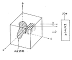
図1は、本発明の第1の実施例に係る複写機の装置概観図である。同図において、符号501はイメージスキャナ部であり、400dpi(dots/inch)の解像度で原稿を読み取り、それに対するディジタル信号処理を行なう。また、502はプリンタ部であり、イメージスキャナ部501によって読み取られた原稿画像に対応した画像を、400dpi の解像度で記録用紙上にフルカラーでプリント出力する。
【0009】
イメージスキャナ部501において、500は鏡面圧板であり、原稿台ガラス(以下、プラテンという)503上の原稿504は、ランプ505からの光で照射され、その反射光は、ミラー506,507,508に導かれる。そして、この反射光は、レンズ509によって、3ラインセンサ(以下、CCDという)510上に像を結び、フルカラー情報レッド(R),グリーン(G),ブルー(B)成分として信号処理部511に送られる。
【0010】
なお、ミラー505,506は速度vで、また、ミラー507,508は速度1/2vで、CCDの電気的走査(主走査)方向に対して垂直方向に機械的に動くことによって、原稿全面を走査(副走査)する。
信号処理部511においては、イメージスキャナ部501で読み取られた画像信号を電気的に処理し、マゼンタ(M),シアン(C),イエロー(Y),ブラック(Bk)の各成分に分解して、それをプリンタ部502に送る。また、イメージスキャナ部501における1回の原稿走査につき、M,C,Y,Bkの内、一つの成分がプリンタ部502に送られ、合計4回の原稿走査によって一回分のプリントアウトが完成する。
【0011】
イメージスキャナ部501からのM,C,Y,Bkの各画像信号は、レーザードライバ512に送られ、レーザードライバ512は、送られてきた画像信号に応じて、半導体レーザー513を変調駆動する。このレーザー光は、ポリゴンミラー514、f−θレンズ515、ミラー516を介して、感光ドラム517上を走査する。
【0012】
符号518は回転現像器であり、マゼンタ現像器519、シアン現像器520、イエロー現像器521、ブラック現像器522より構成され、これら4つの現像部が交互に感光ドラム517に接することで、感光ドラム517上に形成された静電潜像を所定のトナーで現像する。
また、符号523は転写ドラムであり、用紙カセット524(または、用紙カセット525)より供給される用紙をこの転写ドラムに巻き付け、感光ドラム517上にて現像された像を記録用紙に転写する。
【0013】
このようにして、M,C,Y,Bkの4色が順次転写された後、記録用紙は定着ユニット526を通過し、上記のトナーが用紙に定着された後、本装置外に排紙される。
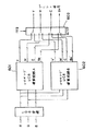
図2は、本実施例に係る複写機における信号処理系統を示すブロック図である。同図において、符号101はCCDセンサー、102はアナログ増幅器、103はA/D変換器である。また、符号104は、画像信号の読み取り位置による明るさのバラツキを補正するためのシェーディング補正回路である。なお、このシェーディング補正については公知技術であるため、ここでは詳述しない。
【0014】
符号105はプリント信号生成回路であり、R(レッド)、G(グリーン)、B(ブルー)からなる入力画像信号を、M(マゼンタ)、C(シアン)、Y(イエロー)、K(ブラック)の各信号からなるプリント信号に変換する。このプリント信号生成回路は、後述する特定原稿の判定に要する時間を補正するための遅延手段を含む。また、判定補正信号f113により、プリント信号を変調する。
【0015】
符号106は、入力画像データと、例えば、紙幣や有価証券などの特定原稿との色空間での色味の分布の類似度をリアルタイムで算出する色空間マッチング判定回路である。また、108は、読み取り同期信号HS109、CLK110、VS112を生成する読み取り同期信号回路である。これらの信号の内、HS109は主走査区間信号、CLK110は画素読み取り基本クロック信号、VS112は原稿読み取りの副走査方向の有効領域を示す区間信号である。
【0016】
さらに、符号121は、本複写機全体の制御を司るマイクロコンピューター(以下、CPUという)であり、120は、CPU121に接続される入出力ポート(以下、I/Oポートという)、122は、CPU121の制御プログラムや各種演算に要するデータを格納するためのメモリである。
図2の色空間マッチング判定回路106へ入力される面順次信号CNOは、2ビットの出力カラー選択信号であり、上述の4回の読み取り動作の順番を、以下に示す如く制御する信号である。なお、この信号CNOは、CPU121よりI/Oポート120を経て発生され、後述するマスキングUCR演算回路A601の動作条件を切り替える。
【0017】

【0018】
符号204は、複数種類の特定原稿の色味に関する情報を、図4に示すように格納する判定ROM(以下、ROMという)である。つまり、このROM204には、特定原稿について、その色味分布をあらかじめ調べ、当該画素の色味が、それらの特定原稿の色味と一致するか否かの判定結果が保持されている。そして、ROM204には、アドレスの上位2ビットに面順次信号であるCNO信号が、また、下位15ビットには、間引かれたRGB各色の画像信号の上位5ビットずつがそれぞれ入力される。
【0019】
アドレス・バスA0〜A14に、前記R,G,B信号が入力され、それらが複数種類の特定原稿それぞれの色味に合致している場合は‘1’、一致しない場合は‘0’の判定信号が、データ・バスD0〜D7のそれぞれに出力される。データ・バスD0〜D7は、第0番目から第7番目までの8種類の特定原稿に対応する。また、上記の各面順次信号CNOの値0〜3において、それぞれ入力された画素データに対して、データ・バスD0〜D7から各特定原稿に関する8種類の異なる色味判定情報が並列に出力される。
【0020】
本実施例に係る複写機では、2回のスキャンで8種類の特定原稿についての判定を行なう。以下、その方法について説明する。
まず、第1スキャンで8種類の特定原稿について判定し、第2スキャンで、異なる色味分布情報を用いて、同じ8種類の特定原稿について判定する。そして、同じ特定原稿について、第1スキャンの判定結果と第2スキャンの判定結果の論理積をとり、それを最終的な判定結果とする。
【0021】
そのため、同一の判定回路で判定する特定原稿は、スキャンにかかわらず同じものとする。つまり、図3の色空間判定回路0〜7(240〜247)で判定するのは、第1スキャンでも第2スキャンでも同じ特定原稿になるように、あらかじめROM204にデータをセットしておく。その他の7種類の特定原稿に対するデータについても同様である。
【0022】
図5,図6は、ROM204内の色味分布情報の格納状態を説明するための図である。例えば、図5に示すように、第1スキャン時に色空間判定回路5で用いる色味分布情報は‘a5’とし、同様に、第2スキャン時に色空間判定回路5で用いる色味分布情報は‘b5’とする。本実施例では、‘a5’と‘b5’は、同一の特定原稿を判定するための異なる色味分布情報であり、その他の7種類の特定原稿に対するデータについても、同様の処理を行なう。
【0023】
また、後述するように、例えば、‘a5’,‘b5’は、これらの色味分布情報を用いてなされた判定結果を格納するメモリのアドレスをも示す。よって、図5は、後述するメモリ122のアドレス・マップにそのまま対応づけられることになる。
なお、c0〜c7,d0〜d7は、本実施例では参照されないダミー・データである。
【0024】
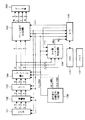
図3の符号220〜227は平滑回路0〜7であり、ROM204から出力される色味判定信号X0〜X7に対して、図7,図8で示す平滑演算を行なう。
図7は、平滑回路0〜7(220〜227)各々の内部回路構成を示すブロック図である。同図において、符号701,702は乗算器、703は加算器、704はラッチ回路、705はコンパレータである。乗算器701,702、加算器703は、入力データと前データの加重平均により、図8に示されるような連続性を加味した判定を行なう。
【0025】
図8は、平滑回路への入力Xiと平滑演算値Yiとの関係を示す図である。ここでは、図8に示すように、入力Xiの値が連続して‘1’であれば、出力Yiの値が増大する。これにより、入力信号が連続して特定原稿の色味に合致している場合には、平滑回路0〜7(220〜227)からの出力信号C0〜C7(230〜237)は‘1’となり、ノイズ等の影響を受けることなく、より正確な判定が可能となる。
【0026】
図9は、RGB色空間における特定原稿と入力画像の類似度を説明するための図である。図3に示す色空間判定回路0〜7(240〜247)では、図9に示すように、RGB色空間における特定原稿のデータと入力画像信号のデータの類似度をリアルタイムで算出し、色空間類似度判定信号MK0〜MK7を算出する。
【0027】
図10は、図3の色空間判定回路0〜7(240〜247)各々の内部回路構成を示すブロック図である。同図に示す判定回路では、SRAM209からのデータDnと、平滑回路220〜227からの信号Cnとが論理和(OR)演算され(n=0〜7)、その結果がSRAM209に書き込まれる。
また、データDnが‘0’から‘1’へ遷移する場合にのみ、10ビットカウンタ301が加算される。このカウンタ301は、副走査区間信号VS112の立ち上りでクリアされ、カウンタ301の出力値Znと、レジスタ303からの定数δnとがコンパレータ302で大小比較される。その結果、Zn>δnの場合、MKn=1となり、Zn≦δnの場合、MKn=0となる。
【0028】
なお、δnの値は、図9において斜線部にて示されるUorgのL%の値(本実施例では、L=70)が設定されている。すなわち、
δn=Uorg×L/100 …(1)
であり、Uorgは、図9において、R,G,B各々の座標軸について、それを32に区分した長さを一辺とした立方体を単位体積とする値である。
【0029】
このように、色空間判定回路0〜7では、上記の処理により、RGB色空間で、入力画像信号の色味の分布が特定原稿の色味の分布とほぼ同一の形状となったとき、色空間類似度判定信号であるMKnが‘1’に設定される。
CPU121は、色空間類似度判定信号である上記のMKnに応じて、判定補正信号f113を‘1’(論理High)、または‘0’(論理Low)に設定する。なお、この動作については後述する。
【0030】
図3のセレクタ271,272は、副走査区間信号VS112が‘0’のとき、SRAM209の内容をゼロ・クリアする。また、アドレス・ジェネレータ270は、SRAM209の全てのアドレスを順に発生する回路である。つまり、信号VS112が‘0’のとき、アドレス・ジェネレータ270が発生するアドレス信号に従って、SRAM209が‘0’にクリアされる。
【0031】
また、タイミング発生回路205は、図11,図12のタイミングチャートに示すようなタイミング信号を発生する。同図において、CLK4(206)は基本クロックCLK110を4分周したクロック信号であり、信号207は、SRAM209のライト・イネーブル(WE)端子を制御する信号である。また、信号208は、SRAM209のアウトプット・イネーブル(OE)端子を制御する信号である。
【0032】
図13は、図2のプリント信号生成回路105の内部回路構成を示すブロック図である。同図において、マスキングUCR演算回路A601は、通常時は、入力されたRGB信号よりプリントYMCK信号を生成する回路である。このマスキングUCR演算回路Aは、面順次信号CNOの値により信号生成の条件を変える。また、マスキングUCR演算回路B602は、入力画像信号が特定原稿に合致すると判定された場合、色味を変えた(例えば、赤みを強くした)プリントYMCK信号を生成する回路である。
【0033】
そして、セレクタ603が、CPU121からの判定補正信号f113によって、マスキングUCR演算回路601,602の出力信号を選択し、出力することにより、色味を変えてプリントアウトすることが可能となる。
本実施例では、入力された画像データが特定原稿に類似していると判定された場合には、再生画像をベタ黒で塗りつぶしたり、複写機の電源をオフにするなど、正常な像形成が行なえないようにしている。
【0034】
次に、本実施例に係る複写機にて、CPU121が、判定補正信号f113を‘1’、または‘0’に設定する手順について詳細に説明する。
図14,図15は、CPU121が判定補正信号f113を‘1’または‘0’に設定する手順を示すフローチャートである。
図14において、本実施例に係る複写機にてコピーが開始されると、CPU121は、まず、メモリ122の内容をゼロ・クリアする(ステップS1)。そして、判定補正信号f113を‘0’(Low)にセット後(ステップS2)、上述の第1スキャンを行なう(ステップS3)。
【0035】
図15は、このスキャン処理手順を示すフローチャートである。すなわち、スキャンが開始されると、色空間マッチング判定回路106(図2参照)に画像信号が入力される(ステップS9)。そして、その入力信号について判定処理が成される(ステップS10)。
上述の色空間類似度判定信号MKn(n=0〜7)の内、いずれか一つでも‘1’であるときには(ステップS11での判定がYes)、メモリ122の対応するアドレスの領域に‘1’を格納する。このメモリ122のアドレスを、図16に示す。例えば、第1スキャンにおいて、判定信号MK5=‘1’の場合には、アドレスa5の領域に‘1’が格納されることになる。また、色空間類似度判定信号MKnのすべてが‘0’のときには(ステップS11での判定結果がNo)、何ら処理を行なわない。
【0036】
ステップS13では、スキャンが終了しているか否かの判定が行なわれ、スキャンが終わっていない場合には、次の画素にあたる画像信号を色空間マッチング判定回路106に入力するという処理、すなわち、再度、ステップS9の処理に戻る。一方、スキャンが終了したと判断されたならば(ステップS13でYes)、第2のスキャンを行なう。
【0037】
本実施例における第2スキャンに関する手順(図14のステップS4)は、上記の第1スキャンの手順とほぼ同じなので、ここでは詳述しない。第1のスキャンと第2のスキャンとの相違点は、判定結果を格納するメモリ122のアドレスのみであり、MKn(n=0〜7)に対応するのは、bn(n=0〜7)である。
【0038】
ステップS4での第2スキャン終了後、ステップS5で、上記のスキャン毎の判定結果の同じ特定原稿に関するものの論理積をとり、特定原稿8種類の内、1種類でも、その結果が‘真’ならば(ステップS5の判定がYes)、CPU121は、判定補正信号f113を‘1’(High)とする(ステップS6)。また、判定結果が‘偽’ならば(ステップS5でNo)、‘0’(Low)のままとする。
【0039】
これらの関係を式で表わすと、以下のようになる。すなわち、
【0040】
上記の処理の後、第3スキャン(ステップS7)、第4スキャン(ステップS8)を行ない、コピー処理を終了する。ここでは、上述の処理にて特定原稿を判定した場合、第3スキャン、第4スキャンで、通常と異なるプリント条件でのコピー、例えば、上記のように、再生画像をベタ黒で塗りつぶしたり、複写機の電源をオフにするなど、正常な像形成が行なえない処理を行なう。
【0041】
以上説明したように、本実施例によれば、1回目のスキャンで得られた特定原稿についての色味分布情報を用いて2回目のスキャンで同一の特定原稿の判定を行なうことで、つまり、スキャン順序とは無関係に同一判定回路で同じ特定原稿についての判定を行なうことで、色味情報を格納するメモリの容量を増加させずに、判定できる特定原稿の種類を増やすことができる。
[第2実施例]
以下、本発明に係る第2の実施例を説明する。なお、本実施例に係る複写機は、その構成及び信号処理系統が上記第1実施例に係る複写機と同一であるため、ここではその説明を省略する。また、ここでは、図17に示すような3種類の紙幣の表と裏、すなわち、計6種類の特定原稿を判定対象とする場合を考える。
【0042】
図17に示すように、紙幣の表として3種類、裏として3種類の特定原稿が、共通部分としてその中央に赤い模様及び茶色い模様を有する。本実施例では、これらの模様を共通の色味分布情報により判定し、その判定結果と、それぞれの原稿が持つ特徴的な部分の判定との論理積をとる。
図18は、本実施例に係るROM204に格納された色味分布情報の配置を示す。同図において、例えば、黄0〜黄3は、図17の特定原稿Aの黄色部分を判定するための4つの色味分布情報、青赤0〜青赤3は、特定原稿Fの青/赤色部分を判定するための4つの色味分布情報、また、赤0〜赤3は、特定原稿A,C,Eの中央の赤色部分を判定するための4つの色味分布情報をそれぞれ示す。
【0043】
図19,図20は、本実施例に係るCPU121が、判定補正信号f113を‘1’、または‘0’に設定する手順を示すフローチャートである。すなわち、本実施例に係るCPU121は、同図に示す手順に従って、判定補正信号f113を‘1’(High)、または‘0’(Low)に設定する。
図19において、コピーが開始されると、CPU121はメモリ122をゼロ・クリアする(ステップS20)。そして、判定補正信号f113を‘0’(Low)にセットする(ステップS21)。続いて、第1スキャンの実行(ステップS22)、第2スキャンの実行(ステップS23)、第3スキャンを実行する(ステップS24)。なお、これらのスキャンの実行手順は、図15に示す、上記第1の実施例と同じであるため、ここでは詳述しない。
【0044】
本実施例では、ステップS25での第4スキャンは、そのスキャン中に判定補正信号f113が変更される可能性があるため、上記の他のスキャンとは制御が異なる。
図20は、本実施例に係る第4スキャンの手順を示すフローチャートである。すなわち、第4スキャンが開始されると、色空間マッチング判定回路106に画像信号が入力され(ステップS26)、その画像信号についての判定処理が成される(ステップS27)。
【0045】
そして、色空間判定回路から出力される色空間類似度判定信号MKn(n=0〜7)の内、いずれか一つでも‘1’である場合には(ステップS28での判定がYes)、演算処理の実行、すなわち、メモリ122の対応するアドレスの領域に‘1’を格納し、他のスキャン時の判定結果の同じ特定原稿に関するものとの論理積をとる(ステップS29)。
【0046】
図18に示す色味分布情報の配置に対応するメモリ122のアドレスを用いて、判定補正信号f113の値を決める論理演算を式にて表わすと、以下のようになる。すなわち、
【0047】
上記演算の結果が‘真’ならば(ステップS2でYes)、判定補正信号f113を‘1’(High)とする(ステップS30)が、結果が‘偽’ならば(ステップS29でNo)、f113を‘0’(Low)とする(ステップS31)。そして、ステップS32で、スキャンが終了していないと判定されたならば、次の画素にあたる画像信号を色空間マッチング判定回路106に入力するという処理、すなわち、再度、ステップS26の処理に戻る。
【0048】
一方、スキャンが終了したと判定されたならば(ステップS32でYes)、本コピー処理を終了する。
以上説明したように、本実施例によれば、複数のスキャン動作間にまたがって特定原稿の判定結果についての演算を実行し、複数の特定原稿に共通な部分については1度のスキャン動作で判定結果を出すことで、メモリ内に保持する色味分布情報を制限することができ、正確な画像の判定を行なうことができる。
[第3の実施例]
上記第1及び第2の実施例においては、色空間類似度判定信号MKnは2値であるが、本発明はこれに限定されず、判定信号MKnは多値であってもよい。
【0049】
図21は、本実施例に係る複写機を構成する色空間判定回路の構成を示すブロック図である。なお、ここでは、図10に示す、上記第1実施例に係る色空間判定回路と同一構成要素には同一符号を付し、それらについては詳述しない。
図21に示す本実施例に係る色空間判定回路では、カウンタ301の出力値Znと、レジスタ303からの定数δnとが除算器310で除算され、色空間類似度判定信号MKnは、5ビット長の値として出力される。なお、定数δnの値は、図9に示す体積Uorgの32分の1の値が設定されている。
【0050】
上記の処理により、入力画像信号の色味の分布と、特定原稿の色味の分布とのRGB色空間上での分布形状の類似度が、色空間類似度判定信号であるMknにより5ビット長の多値データとして表わされる。
図22は、本実施例に係る色空間マッチング判定回路の信号処理ブロック図である。ここでは、図2に示された、上記第1実施例に係る色空間マッチング判定回路と同一構成部分については詳述しない。
【0051】
図22に示す色空間マッチング判定回路と図2に示す色空間マッチング判定回路との異なる点は、本実施例に係る色空間マッチング判定回路では、色空間マッチング判定回路106からI/Oポート120に色空間類似度判定信号MKnを伝える信号線のバス幅が、40ビットになっている点のみである。
そして、上記第2の実施例で用いた判定対象となる特定紙幣について、本実施例では、色空間類似度判定信号MKnが多値になったことを加味して、判定補正信号f113の値を決める論理演算式は、以下のようになる。すなわち、
【0052】
そして、上記の式(4)において、しきい値s1,s2を適切に設定することにより、入力画像信号の色味の分布と特定原稿の色味の分布との、RGB色空間上での分布形状の類似度を多値で判定する。
以上説明したように、本実施例によれば、色空間類似度判定信号を多値とすることで、よりロバストな特定原稿の判定が可能となる。
【0053】
なお、本発明は、複数の機器から構成されるシステムに適用しても1つの機器から成る装置に適用しても良い。また、本発明は、システムあるいは装置にプログラムを供給することによって達成される場合にも適用できることは言うまでもない。
【0054】
【発明の効果】
以上説明したように、本発明によれば、複数種類の特定原稿の色味分布情報を用いることで、特定原稿の判定の自由度が向上し、かつ、判定条件が厳しくなるので判定精度が向上する。
【図面の簡単な説明】
【図1】本発明の第1の実施例に係る複写機の装置概観図である。
【図2】第1実施例に係る複写機における信号処理系統を示すブロック図である。
【図3】色空間マッチング判定回路106の内部構成を示すブロック図である。
【図4】ROM204の色味分布情報の格納方法を説明するための図である。
【図5】ROM204内の色味分布情報の格納状態を説明するための図である。
【図6】ROM204内の色味分布情報の格納状態を説明するための図である。
【図7】平滑回路0〜7の内部回路構成を示すブロック図である。
【図8】入力Xiと平滑演算値Yiとの関係を示す図である。
【図9】RGB色空間における特定原稿と入力画像の類似度を説明するための図である。
【図10】図3の色空間判定回路0〜7の内部回路構成を示すブロック図である。
【図11】タイミング発生回路205にて発生されるタイミング信号のタイミングチャートである。
【図12】タイミング発生回路205にて発生されるタイミング信号のタイミングチャートである。
【図13】図2のプリント信号生成回路105の内部回路構成を示すブロック図である。
【図14】CPU121が判定補正信号f113を‘1’または‘0’に設定する手順を示すフローチャートである。
【図15】CPU121が判定補正信号f113を‘1’または‘0’に設定する手順を示すフローチャートである。
【図16】メモリ122のアドレスマップを示す図である。
【図17】第2実施例に係る特定原稿の判定対象なる3種類の紙幣の表と裏を示す図である。
【図18】第2実施例に係るROM204に格納された色味分布情報の配置を示す図である。
【図19】第2実施例に係るCPU121が、判定補正信号f113を‘1’、または‘0’に設定する手順を示すフローチャートである。
【図20】第2実施例に係るCPU121が、判定補正信号f113を‘1’、または‘0’に設定する手順を示すフローチャートである。
【図21】第3実施例に係る複写機を構成する色空間判定回路の構成を示すブロック図である。
【図22】第3の実施例における色空間マッチング判定回路のブロック図である。
【符号の説明】
101 CCDセンサー
102 アナログ増幅器
103 A/D変換器
104 シェーディング補正回路
105 プリント信号生成回路
106 色空間マッチング判定回路
108 読み取り同期信号回路
120 入出力ポート(I/Oポート)
121 マイクロコンピューター(CPU)
122 メモリ[0001]
[Industrial applications]
The present invention relates to an image processing apparatus and a method for detecting a specific document.
[0002]
[Prior art]
In recent years, with the performance improvement of color copiers and color printers, illegal use of these devices has become a problem. That is, there is a problem that these devices are used for counterfeiting bills, securities, and the like. Therefore, there is a need for a technique for preventing the copying of a specific document.
[0003]
As one of the techniques, the distribution information of the color of a specific document in the color space is registered in advance, and by comparing the distribution information with the distribution of the color of the input image data, the input image data can be obtained. It has been proposed by the applicant of the present invention to determine whether or not a document is a specific document (Japanese Patent Application No. 3-160384).
[0004]
[Problems to be solved by the invention]
However, the above-described conventional specific document determination method has a problem that the type of the specific document to be determined, that is, the number of color distribution information to be registered in advance in a color copying machine or a color printer is large. And even if it is limited to banknotes alone, the types of banknotes to be registered are excellent, given the difference in design between the front and back, and the necessity of dealing with banknotes in neighboring countries, especially in Europe. More than a dozen types.
[0005]
In addition, in order to improve the determination rate of a specific document, it is desirable to make a determination using a plurality of color distribution information for one type of specific document, and the determination conditions become strict. It can be said that the larger the number of pieces of color distribution information to be used, the better.
[0006]
SUMMARY OF THE INVENTION The present invention has been made to solve the above problem, and has as its object to improve the degree of freedom and accuracy of determination of a specific document.
[0007]
[Means for Solving the Problems]
The present invention has the following configuration as one means for achieving the above object. An image processing apparatus according to the present invention is an image processing apparatus that performs predetermined image processing on an image signal obtained by optically scanning a document a plurality of times and visually outputs an image after the image processing. Means for storing in advance color distribution information on a specific document of a type, and, in the plurality of scans, color distribution information common to a pattern which a plurality of types of specific documents have as a common portion and the image signal. First determining means for determining a first similarity; and a second similarity between the image signal and the tint distribution information of characteristic portions of a plurality of types of specific originals in the plurality of scans. Based on a logical product and a logical sum of the first and second similarities and a result obtained by a combination of the logical product and the logical sum. Similarity with certain manuscripts Characterized in that it comprises a third determining means for determining. Further, in an image processing apparatus that performs predetermined image processing on an image signal obtained by optically scanning an original a plurality of times and visually outputs the image after the image processing, a color distribution of a plurality of types of specific originals is provided. Means for storing information in advance, and in the plurality of scans, determine a first similarity between color distribution information and the image signal common to patterns having a plurality of types of specific documents as a common portion, A first determination unit that outputs the determination result as multi-valued information; and, in the plurality of scans, a second comparison between the color distribution information of the characteristic portions of each of the plurality of types of specific originals and the image signal. A second determining unit that determines a similarity and outputs a result of the determination as multi-valued information; and, based on the first and second similarities, determines a similarity between the document and the plurality of types of specific documents. Third determining means for determining Characterized in that it comprises a. An image processing method according to the present invention is an image processing method of an image processing apparatus that performs predetermined image processing on an image signal obtained by optically scanning a document and visually outputs an image after the image processing. The color information about a plurality of types of specific documents is stored in a memory in advance, and in the scanning, the first similarity between the color information common to the patterns that the plurality of types of specific documents have as a common part and the image signal is determined. In the scanning, a second similarity between the color information of the characteristic portion of each of the plurality of types of specific originals and the image signal is determined, and a logic of the first and second similarities is determined. The similarity between the document and the plurality of types of specific documents is determined based on a product, a logical sum, and a result obtained by a combination of the logical product and the logical sum. An image processing method of an image processing apparatus for performing predetermined image processing on an image signal obtained by optically scanning an original and outputting the image after the image processing in a visible manner. The color information is stored in a memory in advance, and in the scanning, a first similarity between the color information common to the patterns included in the plurality of types of specific originals as a common portion and the image signal is determined, and the determination result is determined. Output as multi-valued information, and in the scanning, determine the second similarity between the color information and the image signal of a characteristic portion of each of a plurality of types of specific documents, and use the determination result as multi-valued information. And outputting a similarity between the original and the plurality of types of specific originals based on the first and second similarities.
[0008]
【Example】
Hereinafter, preferred embodiments of the present invention will be described in detail with reference to the accompanying drawings. In the following embodiments, the present invention is applied to a copying machine, but the present invention is not limited to this, and it goes without saying that the present invention can be applied to various other apparatuses.
[First embodiment]
FIG. 1 is a schematic view of a copying machine according to a first embodiment of the present invention. In the figure,
[0009]
In the
[0010]
Note that the
The
[0011]
Each of the M, C, Y, and Bk image signals from the
[0012]
[0013]
After the four colors M, C, Y, and Bk are sequentially transferred in this manner, the recording sheet passes through the fixing
FIG. 2 is a block diagram illustrating a signal processing system in the copying machine according to the present embodiment. In the figure,
[0014]
[0015]
[0016]
The frame sequential signal CNO input to the color space
[0017]
[0018]
[0019]
The R, G, and B signals are input to the address buses A0 to A14. If the R, G, and B signals match the colors of a plurality of types of specific originals, the judgment is "1". A signal is output to each of data buses D0 to D7. The data buses D0 to D7 correspond to eight types of specific originals from the 0th to the 7th. In addition, for the
[0020]
In the copying machine according to the present embodiment, the determination about eight types of specific originals is performed by two scans. Hereinafter, the method will be described.
First, eight types of specific documents are determined in the first scan, and the same eight types of specific documents are determined in the second scan using different color distribution information. Then, for the same specific document, a logical product of the determination result of the first scan and the determination result of the second scan is obtained, and the result is used as the final determination result.
[0021]
Therefore, the specific documents determined by the same determination circuit are the same regardless of scanning. In other words, data to be determined by the color
[0022]
FIGS. 5 and 6 are diagrams for explaining the storage state of the tint distribution information in the
[0023]
Further, as will be described later, for example, 'a5' and 'b5' also indicate addresses of a memory for storing a determination result made using the color distribution information. Therefore, FIG. 5 is directly associated with an address map of the
Note that c0 to c7 and d0 to d7 are dummy data not referred to in the present embodiment.
[0024]
FIG. 7 is a block diagram showing the internal circuit configuration of each of the smoothing
[0025]
FIG. 8 is a diagram illustrating the relationship between the input Xi to the smoothing circuit and the smoothed operation value Yi. Here, as shown in FIG. 8, if the value of the input Xi is “1” continuously, the value of the output Yi increases. Accordingly, when the input signal continuously matches the color of the specific document, the output signals C0 to C7 (230 to 237) from the smoothing
[0026]
FIG. 9 is a diagram for explaining the similarity between a specific document and an input image in the RGB color space. The color
[0027]
FIG. 10 is a block diagram showing the internal circuit configuration of each of the color
Also, the 10-
[0028]
Note that the value of δn is set to the value of L% of Uorg (L = 70 in this embodiment) indicated by the hatched portion in FIG. That is,
δn = Uorg × L / 100 (1)
In FIG. 9, Uorg is a value in which a unit volume is a cube whose length is divided into 32 sides of each of the R, G, and B coordinate axes in FIG.
[0029]
As described above, in the color
The
[0030]
The
[0031]
The timing generation circuit 205 generates a timing signal as shown in the timing charts of FIGS. In the figure, CLK4 (206) is a clock signal obtained by dividing the basic clock CLK110 by 4, and a signal 207 is a signal for controlling the write enable (WE) terminal of the
[0032]
FIG. 13 is a block diagram showing an internal circuit configuration of the print
[0033]
Then, the
In the present embodiment, when it is determined that the input image data is similar to the specific document, normal image formation is performed by, for example, filling the reproduced image with solid black or turning off the copier. I do not do it.
[0034]
Next, a procedure in which the
FIGS. 14 and 15 are flowcharts showing a procedure in which the
In FIG. 14, when copying is started in the copying machine according to the present embodiment, the
[0035]
FIG. 15 is a flowchart showing the scan processing procedure. That is, when scanning is started, an image signal is input to the color space matching determination circuit 106 (see FIG. 2) (step S9). Then, a determination process is performed on the input signal (step S10).
When any one of the above-described color space similarity determination signals MKn (n = 0 to 7) is “1” (the determination in step S11 is Yes), “ 1 'is stored. The addresses of the
[0036]
In step S13, it is determined whether or not the scan has been completed. If the scan has not been completed, a process of inputting an image signal corresponding to the next pixel to the color space
[0037]
The procedure for the second scan (step S4 in FIG. 14) in this embodiment is almost the same as the procedure for the above-described first scan, and thus will not be described in detail here. The only difference between the first scan and the second scan is the address of the
[0038]
After the end of the second scan in step S4, in step S5, the logical product of the above-described determination results for each scan relating to the same specific document is obtained. If it is (the determination in step S5 is Yes), the
[0039]
These relationships can be expressed as follows. That is,
[0040]
After the above processing, a third scan (step S7) and a fourth scan (step S8) are performed, and the copy processing ends. Here, when the specific document is determined in the above-described processing, the third scan and the fourth scan copy under a print condition different from normal, for example, as described above, the reproduced image is filled with solid black or copied. Performs processing that cannot perform normal image formation, such as turning off the power of the apparatus.
[0041]
As described above, according to the present embodiment, the same specific document is determined in the second scan using the color distribution information on the specific document obtained in the first scan, that is, By performing the determination on the same specific document by the same determination circuit irrespective of the scanning order, it is possible to increase the types of specific documents that can be determined without increasing the capacity of the memory for storing the color information.
[Second embodiment]
Hereinafter, a second embodiment according to the present invention will be described. The configuration and the signal processing system of the copying machine according to the present embodiment are the same as those of the copying machine according to the first embodiment, and a description thereof will be omitted. Here, a case is considered in which the front and back of three types of banknotes as shown in FIG. 17, that is, a total of six types of specific originals are to be determined.
[0042]
As shown in FIG. 17, three types of specific originals as the front and three types of the back of the banknote have a red pattern and a brown pattern at the center as a common part. In the present embodiment, these patterns are determined based on common color distribution information, and the logical product of the determination result and the determination of a characteristic portion of each document is obtained.
FIG. 18 shows an arrangement of the tint distribution information stored in the
[0043]
FIG. 19 and FIG. 20 are flowcharts illustrating a procedure in which the
In FIG. 19, when copying is started, the
[0044]
In the present embodiment, the control of the fourth scan in step S25 is different from that of the other scans described above because the determination correction signal f113 may be changed during the scan.
FIG. 20 is a flowchart illustrating the procedure of the fourth scan according to the present embodiment. That is, when the fourth scan is started, an image signal is input to the color space matching determination circuit 106 (step S26), and a determination process for the image signal is performed (step S27).
[0045]
If any one of the color space similarity determination signals MKn (n = 0 to 7) output from the color space determination circuit is “1” (the determination in step S28 is Yes), Execution of the arithmetic processing, that is, '1' is stored in the area of the corresponding address of the
[0046]
A logical operation for determining the value of the determination correction signal f113 using the address of the
[0047]
If the result of the above operation is "true" (Yes in step S2), the judgment correction signal f113 is set to "1" (High) (step S30). If the result is "false" (no in step S29), f113 is set to '0' (Low) (step S31). If it is determined in step S32 that the scanning has not been completed, the process returns to the process of inputting the image signal corresponding to the next pixel to the color space
[0048]
On the other hand, if it is determined that the scanning has been completed (Yes in step S32), the main copying process is completed.
As described above, according to the present embodiment, the calculation of the determination result of the specific document is performed over a plurality of scanning operations, and the portion common to the plurality of specific documents is determined by one scanning operation. By providing the result, the color distribution information held in the memory can be limited, and accurate image determination can be performed.
[Third embodiment]
In the first and second embodiments, the color space similarity determination signal MKn is binary, but the present invention is not limited to this, and the determination signal MKn may be multi-valued.
[0049]
FIG. 21 is a block diagram illustrating a configuration of a color space determination circuit included in the copying machine according to the present embodiment. Here, the same components as those of the color space determination circuit according to the first embodiment shown in FIG. 10 are denoted by the same reference numerals, and will not be described in detail.
In the color space determination circuit according to this embodiment shown in FIG. 21, the output value Zn of the
[0050]
According to the above-described processing, the similarity of the distribution shape in the RGB color space between the distribution of the tint of the input image signal and the distribution of the tint of the specific document is determined by the color space similarity determination signal Mkn, which has a 5-bit length. Is represented as multi-valued data.
FIG. 22 is a signal processing block diagram of the color space matching determination circuit according to the present embodiment. Here, the same components as those of the color space matching determination circuit according to the first embodiment shown in FIG. 2 will not be described in detail.
[0051]
The difference between the color space matching determination circuit shown in FIG. 22 and the color space matching determination circuit shown in FIG. 2 is that in the color space matching determination circuit according to the present embodiment, the color space
In this embodiment, the value of the judgment correction signal f113 is changed for the specific banknote to be judged used in the second embodiment in consideration of the fact that the color space similarity judgment signal MKn has become multi-valued. The logical operation expression to be determined is as follows. That is,
[0052]
In the above equation (4), by appropriately setting the threshold values s1 and s2, the distribution of the color of the input image signal and the color of the specific document in the RGB color space is obtained. The shape similarity is determined by multi-value.
As described above, according to the present embodiment, by making the color space similarity determination signal multi-valued, a more robust determination of a specific document can be made.
[0053]
The present invention may be applied to a system including a plurality of devices or an apparatus including one device. Needless to say, the present invention can be applied to a case where the present invention is achieved by supplying a program to a system or an apparatus.
[0054]
【The invention's effect】
As described above, according to the present invention, by using the color distribution information of a plurality of types of specific documents, the degree of freedom in determining the specific document is improved, and the determination conditions are strict, so that the determination accuracy is improved. I do.
[Brief description of the drawings]
FIG. 1 is a schematic view of an apparatus of a copying machine according to a first embodiment of the present invention.
FIG. 2 is a block diagram illustrating a signal processing system in the copying machine according to the first embodiment.
FIG. 3 is a block diagram showing an internal configuration of a color space
FIG. 4 is a diagram for explaining a method of storing color distribution information in a
FIG. 5 is a diagram for explaining a storage state of color distribution information in a
FIG. 6 is a diagram for explaining a storage state of color distribution information in a
FIG. 7 is a block diagram illustrating an internal circuit configuration of smoothing
FIG. 8 is a diagram showing a relationship between an input Xi and a smoothed operation value Yi.
FIG. 9 is a diagram for explaining the similarity between a specific document and an input image in an RGB color space.
FIG. 10 is a block diagram showing an internal circuit configuration of color
11 is a timing chart of a timing signal generated by a timing generation circuit 205. FIG.
12 is a timing chart of a timing signal generated by a timing generation circuit 205. FIG.
FIG. 13 is a block diagram illustrating an internal circuit configuration of the print
FIG. 14 is a flowchart illustrating a procedure in which a
FIG. 15 is a flowchart illustrating a procedure in which a
FIG. 16 is a diagram showing an address map of a
FIG. 17 is a diagram showing the front and back of three types of banknotes to be determined for a specific document according to the second embodiment.
FIG. 18 is a diagram showing an arrangement of color distribution information stored in a ROM according to a second embodiment.
FIG. 19 is a flowchart illustrating a procedure in which the
FIG. 20 is a flowchart illustrating a procedure in which the
FIG. 21 is a block diagram illustrating a configuration of a color space determination circuit included in a copying machine according to a third embodiment.
FIG. 22 is a block diagram of a color space matching determination circuit according to the third embodiment.
[Explanation of symbols]
101 CCD sensor
102 Analog amplifier
103 A / D converter
104 Shading correction circuit
105 Print signal generation circuit
106 Color space matching judgment circuit
108 Read sync signal circuit
120 I / O port (I / O port)
121 Microcomputer (CPU)
122 memory
Claims (6)
複数種類の特定原稿についての色味分布情報を予め記憶しておく手段と、
前記複数回の走査において、複数種類の特定原稿が共通部分として有する模様に共通の色味分布情報と前記画像信号との第一の類似度を判定する第一の判定手段と、
前記複数回の走査において、複数種類の特定原稿がそれぞれもつ特徴的な部分の色味分布情報と前記画像信号との第二の類似度を判定する第二の判定手段と、
前記第一および第二の類似度についての論理積、論理和、および該論理積と論理和の組み合わせによって得られる結果に基づいて、前記原稿と前記複数種類の特定原稿との類似度を判定する第三の判定手段とを備えることを特徴とする画像処理装置。An image processing apparatus that performs predetermined image processing on an image signal obtained by optically scanning a document a plurality of times and visually outputs an image after the image processing,
Means for storing in advance color distribution information for a plurality of types of specific originals;
In the plurality of scans, a first determination unit that determines a first similarity between the image signal and color distribution information common to patterns having a plurality of types of specific documents as a common portion,
In the plurality of scans, a second determination unit that determines a second similarity between the image signal and the tint distribution information of a characteristic portion of each of a plurality of types of specific documents,
A similarity between the document and the plurality of types of specific documents is determined based on a logical product and a logical sum of the first and second similarities and a result obtained by a combination of the logical product and the logical sum. An image processing apparatus comprising: a third determination unit.
複数種類の特定原稿についての色味分布情報を予め記憶しておく手段と、
前記複数回の走査において、複数種類の特定原稿が共通部分として有する模様に共通の色味分布情報と前記画像信号との第一の類似度を判定し、その判定結果を多値情報として出力する第一の判定手段と、
前記複数回の走査において、複数種類の特定原稿がそれぞれもつ特徴的な部分の色味分布情報と前記画像信号との第二の類似度を判定し、その判定結果を多値情報として出力する第二の判定手段と、
前記第一および第二の類似度に基づいて、前記原稿と前記複数種類の特定原稿との類似度を判定する第三の判定手段とを備えることを特徴とする画像処理装置。 An image processing apparatus that performs predetermined image processing on an image signal obtained by optically scanning a document a plurality of times and visually outputs an image after the image processing,
Means for storing in advance color distribution information for a plurality of types of specific originals;
In the plurality of scans, a first similarity between the color distribution information common to the patterns of a plurality of types of specific documents as a common portion and the image signal is determined, and the determination result is output as multi-valued information. First determining means;
In the plurality of scans, a second similarity between the color distribution information of a characteristic portion of each of a plurality of types of specific documents and the image signal is determined, and the determination result is output as multi-valued information. Two determination means,
An image processing apparatus comprising: a third determination unit configured to determine a similarity between the document and the plurality of types of specific documents based on the first and second similarities .
複数種類の特定原稿についての色味情報を予めメモリに記憶し、Color information about a plurality of types of specific originals is stored in a memory in advance,
前記走査において、複数種類の特定原稿が共通部分として有する模様に共通の色味情報と前記画像信号との第一の類似度を判定し、In the scanning, determine a first similarity between the color information and the image signal common to the pattern having a plurality of types of specific documents as a common portion,
前記走査において、複数種類の特定原稿がそれぞれもつ特徴的な部分の色味情報と前記画像信号との第二の類似度を判定し、In the scanning, determine the second similarity between the color information and the image signal of a characteristic portion of each of a plurality of types of specific document,
前記第一および第二の類似度についての論理積、論理和、および該論理積と論理和の組み合わせによって得られる結果に基づいて、前記原稿と前記複数種類の特定原稿との類似度を判定することを特徴とする画像処理方法。A similarity between the document and the plurality of types of specific documents is determined based on a logical product and a logical sum of the first and second similarities and a result obtained by a combination of the logical product and the logical sum. An image processing method comprising:
複数種類の特定原稿についての色味情報を予めメモリに記憶し、
前記走査において、複数種類の特定原稿が共通部分として有する模様に共通の色味情報と前記画像信号との第一の類似度を判定し、その判定結果を多値情報として出力し、
前記走査において、複数種類の特定原稿がそれぞれもつ特徴的な部分の色味情報と前記画像信号との第二の類似度を判定し、その判定結果を多値情報として出力し、
前記第一および第二の類似度に基づいて、前記原稿と前記複数種類の特定原稿との類似度を判定することを特徴とする画像処理方法。An image processing method of an image processing apparatus that performs predetermined image processing on an image signal obtained by optically scanning an original and visually outputs an image after the image processing,
Color information about a plurality of types of specific documents is stored in a memory in advance,
In the scanning, determine the first similarity between the color signal and the image signal common to the pattern having a plurality of types of specific document as a common portion, and output the determination result as multi-valued information,
In the scanning, the second similarity between the color information and the image signal of the characteristic portion of each of a plurality of types of specific documents is determined, and the determination result is output as multi-valued information.
An image processing method, wherein a similarity between the original and the plurality of types of specific originals is determined based on the first and second similarities.
Priority Applications (2)
| Application Number | Priority Date | Filing Date | Title |
|---|---|---|---|
| JP05626394A JP3566334B2 (en) | 1994-03-25 | 1994-03-25 | Image processing apparatus and method |
| US08/411,217 US5933520A (en) | 1994-03-25 | 1995-03-27 | Image processing apparatus |
Applications Claiming Priority (1)
| Application Number | Priority Date | Filing Date | Title |
|---|---|---|---|
| JP05626394A JP3566334B2 (en) | 1994-03-25 | 1994-03-25 | Image processing apparatus and method |
Related Child Applications (1)
| Application Number | Title | Priority Date | Filing Date |
|---|---|---|---|
| JP2000183352A Division JP2001028688A (en) | 2000-01-01 | 2000-06-19 | Image processing unit and its method |
Publications (2)
| Publication Number | Publication Date |
|---|---|
| JPH07264419A JPH07264419A (en) | 1995-10-13 |
| JP3566334B2 true JP3566334B2 (en) | 2004-09-15 |
Family
ID=13022199
Family Applications (1)
| Application Number | Title | Priority Date | Filing Date |
|---|---|---|---|
| JP05626394A Expired - Fee Related JP3566334B2 (en) | 1994-03-25 | 1994-03-25 | Image processing apparatus and method |
Country Status (2)
| Country | Link |
|---|---|
| US (1) | US5933520A (en) |
| JP (1) | JP3566334B2 (en) |
Cited By (6)
| Publication number | Priority date | Publication date | Assignee | Title |
|---|---|---|---|---|
| WO2010113987A1 (en) | 2009-03-30 | 2010-10-07 | Ricoh Company, Ltd. | Spectral characteristic obtaining apparatus, image evaluation apparatus and image forming apparatus |
| EP2320205A1 (en) | 2009-11-04 | 2011-05-11 | Ricoh Company, Ltd | Spectrometric measurement apparatus, image evaluation apparatus, and image forming apparatus |
| EP2365304A2 (en) | 2010-03-11 | 2011-09-14 | Ricoh Company, Ltd. | Spectroscopic characteristics acquisition unit, image evaluation unit, and image forming apparatus |
| US8964176B2 (en) | 2012-03-09 | 2015-02-24 | Ricoh Company, Ltd. | Spectrometer, and image evaluating unit and image forming device incorporating the same |
| US9197761B2 (en) | 2013-08-15 | 2015-11-24 | Ricoh Company, Ltd. | Spectral characteristic acquisition apparatus, image evaluation apparatus, and image forming apparatus |
| US9224080B2 (en) | 2014-02-20 | 2015-12-29 | Ricoh Company, Ltd. | Spectral characteristic acquisition device, image evaluation device, and image formation apparatus |
Families Citing this family (12)
| Publication number | Priority date | Publication date | Assignee | Title |
|---|---|---|---|---|
| US5822436A (en) | 1996-04-25 | 1998-10-13 | Digimarc Corporation | Photographic products and methods employing embedded information |
| US9630443B2 (en) | 1995-07-27 | 2017-04-25 | Digimarc Corporation | Printer driver separately applying watermark and information |
| JP4035271B2 (en) * | 1999-12-27 | 2008-01-16 | キヤノン株式会社 | Information transmitting device, information receiving device, control method thereof, storage medium and system |
| US7142689B2 (en) * | 2000-01-31 | 2006-11-28 | Canon Kabushiki Kaisha | Image processing apparatus for determining specific images |
| GB0025096D0 (en) * | 2000-10-13 | 2000-11-29 | Bank Of England | Detection of printing and coating media |
| JP4012016B2 (en) * | 2002-08-29 | 2007-11-21 | キヤノン株式会社 | Image processing apparatus, image processing method, storage medium, and program |
| EP1434176A1 (en) * | 2002-12-27 | 2004-06-30 | Mars, Incorporated | Banknote validator |
| EP1434177B1 (en) * | 2002-12-27 | 2008-09-10 | MEI, Inc. | Banknote validator |
| JP2004221998A (en) * | 2003-01-15 | 2004-08-05 | Canon Inc | Image processor |
| US7586641B2 (en) * | 2003-02-14 | 2009-09-08 | Canon Kabushiki Kaisha | System for certifying whether printed material corresponds to original |
| US20040174553A1 (en) | 2003-03-04 | 2004-09-09 | Toshiba Tec Kabushiki Kaisha | Image forming apparatus and image forming method |
| JP4838778B2 (en) | 2007-07-25 | 2011-12-14 | キヤノン株式会社 | Additional information expression device and additional information expression method |
Family Cites Families (34)
| Publication number | Priority date | Publication date | Assignee | Title |
|---|---|---|---|---|
| GB1400806A (en) * | 1972-12-04 | 1975-07-23 | Crosfield Electronics Ltd | Image reproduction systems |
| US4310180A (en) * | 1977-05-18 | 1982-01-12 | Burroughs Corporation | Protected document and method of making same |
| JPS5536873A (en) * | 1978-09-08 | 1980-03-14 | Dainippon Printing Co Ltd | Copy prevention method |
| DE3038179C2 (en) * | 1980-10-09 | 1982-07-29 | GAO Gesellschaft für Automation und Organisation mbH, 8000 München | Recording medium with an image motif superimposed by a line pattern and method for its production |
| DE3265646D1 (en) * | 1981-10-30 | 1985-09-26 | Crosfield Electronics Ltd | Controlling register in a printing press |
| DE3229616A1 (en) * | 1982-08-09 | 1984-02-09 | Siemens AG, 1000 Berlin und 8000 München | Method and circuit arrangement for superimposing graphical patterns and/or symbols |
| US4579370A (en) * | 1982-09-10 | 1986-04-01 | Burroughs Corporation | Multi-tone cancellation phrase and background |
| US4637051A (en) * | 1983-07-18 | 1987-01-13 | Pitney Bowes Inc. | System having a character generator for printing encrypted messages |
| JPS6087380A (en) * | 1983-10-20 | 1985-05-17 | Hosokawa Katsupanshiyo:Kk | Camouflaging method of latent image for copy prevention on printed matter |
| JPS61198893A (en) * | 1985-02-27 | 1986-09-03 | Mitsubishi Electric Corp | Method for supervising station platform |
| US4739377A (en) * | 1986-10-10 | 1988-04-19 | Eastman Kodak Company | Confidential document reproduction method and apparatus |
| US4728984A (en) * | 1986-11-17 | 1988-03-01 | Xerox Corporation | Data handling and archiving system |
| US4796921A (en) * | 1987-02-02 | 1989-01-10 | Penny-Ohlmann-Neiman, Inc. | Hidden printing |
| JPH0614384B2 (en) * | 1987-04-13 | 1994-02-23 | ローレルバンクマシン株式会社 | Bill validator |
| JPS63256980A (en) * | 1987-04-14 | 1988-10-24 | Hosokawa Katsupanshiyo:Kk | Unrecopiable paper |
| ES2093767T3 (en) * | 1988-05-13 | 1997-01-01 | Canon Kk | APPARATUS FOR IMAGE PROCESSING. |
| US5321470A (en) * | 1988-05-13 | 1994-06-14 | Canon Kabushiki Kaisha | Apparatus with anti-forgery provision |
| US5040226A (en) * | 1988-05-31 | 1991-08-13 | Trw Financial Systems, Inc. | Courtesy amount read and transaction balancing system |
| JPH02114287A (en) * | 1988-10-25 | 1990-04-26 | Canon Inc | Picture forming device |
| EP0369719B1 (en) * | 1988-11-14 | 1998-01-21 | Canon Kabushiki Kaisha | Image processing apparatus and method |
| SG120852A1 (en) * | 1989-02-10 | 2006-04-26 | Canon Kk | Apparatus for image reading or processing |
| JPH02306386A (en) * | 1989-05-20 | 1990-12-19 | Toshiba Corp | Character recognizing device |
| JPH0416707A (en) * | 1990-05-11 | 1992-01-21 | Jeol Ltd | Pattern recognizing method by electron beam |
| EP0463844B1 (en) * | 1990-06-25 | 1997-06-04 | Canon Kabushiki Kaisha | Image processing Apparatus and image processing method |
| US5430525A (en) * | 1990-11-30 | 1995-07-04 | Canon Kabushiki Kaisha | Image processing apparatus |
| US5227871A (en) * | 1990-11-30 | 1993-07-13 | Canon Kabushiki Kaisha | Image processing apparatus capable of discriminating a predetermined image |
| US5231663A (en) * | 1991-03-18 | 1993-07-27 | Earl Joseph G | Image processing system |
| CA2063785C (en) * | 1991-03-25 | 1998-09-29 | Masahiro Funada | Image processing apparatus |
| EP0506479B1 (en) * | 1991-03-29 | 1997-02-12 | Canon Kabushiki Kaisha | Image processing apparatus |
| EP0776120B1 (en) * | 1991-03-29 | 2002-09-04 | Canon Kabushiki Kaisha | Image processing apparatus |
| JPH0514683A (en) * | 1991-07-01 | 1993-01-22 | Canon Inc | Picture processing unit |
| JP3242971B2 (en) * | 1992-02-27 | 2001-12-25 | キヤノン株式会社 | Image processing apparatus and method |
| JPH0687380A (en) * | 1992-09-09 | 1994-03-29 | Hitachi Constr Mach Co Ltd | Crawler type work machine |
| JPH06152948A (en) * | 1992-10-31 | 1994-05-31 | Minolta Camera Co Ltd | Image processor |
-
1994
- 1994-03-25 JP JP05626394A patent/JP3566334B2/en not_active Expired - Fee Related
-
1995
- 1995-03-27 US US08/411,217 patent/US5933520A/en not_active Expired - Lifetime
Cited By (9)
| Publication number | Priority date | Publication date | Assignee | Title |
|---|---|---|---|---|
| WO2010113987A1 (en) | 2009-03-30 | 2010-10-07 | Ricoh Company, Ltd. | Spectral characteristic obtaining apparatus, image evaluation apparatus and image forming apparatus |
| US9068893B2 (en) | 2009-03-30 | 2015-06-30 | Ricoh Company, Ltd. | Spectral characteristic obtaining apparatus, image evaluation apparatus and image forming apparatus |
| US9222833B2 (en) | 2009-03-30 | 2015-12-29 | Ricoh Company, Ltd. | Spectral characteristic obtaining apparatus, image evaluation apparatus and image forming apparatus |
| EP2320205A1 (en) | 2009-11-04 | 2011-05-11 | Ricoh Company, Ltd | Spectrometric measurement apparatus, image evaluation apparatus, and image forming apparatus |
| EP2365304A2 (en) | 2010-03-11 | 2011-09-14 | Ricoh Company, Ltd. | Spectroscopic characteristics acquisition unit, image evaluation unit, and image forming apparatus |
| US8472019B2 (en) | 2010-03-11 | 2013-06-25 | Ricoh Company, Ltd. | Spectroscopic characteristics acquisition unit, image evaluation unit, and image forming apparatus |
| US8964176B2 (en) | 2012-03-09 | 2015-02-24 | Ricoh Company, Ltd. | Spectrometer, and image evaluating unit and image forming device incorporating the same |
| US9197761B2 (en) | 2013-08-15 | 2015-11-24 | Ricoh Company, Ltd. | Spectral characteristic acquisition apparatus, image evaluation apparatus, and image forming apparatus |
| US9224080B2 (en) | 2014-02-20 | 2015-12-29 | Ricoh Company, Ltd. | Spectral characteristic acquisition device, image evaluation device, and image formation apparatus |
Also Published As
| Publication number | Publication date |
|---|---|
| JPH07264419A (en) | 1995-10-13 |
| US5933520A (en) | 1999-08-03 |
Similar Documents
| Publication | Publication Date | Title |
|---|---|---|
| JP3566334B2 (en) | Image processing apparatus and method | |
| EP0776120B1 (en) | Image processing apparatus | |
| JP3242971B2 (en) | Image processing apparatus and method | |
| EP0637165B1 (en) | Image processing system with forgery prevention function | |
| CA2106708C (en) | Image processing apparatus and method thereof | |
| US5847849A (en) | Image processor apparatus capable of updating reference data for determining similarity between features | |
| JP3313739B2 (en) | Image processing apparatus and method | |
| JP3311006B2 (en) | Image processing apparatus and method | |
| JP2001028688A (en) | Image processing unit and its method | |
| JP3193098B2 (en) | Image processing apparatus and method | |
| JP3281424B2 (en) | Image processing apparatus and method | |
| JPH06110988A (en) | Picture processor | |
| JP3313738B2 (en) | Image processing apparatus and image processing method | |
| JP3272739B2 (en) | Image processing apparatus and method | |
| JP3015303B2 (en) | Image processing apparatus and method | |
| JPH0944669A (en) | Method and device for processing image | |
| JP3313778B2 (en) | Image processing apparatus and image processing method | |
| JPH087105A (en) | Method and device for processing color image | |
| JP3352455B2 (en) | Image processing apparatus and method | |
| JP3676582B2 (en) | Image forming apparatus | |
| JP3293844B2 (en) | Image processing apparatus and method | |
| JP3015304B2 (en) | Image processing apparatus and method | |
| JP3015302B2 (en) | Image processing apparatus and method | |
| JPH08167999A (en) | Image processing unit | |
| JPH07274027A (en) | Picture processor |
Legal Events
| Date | Code | Title | Description |
|---|---|---|---|
| TRDD | Decision of grant or rejection written | ||
| A01 | Written decision to grant a patent or to grant a registration (utility model) |
Free format text: JAPANESE INTERMEDIATE CODE: A01 Effective date: 20040604 |
|
| A61 | First payment of annual fees (during grant procedure) |
Free format text: JAPANESE INTERMEDIATE CODE: A61 Effective date: 20040610 |
|
| R150 | Certificate of patent or registration of utility model |
Free format text: JAPANESE INTERMEDIATE CODE: R150 |
|
| FPAY | Renewal fee payment (event date is renewal date of database) |
Free format text: PAYMENT UNTIL: 20080618 Year of fee payment: 4 |
|
| FPAY | Renewal fee payment (event date is renewal date of database) |
Free format text: PAYMENT UNTIL: 20090618 Year of fee payment: 5 |
|
| FPAY | Renewal fee payment (event date is renewal date of database) |
Free format text: PAYMENT UNTIL: 20090618 Year of fee payment: 5 |
|
| FPAY | Renewal fee payment (event date is renewal date of database) |
Free format text: PAYMENT UNTIL: 20100618 Year of fee payment: 6 |
|
| FPAY | Renewal fee payment (event date is renewal date of database) |
Free format text: PAYMENT UNTIL: 20110618 Year of fee payment: 7 |
|
| FPAY | Renewal fee payment (event date is renewal date of database) |
Free format text: PAYMENT UNTIL: 20120618 Year of fee payment: 8 |
|
| FPAY | Renewal fee payment (event date is renewal date of database) |
Free format text: PAYMENT UNTIL: 20120618 Year of fee payment: 8 |
|
| FPAY | Renewal fee payment (event date is renewal date of database) |
Free format text: PAYMENT UNTIL: 20130618 Year of fee payment: 9 |
|
| LAPS | Cancellation because of no payment of annual fees |