JP3556086B2 - Combustion control device and combustion control method for waste melting furnace - Google Patents
Combustion control device and combustion control method for waste melting furnace Download PDFInfo
- Publication number
- JP3556086B2 JP3556086B2 JP04028098A JP4028098A JP3556086B2 JP 3556086 B2 JP3556086 B2 JP 3556086B2 JP 04028098 A JP04028098 A JP 04028098A JP 4028098 A JP4028098 A JP 4028098A JP 3556086 B2 JP3556086 B2 JP 3556086B2
- Authority
- JP
- Japan
- Prior art keywords
- fuel
- temperature
- amount
- main chamber
- air
- Prior art date
- Legal status (The legal status is an assumption and is not a legal conclusion. Google has not performed a legal analysis and makes no representation as to the accuracy of the status listed.)
- Expired - Fee Related
Links
Images
Description
【0001】
【発明の属する技術分野】
本発明は、廃棄物溶融炉の制御装置及び燃焼制御方法に関し、詳しくは被処理物を溶融処理する主室内で燃料を燃焼させて燃焼火炎を形成する燃焼装置を備え、前記主室内の温度を検出する温度検出手段を設けて、前記燃焼装置への燃料供給量を調節する燃料調節弁と、前記燃焼装置への空気供給量を調節する空気調節弁とを、前記温度検出手段で検出した主室内温度と前記主室の目標温度とに基き開度調節する燃焼制御手段を備える廃棄物溶融炉の燃焼制御装置及びその燃焼制御方法に関する。
【0002】
【従来の技術】
従来、廃棄物溶融炉においては、投入された被処理物を溶融処理する主室からの排ガス出口に排ガス温度を検出する温度検出手段を設けて、前記温度検出手段からの検出温度から炉内温度を検出し、検出した炉内温度を目標温度に近付けるべく燃料供給量を調節することが行われている(例えば、特公平4‐35676号公報参照)。
【0003】
【発明が解決しようとする課題】
上記従来の廃棄物溶融炉の燃焼制御においては、フィードバック制御であり、ハンティング及びオーバーシュート、アンダーシュートは避け難く、その程度を小さくするためには応答速度を犠牲にして、遅れの大きい制御を行わざるを得いという問題があった。また、応答速度を重視してオーバーシュートを許した場合には、余分の燃料を必要とすることになり、燃料資源の節約の観点からも好ましくないという問題を有していた。
そこで、本発明の廃棄物溶融炉の燃焼制御装置及び燃焼制御方法は、上記の問題点を解決し、適正量の燃料を供給しながら、燃焼制御のハンティングを防止できる手段を提供することを目的とする。
【0004】
【課題を解決するための手段】
〔特徴構成〕
上記の目的のための本発明の廃棄物溶融炉の燃焼制御装置の第1特徴構成は、請求項1に記載の如く、主室温度と、前主室からの排ガスの流量とに基づき、計算式
ΔQ=Cpe×Ge × (TT −TF )
(但し、ΔQ:算出される所要熱量、Cpe:排ガスの定圧比熱、Ge :主室からの排ガス流量、TT :主室の目標温度、TF :主室温度)により、目標温度に対する前記主室温度の温度偏差に相当する所要熱量を算出し、前記算出した所要熱量に対して、燃料の低位発熱量に基づき、
Gf =ΔQ/Hu
(但し、Gf :燃料追加量、Hu :燃料の低位発熱量)として、燃料追加量を算出する演算手段を燃焼制御手段に設けて、前記燃焼制御手段を、前記演算手段で算出した燃料追加量を加給するように燃料調節弁の開度を調節するとともに、前記燃料調節弁の開度調節に伴い、所定の空気比に維持すべく空気調節弁の開度を調節するように構成してある点にある。尚、上記燃料追加量には負の値も含むものとし、負の値の燃料追加量の加給は、燃料供給量の減少を意味する。この点については以下全て同じである。
【0005】
上記の目的のための本発明の廃棄物溶融炉の燃焼制御装置の第2特徴構成は、請求項2に記載の如く、主室温度と、主室からの排ガスの流量と、燃料の低位発熱量と、供給燃料の温度と、供給空気温度とに基づき、計算式
Gf =Cpe×Ge × (TT −TF ) /{Hu +Cpf×(Tf −TT ) +Cpa×α×λ×(Ta −TT )}
(但し、Gf :燃料追加量、Cpe:排ガスの定圧比熱、Ge :主室からの排ガス流量、TT :主室の目標温度、TF :主室温度、Hu :燃料の低位発熱量、Cpf:燃料の定圧比熱、Tf :供給燃料の温度、Cpa:空気の定圧比熱、α:燃料追加量に対する理論空気量係数、λ:所定空気比、Ta :供給空気温度)により、前記主室内を目標温度に維持するに必要な燃料追加量を算出する演算手段を燃焼制御手段に設けて、前記燃焼制御手段を、前記演算手段で算出した燃料追加量を加給するように燃料調節弁の開度を調節するとともに、前記燃料調節弁の開度調節に伴い、前記主室内を所定の空気比に維持すべく空気調節弁の開度を調節するように構成してある点にある。
【0006】
上記の目的のための本発明の廃棄物溶融炉の燃焼制御装置の第3特徴構成は、請求項3に記載の如く、主室温度と、主室からの排ガスの流量と、前記主室内を目標温度に維持するに必要な燃料追加量とに基づき、前記目標温度に対する前記主室温度の温度偏差に相当する所要熱量を算出する計算式
ΔQ1=Cpe×Ge×(TT−TF)+Cpa×Gf×α×λ×(TT−Ta)+Cpf×Gf×(T T −T f)
(但し、ΔQ1:算出される所要熱量、Cpe:排ガスの定圧比熱、Ge:主室からの排ガス流量、TT:主室の目標温度、TF:主室温度、Cpa:空気の定圧比熱、Gf:燃料追加量、α:燃料追加量に対する理論空気量係数、λ:所定空気比、Ta:供給空気温度、Cpf:燃料の定圧比熱、Tf:供給燃料の温度)と、前記燃料追加量と、これに対して所定空気比で供給する空気量とによる前記主室内への供給熱量を算出する計算式
ΔQ2=Gf×Hu
(但し、Hu:燃料の低位発熱量)とに基づき、前記両式に対して前記燃料追加量をパラメータとして、前記所要熱量と前記供給熱量との差を所定の収束値以下とする収束計算を行い燃料追加量を算出する演算手段を燃焼制御手段に設けて、前記燃焼制御手段を、前記演算手段で算出した燃料追加量を加給するように燃料調節弁の開度を調節するとともに、前記燃料調節弁の開度調節に伴い、前記主室内を所定の空気比に維持すべく空気調節弁の開度を調節するように構成してある点にある。尚、上記差を所定の収束値以下とするとは、収束値の絶対値を定め、差の絶対値を収束値の絶対値以下とすることを意味する。この点についても以下全て同じとする。
【0007】
そして、請求項4に記載の如く、上記第3特徴構成における燃焼装置への燃料供給路を複数設けて、異なる種類の燃料を同時に供給可能に構成すると共に、演算手段を、前記複数の燃料供給路について、夫々の燃料に対する燃料追加量を加給するように構成して、前記燃料制御手段を、前記演算手段で算出した前記各燃料に対する燃料追加量を加給するように前記複数の燃料供給路に備える燃料調節弁の開度を各別に調節すると共に、前記各燃料調節弁の開度調節に合わせて、前記空気調節弁の開度を調節するように構成してあれば(第4特徴構成)さらによい。尚、燃焼装置において各燃料毎に空気供給する場合には、夫々の空気供給路に空気量調節弁を設けて夫々の空気比を調節するように各空気供給量を調節すればよく、各燃料供給路から主室内に燃料を供給しながら、前記主室内で燃料と空気を後混合燃焼させるように構成してある場合には、各燃料に対する理論空気量を基に空気比を定めて空気供給量を設定すればよい。
【0008】
上記の目的のための本発明の廃棄物溶融炉の燃焼制御方法の第1特徴構成は、請求項5に記載の如く、主室温度と、主室からの排ガスの流量とに基づき、計算式
ΔQ=Cpe×Ge × (TT −TF )
(但し、ΔQ:算出される所要熱量、Cpe:排ガスの定圧比熱、Ge :主室からの排ガス流量、TT :主室の目標温度、TF :主室温度)により、目標温度に対する前記主室温度の温度偏差に相当する所要熱量を算出し、前記算出した所要熱量に対して、燃料の低位発熱量に基づき、
Gf =ΔQ/Hu
(但し、Gf :燃料追加量、Hu :燃料の低位発熱量)として、燃料追加量を算出して、燃焼装置への燃料供給量に、前記算出した燃料追加量を加給するとともに、前記加給後の燃料供給量に対して、所定の空気比に維持すべく前記空気供給量を調節する点にある。
【0009】
上記の目的のための本発明の廃棄物溶融炉の燃焼制御方法の第2特徴構成は、請求項6に記載の如く、主室温度と、主室からの排ガスの流量と、燃料の低位発熱量と、供給燃料の温度と、供給空気温度とに基づき、計算式
Gf =Cpe×Ge × (TT −TF ) /{Hu +Cpf×(Tf −TT ) +Cpa×α×λ×(Ta −TT )}
(但し、Gf :燃料追加量、Cpe:排ガスの定圧比熱、Ge :主室からの排ガス流量、TT :主室の目標温度、TF :主室温度、Hu :燃料の低位発熱量、Cpf:燃料の定圧比熱、Tf :供給燃料の温度、Cpa:空気の定圧比熱、α:燃料追加量に対する理論空気量係数、λ:所定空気比、Ta :供給空気温度)により、主室内を目標温度に維持するに必要な燃料追加量を算出して、燃焼装置への燃料供給量に前記算出した燃料追加量を加給するとともに、前記加給後の燃料供給量に対して所定の空気比に維持すべく前記空気供給量を調節する点にある。
【0010】
上記の目的のための本発明の廃棄物溶融炉の燃焼制御方法の第3特徴構成は、請求項7に記載の如く、主室温度と、主室からの排ガスの流量と、前記主室内を目標温度に維持するに必要な燃料追加量とに基づき、前記目標温度に対する前記主室温度の温度偏差に相当する所要熱量を算出する計算式
ΔQ1=Cpe×Ge×(TT−TF)+Cpa×Gf×α×λ×(TT−Ta)+Cpf×Gf×(T T −T f)
(但し、ΔQ1:算出される所要熱量、Cpe:排ガスの定圧比熱、Ge:主室からの排ガス流量、TT:主室の目標温度、TF:主室温度、Cpa:空気の定圧比熱、Gf:燃料追加量、α:燃料追加量に対する理論空気量係数、λ:所定空気比、Ta:供給空気温度、Cpf:燃料の定圧比熱、Tf:供給燃料の温度)
と、前記燃料追加量と、これに対して所定空気比で供給する空気量とによる前記主室内への供給熱量を算出する計算式
ΔQ2=Gf×Hu
(但し、Hu:燃料の低位発熱量)とに基づき、前記両式に対して前記追加燃料をパラメータとして、前記所要熱量と前記供給熱量との差を所定の収束値以下に収束させる収束計算を行い燃料追加量を算出して、燃焼装置への燃料供給量に、前記算出した燃料追加量を加給するとともに、前記加給後の燃料供給量に対して、所定の空気比に維持すべく空気供給量を調節する点にある。
【0011】
そして、請求項8に記載の如く、上記燃焼制御方法の第3特徴構成における燃焼装置に異なる種類の複数の燃料を供給すると共に、前記複数の燃料に対して燃料追加量を各別に算出して、燃焼装置への夫々の燃料供給量に、前記算出した夫々の燃料追加量を加給するとともに、前記加給後の各燃料供給量に対して、夫々所定の空気比に維持すべく前記空気供給量を調節すれば(第4特徴構成)さらによい。
【0012】
〔各特徴構成の作用効果〕
上記廃棄物溶融炉の燃焼制御装置の第1特徴構成或いはその燃焼制御方法の第1特徴構成によれば、燃料の過剰供給を防止しながら、主室内温度を目標温度に維持できるようになる。つまり、炉内の所要熱量を算出し、それに必要な燃料追加量を求めるから、最低限必要な燃料供給量を設定でき、予測制御を行うことによってオーバーシュートを回避できる。従って、燃料の過剰供給を防止できる。その結果、燃料の適正量供給を維持しながら、燃焼制御のハンティングを防止できるようになる。
【0013】
上記廃棄物溶融炉の燃焼制御装置の第2特徴構成或いはその燃焼制御方法の第2特徴構成によれば、制御の応答速度を高めながら燃焼制御のハンティングを防止できる。つまり、所要加熱量を求める式と補給熱量を求める式とから得た解析解として求めた燃料追加量と、それに伴う空気追加量とを供給するから、最低限必要且つ充分な熱量を供給することになり、主室内温度を目標温度に維持しながら過剰熱量供給を防止できる。
その結果、適正量の燃料を供給しながら、燃焼制御のハンティングを防止できるようになる。
【0014】
上記廃棄物溶融炉の燃焼制御装置の第3特徴構成或いはその燃焼制御方法の第3特徴構成によっても、制御の応答速度を高めながら燃焼制御のハンティングを防止できる。つまり、所要加熱量を与える式と補給熱量を与える式とを、計算式を任意に定めることができるから、装置の条件に合わせた条件式で設定できる。例えば、解析解を求めるには未知数が多くて解を求めることが容易でないような条件下でも収束計算により容易に収束解が得られる。殊に、複数種類の燃料を炉内で燃焼させる場合も容易に解を得ることが出来る。しかも、最低限必要且つ充分な熱量を供給することになり、主室内温度を目標温度に維持しながら過剰熱量供給を防止できる。
その結果、複数種類の燃料を供給する場合であっても、適正量の燃料を供給しながら、燃焼制御のハンティングを防止できるようになる。
【0015】
上記廃棄物溶融炉の燃焼制御装置の第4特徴構成或いはその燃焼制御方法の第4特徴構成によれば、上記両第3特徴構成の作用効果に加えて、複数燃料の供給下でも適正量の燃料追加量を設定でき、制御の応答速度を高めながら燃焼制御のハンティングを防止できる。つまり、複数の燃料個々について供給可能な補給熱量を求める計算式と、前記複数の燃料に関する燃料追加量夫々に対する所要熱量を求める計算式とを用いて、その解となる燃料追加量を個々の燃料について求めれば、夫々の燃料追加量は最低限必要且つ充分な供給量であり、従って、過剰の熱量供給がないから、制御のオーバーシュートを防止でき、また、供給熱量に不足もないから、制御のアンダーシュートも防止できる。例えば、二種類の燃料を燃焼させようとする場合に、両燃料の供給比率を定めなくても、任意に両燃料追加量を関連づけて求めることが可能であり、空気供給の形態も種々可変である。さらに多種類の燃料を供給する場合にも、例えば燃焼発熱量の高い燃料を優先的に追加するように繰り返し条件を設定すれば、制御応答を高めることが可能であり、優先して燃焼させるべき燃料の供給量を多くするように繰り返し条件を設定すれば、それに応じた各燃料の追加供給量を決定できる。
その結果、複数種類の燃料を供給しながら、燃料追加量を適正量に維持し、燃焼制御のハンティングを防止できるようになる。
【0016】
【発明の実施の形態】
上記本発明の廃棄物溶融炉の燃焼制御装置の実施の形態の一例について、以下に、図面を参照しながら説明する。
【0017】
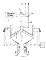
廃棄物溶融炉には、被処理物を溶融処理する主室1内で燃料を燃焼させて燃焼火炎を形成する燃焼装置5を備え、前記主室1内の温度を検出するシース型熱伝対を用いた温度検出手段2を設けてある。そして、前記燃焼装置5には、燃料を供給する燃料供給路6と、前記燃料を燃焼させるための空気を供給する空気供給路7とを備えている。前記燃料供給路6には前記燃焼装置5への燃料供給量を調節する燃料調節弁6aを備え、前記空気供給路7には前記燃焼装置5への空気供給量を調節する空気調節弁7aを備えている。さらに、前記温度検出手段2で検出した主室内温度と前記主室1の目標温度とに基づき開度調節するための、演算手段4を備える燃焼制御手段3を設けてある。
【0018】
前記演算手段4は、主室温度(TF ) と、前記主室1からの排ガスの定圧比熱(Cpe)と、前記排ガスの流量(Ge)と、前記主室1に供給する燃料の低位発熱量(Hu)と、前記主室1に供給する燃料の温度(Tf)と、前記燃料の定圧比熱(Cpf)と、燃料の追加に伴い前記燃焼装置5、即ち前記主室1に供給される空気の定圧比熱(Cpa)と、前記空気の温度(Ta)と、前記燃料追加量に対する理論空気量係数(α)と、前記主室1における燃料に対する所定空気比(λ)とに基づき、前記主室1内を前記目標温度(TT ) に維持するに必要とする燃料追加量(Gf)を、計算式
Gf =Cpe×Ge × (TT −TF ) /{Hu +Cpf×(Tf −TT ) +Cpa×α×λ×(Ta −TT )}
により計算するように構成してある。
【0019】
前記燃焼制御手段3は、前記演算手段4で算出した燃料追加量(Gf)を前記燃焼装置5に加給するように前記燃料供給路6に備える燃料調節弁6aの開度を調節するとともに、前記燃料調節弁6aの開度調節に伴い、前記主室1内を所定の空気比に維持すべく前記空気供給路7に備える空気調節弁7aの開度を調節するように構成してある。
【0020】
以上のように構成してあるから、前記廃棄物溶融炉における各プロセスデータ(Cpe, Ge,TF , Hu,Cpf, Tf,Cpa, α, λ, Ta )から一意的に前記主室1内を所定の目標温度(TT ) に維持するための燃料追加量(Gf)を算出でき、その結果に基づいて前記燃焼装置5に供給する燃料及び空気の量を調節するから、従来のフィードバック制御と異なり、制御のハンティング(即ちオーバーシュート、アンダーシュート)を防止できる。
【0021】
次に、本発明の他の実施の形態について説明する。
〈1〉上記実施の形態に於いては、演算手段4が、主室温度(TF ) と、前記主室1からの排ガスの定圧比熱(Cpe)と、前記排ガスの流量(Ge)と、前記主室1に供給する燃料の低位発熱量(Hu)と、前記主室1に供給する燃料の温度(Tf)と、前記燃料の定圧比熱(Cpf)と、燃料の追加に伴い前記燃焼装置5、即ち前記主室1に供給される空気の定圧比熱(Cpa)と、前記空気の温度(Ta)と、前記燃料追加量に対する理論空気量係数(α)と、前記主室1における燃料に対する所定空気比(λ)とに基づき、前記主室1内を前記目標温度(TT ) に維持するに必要とする燃料追加量(Gf)を、計算式
Gf =Cpe×Ge × (TT −TF ) /{Hu +Cpf×(Tf −TT ) +Cpa×α×λ×(Ta −TT )}
により計算するように構成してある例について説明したが、前記燃料追加量(Gf)を求めるのに、前記主室温度(TF ) を前記目標温度(TT ) に維持するに必要とする所要熱量(ΔQ)を、前記排ガスの定圧比熱(Cpe)と、前記排ガスの流量(Ge)と、前記目標温度(TT ) と前記主室温度(TF ) との差とから、計算式
ΔQ=Cpe×Ge ×(TT −TF )
により算出し、算出した所要熱量(ΔQ)と、前記主室1に供給する燃料の低位発熱量(Hu)とから、前記燃料追加量(Gf)を、計算式
Gf =ΔQ/Hu
により求めるように構成してあってもよい。このように構成すれば、簡単な計算でありながら、比較的精度よく制御できる。
〈2〉上記実施の形態に於いては、演算手段4が、主室温度(TF ) と、前記主室1からの排ガスの定圧比熱(Cpe)と、前記排ガスの流量(Ge)と、前記主室1に供給する燃料の低位発熱量(Hu)と、前記主室1に供給する燃料の温度(Tf)と、前記燃料の定圧比熱(Cpf)と、燃料の追加に伴い前記燃焼装置5、即ち前記主室1に供給される空気の定圧比熱(Cpa)と、前記空気の温度(Ta)と、前記燃料追加量に対する理論空気量係数(α)と、前記主室1における燃料に対する所定空気比(λ)とに基づき、前記主室1内を前記目標温度(TT ) に維持するに必要とする燃料追加量(Gf)を、計算式
Gf =Cpe×Ge × (TT −TF ) /{Hu +Cpf×(Tf −TT ) +Cpa×α×λ×(Ta −TT )}
により計算するように構成してある例について説明したが、前記燃料追加量(Gf)を求めて制御するのに代えて、前記主室温度(TF ) を、前記目標温度(TT ) に維持するに必要とする熱量(ΔQT ) を、前記排ガスの定圧比熱(Cpe)と、前記排ガスの流量(Ge)と、前記目標温度(TT ) と大気温度(Ta)との差とから、計算式
ΔQT =Cpe×Ge ×(TT −Ta)
により算出し、前記算出した必要熱量(ΔQT ) に対して、前記主室1に供給する燃料の低位発熱量(Hu)に基づき、前記燃焼装置5に燃料を供給する目標燃料供給量(GfT)を、計算式
GfT=ΔQT /Hu
により求めて前記燃焼装置5への目標燃料供給量(GfT)を設定するように構成してあってもよい。
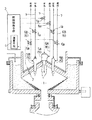
〈3〉上記実施の形態に於いては、単一の前記燃焼装置5に単一の燃料を供給する例について説明したが、前記燃焼装置5への燃料供給路6を、例えば図2に示すように、燃焼装置5Aへの燃料供給路6Aと、燃焼装置5Bへの燃料供給路6Bに分割形成して、複数の燃料供給経路を設け、異なる種類の燃料を同時に供給可能に構成すると共に、前記燃料追加量(Gf)を求めるのに、夫々の燃料の低位発熱量(Hu1),( Hu2)とその各々の流量(Gf1),( Gf2)及び定圧比熱(Cpf1),(Cpf2)に対して、前記空気供給量を前記夫々の燃料に対して算出するように構成した、前記主室温度(TF ) と、前記主室1からの排ガスの流量(Ge)と、前記主室1内を前記目標温度(TT ) に維持するに必要な夫々の燃料に関する燃料追加量(Gf1),( Gf2) と、夫々の燃料追加量に対する理論空気量係数(α1),(α2)と、前記主室1内の所定空気比(λ)と、供給空気温度(Ta)とに基づき、前記目標温度(TT ) に対する前記主室温度(TF ) の温度偏差に相当する所要熱量(ΔQ1)を算出する計算式
ΔQ1 =Cpe×Ge × (TT −TF ) +Cpa×(Gf1×α1 +Gf2×α2 )×λ×(TT −Ta)+{Cpf1 ×Gf1×(TT −Tf1) +Cpf2 ×Gf2×(TT −Tf2 )}
と、前記夫々の燃料追加量(Gf1),( Gf2) と、これに対して前記所定空気比(λ)で供給する空気量とによる前記主室1内への夫々の燃料の供給に伴う供給熱量(ΔQ21),(ΔQ22)を算出する計算式
ΔQ21=Gf1×Hu1
ΔQ22=Gf2×Hu2
とに対して、前記燃料追加量(Gf1),( Gf2) をパラメータとして、逐次前記所要熱量(ΔQ1)と前記供給熱量の和(ΔQ21+ΔQ22)を計算し、前記所要熱量(ΔQ1)と前記供給熱量の和(ΔQ21+ΔQ22)との差が所定の収束値以下となるまで計算を繰り返して収束計算を行い燃料追加量(Gf)を算出するようにしてあってもよい。尚、説明の簡単のために上記は二種類の燃料を供給する例について説明したが、三種類以上の燃料を供給するようにしてあってもよい。
【0022】
尚、特許請求の範囲の項に図面との対照を便利にするために符号を記すが、該記入により本発明は添付図面の構成に限定されるものではない。
【図面の簡単な説明】
【図1】本発明に係る廃棄物溶融炉の一例の説明図
【図2】本発明に係る廃棄物溶融炉の他の例の説明図
【符号の説明】
1 主室
2 温度検出手段
3 燃焼制御手段
4 演算手段
5 燃焼装置
6 燃料供給路
6a 燃料調節弁
7a 空気調節弁[0001]
TECHNICAL FIELD OF THE INVENTION
The present invention relates to a control device and a combustion control method for a waste melting furnace, and more particularly to a control device and a combustion control method, which include a combustion device that forms a combustion flame by burning fuel in a main chamber that melts and processes an object to be processed, A temperature control means for adjusting the amount of fuel supplied to the combustion device, and an air control valve for adjusting the amount of air supplied to the combustion device, wherein the temperature detection means detects the temperature. The present invention relates to a combustion control device of a waste melting furnace having a combustion control means for adjusting an opening degree based on a room temperature and a target temperature of the main chamber, and a combustion control method therefor.
[0002]
[Prior art]
Conventionally, in a waste melting furnace, a temperature detecting means for detecting an exhaust gas temperature is provided at an exhaust gas outlet from a main chamber for melting and processing an inputted object to be treated, and the temperature in the furnace is determined based on the detected temperature from the temperature detecting means. Is detected, and the fuel supply amount is adjusted so that the detected furnace temperature approaches the target temperature (for example, see Japanese Patent Publication No. 4-35676).
[0003]
[Problems to be solved by the invention]
In the combustion control of the above-mentioned conventional waste melting furnace, feedback control is performed, and hunting, overshoot, and undershoot are inevitable. To reduce the degree, control with a large delay is performed at the expense of response speed. There was a compelling problem. In addition, when overshooting is allowed with an emphasis on the response speed, extra fuel is required, which is not preferable from the viewpoint of saving fuel resources.
Therefore, an object of the present invention is to provide a means for preventing combustion hunting while supplying an appropriate amount of fuel while solving the above-mentioned problems. And
[0004]
[Means for Solving the Problems]
(Feature configuration)
A first characteristic configuration of the combustion control apparatus of the waste melting furnace according to the present invention for the above-mentioned object is, as described in
(However, Delta] Q: heating requirements calculated, Cpe: exhaust gas specific heat at constant pressure, Ge: exhaust gas flow rate from the main chamber, T T: target temperature of the main chamber, T F: main compartment temperature) by the main to the target temperature Calculate the required heat amount corresponding to the temperature deviation of the room temperature, based on the calculated required heat amount, based on the lower heating value of the fuel,
Gf = ΔQ / Hu
(Where, Gf: additional fuel amount, Hu: lower heating value of fuel), an arithmetic means for calculating the additional fuel amount is provided in the combustion control means, and the combustion control means is replaced by the additional fuel amount calculated by the arithmetic means. In addition to adjusting the opening of the fuel control valve so as to increase the pressure, the opening of the air control valve is adjusted to maintain a predetermined air ratio with the adjustment of the opening of the fuel control valve. On the point. The additional fuel amount includes a negative value, and the addition of the negative additional fuel amount means a decrease in the fuel supply amount. In this regard, the same applies hereinafter.
[0005]
A second characteristic configuration of the combustion control apparatus of the waste melting furnace according to the present invention for the above object is as described in
(However, Gf: fuel addition amount, Cpe: exhaust gas specific heat at constant pressure, Ge: exhaust gas flow rate from the main chamber, T T: target temperature of the main chamber, T F: main compartment temperature, Hu: lower heating value of the fuel, Cpf : Constant-pressure specific heat of fuel, Tf: temperature of supplied fuel, Cpa: constant-pressure specific heat of air, α: theoretical air amount coefficient for added fuel amount, λ: predetermined air ratio, Ta: supply air temperature). Arithmetic means for calculating an additional amount of fuel required to maintain the temperature is provided in the combustion control means, and the combustion control means adjusts the opening of the fuel control valve so as to add the additional amount of fuel calculated by the arithmetic means. In addition to adjusting the opening degree of the fuel control valve, the opening degree of the air control valve is adjusted so as to maintain the main chamber at a predetermined air ratio.
[0006]
A third characteristic configuration of the combustion control apparatus of the waste melting furnace according to the present invention for the above-mentioned object is as described in
(However, .DELTA.Q1: heating requirements calculated, Cpe: exhaust gas specific heat at constant pressure, Ge: exhaust gas flow rate from the main chamber, T T: target temperature of the main chamber, T F: main compartment temperature, Cpa: air specific heat at constant pressure, Gf: additional fuel amount, α: theoretical air amount coefficient to additional fuel amount, λ: predetermined air ratio, Ta: supply air temperature, Cpf: constant pressure specific heat of fuel, Tf: supply fuel temperature), and the additional fuel amount. A formula ΔQ2 = Gf × Hu for calculating the amount of heat supplied to the main chamber based on the amount of air supplied at a predetermined air ratio.
(Where Hu is the lower heating value of the fuel), and the convergence calculation for setting the difference between the required heat amount and the supplied heat amount to be equal to or less than a predetermined convergence value by using the additional fuel amount as a parameter for both equations. The combustion control means is provided with a calculation means for calculating the fuel addition amount, and the combustion control means adjusts the opening degree of the fuel control valve so as to supply the fuel addition amount calculated by the calculation means, and The point is that the opening degree of the air control valve is adjusted in accordance with the opening degree adjustment of the control valve so as to maintain the main chamber at a predetermined air ratio. Note that setting the difference to a predetermined convergence value or less means that the absolute value of the convergence value is determined and the absolute value of the difference is equal to or less than the absolute value of the convergence value. In this regard, the same applies hereinafter.
[0007]
According to a fourth aspect of the present invention, a plurality of fuel supply paths to the combustion device according to the third characteristic configuration are provided so as to be able to simultaneously supply different types of fuel, and the arithmetic means is configured to operate the plurality of fuel supply paths. For the passages, the fuel supply means is configured to supply an additional amount of fuel to each fuel, and the fuel control means is configured to supply the additional fuel amount to each of the fuels calculated by the arithmetic means to the plurality of fuel supply paths. If the configuration is such that the opening of the fuel control valve provided is individually adjusted and the opening of the air control valve is adjusted in accordance with the adjustment of the opening of each fuel control valve (fourth characteristic configuration). Even better. In the case where air is supplied for each fuel in the combustion device, an air amount control valve may be provided in each air supply passage to adjust each air supply amount so as to adjust each air ratio. When the fuel and the air are mixed and post-combusted in the main chamber while the fuel is supplied from the supply passage into the main chamber, the air supply is determined by determining the air ratio based on the theoretical air amount for each fuel. The amount can be set.
[0008]
A first characteristic configuration of the combustion control method of the waste melting furnace according to the present invention for the above object is, as described in
(However, Delta] Q: heating requirements calculated, Cpe: exhaust gas specific heat at constant pressure, Ge: exhaust gas flow rate from the main chamber, T T: target temperature of the main chamber, T F: main compartment temperature) by the main to the target temperature Calculate the required heat amount corresponding to the temperature deviation of the room temperature, based on the calculated required heat amount, based on the lower heating value of the fuel,
Gf = ΔQ / Hu
(However, Gf: additional fuel amount, Hu: lower heating value of fuel), the additional fuel amount is calculated, and the calculated additional fuel amount is added to the fuel supply amount to the combustion device. The point is that the air supply amount is adjusted to maintain a predetermined air ratio with respect to the fuel supply amount.
[0009]
A second characteristic configuration of the combustion control method of the waste melting furnace according to the present invention for the above purpose is as described in
(However, Gf: fuel addition amount, Cpe: exhaust gas specific heat at constant pressure, Ge: exhaust gas flow rate from the main chamber, T T: target temperature of the main chamber, T F: main compartment temperature, Hu: lower heating value of the fuel, Cpf : Constant-pressure specific heat of fuel, Tf: temperature of supplied fuel, Cpa: constant-pressure specific heat of air, α: theoretical air amount coefficient to added fuel amount, λ: predetermined air ratio, Ta: supply air temperature) Calculate the amount of additional fuel necessary to maintain the fuel supply amount, and add the calculated additional amount of fuel to the amount of fuel supplied to the combustion device, and maintain a predetermined air ratio with respect to the amount of fuel supply after the addition. The point is to adjust the air supply amount in order to achieve this.
[0010]
A third characteristic configuration of the method for controlling combustion of a waste melting furnace according to the present invention for the above object is as described in
(However, .DELTA.Q1: heating requirements calculated, Cpe: exhaust gas specific heat at constant pressure, Ge: exhaust gas flow rate from the main chamber, T T: target temperature of the main chamber, T F: main compartment temperature, Cpa: air specific heat at constant pressure, Gf: additional fuel amount, α: theoretical air amount coefficient with respect to additional fuel amount, λ: predetermined air ratio, Ta: supply air temperature, Cpf: constant pressure specific heat of fuel, Tf: supply fuel temperature)
ΔQ2 = Gf × Hu for calculating the amount of heat supplied to the main chamber based on the amount of fuel added and the amount of air supplied at a predetermined air ratio.
(Where Hu is the lower heating value of the fuel), and a convergence calculation for converging the difference between the required heat amount and the supplied heat amount to a predetermined convergence value or less using the additional fuel as a parameter for both equations. The fuel addition amount is calculated, and the calculated fuel addition amount is added to the fuel supply amount to the combustion device, and the air supply amount is maintained to maintain a predetermined air ratio with respect to the fuel supply amount after the addition. The point is to adjust the amount.
[0011]
As described in claim 8, a plurality of different types of fuel are supplied to the combustion device in the third characteristic configuration of the combustion control method, and a fuel addition amount is separately calculated for the plurality of fuels. Adding the calculated fuel addition amount to each fuel supply amount to the combustion device, and maintaining the air supply amount at a predetermined air ratio for each fuel supply amount after the addition. (4th characteristic configuration) is even better.
[0012]
[Effects of each feature configuration]
According to the first characteristic configuration of the combustion control device of the waste melting furnace or the first characteristic configuration of the combustion control method, the main chamber temperature can be maintained at the target temperature while preventing excessive supply of fuel. In other words, the required amount of heat in the furnace is calculated, and the required amount of additional fuel is calculated, so that the minimum required fuel supply amount can be set, and the overshoot can be avoided by performing the prediction control. Therefore, excessive supply of fuel can be prevented. As a result, hunting of combustion control can be prevented while maintaining an appropriate amount of fuel supply.
[0013]
According to the second characteristic configuration of the combustion control device of the waste melting furnace or the second characteristic configuration of the combustion control method, hunting of the combustion control can be prevented while increasing the response speed of the control. In other words, since the additional amount of fuel and the additional amount of air obtained as an analytical solution obtained from the formula for calculating the required heating amount and the formula for obtaining the replenishing heat amount are supplied, it is necessary to supply the minimum necessary and sufficient heat amount. Thus, it is possible to prevent the supply of excess heat while maintaining the main room temperature at the target temperature.
As a result, hunting of combustion control can be prevented while supplying an appropriate amount of fuel.
[0014]
According to the third characteristic configuration of the combustion control device of the waste melting furnace or the third characteristic configuration of the combustion control method, hunting of the combustion control can be prevented while increasing the response speed of the control. In other words, the formula for giving the required heating amount and the formula for giving the replenishing heat amount can be arbitrarily determined by the calculation formula, and therefore, can be set by the conditional formula according to the conditions of the apparatus. For example, a convergence solution can be easily obtained by convergence calculation even under a condition in which it is not easy to find a solution due to a large number of unknowns when finding an analytical solution. In particular, a solution can be easily obtained even when a plurality of types of fuels are burned in a furnace. In addition, a minimum necessary and sufficient amount of heat is supplied, so that an excessive amount of heat can be prevented while maintaining the main room temperature at the target temperature.
As a result, even when a plurality of types of fuel are supplied, hunting of combustion control can be prevented while supplying an appropriate amount of fuel.
[0015]
According to the fourth characteristic configuration of the combustion control device of the waste melting furnace or the fourth characteristic configuration of the combustion control method, in addition to the operation and effect of the third characteristic configuration, an appropriate amount of fuel can be supplied even under the supply of a plurality of fuels. The fuel addition amount can be set, and the hunting of the combustion control can be prevented while increasing the response speed of the control. In other words, using a calculation formula for calculating the replenishable heat quantity that can be supplied for each of the plurality of fuels and a calculation formula for calculating the required heat quantity for each of the additional fuel quantities for the plurality of fuels, the fuel addition quantity that is the solution is calculated for each fuel. Is obtained, the additional amount of each fuel is the minimum necessary and sufficient supply amount, and therefore, there is no excess heat supply, so that control overshoot can be prevented. Undershoot can be prevented. For example, when two types of fuels are to be burned, it is possible to arbitrarily determine an additional amount of both fuels without determining the supply ratio of the two fuels, and the form of air supply is also variously variable. is there. In the case of supplying more types of fuels, for example, if the repetition conditions are set so as to preferentially add a fuel having a high combustion calorific value, the control response can be improved, and the combustion should be preferentially performed. If the repetitive conditions are set so as to increase the supply amount of fuel, the additional supply amount of each fuel can be determined according to the conditions.
As a result, while supplying a plurality of types of fuel, the fuel addition amount can be maintained at an appropriate amount, and hunting of combustion control can be prevented.
[0016]
BEST MODE FOR CARRYING OUT THE INVENTION
An example of an embodiment of the combustion control apparatus for a waste melting furnace of the present invention will be described below with reference to the drawings.
[0017]
The waste melting furnace includes a
[0018]
The calculating means 4 calculates a main chamber temperature ( TF ), a constant pressure specific heat (Cpe) of the exhaust gas from the
It is configured to calculate by
[0019]
The combustion control means 3 adjusts an opening degree of a
[0020]
With the above configuration, the
[0021]
Next, another embodiment of the present invention will be described.
<1> In the above embodiment, the calculating means 4 calculates the main chamber temperature ( TF ), the constant pressure specific heat of the exhaust gas from the main chamber 1 (Cpe), the flow rate of the exhaust gas (Ge), The lower heating value (Hu) of the fuel to be supplied to the
Has been described, it is necessary to maintain the main chamber temperature (T F ) at the target temperature (T T ) to obtain the fuel addition amount (Gf). The required heat quantity (ΔQ) is calculated from a constant pressure specific heat (Cpe) of the exhaust gas, a flow rate (Ge) of the exhaust gas, and a difference between the target temperature (T T ) and the main chamber temperature (T F ). ΔQ = Cpe × Ge × (T T -T F)
From the required calorific value (ΔQ) and the lower calorific value (Hu) of the fuel supplied to the
May be configured to be obtained by With such a configuration, it is possible to control with relatively high accuracy while performing simple calculations.
<2> In the above embodiment, the calculating means 4 calculates the main chamber temperature ( TF ), the constant pressure specific heat of the exhaust gas from the main chamber 1 (Cpe), the flow rate of the exhaust gas (Ge), The lower heating value (Hu) of the fuel to be supplied to the
Has been described, the main chamber temperature (T F ) is changed to the target temperature (T T ) instead of calculating and controlling the additional fuel amount (Gf). The amount of heat (ΔQ T ) required for maintenance is determined from the constant pressure specific heat (Cpe) of the exhaust gas, the flow rate (Ge) of the exhaust gas, and the difference between the target temperature (T T ) and the atmospheric temperature (Ta). , Calculation formula ΔQ T = Cpe × Ge × (T T −Ta)
And a target fuel supply amount (Gf) for supplying fuel to the
And the target fuel supply amount (Gf T ) to the
<3> In the above-described embodiment, an example in which a single fuel is supplied to the
And the respective fuel addition amounts (Gf 1 ) and (Gf 2 ) and the amount of air supplied at the predetermined air ratio (λ) with respect to the supply of the respective fuels into the
ΔQ2 2 = Gf 2 × Hu 2
, The sum of the required heat quantity (ΔQ1) and the supplied heat quantity (ΔQ2 1 + ΔQ2 2 ) is sequentially calculated using the additional fuel quantities (Gf 1 ) and (Gf 2 ) as parameters, and the required heat quantity (ΔQ1 ) And the sum of the supplied heat amounts (ΔQ2 1 + ΔQ2 2 ) may be repeated until the difference becomes equal to or less than a predetermined convergence value to perform the convergence calculation to calculate the fuel addition amount (Gf). In addition, for the sake of simplicity, the example in which two types of fuel are supplied has been described above, but three or more types of fuel may be supplied.
[0022]
Incidentally, reference numerals are written in the claims for convenience of comparison with the drawings, but the present invention is not limited to the configuration of the attached drawings by the entry.
[Brief description of the drawings]
FIG. 1 is an explanatory view of an example of a waste melting furnace according to the present invention. FIG. 2 is an explanatory view of another example of a waste melting furnace according to the present invention.
DESCRIPTION OF
Claims (8)
ΔQ=Cpe×Ge×(TT−TF)
(但し、ΔQ:算出される所要熱量、Cpe:排ガスの定圧比熱、Ge:主室からの排ガス流量、TT:主室の目標温度、TF:主室温度)
により、前記目標温度に対する前記主室温度の温度偏差に相当する所要熱量を算出し、前記算出した所要熱量に対して、燃料の低位発熱量に基づき、
Gf =ΔQ/Hu
(但し、Gf:燃料追加量、Hu:燃料の低位発熱量)
として、燃料追加量を算出する演算手段(4)を前記燃焼制御手段(3)に設けて、前記燃焼制御手段(3)を、前記演算手段(4)で算出した燃料追加量を加給するように前記燃料調節弁(6a)の開度を調節するとともに、前記燃料調節弁(6a)の開度調節に伴い、所定の空気比に維持すべく前記空気調節弁(7a)の開度を調節するように構成してある廃棄物溶融炉の燃焼制御装置。In a waste melting furnace provided with a combustion device (5) for burning a fuel in a main chamber (1) for melting and processing an object to be processed to form a combustion flame, a temperature for detecting a temperature in the main chamber (1). A fuel control valve (6a) provided with a detecting means (2) for adjusting a fuel supply amount to the combustion device (5); and an air control valve (7a) for adjusting an air supply amount to the combustion device (5) ), A combustion control device for a waste melting furnace, comprising combustion control means (3) for adjusting the opening based on the main room temperature detected by the temperature detection means (2) and the target temperature of the main chamber (1). a is, with the main chamber temperature, based on the exhaust gas flow from the main chamber (1), equation ΔQ = Cpe × Ge × (T T -T F)
(However, ΔQ: required calorie to be calculated, Cpe: constant heat of exhaust gas at a constant pressure, Ge: exhaust gas flow rate from the main chamber, T T : target temperature of the main chamber, TF : main chamber temperature)
By calculating the required heat amount corresponding to the temperature deviation of the main chamber temperature with respect to the target temperature, based on the calculated required heat amount, based on the lower heating value of the fuel,
Gf = ΔQ / Hu
(However, Gf: additional amount of fuel, Hu: lower heating value of fuel)
In the combustion control means (3), a calculation means (4) for calculating an additional fuel amount is provided so that the combustion control means (3) adds the fuel addition amount calculated by the calculation means (4). In addition to adjusting the opening of the fuel control valve (6a), the opening of the air control valve (7a) is adjusted to maintain a predetermined air ratio with the adjustment of the opening of the fuel control valve (6a). A combustion control device for a waste melting furnace configured to perform
Gf=Cpe×Ge×(TT−TF)/{Hu+Cpf×(Tf−TT)+Cpa×α×λ×(T a −T T )}
(但し、Gf:燃料追加量、Cpe:排ガスの定圧比熱、Ge:主室からの排ガス流量、TT:主室の目標温度、TF:主室温度、Hu:燃料の低位発熱量、Cpf:燃料の定圧比熱、Tf:供給燃料の温度、Cpa:空気の定圧比熱、α:燃料追加量に対する理論空気量係数、λ:所定空気比、Ta:供給空気温度)
により、前記主室(1)内を前記目標温度に維持するに必要な燃料追加量を算出する演算手段(4)を前記燃焼制御手段(3)に設けて、前記燃焼制御手段(3)を、前記演算手段(4)で算出した燃料追加量を加給するように前記燃料調節弁(6a)の開度を調節するとともに、前記燃料調節弁(6a)の開度調節に伴い、前記主室(1)内を所定の空気比に維持すべく前記空気調節弁(7a)の開度を調節するように構成してある廃棄物溶融炉の燃焼制御装置。In a waste melting furnace provided with a combustion device (5) for burning a fuel in a main chamber (1) for melting and processing an object to be processed to form a combustion flame, a temperature for detecting a temperature in the main chamber (1). A fuel control valve (6a) provided with a detecting means (2) for adjusting a fuel supply amount to the combustion device (5); and an air control valve (7a) for adjusting an air supply amount to the combustion device (5) ), A combustion control device for a waste melting furnace, comprising combustion control means (3) for adjusting the opening based on the main room temperature detected by the temperature detection means (2) and the target temperature of the main chamber (1). A calculation formula Gf = Cpe × Ge based on the temperature of the main chamber, the flow rate of exhaust gas from the main chamber (1), the lower heating value of the fuel, the temperature of the supplied fuel, and the temperature of the supplied air. × (T T -T F) / {Hu + Cpf × (Tf-T T) + Cpa × α × λ × (T a -T T)}
(However, Gf: fuel addition amount, Cpe: exhaust gas specific heat at constant pressure, Ge: exhaust gas flow rate from the main chamber, T T: target temperature of the main chamber, T F: main compartment temperature, Hu: lower heating value of the fuel, Cpf : Constant pressure specific heat of fuel, Tf: temperature of supplied fuel, Cpa: constant pressure specific heat of air, α: theoretical air amount coefficient to added fuel amount, λ: predetermined air ratio, Ta: supply air temperature)
Thus, the combustion control means (3) is provided with a calculation means (4) for calculating an additional amount of fuel required to maintain the inside of the main chamber (1) at the target temperature, and the combustion control means (3) is provided. The opening of the fuel control valve (6a) is adjusted so as to supply the additional amount of fuel calculated by the calculating means (4), and the opening of the fuel control valve (6a) is adjusted. (1) A combustion control device for a waste melting furnace configured to adjust the opening of the air control valve (7a) so as to maintain the inside at a predetermined air ratio.
ΔQ1=Cpe×Ge×(TT−TF)+Cpa×Gf×α×λ×(TT−Ta)+Cpf×Gf×(T T −T f)
(但し、ΔQ1:算出される所要熱量、Cpe:排ガスの定圧比熱、Ge:主室からの排ガス流量、TT:主室の目標温度、TF:主室温度、Cpa:空気の定圧比熱、Gf:燃料追加量、α:燃料追加量に対する理論空気量係数、λ:所定空気比、Ta:供給空気温度、Cpf:燃料の定圧比熱、Tf:供給燃料の温度)
と、前記燃料追加量と、これに対して所定空気比で供給する空気量とによる前記主室(1)内への供給熱量を算出する計算式
ΔQ2=Gf×Hu
(但し、ΔQ2:算出される供給熱量、Hu:燃料の低位発熱量)
とに基づき、前記両式に対して前記追加燃料をパラメータとして、前記所要熱量と前記供給熱量との差を所定の収束値以下とする収束計算を行い燃料追加量を算出する演算手段(4)を前記燃焼制御手段(3)に設けて、前記燃焼制御手段(3)を、前記演算手段(4)で算出した燃料追加量を加給するように前記燃料調節弁(6a)の開度を調節するとともに、前記燃料調節弁(6a)の開度調節に伴い、前記主室(1)内を所定の空気比に維持すべく前記空気調節弁(7a)の開度を調節するように構成してある廃棄物溶融炉の燃焼制御装置。In a waste melting furnace provided with a combustion device (5) for burning a fuel in a main chamber (1) for melting and processing an object to be processed to form a combustion flame, a temperature for detecting a temperature in the main chamber (1). A fuel control valve (6a) provided with a detecting means (2) for adjusting a fuel supply amount to the combustion device (5); and an air control valve (7a) for adjusting an air supply amount to the combustion device (5) ), A combustion control device for a waste melting furnace, comprising combustion control means (3) for adjusting the opening based on the main room temperature detected by the temperature detection means (2) and the target temperature of the main chamber (1). The target temperature based on the main chamber temperature, the flow rate of exhaust gas from the main chamber (1), and an additional amount of fuel required to maintain the inside of the main chamber (1) at the target temperature. Formula ΔQ1 = Cpe × G for calculating the required heat quantity corresponding to the temperature deviation of the main chamber temperature with respect to e × (T T -T F) + Cpa × Gf × α × λ × (T T -Ta) + Cpf × Gf × (T T -T f)
(However, .DELTA.Q1: heating requirements calculated, Cpe: exhaust gas specific heat at constant pressure, Ge: exhaust gas flow rate from the main chamber, T T: target temperature of the main chamber, T F: main compartment temperature, Cpa: air specific heat at constant pressure, Gf: additional fuel amount, α: theoretical air amount coefficient with respect to additional fuel amount, λ: predetermined air ratio, Ta: supply air temperature, Cpf: constant pressure specific heat of fuel, Tf: supply fuel temperature)
ΔQ2 = Gf × Hu for calculating the amount of heat supplied to the main chamber (1) based on the amount of fuel added and the amount of air supplied at a predetermined air ratio.
(However, ΔQ2: calorific value of supply heat, Hu: lower calorific value of fuel)
Computing means (4) for performing a convergence calculation to make a difference between the required heat amount and the supplied heat amount equal to or less than a predetermined convergence value by using the additional fuel as a parameter with respect to both of the above formulas. Is provided in the combustion control means (3), and the opening degree of the fuel control valve (6a) is adjusted so that the combustion control means (3) supplies the additional fuel amount calculated by the calculation means (4). In addition, with the adjustment of the opening degree of the fuel adjustment valve (6a), the opening degree of the air adjustment valve (7a) is adjusted to maintain the inside of the main chamber (1) at a predetermined air ratio. Control system for waste melting furnace.
ΔQ=Cpe×Ge×(TT−TF)
(但し、ΔQ:算出される所要熱量、Cpe:排ガスの定圧比熱、Ge:主室からの排ガス流量、TT:主室の目標温度、TF:主室温度)
により、前記目標温度に対する前記主室温度の温度偏差に相当する所要熱量を算出し、前記算出した所要熱量に対して、燃料の低位発熱量に基づき、
Gf=ΔQ/Hu
(但し、Gf:燃料追加量、Hu:燃料の低位発熱量)
として、燃料追加量を算出して、前記燃焼装置(5)への燃料供給量に、前記算出した燃料追加量を加給するとともに、前記加給後の燃料供給量に対して、所定の空気比に維持すべく前記空気供給量を調節する廃棄物溶融炉の燃焼制御方法。A temperature for detecting a temperature in the main chamber (1) in a waste melting furnace provided with a combustion device (5) for burning a fuel in a main chamber (1) for melting and processing an object to be processed to form a combustion flame. A detecting means (2) is provided, and a fuel supply amount and an air supply amount to the combustion device (5) are detected by the temperature detecting means (2) in a main chamber temperature and a target temperature of the main chamber (1). And controlling the combustion of the waste melting furnace based on the following formula: ΔQ = Cpe × Ge × (T T −) based on the temperature of the main chamber and the flow rate of exhaust gas from the main chamber (1). TF )
(However, ΔQ: required calorie to be calculated, Cpe: constant heat of exhaust gas at a constant pressure, Ge: exhaust gas flow rate from the main chamber, T T : target temperature of the main chamber, TF : main chamber temperature)
By calculating the required heat amount corresponding to the temperature deviation of the main chamber temperature with respect to the target temperature, based on the calculated required heat amount, based on the lower heating value of the fuel,
Gf = ΔQ / Hu
(However, Gf: additional amount of fuel, Hu: lower heating value of fuel)
The fuel addition amount is calculated, and the calculated fuel addition amount is added to the fuel supply amount to the combustion device (5), and a predetermined air ratio is set to the fuel supply amount after the addition. A combustion control method for a waste melting furnace, wherein the air supply amount is adjusted to maintain the air supply amount.
Gf=Cpe×Ge×(TT−TF)/{Hu+Cpf×(Tf−TT)+Cpa×α×λ×(Ta−TT)}
(但し、Gf:燃料追加量、Cpe:排ガスの定圧比熱、Ge:主室からの排ガス流量、TT:主室の目標温度、TF:主室温度、Hu:燃料の低位発熱量、Cpf:燃料の定圧比熱、Tf:供給燃料の温度、Cpa:空気の定圧比熱、α:燃料追加量に対する理論空気量係数、λ:所定空気比、Ta:供給空気温度)
により、前記主室(1)内を前記目標温度に維持するに必要な燃料追加量を算出して、前記燃焼装置(5)への燃料供給量に、前記算出した燃料追加量を加給するとともに、前記加給後の燃料供給量に対して、所定の空気比に維持すべく前記空気供給量を調節する廃棄物溶融炉の燃焼制御方法。A temperature for detecting a temperature in the main chamber (1) in a waste melting furnace provided with a combustion device (5) for burning a fuel in a main chamber (1) for melting and processing an object to be processed to form a combustion flame. A detecting means (2) is provided, and a fuel supply amount and an air supply amount to the combustion device (5) are detected by the temperature detecting means (2) in a main chamber temperature and a target temperature of the main chamber (1). A combustion control method for a waste melting furnace, wherein the temperature of the main chamber, the flow rate of exhaust gas from the main chamber (1), the lower heating value of the fuel, the temperature of the supplied fuel, based on the air temperature, formula Gf = Cpe × Ge × (T T -T F) / {Hu + Cpf × (Tf-T T) + Cpa × α × λ × (Ta-T T)}
(However, Gf: fuel addition amount, Cpe: exhaust gas specific heat at constant pressure, Ge: exhaust gas flow rate from the main chamber, T T: target temperature of the main chamber, T F: main compartment temperature, Hu: lower heating value of the fuel, Cpf : Constant pressure specific heat of fuel, Tf: temperature of supplied fuel, Cpa: constant pressure specific heat of air, α: theoretical air amount coefficient to added fuel amount, λ: predetermined air ratio, Ta: supply air temperature)
By calculating the amount of additional fuel required to maintain the inside of the main chamber (1) at the target temperature, the calculated amount of additional fuel is added to the amount of fuel supplied to the combustion device (5). A combustion control method for a waste melting furnace, wherein the air supply amount is adjusted to maintain a predetermined air ratio with respect to the fuel supply amount after the supply.
ΔQ1=Cpe×Ge×(TT−TF)+Cpa×Gf×α×λ×(TT−Ta)+Cpf×Gf×(T T −T f)
(但し、ΔQ1:算出される所要熱量、Cpe:排ガスの定圧比熱、Ge:主室からの排ガス流量、TT:主室の目標温度、TF:主室温度、Cpa:空気の定圧比熱、Gf:燃料追加量、α:燃料追加量に対する理論空気量係数、λ:所定空気比、Ta:供給空気温度、Cpf:燃料の定圧比熱、Tf:供給燃料の温度)
と、前記燃料追加量と、これに対して所定空気比で供給する空気量とによる前記主室(1)内への供給熱量を算出する計算式
ΔQ2=Gf×Hu
(但し、Hu:燃料の低位発熱量)
とに基づき、前記両式に対して前記追加燃料をパラメータとして、前記所要熱量と前記供給熱量との差を所定の収束値以下に収束させる収束計算を行い燃料追加量を算出して、前記燃焼装置(5)への燃料供給量に、前記算出した燃料追加量を加給するとともに、前記加給後の燃料供給量に対して、所定の空気比に維持すべく前記空気供給量を調節する廃棄物溶融炉の燃焼制御方法。A temperature for detecting a temperature in the main chamber (1) in a waste melting furnace provided with a combustion device (5) for burning a fuel in a main chamber (1) for melting and processing an object to be processed to form a combustion flame. A detecting means (2) is provided, and a fuel supply amount and an air supply amount to the combustion device (5) are detected by the temperature detecting means (2) in a main chamber temperature and a target temperature of the main chamber (1). And controlling the temperature of the main chamber, the flow rate of exhaust gas from the main chamber (1), and maintaining the inside of the main chamber (1) at the target temperature. based on the fuel addition amount required to, formula ΔQ1 = Cpe × Ge × (T T -T F) + Cpa × Gf × α × calculating a required amount of heat corresponding to the temperature deviation of the main chamber temperature with respect to the target temperature λ × (T T -Ta) + Cpf × Gf × (T T -T f)
(However, .DELTA.Q1: heating requirements calculated, Cpe: exhaust gas specific heat at constant pressure, Ge: exhaust gas flow rate from the main chamber, T T: target temperature of the main chamber, T F: main compartment temperature, Cpa: air specific heat at constant pressure, Gf: additional fuel amount, α: theoretical air amount coefficient with respect to additional fuel amount, λ: predetermined air ratio, Ta: supply air temperature, Cpf: constant pressure specific heat of fuel, Tf: supply fuel temperature)
ΔQ2 = Gf × Hu for calculating the amount of heat supplied to the main chamber (1) based on the amount of fuel added and the amount of air supplied at a predetermined air ratio.
(However, Hu: low calorific value of fuel)
Based on the above equation, the additional fuel is used as a parameter, a convergence calculation is performed to converge the difference between the required heat amount and the supplied heat amount to a predetermined convergence value or less, and the additional fuel amount is calculated. A waste that adds the calculated fuel addition amount to the fuel supply amount to the device (5), and adjusts the air supply amount to maintain a predetermined air ratio with respect to the fuel supply amount after the addition. Combustion control method for melting furnace.
Priority Applications (1)
| Application Number | Priority Date | Filing Date | Title |
|---|---|---|---|
| JP04028098A JP3556086B2 (en) | 1998-02-23 | 1998-02-23 | Combustion control device and combustion control method for waste melting furnace |
Applications Claiming Priority (1)
| Application Number | Priority Date | Filing Date | Title |
|---|---|---|---|
| JP04028098A JP3556086B2 (en) | 1998-02-23 | 1998-02-23 | Combustion control device and combustion control method for waste melting furnace |
Publications (2)
| Publication Number | Publication Date |
|---|---|
| JPH11237021A JPH11237021A (en) | 1999-08-31 |
| JP3556086B2 true JP3556086B2 (en) | 2004-08-18 |
Family
ID=12576214
Family Applications (1)
| Application Number | Title | Priority Date | Filing Date |
|---|---|---|---|
| JP04028098A Expired - Fee Related JP3556086B2 (en) | 1998-02-23 | 1998-02-23 | Combustion control device and combustion control method for waste melting furnace |
Country Status (1)
| Country | Link |
|---|---|
| JP (1) | JP3556086B2 (en) |
-
1998
- 1998-02-23 JP JP04028098A patent/JP3556086B2/en not_active Expired - Fee Related
Also Published As
| Publication number | Publication date |
|---|---|
| JPH11237021A (en) | 1999-08-31 |
Similar Documents
| Publication | Publication Date | Title |
|---|---|---|
| US4994959A (en) | Fuel burner apparatus and a method of control | |
| JP2008232501A (en) | Air-fuel ratio control system for combustion heating furnace | |
| CN107429915B (en) | For controllably running method, regulation device and the industrial furnace of the industrial furnace of heating | |
| EP0909922B1 (en) | Combined gas-air control system for controlling combustion in gas fired boilers | |
| US6339729B1 (en) | Process and regulation device for ring furnaces | |
| JP3556086B2 (en) | Combustion control device and combustion control method for waste melting furnace | |
| JP3357460B2 (en) | Combustion appliance with proportional valve and proportional valve adjusting device | |
| KR930006168B1 (en) | Control device for combustor | |
| JPH07280256A (en) | In-furnace pressure controlling method for burning furnace | |
| JPS60259823A (en) | Optimum burning control of induction type radiant tube burner furnace | |
| HU206150B (en) | Method and apparatus for optimizing combustion process | |
| JPH028213B2 (en) | ||
| JPS61272509A (en) | Catalytic burning apparatus | |
| JP2599815B2 (en) | Reformer temperature controller for fuel cell power generation system | |
| SU1121545A1 (en) | Method of controlling fuel supply to heating furnace | |
| JP2795569B2 (en) | Operating method of hot dip galvanizing alloying furnace | |
| JPH09204226A (en) | Pressure controller | |
| JPS62266318A (en) | Burner | |
| JP3098721B2 (en) | Combined combustion device | |
| SU1126775A1 (en) | Method of controlling masout feed to burning | |
| JPH0217610B2 (en) | ||
| JPH01150741A (en) | Control device for feed hot water temperature of hot water feeder | |
| JPH0942766A (en) | Combustion appliance having hot water supply function and correction data input device | |
| JPH1135946A (en) | Method for controlling reduction of combustible hour of coke oven | |
| JPS6021639Y2 (en) | Furnace pressure control device for combustion equipment |
Legal Events
| Date | Code | Title | Description |
|---|---|---|---|
| TRDD | Decision of grant or rejection written | ||
| A01 | Written decision to grant a patent or to grant a registration (utility model) |
Free format text: JAPANESE INTERMEDIATE CODE: A01 Effective date: 20040422 |
|
| A61 | First payment of annual fees (during grant procedure) |
Free format text: JAPANESE INTERMEDIATE CODE: A61 Effective date: 20040511 |
|
| R150 | Certificate of patent or registration of utility model |
Free format text: JAPANESE INTERMEDIATE CODE: R150 |
|
| LAPS | Cancellation because of no payment of annual fees |