【0001】
【発明の属する技術分野】
本発明は電気コネクタに関し、特に、パーソナルコンピュータ等の電子機器の接続に用いる小型コネクタに関する。
【0002】
【背景技術】
周知のように、プリント配線基板等に搭載されるコネクタソケットに接続使用されるコネクタプラグにおいては、複数の接点導体(コンタクタ)を支持する内部絶縁体の外部をシールドケースで覆い、同シールドケースの接続コード側端部外面を外部絶縁モールドで被覆する。
【0003】
ところで、このような外部絶縁モールドのアウトサート成形の場合、成形樹脂の射出圧力は数10Kg/cm2 にも及ぶ事から、射出成形金型中に位置されるシールドケースの隙間からシールドケースの内部に外部絶縁モールド樹脂が侵入し、数々の障害を起こす場合がある。
ことに、コネクタプラグの内部の内部絶縁体には接点導体(コンタクタ)を挿入・支持させる複数のコンタクタ収容孔が形成されているが、これらのコンタクタ収容孔の一部に外部絶縁モールドの樹脂が侵入すると、接点導体(コンタクタ)の表面が樹脂で被覆されて、接触不良等の原因となるおそれがある。
【0004】
このため、前述したような構造のコネクタプラグの製造工程においては、外部絶縁モールドの成形に先立って、コンタクタ収容孔の入口をシールテープや別部品の盲栓等で覆って、これらのコンタクタ収容孔中へのモールド樹脂の流入を防止している。
【0005】
しかしながら、このようなシールテープや盲栓でコンタクタ収容孔を塞ぐ方法では、非常に小さな部品を取り扱うピンセット等を用いた精密作業となるので、作業能率が悪く、熟練を要する作業となる等の問題があった。
【0006】
【発明が解決しようとする課題】
本発明の目的は、以上に述べたような従来の小型コネクタの製造上の問題に鑑み、特別の盲栓等を用意しなく共、外部絶縁モールドの成形に先立って、簡単にコンタクタ収容孔を塞ぐことができる構造の小型コネクタを得るにある。
【0007】
【課題を解決するための手段】
この目的を達成するため、本発明は、相手側コネクタの接点導体に接触される複数の接点導体を支持する内部絶縁体の外部をシールドケースで取り囲み、同シールドケースの接続コード側端部の外面を外部絶縁モールドで覆う小型コネクタにおいて、薄肉ヒンジを介して前記内部絶縁体に折返し部を一体成形し、突出状態で前記内部絶縁体に複数の盲突起を成形し、前記接点導体を取り付ける接点導体挿通孔に前記各盲突起を差し込むことにより前記外部絶縁モールドの成形時の樹脂漏れを防止した小型コネクタを提案するものである。
【0008】
後述する本発明の好ましい実施例の説明においては、
1)前記接点導体挿通孔に対する前記盲突起の差し込み状態を保つロック手段を、前記内部絶縁体の本体部と前記折返し部との間に成形した構造、
2)前記ロック手段は、前記本体部及び前記折返し部のいずれか一方の両側に一体成形された一対のロック爪と、これらのロック爪に対応して前記本体部及び前記折返し部の他方の両側に一体成形されたストライカとを備える構造、
3)前記折返し部には接続コードがハンダ付けされる前記接点導体の端部を覆う接続部カバーが一体成形され、同接続部カバーで接続コードのハンダ付部が保護される構造、
4)前記小型コネクタは、プリント配線基板に搭載される相手側コネクタソケットの挿入口に挿入されるコネクタプラグである構造
が説明される。
【0009】
【発明の実施の形態】
以下、図面について本発明の実施例の詳細を説明する。
図示実施例は本発明をコネクタプラグに施した場合の実施例であり、図1及び図2から理解されるように、プリント配線基板1に搭載されるコネクタソケット2の挿入口3にはコネクタプラグ10のプラグ部10aが着脱自在に挿入される。
【0010】
即ち、このコネクタソケット2は幅方向に整列される複数のコンタクト4を支持する絶縁体モールド5を含み、この絶縁体モールド5は扁平な角筒状に曲げ加工される金属性のシールドケース6中に収容され、同シールドケース6で外部電界や外部磁界等の影響を遮蔽される。
【0011】
また、プラグ部10aを有するコネクタプラグ10は図2の紙面と直角な方向に整列した複数のコンタクタ11(接点導体)を支持する内部絶縁体13を有し、この内部絶縁体13の外囲は金属板で曲げ加工するシールドケース15で取り囲んである。
つまり、射出成形される内部絶縁体13はその長さ方向に延長する複数のコード接続部15側のコンタクタ収容溝16A,16B、コンタクト挿通孔23及びプラグ部側コンタクト収容溝16Cを内部に形成される本体部13aを備え、これらのコンタクタ収容溝16A,16B、コンタクト挿通孔23及びプラグ部側コンタクト収容溝16C中にはコンタクタ11がそれぞれ位置されるが、コンタクタ収容溝16A,16B中に挿入された状態の各コンタクタ11の接触端部11a及び接続端部11bは、前記コンタクト4に対する弾性接触及び接続コード17の芯線17aに対するハンダ付けのためにコンタクタ収容溝16A,16B及びコンタクト収容溝16Cの表面から露呈状態におかれる。
【0012】
前記シールドケース15は前述したコネクタソケット2の挿入口3の断面形状に一致したプラグ部シールド15aを有し、このプラグ部シールド15aの後端には断面形状を拡大されたコード接続部15bが連続成形されるが、接続コード17の先端部を導入する同コード接続部15bの表面は前記内部絶縁体13及び接続コード17の収容後にシールドカバー18で閉じられる。
また、コネクタプラグ10の製造工程においては、シールドケース15、内部絶縁体13、接続コード17の組立後に、これらが射出成形金型中に配置され、前述したプラグ部シールド15a以外の外面に外部絶縁モールド19がアウトサート成形されることになる。
【0013】
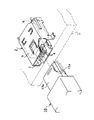
図3及び図4は射出成形される前記内部絶縁体13の詳細を示し、内部絶縁体13の本体部13aに形成されるコンタクタ収容溝16A,16Bの深さは、図4から理解されるように、それらの整列方向に隣り合ったものを交互に異ならせてあるから、これらのコンタクタ収容溝16A,16B中にコンタクタ11の接続端部11bを組み込むと、各接続端部11bは所謂”チドリ”状に配列されることになる。
したがって、これらのコンタクタ11の接続端部11bにハンダ付けされるコンタクタ収容溝16A,16Bの芯線17aも当然に所謂”チドリ”状配置となる。
【0014】
また、内部絶縁体13の本体部13aの下部には薄肉ヒンジ13bを介して図3中A方向に折り曲げる折返し部13cが一体成形され、同薄肉ヒンジ13bから折り曲げることができる前記折返し部13cの表面には前記コンタクタ挿通孔23にそれぞれ挿入できる小さな複数の盲突起20が一体成形され、これらの盲突起20を対応コンタクタ挿通孔23に挿入することにより、コンタクタ挿通孔23の孔を塞ぐことができる。
【0015】
本体部13aには同薄肉ヒンジ13bの両側に位置する一対のロック爪13dが一体成形され、これらのロック爪13dに対応した前記折返し部13cの左右には矩形枠状のストライカ13eが一体成形される。
このため、折返し部13cを折り曲げて盲突起20を対応コンタクタ挿通孔23に挿入して、同折返し部13cを本体部13aの中間表面に強く押し付けると、ロック爪13dがストライカ13e中に落ち込み、本体部13aと折返し部13cとの関係が固定されるので、コンタクト挿通孔23は盲突起20により完全に塞がれ、盲突起20がコンタクタ挿通孔23から不容易に抜け出して、同コンタクタ挿通孔23中に外部絶縁モールド19の樹脂が侵入するのを確実に防止できる。
【0016】
一方、前述した折返し部13cにはロック爪13dによる折返し部13cの固定時に本体部13aの接続部側に重ね合わされる接続部カバー13fが一体成形してある。即ち、この接続部カバー13fの表面には、前述したコンタクタ収容溝16A,16Bの内の浅いコンタクタ収容溝16Aに対応した位置にありかつ隣り合ったコンタクタ収容溝16A,16B間に跨がった幅広溝22が形成され、浅いコンタクタ収容溝16A中の接続端部11bにハンダ付けされる前記芯線17aがこれらの幅広溝22中に配置される。
また、深いコンタクタ収容溝16Bの接続端部11bにハンダ付けされる芯線17aは接続部カバー13fの押え部11gにより対応コンタクタ収容溝16B中からの飛び出しを防止されるから、コンタクタ11の接続端部11bにハンダ付けされる隣り合った各芯線17aは、上下に完全に分離され、互いの不容易な接触を未然に阻止されることになる。
【0017】
図示実施例によるコネクタプラグ10は、以上のような構造であるから、内部絶縁体13のコンタクタ収容溝16A,16Bにコンタクタ11を挿入し、各接続端部11bに接続コード17の芯線17aをハンダ付けした後、内部絶縁体13をシールドケース15中に位置し、同シールドケース15の開放部をシールドカバー18で覆って、シールドケース15及びシールドカバー18の外囲に外部絶縁モールド19を成形することにより完成される。このモールド成形時には、シールドケースカバー内の接続室24内にも樹脂は高圧で侵入する。
内部絶縁体13にコンタクタ11を取り付ける工程では、各コンタクタ11をコンタクト挿通孔23に挿通させ、コンタクタ収容溝16A,16B,16Cにそれぞれ挿入した後、薄肉ヒンジ13bから折返し部13cを内部絶縁体13の本体部13aに向かって180度折り返し、盲突起20を対応コンタクト挿通孔23に挿入して、同折返し部13cを本体部13aに強く押し付けるだけでロック爪13dがストライカ13eに落ち込み、外部絶縁モールド19の樹脂が侵入するおそれのあるコンタクト挿通孔23の隙間をなくすことができる。
【0018】
また、ロック爪13dによる折返し部13cの固定状態では、図4に示すように、本体部13aの下面が接続部カバー13fで覆われるから、各コンタクタ収容溝16A,16B中の接続端部11bにハンダ付けされる接続コード17の芯線17aが同接続部カバー13fで完全に覆われると同時に、隣り合った接続端部11bが同接続部カバー13fに形成される幅広溝22及び深いコンタクタ収容溝16B中に分離された状態で位置されるから、コンタクタ11及びコンタクタ収容孔16A,16Bの配列ピッチを小さくしても、隣り合った接続端部11b及び芯線17aの短絡はなく、コネクタプラグ10の小型化を図ることができる。
【0019】
つまり、接続部カバー13fに形成される幅広溝22は、幅方向に隣り合ったコンタクタ収容孔16A,16B間に跨がった状態にあり、しかも浅いコンタクタ収容孔16Aのコンタクタ11にハンダ付けされた芯線17aを収容しており、また、深いコンタクタ収容孔16B中に位置される接続コード17の芯線17aは接続部カバー13fの押え部11bで各深いコンタクタ収容孔16Bからの抜け出しを阻止された状態にあるから、短絡はない。
【0020】
なお、前記実施例においては、本発明をコネクタプラグ10に適用した例を挙げたが、本発明はコネクタソケット2に適用してもよいのは、改めて指摘するまでもない。
そして、上記したように内部絶縁体13、接続コード17の組立後にシールドケース15に組み込まれた後、シールドカバー18で閉じられる。その後、プラグ部シールド15a以外の外面に外部絶縁モールド19がアウトサート成形される。この時の射出圧力は高圧である為、シールドケース15内の接続室24内に樹脂が侵入する事になるが、コンタクト挿通孔23及びプラグ側のコンタクト収容溝16Cに対しては、盲突起20によってコンタクト挿通孔23が塞がれている為、同樹脂が漏洩する事は防止される。
【0021】
【発明の効果】
以上の説明から明らかなように、本発明によれば、コンタクタを支持させる内部絶縁体に対して折返し部を一体成形し、同折返し部から突起させる盲突起をコンタクタ収容溝に挿入して同コンタクタ挿通孔に形成される隙間をなくすから、外部絶縁モールドの樹脂がコンタクタ挿通孔に侵入するのを未然に防止できる。
この折返し部は内部絶縁体の成形時に本体部に一体に成形するから、製造原価が割高となったり、ピンセット等の特別の工具を用いたり、取り落として紛失する不都合を解消できる。
また、請求項3の発明のように、内部絶縁体の本体部と折返し部との間にロック手段を設けることにより、盲突起でコンタクタ収容孔を塞いだ状態に確実に保つことができ、そして、折返し部に対して接続部カバーを一体に成形しておくことにより、コンタクタにハンダ付けされた芯線を同接続部カバーで保護状態における利点がある。
【図面の簡単な説明】
【図1】一部を切欠いて示す本発明による小型コネクタの斜視図である。
【図2】同小型コネクタの全体断面図である。
【図3】同小型コネクタに用いる内部絶縁体の一部切欠き拡大斜視図である。
【図4】図2の4−4線に沿う拡大断面図である。
【符号の説明】
1 プリント配線基板
2 コネクタソケット
3 挿入口
10 コネクタプラグ
11 コンタクタ
13 内部絶縁体
13a 本体部
13b 薄肉ヒンジ
13c 折返し部
13d ロック爪
13e ストライカ
13f 接続部カバー
15 シールドケース
16A,16B,16C コンタクタ収容溝
17 接続コード
17a 芯線
18 シールドカバー
19 外部絶縁モールド
20 盲突起
22 幅広溝
23 コンタクト挿通孔[0001]
TECHNICAL FIELD OF THE INVENTION
The present invention relates to an electrical connector, and more particularly, to a small connector used for connecting electronic devices such as a personal computer.
[0002]
[Background Art]
As is well known, in a connector plug used to be connected to a connector socket mounted on a printed wiring board or the like, the outside of an internal insulator supporting a plurality of contact conductors (contactors) is covered with a shield case, and The outer surface of the connection cord side end is covered with an external insulating mold.
[0003]
By the way, in the case of such an outsert molding of the external insulating mold, since the injection pressure of the molding resin reaches several tens of kg / cm 2, the injection pressure of the molding resin is increased from the gap of the shield case located in the injection mold to the inside of the shield case. External insulation molding resin may enter and cause a number of failures.
In particular, a plurality of contactor receiving holes for inserting and supporting contact conductors (contactors) are formed in the internal insulator inside the connector plug, and the resin of the external insulating mold is partially filled in these contactor receiving holes. If it enters, the surface of the contact conductor (contactor) may be covered with resin, which may cause poor contact or the like.
[0004]
For this reason, in the manufacturing process of the connector plug having the above-described structure, the entrance of the contactor housing hole is covered with a sealing tape or a blind plug of another component before forming the external insulating mold, and the contactor housing hole is formed. This prevents the mold resin from flowing into it.
[0005]
However, such a method of closing the contactor accommodating hole with a seal tape or a blind plug is a precision operation using tweezers or the like that handles very small parts, so that the operation efficiency is poor and the operation requires skill. was there.
[0006]
[Problems to be solved by the invention]
An object of the present invention is to provide a contactor housing hole easily without forming a special blind plug or the like and prior to forming an external insulating mold, in view of the above-described problem of manufacturing a conventional small connector. An object of the present invention is to obtain a small connector having a structure that can be closed.
[0007]
[Means for Solving the Problems]
In order to achieve this object, the present invention relates to a method of manufacturing a semiconductor device comprising the steps of: (a) enclosing an outer portion of an inner insulator supporting a plurality of contact conductors to be brought into contact with a contact conductor of a mating connector with a shield case; In a small connector that covers the outer conductor with an outer insulating mold, a folded portion is integrally formed on the inner insulator via a thin hinge, a plurality of blind projections are formed on the inner insulator in a protruding state, and the contact conductor for attaching the contact conductor is provided. It is an object of the present invention to provide a small connector in which the blind protrusions are inserted into the insertion holes to prevent resin leakage during molding of the external insulating mold.
[0008]
In the description of the preferred embodiments of the invention described below,
1) a structure in which locking means for keeping the blind projection inserted into the contact conductor insertion hole is formed between the body portion of the internal insulator and the folded portion;
2) The lock means includes a pair of lock claws integrally formed on either side of the main body portion and the folded portion, and the other side of the main body portion and the folded portion corresponding to the lock claws. A structure comprising a striker integrally molded with
3) a structure in which a connection portion cover that covers an end portion of the contact conductor to which a connection cord is soldered is formed integrally with the folded portion, and a soldered portion of the connection cord is protected by the connection portion cover;
4) The structure is described in which the small connector is a connector plug inserted into an insertion opening of a mating connector socket mounted on a printed wiring board.
[0009]
BEST MODE FOR CARRYING OUT THE INVENTION
Hereinafter, embodiments of the present invention will be described in detail with reference to the drawings.
The illustrated embodiment is an embodiment in which the present invention is applied to a connector plug. As can be understood from FIGS. 1 and 2, a connector plug 2 is inserted into an insertion opening 3 of a connector socket 2 mounted on a printed wiring board 1. The ten plug portions 10a are detachably inserted.
[0010]
That is, the connector socket 2 includes an insulator mold 5 that supports a plurality of contacts 4 aligned in the width direction. The insulator mold 5 is formed in a metallic shield case 6 that is bent into a flat rectangular tube shape. And the shield case 6 shields the influence of an external electric field and an external magnetic field.
[0011]
The connector plug 10 having the plug portion 10a has an internal insulator 13 that supports a plurality of contactors 11 (contact conductors) aligned in a direction perpendicular to the paper surface of FIG. 2. It is surrounded by a shield case 15 formed by bending a metal plate.
In other words, the inner insulator 13 to be injection-molded has the plurality of contactor receiving grooves 16A and 16B, the contact insertion holes 23, and the plug-part-side contact receiving grooves 16C extending in the length direction of the plurality of cord connection portions 15 formed therein. The contactor 11 is located in each of the contactor accommodating grooves 16A and 16B, the contact insertion hole 23, and the plug-side contact accommodating groove 16C, but is inserted into the contactor accommodating grooves 16A and 16B. The contact end 11a and the connection end 11b of each contactor 11 in the closed state are provided on the surface of the contactor accommodation grooves 16A and 16B and the contact accommodation groove 16C for elastic contact with the contact 4 and soldering to the core wire 17a of the connection cord 17. From the exposed state.
[0012]
The shield case 15 has a plug shield 15a that matches the cross-sectional shape of the insertion opening 3 of the connector socket 2 described above, and a cord connection portion 15b having an enlarged cross-sectional shape is continuously provided at the rear end of the plug shield 15a. The surface of the connection portion 15b for introducing the tip of the connection cord 17 is closed by the shield cover 18 after the internal insulator 13 and the connection cord 17 are received.
Further, in the manufacturing process of the connector plug 10, after assembling the shield case 15, the inner insulator 13, and the connection cord 17, these are arranged in an injection molding die, and external insulation is provided on an outer surface other than the plug shield 15a described above. The mold 19 is outsert molded.
[0013]
3 and 4 show details of the inner insulator 13 which is injection-molded. The depth of the contactor housing grooves 16A and 16B formed in the main body 13a of the inner insulator 13 can be understood from FIG. In addition, since those adjacent to each other in the alignment direction are alternately different, if the connection end portions 11b of the contactor 11 are incorporated into these contactor accommodation grooves 16A, 16B, each connection end portion 11b becomes a so-called ".
Therefore, the core wires 17a of the contactor housing grooves 16A and 16B soldered to the connection end portions 11b of these contactors 11 also naturally have a so-called "stagnant" arrangement.
[0014]
A folded portion 13c is formed integrally with a lower portion of the main body portion 13a of the internal insulator 13 via a thin hinge 13b in the direction A in FIG. 3, and the surface of the folded portion 13c can be bent from the thin hinge 13b. A plurality of small blind projections 20 each of which can be inserted into the contactor insertion hole 23 are integrally formed. By inserting these blind projections 20 into the corresponding contactor insertion hole 23, the hole of the contactor insertion hole 23 can be closed. .
[0015]
A pair of lock claws 13d located on both sides of the thin hinge 13b are integrally formed on the main body 13a, and a rectangular frame-shaped striker 13e is integrally formed on the left and right sides of the folded portion 13c corresponding to the lock claws 13d. You.
Therefore, when the folded portion 13c is bent and the blind projection 20 is inserted into the corresponding contactor insertion hole 23, and the folded portion 13c is strongly pressed against the intermediate surface of the main body 13a, the lock claw 13d falls into the striker 13e, Since the relationship between the portion 13a and the folded portion 13c is fixed, the contact insertion hole 23 is completely closed by the blind projection 20, and the blind projection 20 easily comes out of the contactor insertion hole 23, and the contactor insertion hole 23 It is possible to reliably prevent the resin of the external insulating mold 19 from entering the inside.
[0016]
On the other hand, a connection portion cover 13f that is superimposed on the connection portion side of the main body portion 13a when the folded portion 13c is fixed by the lock claw 13d is integrally formed with the above-mentioned folded portion 13c. That is, on the surface of the connecting portion cover 13f, the contactor receiving groove 16A is located at a position corresponding to the shallow contactor receiving groove 16A of the contactor receiving groove 16A, and straddles between the adjacent contactor receiving grooves 16A, 16B. Wide grooves 22 are formed, and the core wires 17a to be soldered to the connection ends 11b in the shallow contactor housing grooves 16A are arranged in these wide grooves 22.
Further, since the core wire 17a soldered to the connection end portion 11b of the deep contactor accommodation groove 16B is prevented from protruding from the corresponding contactor accommodation groove 16B by the holding portion 11g of the connection portion cover 13f, the connection end portion of the contactor 11 is prevented. Adjacent core wires 17a which are soldered to 11b are completely separated from each other in the vertical direction, so that the easy contact between them is prevented.
[0017]
Since the connector plug 10 according to the illustrated embodiment has the above-described structure, the contactor 11 is inserted into the contactor receiving grooves 16A and 16B of the internal insulator 13 and the core wire 17a of the connection cord 17 is soldered to each connection end 11b. After the attachment, the inner insulator 13 is positioned in the shield case 15, the open part of the shield case 15 is covered with the shield cover 18, and the outer insulating mold 19 is formed around the shield case 15 and the shield cover 18. It is completed by doing. At the time of this molding, the resin enters the connection chamber 24 in the shield case cover at a high pressure.
In the step of attaching the contactor 11 to the internal insulator 13, each contactor 11 is inserted into the contact insertion hole 23 and inserted into each of the contactor accommodating grooves 16A, 16B, 16C, and then the folded portion 13c is turned from the thin hinge 13b to the internal insulator 13. Fold 180 degrees toward the main body 13a, insert the blind projection 20 into the corresponding contact insertion hole 23, and press the folded part 13c strongly against the main body 13a. The gap of the contact insertion hole 23 where the resin 19 may enter can be eliminated.
[0018]
In a state where the folded portion 13c is fixed by the lock claw 13d, as shown in FIG. 4, the lower surface of the main body portion 13a is covered with the connection portion cover 13f, so that the connection end portion 11b in each of the contactor accommodating grooves 16A and 16B is provided. The core wire 17a of the connection cord 17 to be soldered is completely covered with the connection portion cover 13f, and the adjacent connection end portions 11b are formed in the wide connection groove 22 and the deep contactor accommodation groove 16B formed in the connection portion cover 13f. Even if the arrangement pitch of the contactor 11 and the contactor receiving holes 16A and 16B is reduced, there is no short circuit between the adjacent connection end portions 11b and the core wires 17a, and the connector plug 10 is small. Can be achieved.
[0019]
That is, the wide groove 22 formed in the connection portion cover 13f is in a state of straddling between the contactor housing holes 16A and 16B adjacent in the width direction and is soldered to the contactor 11 of the shallow contactor housing hole 16A. The core wire 17a of the connection cord 17 located in the deep contactor housing hole 16B is prevented from coming out of each deep contactor housing hole 16B by the pressing portion 11b of the connection portion cover 13f. There is no short circuit because it is in the state.
[0020]
In the above embodiment, an example in which the present invention is applied to the connector plug 10 has been described. However, it is needless to point out that the present invention may be applied to the connector socket 2.
Then, after assembling the internal insulator 13 and the connection cord 17 as described above, the assembly is assembled into the shield case 15 and then closed by the shield cover 18. Thereafter, the outer insulating mold 19 is outsert molded on the outer surface other than the plug shield 15a. Since the injection pressure at this time is high, the resin will enter the connection chamber 24 in the shield case 15. However, the blind projection 20 is not inserted into the contact insertion hole 23 and the contact receiving groove 16 </ b> C on the plug side. Since the contact insertion hole 23 is closed by this, the resin is prevented from leaking.
[0021]
【The invention's effect】
As is apparent from the above description, according to the present invention, the folded portion is integrally formed with the internal insulator for supporting the contactor, and the blind projection which is projected from the folded portion is inserted into the contactor accommodating groove to thereby form the contactor. Since the gap formed in the insertion hole is eliminated, it is possible to prevent the resin of the external insulating mold from entering the contactor insertion hole.
Since the folded portion is formed integrally with the main body when the internal insulator is formed, it is possible to eliminate the disadvantage that the manufacturing cost is increased, a special tool such as tweezers is used, or the folded portion is lost by being dropped.
Further, by providing the locking means between the main body portion and the folded portion of the internal insulator as in the invention of claim 3, it is possible to reliably keep the contactor housing hole closed by the blind projection, and By forming the connection portion cover integrally with the folded portion, there is an advantage in that the core wire soldered to the contactor is protected by the connection portion cover.
[Brief description of the drawings]
FIG. 1 is a perspective view of a small connector according to the present invention, partially cut away.
FIG. 2 is an overall sectional view of the small connector.
FIG. 3 is an enlarged perspective view of a partially cut-away portion of an internal insulator used in the small connector.
FIG. 4 is an enlarged sectional view taken along line 4-4 of FIG. 2;
[Explanation of symbols]
DESCRIPTION OF SYMBOLS 1 Printed wiring board 2 Connector socket 3 Insertion opening 10 Connector plug 11 Contactor 13 Internal insulator 13a Main part 13b Thin hinge 13c Folding part 13d Lock claw 13e Striker 13f Connection part cover 15 Shield case 16A, 16B, 16C Contactor accommodation groove 17 Connection Cord 17a Core wire 18 Shield cover 19 External insulation mold 20 Blind protrusion 22 Wide groove 23 Contact insertion hole