JP3554884B2 - Filtration device and filtration method - Google Patents
Filtration device and filtration method Download PDFInfo
- Publication number
- JP3554884B2 JP3554884B2 JP2000001358A JP2000001358A JP3554884B2 JP 3554884 B2 JP3554884 B2 JP 3554884B2 JP 2000001358 A JP2000001358 A JP 2000001358A JP 2000001358 A JP2000001358 A JP 2000001358A JP 3554884 B2 JP3554884 B2 JP 3554884B2
- Authority
- JP
- Japan
- Prior art keywords
- chamber
- filtrate
- inflow
- outflow
- vent
- Prior art date
- Legal status (The legal status is an assumption and is not a legal conclusion. Google has not performed a legal analysis and makes no representation as to the accuracy of the status listed.)
- Expired - Lifetime
Links
Images


Description
【0001】
【発明の属する技術分野】
本発明は、密閉条件下で汚濁液を濾材に通液して固液分離する濾過装置及び濾過法に属する。
【0002】
【従来の技術】
有機溶剤等の有害物質に含まれる固体分を固液分離するとき、有害成分が大気中に放出されることを防止するため、密閉型の濾過装置で固液分離を行う。更に、液体の粘性が高いとき、長時間濾過し続けると、固体分が濾材の細孔を閉塞して濾過能力を低下させるため、濾過方向と逆に通液して固体分を濾材から除去する必要があるが、濾材に粘着成分が固着するので、完全に濾過能力を回復することができない。このような有害かつ高粘度の汚濁液の固液分離を行うとき、装置全体が密閉され、固液分離した固体分を濾材と共に簡易に除去できるフィルタプレスが用いられる
【0003】
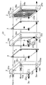
図6〜図8に示すフィルタプレス(30)は、密閉された濾過室(4)を形成する矩形のフレーム(1)及び隔壁板(2)と、濾過室(4)を分割して、図7に示すように複数の流入室(5)及び流出室(6)を形成する濾材(3)と、隔壁板(2)の下角部にそれぞれ取り付けられかつ流入室(5)に連絡する流入管(18a)と、隔壁板(2)の上角部にそれぞれ取り付けられかつ流出室(6)に連絡する流出管(19a)と、流入室(5)に連絡してフレーム(1)に形成された原液ベント(15a)と、流出室(6)に連絡して隔壁板(2)に形成された濾液ベント(16a)とを備える。図8に示すように、隔壁板(2)は、濾材(3)を支持する多孔板(21)と、多孔板(21)を支持する突出部(2a)と、濾液ベント(16a)に濾液(6a)を搬送する溝部(2b)とを備える。
【0004】
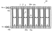
フィルタプレス(30)は、図6の縦断面図である図7の矢印に示すように、原液(5a)を流入管(18a)、原液連通路(25a)及び原液ベント(15a)を通じて下部から流入室(5)内に供給し、濾材(3)で濾過して流出室(6)に濾液(6a)を供給する。その濾液(6a)を流出室(6)の上部から濾液ベント(16a)、濾液連通路(26a)及び流出管(19a)を通じてフィルタプレス(30)の外部に取り出す。濾過を終了した後、濾材(3)の表面(3a)には固体分が形成されるので、フレーム(1)と隔壁板(2)とを隔離させて、形成された固体分を濾材(3)と共に除去することができる。
【0005】
【発明が解決しようとする課題】
前記のようにフィルタプレス(30)は、密閉下で濾過して固液分離を行い、濾材(3)の表面(3a)に形成された固体分を容易に除去できるので、高粘性で有害物質を含む原液(5a)の濾過に適する。ところが、前記フィルタプレス(30)は、濾過するとき流入室(5)及び流出室(6)が完全に密閉されるため、原液(5a)に含まれる空気、揮発性物質等の気体により、流入室(5)及び流出室(6)の上部に気体層が形成される。流出室(6)に形成された気体層の気体は、濾液ベント(16a)が流出室(6)の上部に形成されるため、濾液ベント(16a)から濾液(5a)と共に大部分が排出されるが、流入室(5)に形成された気体層の気体は、フィルタプレス(30)の外部に排出されることなく除々に拡大する。これにより、濾過面積が減少し、気体に接触していない濾材(3)の濾過部分に原液(5a)中の固体分が集中して捕捉され、フィルタプレス(30)の濾過圧力上昇及び濾過量低下を招く。
そこで、本発明は、濾過面積を常に最大に維持することにより濾過能力の低下を防ぎ、濾過時間を延長することを目的とする。
【0006】
【課題を解決するための手段】
本発明による濾過装置は、密閉された濾過室(4)を形成する外枠(1, 2)と、濾過室(4)を分割して流入室(5)及び流出室(6)を形成する濾材(3)と、外枠(1, 2)に取り付けられかつ流入室(5)に連絡する流入管(18a)と、外枠(1, 2)に取り付けられかつ流出室(6)に連絡する流出管(19a)とを備え、濾材(3)により流入室(5)内に供給される原液(5a)を濾過して流出室(6)内に供給される濾液(6a)を生成し、流出室(6)から濾液(6a)を取り出す。本発明では、流入室(5)に連絡して外枠(1)に形成された第1及び第2の原液ベント(15a, 15b)と、第2の原液ベント(15b)を介して流入室(5)に接続されかつ排気バルブ(7a)を有する排気装置(7)とを備え、流入管(18a)から第1の原液ベント(15a)を通じて流入室(5)内に原液(5a)を供給する際に、第2の原液ベント(15b)及び排気装置(7)を通じて流入室(5)内に滞留する気体(10)を排出する。
【0007】
第2の原液ベント(15b)を介して、流入室(5)に排気装置(7)を接続することにより、流入室(5)に滞留する気体(10)を確実に除去することができる。密閉された濾過室(4)内に濾材(3)を配置して濾過する濾過装置では、原液(5a)に含まれる空気及び揮発性物質により、流入室(5)の上部に気体層が形成される。気体層は、除々に拡大し濾過面積を減少させて、濾過圧力の上昇及び濾過量の低下を助長する。従って、排気装置(7)を設けることにより、原液(5a)を供給する際に、流入室(5)内に滞留する気体層の気体(10)を流入室(5)から排出して、濾材(3)の表面全体を利用した濾過が可能となる。
【0008】
本発明による濾過法は、フレーム(1)と、濾材(3)を支持する隔壁板(2)とを交互に複数密着させて、流入室(5)及び流出室(6)からなる密閉された濾過室(4)を複数形成する工程と、流入室(5)に原液(5a)を供給すると共に、流入室(5)に滞留する気体(10)を排出する工程と、濾材(3)により流入室(5)内の原液(5a)を濾過して流出室(6)内に濾液(6a)を生成すると共に、流出室(6)に滞留する気体(10)を除去する工程と、濾過終了後、原液(5a)の供給を停止して濾過室(4)から原液(5a)及び濾液(6a)を排出する工程と、フレーム(1)と隔壁板(2)とを隔離させて、濾材(3)で分離された固体分又固体分が付着した濾材(3)を除去する工程とを含む。
【0009】
また、流入室(5)に滞留する気体(10)を流入室(5)の上部から排出する工程と、流出室(6)に滞留する気体(10)を流出室(6)の上部から排出する工程と、流入室(5)及び流出室(6)から気体(10)を排出した後、原液(5a)を流入室(5)の上部から供給し、濾液(6a)を流出室(6)の上部から取り出す工程とを含んでもよい。
【0010】
【発明の実施の形態】
以下、本発明による濾過装置の実施の形態を図1〜図5により説明する。
【0011】
図1に示す本発明による濾過装置は、密閉された濾過室(4)を形成する外枠(1,2)と、濾過室(4)を分割して流入室(5)及び流出室(6)を形成する濾材(3)と、外枠(1)に取り付けられかつ流入室(5)に連絡する流入管(18a)と、外枠(2)に取り付けられかつ流出室(6)に連絡する流出管(19a)とを備える。本発明では更に、流入室(5)に連絡して外枠(1)に形成された第1及び第2の原液ベント(15a, 15b)と、第2の原液ベント(15b)を介して流入室(5)に接続されかつ排気バルブ(7a)を有する排気装置(7)とを備える。これにより、流入管(18a)から第1の原液ベント(15a)を通じて流入室(5)内に原液(5a)を供給する際に、第2の原液ベント(15b)及び排気装置(7)を通じて流入室(5)内に滞留する気体(10)を濾過装置から排出できる。また、流出室(6)に連絡して外枠(2)に形成された第1及び第2の濾液ベント(16a, 16b)と、第2の濾液ベント(16b)を介して流出室(6)に接続されかつ排気バルブ(8a)を有する排気装置(8)とを備えることにより、第1の濾液ベント(16a)を通じて流出室(6)内から流出管(19a)に濾液(6a)を取り出す際に、第2の濾液ベント(16b)及び排気装置(8)を通じて流出室(6)内に滞留する気体(10)を排出できる。
【0012】
本実施の形態による濾過装置は、外枠(1, 2)には、流入室(5)及び流出室(6)に連絡する補助流入管(18b)及び補助流出管(19b)を備え、補助流入管(18b)及び補助流出管(19b)はそれぞれ第2の原液ベント(15b)及び第2の濾液ベント(16b)に接続される。流入室(5)及び流出室(6)内に滞留する気体(10)を排出した後、排気バルブ(7a, 8a)を閉じて、流入管(18a)と共に補助流入管(18b)から原液(5a)を流入室(5)に供給し、流出管(19a)と共に補助流出管(19b)から流出室(6)内の濾液(6a)を取り出す。
【0013】
図2〜図5は、本発明による濾過装置の実施の形態であるフィルタプレス(20)を示す。本実施の形態によるフィルタプレス(20)では、外枠(1, 2)は、フレーム(1)と、フレーム(1)の両側に固着された一対の隔壁板(2)とを備え、フレーム(1)の内側に形成された流入室(5)は、各隔壁板(2)の内側に形成された流出室(6)に対して濾材(3)を介して隣接する。濾材(3)は矩形の紙、不織布、織布及び金網の1種又は2種以上を使用し、原液(5a)中に含まれる固体分の含有量、粒径、化学成分等により濾材(3)の細孔径が選択される。フレーム(1)及び隔壁板(2)は、それぞれ上部に第2の原液ベント(15b)及び第2の濾液ベント(16b)を有し、流入室(5)及び流出室(6)に滞留した気体(10)が効率よく排気装置(7, 8)から排出される。排気装置(7, 8)の排気バルブ(7a, 8a)は、電動バルブ、空動バルブ、手動バルブ又は気体のみを通す自動空気抜きバルブを用いることができる。図2〜図4に示す排気バルブ(7a, 8a)及びバルブ(31〜34)は、白丸を付したバルブが開いた状態を示し、黒丸を付したバルブが閉じた状態を示す。フレーム(1)及び隔壁板(2)は矩形に形成され、フレーム(1)の異なる角部に第1及び第2の原液ベント(15a,15b)を設け、隔壁板(2)の異なる角部に第1及び第2の濾液ベント(16a, 16b)を設ける。
【0014】
図5に示すように隔壁板(2)は、濾材(3)を支持する補強材(11)を一方又は両方の主面に備え、補強材(11)を支持する突出部(2a)と、濾液(6a)を第1及び第2の濾液ベント(16a, 16b)に搬送する格子状に形成された溝部(2b)とを備える。補強材(11)は、従来、図8に示すように多孔板(21)を用いていたが、空隙率の大きい金網又はパンチングメタルを用いることにより、抵抗を小さくして通液性を向上できる。
【0015】
本実施の形態では、補強材(11)を一方の主面に備えかつ補強材(11)を対向させた一対の隔壁板(2)間にフレーム(1)と、両方の主面に補強材(11)を備える隔壁板(2)とを濾材(3)を介して交互に複数密着させる。これにより、図4に示すように複数の流入室(5)及び流出室(6)が交互に形成される。また、フレーム(1)、隔壁板(2)及び濾材(3)を密着させると、それぞれ4箇所の角部を通る第1及び第2の原液連通路(25a, 25b)並びに第1及び第2の濾液連通路(26a, 26b)が形成される。第1及び第2の原液連通路(25a, 25b)は、流入管(18a)及び補助流入管(18b)と第1及び第2の原液ベント(15a, 15b)とを接続する。第1及び第2の濾液連通路(26a, 26b)は、流出管(19a)及び補助流入管(19b)と第1及び第2の濾液ベント(16a, 16b)とを接続する。
【0016】
前記フィルタプレス(20)を用いた濾過法は、最初に、フレーム(1)と、濾材(3)が支持された隔壁板(2)とを図示しない油圧シリンダで交互に複数密着させて、図4に示すように流入室(5)及び流出室(6)からなる密閉された濾過室(4)を複数形成する。次に、流入室(5)に原液(5a)を供給すると共に、流入室(5)に滞留する気体(10)を排出する。原液(5a)は、図示しないポンプにより0.3〜3.5MPaの圧力で、図2に示すように流入管(5a)、第1の原液連通路(25a)及び第1の原液ベント(15a)を通じて流入室(5)に供給される。流入室(5)内及び原液(5a)に含まれる気体(10)は、流入室(5)の上方に移動し、流入室(5)の上部に形成された第2の原液ベント(15b)、第2の原液連通路(25b)及び排気バルブ(7a)を通じてフィルタプレス(20)の外部に排出される。
【0017】
流入室(5a)内に供給された原液(5a)は、濾材(3)で濾過されて流出室(6)内に濾液(6a)を生成すると共に、流出室(6)に滞留する気体(10)を除去する。流出室(6)内及び濾液(6a)に含まれる気体(10)は、流出室(6)の上方に移動し、流出室の上部に形成された第2の濾液ベント(16b)、第2の濾液連通路(26b)及び排気バルブ(8a)を通じて排出される。排気バルブ(7a, 8a)から排出される気体(10)中に有害物質を含むときは、有害物質を完全に除去した後、大気中に放出する。
【0018】
図2及び図3の横断面図である図4に示すように、流出室(6)内に生成された濾液(6a)は、第1の濾液ベント(16a)、第1の濾液連通路(26a)及び流出管(19a)を通じて取り出される。このとき、図2に示すように、流入管(18a)及び流出管(19a)に接続されたバルブ(31)及び(33)は開いた状態で、補助流入管(18b)及び補助流出管(19b)に接続されたバルブ(32)及び(34)は閉じた状態であるが、流出管(19a)に接続されたバルブ(33)を絞って通液量を抑えてもよい。これにより、流入室(5)及び流出室(6)に滞留した気体(10)を短時間で排出できる。
【0019】
気体(10)を排出した後、原液(5a)を流入室(5)の下部から供給すると共に上部からも供給し、濾液(6a)を流出室(6)の下部から取り出すと共に上部からも取り出す。即ち、図3に示すように、排気バルブ(7a)を閉じバルブ(32)を開いて、原液(5a)を補助流入管(18b)、第2の原液連通路(25b)及び第2の原液ベント(15b)を通じて流入室(5)に供給し、排気バルブ(8a)を閉じバルブ(34)を開いて、濾液(6a)を第2の濾液ベント(16b)、濾液連通路(26b)及び補助流出管(19b)を通じて流出室(6)から取り出す。
【0020】
このように、流入管(18a)及び補助流入管(18b)から原液(5a)を供給し、流出管(19a)及び補助流出管(19b)から濾液(5a)を取り出し、濾過が終了した後、原液(5a)の供給を停止して濾過室(4)から原液(5a)及び濾液(6a)を排出する。原液(5a)及び濾液(6a)は、それぞれ流入管(18a)及び流出管(19a)から排出される。完全に排出するため、流入管(18a)及び流出管(19a)が接続された隔壁板(2)の底面を下方に下げて、第1の原液連通路(25a)及び第1の濾液連通路(26a)を傾斜させてもよい。
【0021】
原液(5a)及び濾液(6a)を排出後、フレーム(1)と隔壁板(2)とを隔離させて、濾材(3)で分離された固体分又固体分が付着した濾材(3)を除去する。図5に示す濾材(3)の表面(3a)に形成される固体分の粘性が低く除去が容易であれば、濾材(3)から固体分を剥がして除去すればよい。一方、粘性の高い固体分を多く含むとき、固体分と共に濾材(3)を補強材(11)から剥がすことにより、容易に固体分を除去することができる。再度濾過を開始するときは、濾材(3)を補強材(11)の表面に配置して又は配置されている場合にはそのままの状態でフレーム(1)と、隔壁板(2)とを密着させて原液(5a)を供給する。
【0022】
【発明の効果】
本発明では、排気装置を設けることにより濾材の濾過面を有効に活用できるので、一定流量における濾過時間を延長してランニングコストの低減を図ることができる。
【図面の簡単な説明】
【図1】本発明による濾過装置を示す断面図
【図2】本発明の実施の形態における排気状態を示す分解図
【図3】本発明の実施の形態における排気後の濾過状態を示す分解図
【図4】本発明の実施の形態を示す横断面図
【図5】本発明の実施の形態を示す部分拡大図
【図6】従来の濾過装置における濾過状態を示す分解図
【図7】従来の濾過装置の縦断面図
【図8】従来の濾過装置の部分拡大図
【符号の説明】
(1)・・外枠(フレーム)、 (2)・・外枠(隔壁板)、 (2a)・・突出部、 (2b)・・溝部、 (3)・・濾材、 (3a)・・表面、 (4)・・濾過室、 (5)・・流入室、 (5a)・・原液、 (6)・・流出室、 (6a)・・濾液、 (7, 8)・・排気装置、 (7a, 8a)・・排気バルブ、 (10)・・気体、 (11)・・補強材、 (15a)・・第1の原液ベント(原液ベント)、 (15b)・・第2の原液ベント、 (16a)・・第1の濾液ベント(濾液ベント)、 (16b)・・第2の濾液ベント、 (18a)・・流入管、 (18b)・・補助流入管、 (19a)・・流出管、 (19b)・・補助流出管、 (20)・・フィルタプレス、 (21)・・多孔板、 (25a)・・第1の原液連通路(原液連通路)、 (25b)・・第2の原液連通路、 (26a)・・第1の濾液連通路(濾液連通路)、 (26b)・・第2の濾液連通路、 (30)・・フィルタプレス、 (31〜34)・・バルブ、[0001]
TECHNICAL FIELD OF THE INVENTION
The present invention relates to a filtration apparatus and a filtration method for passing a contaminated liquid through a filter medium under a closed condition to perform solid-liquid separation.
[0002]
[Prior art]
When performing solid-liquid separation of a solid component contained in a harmful substance such as an organic solvent, the solid-liquid separation is performed by a closed filtration device in order to prevent harmful components from being released into the atmosphere. Furthermore, when the viscosity of the liquid is high, if the filtration is continued for a long time, the solids block the pores of the filter medium and reduce the filtration ability, so that the liquid is passed in the opposite direction to the filtration direction to remove the solids from the filter medium. Although it is necessary, since the adhesive component adheres to the filter medium, the filtration ability cannot be completely restored. When such harmful and high-viscosity contaminated liquid is subjected to solid-liquid separation, a filter press is used, in which the entire apparatus is sealed and the solid component separated from solid and liquid can be easily removed together with a filter medium.
The filter press (30) shown in FIGS. 6 to 8 divides a filtration frame (4) from a rectangular frame (1) and a partition plate (2) forming a sealed filtration chamber (4). As shown in FIG. 7, a filter medium (3) forming a plurality of inflow chambers (5) and an outflow chamber (6), and an inflow pipe attached to the lower corner of the partition plate (2) and communicating with the inflow chamber (5). (18a), an outflow pipe (19a) attached to the upper corner of the partition plate (2) and communicating with the outflow chamber (6), and formed on the frame (1) in communication with the inflow chamber (5). And a filtrate vent (16a) formed in the partition plate (2) in communication with the outflow chamber (6). As shown in FIG. 8, the partition plate (2) includes a perforated plate (21) supporting the filter medium (3), a projection (2a) supporting the perforated plate (21), and a filtrate vent (16a). And (6a) for transporting the groove.
[0004]
As shown by an arrow in FIG. 7 which is a longitudinal sectional view in FIG. 6, the filter press (30) feeds the stock solution (5a) from below through the inflow pipe (18a), the stock solution communication passage (25a) and the stock solution vent (15a). The filtrate (6) is supplied into the inflow chamber (5), filtered through the filter medium (3), and supplied to the outflow chamber (6). The filtrate (6a) is taken out of the filter press (30) from the upper part of the outflow chamber (6) through the filtrate vent (16a), the filtrate communication passage (26a) and the outflow pipe (19a). After the filtration is completed, solids are formed on the surface (3a) of the filter medium (3). Therefore, the frame (1) and the partition plate (2) are separated from each other, and the formed solids are separated from the filter medium (3). ) And can be removed.
[0005]
[Problems to be solved by the invention]
As described above, the filter press (30) performs solid-liquid separation by filtering in a closed state, and can easily remove solids formed on the surface (3a) of the filter medium (3). Suitable for filtration of the stock solution (5a) containing However, in the filter press (30), since the inflow chamber (5) and the outflow chamber (6) are completely sealed during filtration, the inflow chamber (5a) is inflowed by gas such as air and volatile substances contained in the stock solution (5a). A gas layer is formed above the chamber (5) and the outflow chamber (6). Most of the gas in the gas layer formed in the outflow chamber (6) is discharged together with the filtrate (5a) from the filtrate vent (16a) because the filtrate vent (16a) is formed above the outflow chamber (6). However, the gas in the gas layer formed in the inflow chamber (5) gradually expands without being discharged to the outside of the filter press (30). As a result, the filtration area is reduced, and the solids in the undiluted solution (5a) are concentrated and trapped in the filtration portion of the filter medium (3) that is not in contact with the gas, so that the filtration pressure and the filtration amount of the filter press (30) are increased. Causes a decline.
Therefore, an object of the present invention is to always maintain the filtration area at a maximum to prevent a decrease in filtration capacity and to extend the filtration time.
[0006]
[Means for Solving the Problems]
In the filtration device according to the present invention, an outer frame (1, 2) forming a sealed filtration chamber (4) and a filtration chamber (4) are divided to form an inflow chamber (5) and an outflow chamber (6). A filter medium (3), an inflow pipe (18a) attached to the outer frame (1, 2) and communicating with the inflow chamber (5), and an inflow pipe (18) attached to the outer frame (1, 2) and communicating with the outflow chamber (6). And an outflow pipe (19a) for filtering the undiluted solution (5a) supplied into the inflow chamber (5) by the filter medium (3) to produce a filtrate (6a) supplied to the outflow chamber (6). Then, the filtrate (6a) is taken out from the outflow chamber (6). In the present invention, the first and second undiluted liquid vents (15a, 15b) formed in the outer frame (1) in communication with the inflow chamber (5) and the inflow chamber through the second undiluted liquid vent (15b). An exhaust device (7) connected to (5) and having an exhaust valve (7a). The undiluted solution (5a) is introduced into the inflow chamber (5) from the inflow pipe (18a) through the first undiluted solution vent (15a). When supplying, the gas (10) staying in the inflow chamber (5) is discharged through the second stock solution vent (15b) and the exhaust device (7).
[0007]
By connecting the exhaust device (7) to the inflow chamber (5) through the second stock solution vent (15b), the gas (10) staying in the inflow chamber (5) can be reliably removed. In a filtration device in which a filter medium (3) is disposed in a closed filtration chamber (4) for filtration, a gas layer is formed above the inflow chamber (5) due to air and volatile substances contained in the stock solution (5a). Is done. The gas layer gradually expands and reduces the filtration area, which helps to increase the filtration pressure and decrease the filtration amount. Therefore, by providing the exhaust device (7), when supplying the undiluted solution (5a), the gas (10) of the gas layer stagnating in the inflow chamber (5) is discharged from the inflow chamber (5), and the filter medium is removed. Filtration using the entire surface of (3) becomes possible.
[0008]
In the filtration method according to the present invention, a plurality of frames (1) and partition plates (2) supporting a filter medium (3) are alternately brought into close contact with each other to form a sealed room comprising an inflow chamber (5) and an outflow chamber (6). A step of forming a plurality of filtration chambers (4), a step of supplying a stock solution (5a) to the inflow chamber (5), and a step of discharging gas (10) staying in the inflow chamber (5); Filtering the undiluted solution (5a) in the inflow chamber (5) to generate a filtrate (6a) in the outflow chamber (6) and removing gas (10) remaining in the outflow chamber (6); After the completion, the supply of the stock solution (5a) is stopped and the stock solution (5a) and the filtrate (6a) are discharged from the filtration chamber (4), and the frame (1) and the partition plate (2) are separated. Removing the solid matter separated by the filter medium (3) or the filter medium (3) to which the solid matter adheres.
[0009]
Further, a step of discharging the gas (10) staying in the inflow chamber (5) from above the inflow chamber (5) and a step of discharging the gas (10) staying in the outflow chamber (6) from above the outflow chamber (6). After discharging the gas (10) from the inflow chamber (5) and the outflow chamber (6), the undiluted solution (5a) is supplied from above the inflow chamber (5), and the filtrate (6a) is discharged from the outflow chamber (6). ) From the top.
[0010]
BEST MODE FOR CARRYING OUT THE INVENTION
Hereinafter, an embodiment of a filtration device according to the present invention will be described with reference to FIGS.
[0011]
The filtering apparatus according to the present invention shown in FIG. 1 comprises an outer frame (1, 2) forming a closed filtration chamber (4) and an inflow chamber (5) and an outflow chamber (6) by dividing the filtration chamber (4). ), An inflow pipe (18a) attached to the outer frame (1) and communicating with the inflow chamber (5), and an inflow pipe (18a) attached to the outer frame (2) and communicating with the outflow chamber (6). Outflow pipe (19a). According to the present invention, the first and second undiluted liquid vents (15a, 15b) formed in the outer frame (1) in communication with the inflow chamber (5) and the second undiluted liquid vent (15b) flow. An exhaust device (7) connected to the chamber (5) and having an exhaust valve (7a). Thus, when the stock solution (5a) is supplied from the inflow pipe (18a) into the inflow chamber (5) through the first stock solution vent (15a), the stock solution is supplied through the second stock solution vent (15b) and the exhaust device (7). Gas (10) staying in the inflow chamber (5) can be exhausted from the filtration device. The first and second filtrate vents (16a, 16b) formed in the outer frame (2) in communication with the outflow chamber (6) and the outflow chamber (6) through the second filtrate vent (16b). ) And an exhaust device (8) having an exhaust valve (8a), so that the filtrate (6a) is discharged from the outlet chamber (6) to the outlet pipe (19a) through the first filtrate vent (16a). Upon removal, the gas (10) staying in the outflow chamber (6) can be discharged through the second filtrate vent (16b) and the exhaust device (8).
[0012]
In the filtration device according to the present embodiment, the outer frame (1, 2) includes an auxiliary inflow pipe (18b) and an auxiliary outflow pipe (19b) communicating with the inflow chamber (5) and the outflow chamber (6). The inlet pipe (18b) and the auxiliary outlet pipe (19b) are connected to a second stock solution vent (15b) and a second filtrate vent (16b), respectively. After discharging the gas (10) staying in the inflow chamber (5) and the outflow chamber (6), the exhaust valves (7a, 8a) are closed, and the undiluted solution (10) is supplied from the auxiliary inflow pipe (18b) together with the inflow pipe (18a). 5a) is supplied to the inflow chamber (5), and the filtrate (6a) in the outflow chamber (6) is taken out from the auxiliary outflow pipe (19b) together with the outflow pipe (19a).
[0013]
2 to 5 show a filter press (20) which is an embodiment of the filtration device according to the present invention. In the filter press (20) according to the present embodiment, the outer frame (1, 2) includes the frame (1) and a pair of partition plates (2) fixed to both sides of the frame (1). The inflow chamber (5) formed inside 1) is adjacent to the outflow chamber (6) formed inside each partition plate (2) via the filter medium (3). As the filter medium (3), one or more of rectangular paper, nonwoven fabric, woven cloth and wire mesh are used, and the filter medium (3) depends on the content, particle size, chemical composition, etc. of the solid content contained in the stock solution (5a). ) Is selected. The frame (1) and the partition plate (2) have a second undiluted solution vent (15b) and a second filtrate vent (16b) at the top, respectively, and stay in the inflow chamber (5) and the outflow chamber (6). The gas (10) is efficiently exhausted from the exhaust device (7, 8). As the exhaust valve (7a, 8a) of the exhaust device (7, 8), an electric valve, a pneumatic valve, a manual valve, or an automatic air vent valve that allows only gas to pass can be used. The exhaust valves (7a, 8a) and the valves (31 to 34) shown in FIGS. 2 to 4 show a state in which a valve with a white circle is open and a state in which a valve with a black circle is closed. The frame (1) and the partition plate (2) are formed in a rectangular shape, and first and second undiluted liquid vents (15a, 15b) are provided at different corner portions of the frame (1), and different corner portions of the partition plate (2) are provided. Are provided with first and second filtrate vents (16a, 16b).
[0014]
As shown in FIG. 5, the partition plate (2) includes a reinforcing member (11) for supporting the filter medium (3) on one or both main surfaces, and a protrusion (2 a) for supporting the reinforcing member (11). A groove (2b) formed in a lattice shape for transporting the filtrate (6a) to the first and second filtrate vents (16a, 16b). Conventionally, as shown in FIG. 8, the reinforcing material (11) uses a perforated plate (21). However, by using a wire mesh or a punched metal having a large porosity, the resistance can be reduced and the liquid permeability can be improved. .
[0015]
In the present embodiment, a frame (1) is provided between a pair of partition plates (2) provided with a reinforcing material (11) on one main surface and facing the reinforcing material (11), and reinforcing materials are provided on both main surfaces. A plurality of partition plates (2) provided with (11) are alternately brought into close contact with each other via a filter medium (3). Thereby, as shown in FIG. 4, a plurality of inflow chambers (5) and outflow chambers (6) are formed alternately. When the frame (1), the partition plate (2) and the filter medium (3) are brought into close contact with each other, the first and second undiluted liquid communication passages (25a, 25b) passing through four corners and the first and second undiluted liquid passages respectively. The filtrate communication passages (26a, 26b) are formed. The first and second concentrate communication passages (25a, 25b) connect the inflow pipe (18a) and the auxiliary inflow pipe (18b) with the first and second stock solution vents (15a, 15b). The first and second filtrate communication paths (26a, 26b) connect the outflow pipe (19a) and the auxiliary inflow pipe (19b) to the first and second filtrate vents (16a, 16b).
[0016]
In the filtration method using the filter press (20), first, a plurality of frames (1) and a partition plate (2) supporting a filter medium (3) are alternately brought into close contact with a hydraulic cylinder (not shown). As shown in FIG. 4, a plurality of closed filtration chambers (4) including an inflow chamber (5) and an outflow chamber (6) are formed. Next, the stock solution (5a) is supplied to the inflow chamber (5), and the gas (10) staying in the inflow chamber (5) is discharged. The undiluted solution (5a) is supplied to the inflow pipe (5a), the first undiluted solution communication passage (25a) and the first undiluted solution vent (15a) as shown in FIG. ) Is supplied to the inflow chamber (5). The gas (10) contained in the inflow chamber (5) and in the stock solution (5a) moves above the inflow chamber (5), and a second stock solution vent (15b) formed above the inflow chamber (5). The liquid is discharged to the outside of the filter press (20) through the second raw liquid communication passage (25b) and the exhaust valve (7a).
[0017]
The undiluted solution (5a) supplied into the inflow chamber (5a) is filtered by the filter medium (3) to generate a filtrate (6a) in the outflow chamber (6), and a gas remaining in the outflow chamber (6) ( 10) is removed. The gas (10) contained in the outflow chamber (6) and in the filtrate (6a) moves above the outflow chamber (6), and a second filtrate vent (16b) formed in the upper part of the outflow chamber and the second filtrate vent (16b). Is discharged through the filtrate communication passage (26b) and the exhaust valve (8a). When a harmful substance is contained in the gas (10) discharged from the exhaust valves (7a, 8a), the harmful substance is completely removed and then released to the atmosphere.
[0018]
As shown in FIG. 4 which is a cross-sectional view of FIGS. 2 and 3, the filtrate (6a) generated in the outflow chamber (6) passes through the first filtrate vent (16a) and the first filtrate communication passage ( 26a) and the outlet pipe (19a). At this time, as shown in FIG. 2, the valves (31) and (33) connected to the inflow pipe (18a) and the outflow pipe (19a) are opened, and the auxiliary inflow pipe (18b) and the auxiliary outflow pipe ( Although the valves (32) and (34) connected to 19b) are closed, the valve (33) connected to the outflow pipe (19a) may be squeezed to reduce the flow rate. Thereby, the gas (10) staying in the inflow chamber (5) and the outflow chamber (6) can be discharged in a short time.
[0019]
After discharging the gas (10), the stock solution (5a) is supplied from the lower part of the inflow chamber (5) and also from the upper part, and the filtrate (6a) is taken out from the lower part of the outflow chamber (6) and also from the upper part. . That is, as shown in FIG. 3, the exhaust valve (7a) is closed, the valve (32) is opened, and the stock solution (5a) is supplied to the auxiliary inflow pipe (18b), the second stock solution communication passage (25b) and the second stock solution. The liquid is supplied to the inflow chamber (5) through the vent (15b), the exhaust valve (8a) is closed, the valve (34) is opened, and the filtrate (6a) is supplied to the second filtrate vent (16b), the filtrate communication passage (26b) and Withdraw from the outlet chamber (6) through the auxiliary outlet pipe (19b).
[0020]
Thus, the undiluted solution (5a) is supplied from the inflow pipe (18a) and the auxiliary inflow pipe (18b), and the filtrate (5a) is taken out from the outflow pipe (19a) and the auxiliary outflow pipe (19b). The supply of the stock solution (5a) is stopped, and the stock solution (5a) and the filtrate (6a) are discharged from the filtration chamber (4). The stock solution (5a) and the filtrate (6a) are discharged from the inflow pipe (18a) and the outflow pipe (19a), respectively. For complete discharge, the bottom surface of the partition plate (2) to which the inflow pipe (18a) and the outflow pipe (19a) are connected is lowered, and the first raw liquid communication passage (25a) and the first filtrate communication passage are lowered. (26a) may be inclined.
[0021]
After discharging the undiluted solution (5a) and the filtrate (6a), the frame (1) and the partition plate (2) are separated from each other, and the solid component separated by the filter material (3) or the filter material (3) to which the solid component adheres is separated. Remove. If the solid content formed on the surface (3a) of the filter medium (3) shown in FIG. 5 is low in viscosity and easy to remove, the solid may be removed from the filter medium (3). On the other hand, when many viscous solids are contained, the solids can be easily removed by peeling the filter medium (3) from the reinforcing material (11) together with the solids. When the filtration is started again, the filter medium (3) is arranged on the surface of the reinforcing material (11) or, if it is arranged, the frame (1) and the partition plate (2) are closely adhered. Then, the stock solution (5a) is supplied.
[0022]
【The invention's effect】
In the present invention, since the filtration surface of the filter medium can be effectively utilized by providing the exhaust device, the filtration time at a constant flow rate can be extended to reduce the running cost.
[Brief description of the drawings]
FIG. 1 is a cross-sectional view showing a filtration device according to the present invention. FIG. 2 is an exploded view showing an exhausted state in an embodiment of the present invention. FIG. 3 is an exploded view showing a filtered state after exhausting in an embodiment of the present invention. FIG. 4 is a cross-sectional view showing an embodiment of the present invention. FIG. 5 is a partially enlarged view showing an embodiment of the present invention. FIG. 6 is an exploded view showing a filtration state in a conventional filtering device. Fig. 8 is a partial enlarged view of a conventional filtration device.
(1) ··· Outer frame (frame), (2) ··· Outer frame (partition plate), (2a) ··· projection, (2b) ··· groove, (3) ··· Filter medium, (3a) ··· Surface, (4) Filtration chamber, (5) Inflow chamber, (5a) Undiluted solution, (6) Outflow chamber, (6a) Filtrate, (7, 8) Exhaust device, (7a, 8a) ··· Exhaust valve, (10) ··· Gas, (11) · · · Reinforcing material, (15a) · · · First stock solution vent (stock solution vent), (15b) · · · Second stock solution vent (16a) first filtrate vent (filtrate vent), (16b) second filtrate vent, (18a) inlet pipe, (18b) auxiliary inlet pipe, (19a) outlet Pipe, (19b) ··· auxiliary drain pipe, (20) · · filter press, (21) · · · perforated plate, (25a) · · · first raw liquid communication passage (raw liquid communication) ), (25b)... The second unreacted liquid communication passage, (26a)... The first filtrate communication passage (filtrate communication passage), (26b)... The second filtrate communication passage, (30). , (31-34) .. valve,
Claims (9)
流入室に連絡して外枠に形成された第1及び第2の原液ベントと、第2の原液ベントを介して流入室に接続されかつ排気バルブを有する排気装置とを備え、
流入管から第1の原液ベントを通じて流入室内に原液を供給する際に、第2の原液ベント及び排気装置を通じて流入室内に滞留する気体を排出することを特徴とする濾過装置。An outer frame forming a closed filtration chamber, a filter medium dividing the filtration chamber to form an inflow chamber and an outflow chamber, an inflow pipe attached to the outer frame and communicating with the inflow chamber, and attached to the outer frame; An outlet pipe communicating with the outlet chamber, wherein the filtration device filters the stock solution supplied to the inlet chamber to generate a filtrate supplied to the outlet chamber, and removes the filtrate from the outlet chamber.
First and second undiluted liquid vents formed in the outer frame in communication with the inflow chamber; and an exhaust device connected to the inflow chamber through the second undiluted liquid vent and having an exhaust valve,
A filter device, wherein when a stock solution is supplied from an inflow pipe into a flow-in chamber through a first stock solution vent, gas remaining in the inflow chamber is discharged through a second stock solution vent and an exhaust device.
第1の濾液ベントを通じて流出室内から流出管に濾液を取り出す際に、第2の濾液ベント及び排気装置を通じて流出室内に滞留する気体を排出する請求項1に記載の濾過装置。First and second filtrate vents formed in the outer frame in communication with the outflow chamber, and an exhaust device connected to the outflow chamber via the second filtrate vent and having an exhaust valve,
The filtration device according to claim 1, wherein when the filtrate is taken out of the outflow chamber from the outflow chamber through the first filtrate vent, gas remaining in the outflow chamber is discharged through the second filtrate vent and the exhaust device.
外枠に取り付けられかつ第2の濾液ベントを介して流出室に連絡する補助流出管とを備えた請求項2に記載の濾過装置。An auxiliary inflow pipe attached to the outer frame and communicating with the inflow chamber via a second stock solution vent;
3. A filter as claimed in claim 2, comprising an auxiliary outflow tube attached to the outer frame and communicating with the outflow chamber via a second filtrate vent.
フレームの内側に形成された流入室は各隔壁板の内側に形成された流出室に対して濾材を介して隣接し、
フレームは上部に第2の原液ベントを有し、第2の原液ベントを通じて流入室内に滞留する気体を排出し、
隔壁板は上部に第2の濾液ベントを有し、第2の濾液ベントを通じて流出室内に滞留する気体を排出する請求項2又は3に記載の濾過装置。The outer frame includes a frame and a pair of partition plates fixed to both sides of the frame,
The inflow chamber formed inside the frame is adjacent to the outflow chamber formed inside each partition plate via a filter medium,
The frame has a second undiluted solution vent at the top, and exhausts gas remaining in the inflow chamber through the second undiluted solution vent,
The filtration device according to claim 2, wherein the partition plate has a second filtrate vent at an upper portion, and discharges gas remaining in the outflow chamber through the second filtrate vent.
補強材を一方の主面に備えかつ補強材を対向させた一対の隔壁板間に、フレームと、両方の主面に補強材を備える隔壁板とを濾材を介して交互に密着させることにより、複数の流入室及び流出室を交互に形成する請求項4又は5に記載の濾過装置。The partition plate is formed on one or both main surfaces and has a reinforcing material that supports the filter material, a protrusion that supports the reinforcing material, and a lattice shape that conveys the filtrate to the first and second filtrate vents. With a groove,
By providing a reinforcing material on one main surface and a pair of partition plates facing the reinforcing material, the frame and the partition plates having the reinforcing material on both main surfaces are alternately brought into close contact with each other via a filter material, The filtration device according to claim 4 or 5, wherein a plurality of inflow chambers and outflow chambers are alternately formed.
流入室に原液を供給すると共に、流入室に滞留する気体を排出する工程と、
濾材により流入室内の原液を濾過して流出室に濾液を生成すると共に、流出室に滞留する気体を除去する工程と、
濾過終了後、原液の供給を停止して濾過室から原液及び濾液を排出する工程と、
フレームと隔壁板とを隔離させて、濾材で分離された固体分又固体分が付着した濾材を除去する工程とを含むことを特徴とする濾過法。A step of alternately bringing a plurality of frames and partition plates that support the filter medium into close contact with each other to form a plurality of sealed filtration chambers including an inflow chamber and an outflow chamber,
Supplying the undiluted solution to the inflow chamber and discharging gas remaining in the inflow chamber;
A step of filtering the undiluted solution in the inflow chamber by the filter medium to generate a filtrate in the outflow chamber, and removing gas remaining in the outflow chamber;
After the filtration, stopping the supply of the undiluted solution and discharging the undiluted solution and the filtrate from the filtration chamber,
A step of separating the frame from the partition plate and removing a solid component separated by the filter material or a filter material to which the solid component adheres.
流出室に滞留する気体を流出室の上部から排出する工程と、
流入室及び流出室から気体を排出した後、原液を流入室の上部から供給し、濾液を流出室の上部から取り出す工程とを含む請求項8に記載の濾過法。Discharging the gas remaining in the inflow chamber from the upper portion of the inflow chamber;
Discharging gas remaining in the outflow chamber from the upper portion of the outflow chamber;
9. The method according to claim 8, comprising the steps of: after exhausting the gas from the inflow chamber and the outflow chamber, supplying the undiluted solution from the upper part of the inflow chamber and removing the filtrate from the upper part of the outflow chamber.
Priority Applications (1)
| Application Number | Priority Date | Filing Date | Title |
|---|---|---|---|
| JP2000001358A JP3554884B2 (en) | 2000-01-07 | 2000-01-07 | Filtration device and filtration method |
Applications Claiming Priority (1)
| Application Number | Priority Date | Filing Date | Title |
|---|---|---|---|
| JP2000001358A JP3554884B2 (en) | 2000-01-07 | 2000-01-07 | Filtration device and filtration method |
Publications (2)
| Publication Number | Publication Date |
|---|---|
| JP2001190908A JP2001190908A (en) | 2001-07-17 |
| JP3554884B2 true JP3554884B2 (en) | 2004-08-18 |
Family
ID=18530598
Family Applications (1)
| Application Number | Title | Priority Date | Filing Date |
|---|---|---|---|
| JP2000001358A Expired - Lifetime JP3554884B2 (en) | 2000-01-07 | 2000-01-07 | Filtration device and filtration method |
Country Status (1)
| Country | Link |
|---|---|
| JP (1) | JP3554884B2 (en) |
Cited By (1)
| Publication number | Priority date | Publication date | Assignee | Title |
|---|---|---|---|---|
| CN106139667A (en) * | 2016-08-19 | 2016-11-23 | 四川睿光科技有限责任公司 | A kind of method promoting micro-nano powder slurries filtration efficiency and device thereof |
Families Citing this family (2)
| Publication number | Priority date | Publication date | Assignee | Title |
|---|---|---|---|---|
| JP2005296755A (en) * | 2004-04-08 | 2005-10-27 | Nippon Oil Corp | Steam reforming catalyst, steam reforming method, hydrogen production apparatus, and fuel cell system |
| CN106267943A (en) * | 2016-08-15 | 2017-01-04 | 成都弥荣科技发展有限公司 | A kind of defecator of automobile inspection grease gun head |
-
2000
- 2000-01-07 JP JP2000001358A patent/JP3554884B2/en not_active Expired - Lifetime
Cited By (1)
| Publication number | Priority date | Publication date | Assignee | Title |
|---|---|---|---|---|
| CN106139667A (en) * | 2016-08-19 | 2016-11-23 | 四川睿光科技有限责任公司 | A kind of method promoting micro-nano powder slurries filtration efficiency and device thereof |
Also Published As
| Publication number | Publication date |
|---|---|
| JP2001190908A (en) | 2001-07-17 |
Similar Documents
| Publication | Publication Date | Title |
|---|---|---|
| ES2363887T3 (en) | FILTER PLATE ASSEMBLY, FILTER PROCEDURE AND PRESS FILTER. | |
| US5358552A (en) | In situ filter cleaning system for gas streams | |
| AU2008258605B2 (en) | Filter device | |
| JPH09138298A (en) | Filter using hollow-fiber membrane and method for backwashing it | |
| JP3554884B2 (en) | Filtration device and filtration method | |
| JP2001058107A (en) | Filter press | |
| WO2005110584A1 (en) | Back washing method and system of filtration membrane | |
| US5133879A (en) | Filtering procedure using a box filter and removing cake therefrom | |
| FI97199C (en) | Method and device construction for washing the filter screen filter cloth | |
| JP3385490B2 (en) | Waste liquid filtration device and filter material cleaning method | |
| JP3447767B2 (en) | Backwashable filter device and method for backwashing the filter | |
| JP3354257B2 (en) | Oil-water separation method and oil-water separation device | |
| JPWO2003037477A1 (en) | Filtration device capable of back washing and back washing method of filtration device | |
| JP2696666B2 (en) | Pressure filtration device | |
| RU2156639C1 (en) | Method and press-filter for dehydration of aqueous suspension | |
| JPH07251016A (en) | Filter membrane with asymmetric structure and filter apparatus wherein the filter membrane is used | |
| WO1995015805A1 (en) | A septum for a filter, and a filter fitted therewith | |
| KR101253643B1 (en) | Filter plate | |
| JP2007038137A (en) | Drain treatment apparatus and filter | |
| CN207401225U (en) | Automatic-cleaning type carbon powder filter | |
| JP2682765B2 (en) | How to operate the filter press | |
| JPH04108503A (en) | Method and apparatus for dewatering/filtration | |
| JP2947058B2 (en) | Filtration press in filter press | |
| KR20070022044A (en) | Back washing method and system of filtration membrane | |
| JPH0592106A (en) | Liquid separator |
Legal Events
| Date | Code | Title | Description |
|---|---|---|---|
| TRDD | Decision of grant or rejection written | ||
| A01 | Written decision to grant a patent or to grant a registration (utility model) |
Free format text: JAPANESE INTERMEDIATE CODE: A01 Effective date: 20040329 |
|
| A61 | First payment of annual fees (during grant procedure) |
Free format text: JAPANESE INTERMEDIATE CODE: A61 Effective date: 20040422 |
|
| R150 | Certificate of patent or registration of utility model |
Free format text: JAPANESE INTERMEDIATE CODE: R150 Ref document number: 3554884 Country of ref document: JP Free format text: JAPANESE INTERMEDIATE CODE: R150 |
|
| R154 | Certificate of patent or utility model (reissue) |
Free format text: JAPANESE INTERMEDIATE CODE: R154 |
|
| R250 | Receipt of annual fees |
Free format text: JAPANESE INTERMEDIATE CODE: R250 |
|
| FPAY | Renewal fee payment (event date is renewal date of database) |
Free format text: PAYMENT UNTIL: 20090521 Year of fee payment: 5 |
|
| R250 | Receipt of annual fees |
Free format text: JAPANESE INTERMEDIATE CODE: R250 |
|
| FPAY | Renewal fee payment (event date is renewal date of database) |
Free format text: PAYMENT UNTIL: 20100521 Year of fee payment: 6 |
|
| R250 | Receipt of annual fees |
Free format text: JAPANESE INTERMEDIATE CODE: R250 |
|
| FPAY | Renewal fee payment (event date is renewal date of database) |
Free format text: PAYMENT UNTIL: 20100521 Year of fee payment: 6 |
|
| FPAY | Renewal fee payment (event date is renewal date of database) |
Free format text: PAYMENT UNTIL: 20110521 Year of fee payment: 7 |
|
| R250 | Receipt of annual fees |
Free format text: JAPANESE INTERMEDIATE CODE: R250 |
|
| FPAY | Renewal fee payment (event date is renewal date of database) |
Free format text: PAYMENT UNTIL: 20120521 Year of fee payment: 8 |
|
| R250 | Receipt of annual fees |
Free format text: JAPANESE INTERMEDIATE CODE: R250 |
|
| FPAY | Renewal fee payment (event date is renewal date of database) |
Free format text: PAYMENT UNTIL: 20120521 Year of fee payment: 8 |
|
| FPAY | Renewal fee payment (event date is renewal date of database) |
Free format text: PAYMENT UNTIL: 20130521 Year of fee payment: 9 |
|
| R250 | Receipt of annual fees |
Free format text: JAPANESE INTERMEDIATE CODE: R250 |
|
| FPAY | Renewal fee payment (event date is renewal date of database) |
Free format text: PAYMENT UNTIL: 20130521 Year of fee payment: 9 |
|
| FPAY | Renewal fee payment (event date is renewal date of database) |
Free format text: PAYMENT UNTIL: 20140521 Year of fee payment: 10 |
|
| R250 | Receipt of annual fees |
Free format text: JAPANESE INTERMEDIATE CODE: R250 |
|
| R250 | Receipt of annual fees |
Free format text: JAPANESE INTERMEDIATE CODE: R250 |
|
| R250 | Receipt of annual fees |
Free format text: JAPANESE INTERMEDIATE CODE: R250 |
|
| R250 | Receipt of annual fees |
Free format text: JAPANESE INTERMEDIATE CODE: R250 |
|
| R250 | Receipt of annual fees |
Free format text: JAPANESE INTERMEDIATE CODE: R250 |
|
| R250 | Receipt of annual fees |
Free format text: JAPANESE INTERMEDIATE CODE: R250 |
|
| R250 | Receipt of annual fees |
Free format text: JAPANESE INTERMEDIATE CODE: R250 |
|
| EXPY | Cancellation because of completion of term |