【0001】
【発明の属する技術分野】
本発明は、太陽熱温水器や廃熱回収装置で得られた蓄熱水を、湯水混合水栓等の水栓機器や浴槽の自動湯張り装置の給湯源として用いるようにした温水供給装置に関するものである。
【0002】
【従来の技術】
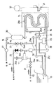
従来では、太陽熱温水器を利用する温水供給装置として、図6に示すものが公知である。この従来装置の太陽熱温水器1は、給水源からの供給された水を循環ポンプ2で循環させ、太陽光の熱を受けて受熱部3で熱交換して加熱し、これを放熱部4で放熱させることにより、蓄熱槽5内の水を加熱し、蓄熱するものである。蓄熱槽5内の蓄熱水は、蓄熱水管路6を通じて給湯装置7へ導かれ、更に吐水手段としての湯水混合水栓8へ供給されるようになっている。なお、図6において、9は減圧逆止弁である。
【0003】
ところが、この従来の太陽熱温水器を利用する温水供給装置では、蓄熱槽5から供給される温水の温度が、例えば80℃程度の高温になることがあり、危険であるのでそのままでは浴槽への自動湯張り機能を有する給湯設備として利用できないという問題があった。
【0004】
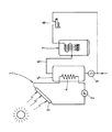
そのため、従来では、図4に示すように、蓄熱槽5からの蓄熱水管路6と、給水源からの給水管路10とを自動ミキシングバルブ11の流入口側へ接続し、前記蓄熱槽5からの高温水と給水源からの水とを混合して所定温度の温水とした上で、これを給湯装置12へ導くようにした技術が実開平5−27548号公報によって既に明らかである。給湯装置12へ供給される混合水の温度は、浴槽13への湯張り温度である例えば43℃よりも若干低い温度である例えば38℃に設定されている。
【0005】
従って、この従来の温水供給装置では、高温である蓄熱槽5からの蓄熱水を、給水源からの水と混合して一旦、38℃まで低下させており、その後で給湯装置12で再加熱して42℃の温水にしているので、これを浴槽13の自動湯張りとして利用することが可能である。つまり、蓄熱槽5からの蓄熱水を浴槽13への自動湯張りへ利用することが可能である。
【0006】
【発明が解決しようとする課題】
ところが、前記図4に示す従来の温水供給装置では、太陽熱温水器1の蓄熱槽5に貯溜された蓄熱水を浴槽13への自動湯張りのための温水として利用するために、80℃程度の高温に加熱された蓄熱槽5の蓄熱水を自動ミキシングバルブ11で水と混合して38℃程度まで低下させ、更に給湯装置12で湯水混合水栓8での使用に適した温度に再加熱している。そのため、折角、太陽熱を利用して80℃程度の高温の温水を得たにも拘らず、これをそのまま利用することができず、極めて熱効率の悪いものとなっていた。
【0007】
【課題を解決するための手段】
本発明は従来の前記課題に鑑みてこれを改良除去したものであって、太陽熱温水器等の蓄熱槽の高温水を効率良く利用することのできる温水供給装置を提供せんとするものである。
【0008】
而して、前記課題を解決するために本発明が採用した手段は、自動ミキシングバルブの水側流入口を給水源へ連通する給水管路へ接続すると共に湯側流入口を蓄熱槽の蓄熱水管路へ接続し、自動ミキシングバルブの流出口を給湯装置の熱交換部を通って湯水混合水栓等の水栓機器へ連通する給湯管路へ接続し、蓄熱槽の蓄熱水管路と自動ミキシングバルブの流出側とを連通接続してバイパス管路を設けると共に、給湯装置の流出側の給湯管路の途中と浴槽水の循環管路とを連通接続して湯張り管路を設け、前記給水管路に給水電磁弁を配設し、前記バイパス管路に給湯電磁弁を配設し、前記湯張り管路に湯張り電磁弁を配設したことを特徴とする温水供給装置である。
【0009】
要するに、この本発明の温水供給装置は、給水電磁弁と、バイパス電磁弁と、湯張り電磁弁との三つの電磁弁と、一つの自動ミキシングバルブと、給湯装置とから成り、前記三つの電磁弁を切り換えることで、浴槽への自動湯張りと、湯水混合水栓等への給湯とを行うようにしている。このように、電磁弁を切り換えるだけであり、全体の構成並びに動作を簡略化することが可能である。また蓄熱槽の高温水をそのまま利用することもでき、熱効率においても優れている。
【0010】
【発明の実施の形態】
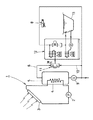
以下に、本発明の構成を図面に示す発明の実施の形態に基づいて説明すると次の通りである。なお、従来の場合と同一符号は同一部材である。図1及び図2は本発明の一実施の形態に係る温水供給装置を示すものであり、図1は自動湯張りのときの全体を示す回路図、図2は給湯のときの全体を示す回路図である。同図に示す如く、本実施の形態に係る温水供給装置にあっては、自動ミキシングバルブ11の水側流入口を給水源へ連通する給水管路10へ接続すると共に、湯側流入口を蓄熱槽(図示せず)の蓄熱水管路6へ接続している。そして、自動ミキシングバルブ11の流出口を給湯装置14の熱交換部15を通って湯水混合水栓等の水栓機器(図示せず)へ連通する給湯管路16へ接続している。
【0011】
また蓄熱槽の蓄熱水管路6と自動ミキシングバルブ11の流出側とを連通接続し、自動ミキシングバルブ11をバイパスするバイパス管路17を設けている。更に、給湯装置14の流出側の給湯管路16の途中と、浴槽水の循環管路18とを連通接続して湯張り管路19を設けている。前記浴槽水の循環管路18は、浴槽13内の浴槽水を循環ポンプ20で吸引し、給湯装置14内の熱交換部15で熱交換を行った後、浴槽13へ戻るようにした管路である。而して、自動ミキシングバルブ11の水側流入口へ連通する給水管路10には、給水電磁弁21が配設されており、自動ミキシングバルブ11をバイパスするバイパス管路17には給湯電磁弁22が配設されており、湯張り管路19には湯張り電磁弁23が配設されている。
【0012】
尚、図1及び図2において、各管路には逆流を防止するチエックバルブ24a〜24dと、温度スイッチとしてのサーミスタ25a〜25dと、流れの有無を検知するフローセンサー26と、流れを検知してスイッチング動作するフロースイッチ27と、流量を調節する流量調整弁28と、浴槽水の循環管路18において浴槽水の流れを検知するフロースイッチ29と、所望する温度に混合された温水を貯溜するミキシングタンク30とが配設されている。また給湯装置14は、バーナー31を有し、必要に応じて熱交換部15において、給湯管路16及び浴槽水の循環管路18を流れる温水を加熱するようになっている。32は送風機である。
【0013】
次に、このように構成された温水供給装置の動作態様を説明する。先ず、図1に示す浴槽13への「自動湯張り」の場合について説明する。なお、同図において、電磁弁21〜23の白抜き表示は電磁弁が開となっている状態であり、黒塗り表示は電磁弁が閉となっている状態である。この図1に示すように、自動湯張りの場合は、三つの電磁弁21〜23のうち、給水電磁弁21と湯張り電磁23とが開となっており、給湯電磁弁22は閉となっている。
【0014】
従って、自動ミキシングバルブ11の湯側流入口へは、太陽熱温水器の蓄熱槽内に貯溜されている蓄熱水がその供給管路6を通って流入し、また水側流入口へは給水源である水道水が給水管路10を通って流入する。そして、この自動ミキシングバルブ11において、給湯装置14で自動湯張りをする場合に設定が可能な最低の湯張り温度、例えば38℃にミキシングされる。ミキシングされた温水は、給湯管路16により給湯装置14の熱交換部15に案内されてここを通過し、ミキシングタンク30とフロースイッチ27との間において、給湯管路16から分岐して設けられた湯張り管路19側へ流れ、更に湯張り電磁弁23及びチエックバルブ24dを経て浴槽水の循環管路18へ流入する。そして、この浴槽水循環管路18を通って浴槽13内へ供給される。水量は、フローセンサー26によって計測され、予め設定された流量が浴槽13内へ供給された時点で給水電磁弁21及び湯張り電磁弁23を閉状態へ切り換えることによって自動湯張りを停止する。
【0015】
次に、「給湯」の場合を説明する。この場合は、給水電磁弁21と湯張り電磁弁23とを閉にし、給湯電磁弁22のみを開にする。これにより、太陽熱温水器の蓄熱槽内に貯溜されている蓄熱水がその供給管路6からバイパス管路17側へ流れ、給湯電磁弁22及びチエックバルブ24cを経て給湯管路16へ流入する。そして、給湯装置14内の熱交換部15を通過し、更にフロースイッチ27を通って湯水混合水栓等の水栓機器(図示せず)から吐出される。
【0016】
このとき、太陽熱温水器の蓄熱槽内に貯溜されている蓄熱水の温度が、水栓機器で使用しようとする温水の設定温度よりも低い場合は、給湯装置14のバーナー31を点火させ、送風機32を駆動させて熱交換部15を通過するときに温風加熱により、設定温度又はそれ以上の高温になるように加熱している。また蓄熱水の温度が水栓機器で使用しようとする温水の設定温度よりも高い場合は、バーナー31及び送風機32は停止したままであり、高温の蓄熱水がそのまま水栓機器へ供給されて吐出されるようになっている。つまり、太陽熱温水器の蓄熱槽内に貯溜されている蓄熱水が高温の場合は、そのままこれを利用して水栓機器から給湯することが可能である。
【0017】
なお、本発明は前述した実施の形態に限定されるものではなく、適宜の変更が可能である。例えば、蓄熱槽の蓄熱水は、太陽熱温水器の太陽光熱を利用したものに限らず、各種産業における廃熱を利用するものであってもよい。
【0018】
【発明の効果】
以上説明したように本発明にあっては、太陽熱温水器等の蓄熱槽の蓄熱水と水道水等の給水とを自動ミキシングバルブでミキシングし、これを給湯装置の熱交換部を経て浴槽水の循環管路へ供給し、浴槽への自動湯張りを行うようにしている。また前記蓄熱水を自動ミキシングバルブをバイパスさせ、給湯装置の熱交換部を経て水栓機器へ直接に供給するようにしている。しかも、これらの流路の切り換えを三つの電磁弁を開閉制御するだけで行っている。
【0019】
従って、温水供給装置の全体の回路構成並びにその制御を極めて簡略化することが可能であり、また蓄熱槽内に貯溜された高温の蓄熱水をそのまま利用することもでき、従来のように高温の蓄熱水の温度を一旦低下させて、更に再加熱してその温度を上げる等の必要がなく、熱効率においても優れている。
【図面の簡単な説明】
【図1】本発明の一実施の形態に係るものであり、自動湯張りの場合の全体の配管回路を示す図面である。
【図2】本発明の一実施の形態に係るものであり、給湯の場合の全体の配管回路を示す図面である。
【図3】従来の温水供給装置の一例を示す全体の配管回路を示す図面である。
【図4】従来の温水供給装置の別の例を示す全体の配管回路を示す図面である。
【符号の説明】
1…太陽熱温水器
3…受熱部
4…放熱部
5…蓄熱槽
6…蓄熱水管路
8…湯水混合水栓
10…給水管路
11…自動ミキシングバルブ
13…浴槽
14…給湯装置
15…熱交換部
16…給湯管路
17…バイパス管路
18…浴槽水の循環管路
19…湯張り管路
21…給水電磁弁
22…給湯電磁弁
23…湯張り電磁弁[0001]
TECHNICAL FIELD OF THE INVENTION
The present invention relates to a hot water supply device in which heat storage water obtained by a solar water heater or a waste heat recovery device is used as a hot water supply source of a faucet device such as a hot water mixing faucet or an automatic hot water filling device for a bathtub. is there.
[0002]
[Prior art]
Conventionally, a hot water supply device using a solar water heater as shown in FIG. 6 is known. The solar water heater 1 of this conventional device circulates water supplied from a water supply source by a circulation pump 2, receives heat of sunlight, exchanges heat in a heat receiving unit 3, and heats the heat. By radiating heat, the water in the heat storage tank 5 is heated and stored. The heat storage water in the heat storage tank 5 is guided to a hot water supply device 7 through a heat storage water pipe 6 and further supplied to a hot / water mixing faucet 8 as a water discharging means. In FIG. 6, reference numeral 9 denotes a pressure reducing check valve.
[0003]
However, in this conventional hot water supply device using a solar water heater, the temperature of the hot water supplied from the heat storage tank 5 may be as high as, for example, about 80 ° C., and it is dangerous. There is a problem that it cannot be used as hot water supply equipment having a hot water filling function.
[0004]
Therefore, conventionally, as shown in FIG. 4, the heat storage water pipe 6 from the heat storage tank 5 and the water supply pipe 10 from the water supply source are connected to the inlet side of the automatic mixing valve 11. Japanese Patent Application Laid-Open No. Hei 5-27548 discloses a technique in which high-temperature water and water from a water supply source are mixed to obtain hot water having a predetermined temperature, and the hot water is guided to the hot water supply device 12. The temperature of the mixed water supplied to the hot water supply device 12 is set to, for example, 38 ° C., which is slightly lower than the bathing temperature of the bathtub 13, for example, 43 ° C.
[0005]
Therefore, in this conventional hot water supply device, the heat storage water from the heat storage tank 5 which is high in temperature is mixed with the water from the water supply source to temporarily lower the temperature to 38 ° C., and then reheated by the hot water supply device 12. Since the hot water is heated to 42 ° C., it can be used as an automatic filling of the bathtub 13. That is, the heat storage water from the heat storage tank 5 can be used for automatic hot water filling in the bathtub 13.
[0006]
[Problems to be solved by the invention]
However, in the conventional hot water supply device shown in FIG. 4, the temperature of about 80 ° C. is used in order to use the heat storage water stored in the heat storage tank 5 of the solar water heater 1 as hot water for automatic hot water filling in the bathtub 13. The heat storage water in the heat storage tank 5 heated to a high temperature is mixed with water by the automatic mixing valve 11 to lower the temperature to about 38 ° C., and further reheated by the hot water supply device 12 to a temperature suitable for use in the hot water mixing faucet 8. ing. For this reason, despite the fact that hot water of about 80 ° C. was obtained using solar heat, it could not be used as it was, resulting in extremely poor thermal efficiency.
[0007]
[Means for Solving the Problems]
The present invention has been made in view of the above-mentioned problems and has been improved and eliminated, and it is an object of the present invention to provide a hot water supply device that can efficiently use high-temperature water in a heat storage tank such as a solar water heater.
[0008]
Means adopted by the present invention to solve the above problems is to connect the water-side inlet of the automatic mixing valve to a water supply pipe communicating with a water supply source and connect the hot-side inlet to a heat storage water pipe of a heat storage tank. And the outlet of the automatic mixing valve is connected to the hot water supply line that communicates with the faucet equipment such as the hot and cold water mixing faucet through the heat exchange section of the hot water supply device, and the heat storage water line of the heat storage tank and the automatic mixing valve are connected. The hot water supply line is connected to the outflow side of the hot water supply device, and the hot water supply line is connected to the middle of the hot water supply line on the outflow side of the hot water supply device and the circulation line of the bathtub water. A hot water supply apparatus, comprising: a water supply electromagnetic valve disposed in a path; a hot water supply electromagnetic valve disposed in the bypass conduit; and a hot water electromagnetic valve disposed in the hot water conduit.
[0009]
In short, the hot water supply device of the present invention comprises three electromagnetic valves, namely, a water supply electromagnetic valve, a bypass electromagnetic valve, and a hot water filling electromagnetic valve, one automatic mixing valve, and a hot water supply device. By switching the valve, automatic hot water filling to the bathtub and hot water supply to the hot water mixing faucet and the like are performed. In this way, only by switching the solenoid valve, it is possible to simplify the entire configuration and operation. Also, the high-temperature water in the heat storage tank can be used as it is, and the thermal efficiency is excellent.
[0010]
BEST MODE FOR CARRYING OUT THE INVENTION
Hereinafter, the configuration of the present invention will be described based on an embodiment of the invention shown in the drawings. The same reference numerals as those in the conventional case denote the same members. FIGS. 1 and 2 show a hot water supply apparatus according to an embodiment of the present invention. FIG. 1 is a circuit diagram showing an entire hot water filling system, and FIG. 2 is a circuit diagram showing an entire hot water supply. FIG. As shown in the figure, in the hot water supply device according to the present embodiment, the water-side inlet of the automatic mixing valve 11 is connected to the water supply line 10 communicating with the water supply source, and the hot-side inlet is stored in the hot water inlet. It is connected to a heat storage water pipe 6 of a tank (not shown). The outlet of the automatic mixing valve 11 is connected to a hot water supply pipe line 16 communicating with a faucet device (not shown) such as a hot and cold water mixing faucet through a heat exchange unit 15 of the hot water supply device 14.
[0011]
Further, a bypass pipe line 17 that connects the heat storage water pipe line 6 of the heat storage tank and the outflow side of the automatic mixing valve 11 and bypasses the automatic mixing valve 11 is provided. Further, a hot water supply line 19 is provided by connecting a middle part of the hot water supply line 16 on the outflow side of the hot water supply device 14 and a circulation line 18 of the bathtub water. The tub water circulation line 18 is a line in which the tub water in the tub 13 is sucked by the circulating pump 20, heat is exchanged in the heat exchange unit 15 in the hot water supply device 14, and then returned to the tub 13. It is. A water supply solenoid valve 21 is provided in the water supply pipe 10 communicating with the water-side inlet of the automatic mixing valve 11, and a hot water supply solenoid valve is provided in a bypass pipe 17 that bypasses the automatic mixing valve 11. 22 is provided, and in the filling line 19, a filling electromagnetic valve 23 is provided.
[0012]
In FIGS. 1 and 2, check valves 24a to 24d for preventing backflow, thermistors 25a to 25d as temperature switches, a flow sensor 26 for detecting the presence or absence of flow, and a flow for detecting flow Switch 27 for controlling the flow rate, a flow control valve 28 for adjusting the flow rate, a flow switch 29 for detecting the flow of bathtub water in the bathtub circulation line 18, and storing hot water mixed to a desired temperature. A mixing tank 30 is provided. The hot water supply device 14 has a burner 31 and heats hot water flowing through the hot water supply line 16 and the bathtub water circulation line 18 in the heat exchange unit 15 as necessary. 32 is a blower.
[0013]
Next, an operation mode of the hot water supply device configured as described above will be described. First, the case of “automatic hot water filling” of the bathtub 13 shown in FIG. 1 will be described. Note that, in the same figure, the white display of the solenoid valves 21 to 23 is a state where the solenoid valves are open, and the black display is a state where the solenoid valves are closed. As shown in FIG. 1, in the case of automatic hot water filling, of the three solenoid valves 21 to 23, the water supply electromagnetic valve 21 and the hot water electromagnetic 23 are open, and the hot water supply electromagnetic valve 22 is closed. ing.
[0014]
Therefore, the heat storage water stored in the heat storage tank of the solar water heater flows into the hot water inlet of the automatic mixing valve 11 through the supply pipe 6, and the water inlet is supplied by a water supply source. Some tap water flows in through the water supply line 10. Then, in the automatic mixing valve 11, mixing is performed to a minimum filling temperature, for example, 38 ° C., which can be set when automatic filling is performed by the hot water supply device 14. The mixed hot water is guided by the hot water supply line 16 to the heat exchange unit 15 of the hot water supply device 14 and passes therethrough, and is provided between the mixing tank 30 and the flow switch 27 so as to branch off from the hot water supply line 16. It flows to the hot water filling line 19 and further flows into the bathtub water circulation line 18 via the hot water filling solenoid valve 23 and the check valve 24d. Then, the water is supplied into the bathtub 13 through the bathtub water circulation line 18. The water amount is measured by the flow sensor 26, and when the preset flow rate is supplied into the bathtub 13, the automatic water filling is stopped by switching the water supply electromagnetic valve 21 and the hot water filling electromagnetic valve 23 to the closed state.
[0015]
Next, the case of "hot water supply" will be described. In this case, the water supply electromagnetic valve 21 and the hot water filling electromagnetic valve 23 are closed, and only the hot water supply electromagnetic valve 22 is opened. Thereby, the heat storage water stored in the heat storage tank of the solar water heater flows from the supply pipe 6 to the bypass pipe 17 side, and flows into the hot water supply pipe 16 via the hot water supply electromagnetic valve 22 and the check valve 24c. Then, the water passes through the heat exchange unit 15 in the hot water supply device 14 and further passes through the flow switch 27 and is discharged from a faucet device (not shown) such as a hot water mixing faucet.
[0016]
At this time, when the temperature of the heat storage water stored in the heat storage tank of the solar water heater is lower than the set temperature of the hot water to be used in the faucet device, the burner 31 of the water heater 14 is ignited, and the blower When driving the heat exchanger 32 and passing it through the heat exchanging section 15, the air is heated to a set temperature or higher by hot air heating. When the temperature of the heat storage water is higher than the set temperature of the hot water to be used in the faucet device, the burner 31 and the blower 32 remain stopped, and the high-temperature heat storage water is directly supplied to the faucet device and discharged. It is supposed to be. In other words, when the heat storage water stored in the heat storage tank of the solar water heater is at a high temperature, hot water can be supplied from the faucet device by using the hot water.
[0017]
It should be noted that the present invention is not limited to the above-described embodiment, and appropriate changes can be made. For example, the heat storage water in the heat storage tank is not limited to the one using the solar heat of the solar water heater, and may use the waste heat in various industries.
[0018]
【The invention's effect】
As described above, in the present invention, the heat storage water of a heat storage tank such as a solar water heater and the water supply such as tap water are mixed by an automatic mixing valve, and the water is supplied to a bath water through a heat exchange unit of a water heater. The water is supplied to the circulation pipe and the bath is automatically filled with water. Further, the heat storage water is bypassed through the automatic mixing valve, and is supplied directly to the faucet equipment via the heat exchange unit of the hot water supply device. In addition, the switching of these flow paths is performed only by controlling the opening and closing of the three solenoid valves.
[0019]
Therefore, the entire circuit configuration of the hot water supply device and its control can be extremely simplified, and the high-temperature heat storage water stored in the heat storage tank can be used as it is, and the high-temperature heat storage There is no need to lower the temperature of the heat storage water once and then reheat it to raise the temperature, and the heat efficiency is excellent.
[Brief description of the drawings]
FIG. 1 is a drawing according to one embodiment of the present invention, showing an entire piping circuit in the case of automatic filling.
FIG. 2 relates to one embodiment of the present invention, and is a drawing showing an entire piping circuit in the case of hot water supply.
FIG. 3 is a drawing showing an entire piping circuit showing an example of a conventional hot water supply device.
FIG. 4 is a drawing showing an entire piping circuit showing another example of a conventional hot water supply device.
[Explanation of symbols]
DESCRIPTION OF SYMBOLS 1 ... Solar water heater 3 ... Heat receiving part 4 ... Heat radiating part 5 ... Heat storage tank 6 ... Heat storage water pipe 8 ... Hot water mixing faucet 10 ... Water supply pipe 11 ... Automatic mixing valve 13 ... Bath tub 14 ... Hot water supply apparatus 15 ... Heat exchange part 16 hot water supply line 17 bypass line 18 bath water circulation line 19 hot water supply line 21 water supply solenoid valve 22 hot water supply solenoid valve 23 hot water supply solenoid valve