JP3553774B2 - Cartridge eject device - Google Patents
Cartridge eject device Download PDFInfo
- Publication number
- JP3553774B2 JP3553774B2 JP29762197A JP29762197A JP3553774B2 JP 3553774 B2 JP3553774 B2 JP 3553774B2 JP 29762197 A JP29762197 A JP 29762197A JP 29762197 A JP29762197 A JP 29762197A JP 3553774 B2 JP3553774 B2 JP 3553774B2
- Authority
- JP
- Japan
- Prior art keywords
- cartridge
- piece
- unlocking
- cartridge holder
- lock
- Prior art date
- Legal status (The legal status is an assumption and is not a legal conclusion. Google has not performed a legal analysis and makes no representation as to the accuracy of the status listed.)
- Expired - Fee Related
Links
Images


Description
【0001】
【発明の属する技術分野】
本発明は携帯用ディスク装置などに使用されるカートリッジイジェクト装置に関するものである。
【0002】
【従来の技術】
光ディスク媒体を光ピックアップで読み取って再生する携帯用ディスク装置としては、カートリッジに64mmの光ディスク媒体を内蔵したミニディスク(大きさは72mm×68mm×5mm)に記録された音楽を手軽にアウトドアに持ち出して聴けるように、軽量小型化された携帯用MDプレーヤーが一般に普及している。
【0003】
携帯用MDプレーヤーでは、外装ケースの上蓋を開くとカートリッジホルダーのカートリッジ挿入口が現れ、カートリッジホルダーにカートリッジを挿入すると、この挿入の操作に連動してカートリッジのシャッタが開放される。
【0004】
このようにカートリッジをカートリッジホルダーにセットして前記の上蓋を閉じると、カートリッジに収容されている光ディスクが、ドライブ装置に結合され、シャッタが開放されたカートリッジの開口から光ヘッドが光ディスクにアクセスできる状態になる。
【0005】
カートリッジの交換の際には、上蓋を開くことによって、それまでカートリッジホルダーにセットされていたカートリッジがイジェクト可能な状態に飛び出すように、従来ではカートリッジイジェクト装置が設けられている。
【0006】
この従来のカートリッジイジェクト装置の一例としては、特開平7−85560号公報に開示されたものがある。これは図29に示すように、シャーシ41の軸支部46に一端が回動自在に枢支されるカートリッジホルダー47に、シャッター開閉部材48と、イジェクトレバー58と、ロック部材67などを組み付け、シャーシ41にはラチェット部材72を組み付けて構成されている。69はロック部材67を付勢するコイルバネ、74はラチェット部材72を付勢するコイルバネである。
【0007】
【発明が解決しようとする課題】
しかしながら、図29に示す従来の構成では、ロック部材67とラチェット部材72が必要であって部品点数が多く、さらに、ロック部材67とラチェット部材72を組み付けた状態の両者間の組み上げ精度が、イジェクト動作に影響し、確実な動作を得るためには高精度の部品加工と組み立てが要求されるものである。
【0008】
本発明は、部品点数の削減と組み立て工数の低減を達成できるカートリッジイジェクト装置を提供することを目的とする。
【0009】
【課題を解決するための手段】
本発明のカートリッジイジェクト装置は、カートリッジホルダーに摺動自在に取り付けられるイジェクトスライダに、弾性変形が可能なロック片およびロック解除用係合片を一体に形成したことを特徴とする。
【0010】
また、本発明のカートリッジイジェクト装置は、カートリッジホルダーに摺動自在に取り付けられカートリッジホルダーの係止部材に係合するロック片を有するイジェクトスライダと、記録再生装置の外装ケースの側に設けられて前記ロック片のロック解除に寄与するロック解除手段を設け、カートリッジホルダーを閉じるときには互いの当接によって前記ロック片とロック解除手段の少なくとも一方を弾性変形ができるように構成して、カートリッジホルダーを開けるときには、ロック解除手段がカートリッジホルダーの係止部材とロック片との係合を解除するように構成したことを特徴とする。
【0011】
この本発明によると、部品点数の削減と組み立て工数の低減を達成できるカートリッジイジェクト装置を実現できる。
【0012】
【発明の実施の形態】
請求項1記載のカートリッジイジェクト装置は、記録再生装置の外装ケースの蓋体の開閉動作に連動して回動自在に支持されカートリッジが挿入保持されるカートリッジホルダーと、前記カートリッジホルダーに摺動自在に取り付けられるとともに挿入されたカートリッジに係合するカートリッジ係合片を有するイジェクトスライダと、前記イジェクトスライダに一体に形成され弾性変形が可能なロック片およびロック片解除用係合片を有するロック手段と、前記イジェクトスライダをカートリッジのイジェクト方向に付勢するイジェクト付勢手段と、前記カートリッジホルダーに設けられ前記ロック手段のロック片をロックする係止部材と、前記カートリッジホルダーを回動自在に支持する記録再生装置の本体側に設けられ前記ロック手段のロック解除用係合片と係合してロック片の係止部に対するロックを解除するロック解除部材を備え、前記ロック手段は、蓋体が開状態でカートリッジをカートリッジホルダーに奥部まで挿入した際にロック片が係止部材にロックされるとともに、前記蓋体の閉状態から開く際にロック解除用係合片がロック解除部材に係合してロック状態が解除され、カートリッジをカートリッジホルダーからイジェクトすることを特徴とする。
【0013】
請求項2記載のカートリッジイジェクト装置は、請求項1において、イジェクトスライダとロック手段を1枚の板金により構成し、カートリッジ係合片をカートリッジホルダーのカートリッジ挿入域に突出形成し、カートリッジの挿入押圧によりイジェクトスライダを摺動するとともに、ロック手段をロックするように構成したことを特徴とする。
【0014】
請求項3記載のカートリッジイジェクト装置は、請求項1または請求項2において、ロック手段のロック解除用係合片は、蓋体の開状態から閉状態に回動するカートリッジホルダーの回動の際、ロック解除部材と係合するも、当該ロック解除用係合片とロック解除部材のうちの少なくとも一方の弾性変形によりロック片のロック状態を解除することなく蓋が閉状態となるように構成したことを特徴とする。
【0015】
請求項4記載のカートリッジイジェクト装置は、請求項1または請求項2において、ロック解除部材は、カートリッジホルダーを回動自在に保持するシャーシを折り曲げて一体に形成したことを特徴とする。
【0016】
請求項5記載のカートリッジイジェクト装置は、請求項1または請求項2において、ロック解除部材は、カートリッジホルダーを回動自在に保持するシャーシに保持した弾性部材で形成し、ロック解除用係合片の蓋の閉方向への移動時には変形し、蓋の開方向への移動時にはロック解除用係合片と係合可能に構成したことを特徴とする。
【0017】
以下、本発明のカートリッジイジェクト装置を各実施の形態に基づいて説明する。
(実施の形態1)
図1〜図15は本発明のカートリッジイジェクト装置を備えた携帯用ディスク装置を示す。
【0018】
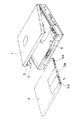
図1に示すように、携帯用MDプレーヤーの外装ケースの上蓋1を開くとカートリッジホルダー2のカートリッジ挿入口3が現れ、カートリッジホルダー2にカートリッジ4を挿入すると、この挿入の操作に連動してカートリッジ4のシャッタ5が開放される。6はメカシャーシである。
【0019】
カートリッジホルダー2は、図2に示すように後端の両側に形成された折曲部7に穿設された孔8に、メカシャーシ6の後端に形成された軸支片9を挿入して回動自在に支持されている。カートリッジホルダー2には、前記の折曲部7の他にも支持板部10と係止部材11とシャッター開放部材12aとシャッター閉塞部材12bと一対の切り起こし片13a,13bなどが一体に板金加工で形成されている。メカシャーシ6にはロック解除部材14が一体に板金加工で形成されている。
【0020】
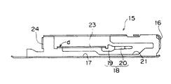
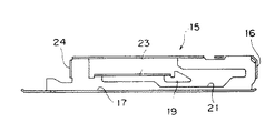
カートリッジホルダー2に組み付けられるイジェクトスライダ15は、図3と図4に示すようにカートリッジホルダー2に挿入されたカートリッジ4に当接する係合片16と、カートリッジホルダー2の前記の支持板部10に沿うベース部17と、ロック手段18とが板金加工で一体に形成されている。
【0021】
このロック手段18は、ロック片19とこのロック片19の先端に形成されたロック解除用係合片20とが、孔21を穿設する板金加工でイジェクトスライダ15に一体に形成されている。
【0022】
なお、ベース部17にはカートリッジホルダー2の支持板部10の切り起こし片13a,13bが係合するガイド長孔22a,22bが形成されている。ロック片19には、図4に示すように長手方向(矢印A方向)の剛性を満足させるために折曲辺23が一体に形成されている。ロック解除用係合片20は中間部を外側(矢印B方向)に突出させるようにへの字状に成形して、このロック解除用係合片20の先端20aは内側(矢印C方向)に向いている。
【0023】
イジェクトスライダ15はカートリッジホルダー2に図5に示すように、カートリッジホルダー2の切り起こし片13a,13bをイジェクトスライダ15のガイド長孔22a,22bに係合させてスライド自在に組み付け、イジェクトスライダ15に一体に形成されているバネ係止片24とカートリッジホルダー2に一体に形成されているバネ係止片25の間に引っ張りコイルバネ26が介装されている。
【0024】
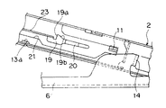
図5と図6は上蓋1を開いてカートリッジ挿入口3からカートリッジ4をイジェクトスライダ15の係合片16に当接するまで挿入した状態を示している。この状態から引っ張りコイルバネ26の付勢に抗してカートリッジ4を押し込むと、この状態では、カートリッジ4の溝4aにシャッター開放部材12aが係合して、またシャッタ5の孔5aにシャッター閉塞部材12bが係合した状態でシャッタ5が溝4bに沿って解放され、カートリッジホルダー2に対してイジェクトスライダ15はガイド長孔22a,22bに沿って摺動し、イジェクトスライダ15のロック片19の係止部19aがカートリッジホルダー2の係止部材11に係合する直前位置で、図7に示すようにイジェクトスライダ15のロック解除用係合片20の先端がメカシャーシ6のロック解除部材14の側面に当接するとともに、ロック片19の係止部19aの直前に形成されている傾斜面19bがカートリッジホルダー2の係止部材14の裏面に当接する。
【0025】
なお、ロック解除用係合片20の先端がメカシャーシ6のロック解除部材14の側面に当接した状態におけるロック解除用係合片20の先端を逃がす孔2aが、カートリッジホルダー2の側に設けられている。
【0026】
カートリッジ4がさらに押し込まれることによってロック片19がカートリッジホルダー2の係止部材11によって押し下げられて、ロック片19は基端部dを支点に先端が下方に弾性変形し、ロック片19の傾斜面19bがカートリッジホルダー2の係止部材14を通過した時に前記の弾性変形が解除されて、図8と図9に示すようにイジェクトスライダ15のロック片19の係止部19aがカートリッジホルダー2の係止部材11に係合して、カートリッジホルダー2におけるイジェクトスライダ15の摺動位置がロックされる。このイジェクトスライダ15がロックされた状態では、カートリッジ4を押し込む操作力を解除してもカートリッジ4はカートリッジホルダー2から飛び出さない。また、この図8に示す状態では、イジェクトスライダ15のロック解除用係合片20の先端がメカシャーシ6のロック解除部材14の側面に当接している。
【0027】
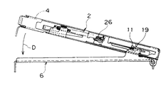
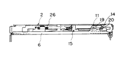
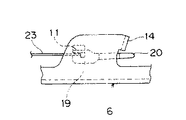
次に、上蓋1を閉じる方向に回動させると、カートリッジホルダー2が図8の矢印D方向に回動し、メカシャーシ6のロック解除部材14の側面に当接していたロック解除用係合片20が図10〜図12に示すようにロック解除部材14の側面から外れて、ロック解除用係合片20がロック解除部材14の下方位置に移動する。この図10〜図12に示す状態でカートリッジ1に収容された光ディスクの記録再生が実施される。
【0028】
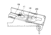
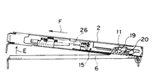
カートリッジ4の交換の際には、上蓋1を開くことによって、カートリッジホルダー2が図13に示すように矢印E方向に回動する。この回動の際には、図14に示すようにイジェクトスライダ15のロック解除用係合片20の中間部がメカシャーシ6のロック解除部材14によって押し下げられて、イジェクトスライダ15のロック片19の係止部19aとカートリッジホルダー2の係止部材11との係合が解除されて、イジェクトスライダ15が引っ張りコイルバネ26の付勢力でカートリッジホルダー2に対して矢印F方向に摺動する。この際に、イジェクトスライダ15の係合片16によってカートリッジ4が図15に示すようにカートリッジホルダー2から押し出されてイジェクトが実行される。
【0029】
このように、イジェクトスライダ15のロック片19に一体にロック解除用係合片20を設け、カートリッジホルダー2に一体に形成された係止部材11に係合してロックされたイジェクトスライダ15の前記ロックを解除する際には、上蓋1の開放操作に連動してカートリッジホルダー2が回動するが、イジェクトスライダ15のロック解除用係合片20の回動がメカシャーシ6に一体に設けたロック解除部材14によって規制されて、前記のロック片19と係止部材11とが係合したロック状態が解除されてイジェクトが実行されるので、図29に示した従来例のロック部材67やラチェット部材72などを必要とせず、その組み付け工程を必要としない。
【0030】
(実施の形態2)
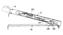
図16〜図29は本発明の(実施の形態2)のカートリッジイジェクト装置を備えた携帯用ディスク装置を示す。なお、(実施の形態1)と同様の作用をなすものには同一の符号を付けて説明する。
【0031】
(実施の形態1)ではロック手段18がロック片19とロック解除用係合片20とで構成され、外装ケースの上蓋1を開く際には、メカシャーシ6の側のロック解除部材14にイジェクトスライダ15の側のロック解除用係合片20が係合して、上蓋1を開く動作に連動してカートリッジホルダー2が開状態に回動することによってロック片19がカートリッジホルダー2の側の係止部材11から外れてカートリッジ4のイジェクトが実行されたが、この(実施の形態2)では、(実施の形態1)におけるロック解除用係合片20に相当する構成要件がイジェクトスライダ15の側には設けられておらず、その代わりにメカシャーシ6の側のロック解除部材14が弾性変形できるように構成されている。
【0032】
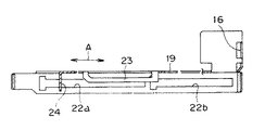
図16に示すカートリッジホルダー2は(実施の形態1)と同様で、イジェクトスライダ15の要部の形状が図17と図18に示すように構成されている。
イジェクトスライダ15には、カートリッジホルダー2に挿入されたカートリッジ4に当接する係合片16と、カートリッジホルダー2の支持板部10に沿うベース部17と、孔21を穿設して形成されたロック片19とが板金加工で一体に形成されている。
【0033】
なお、ベース部17にはカートリッジホルダー2の切り起こし片13a,13bが係合するガイド長孔22a,22bが形成されている。ロック片19には、図18に示すように長手方向(矢印A方向)の剛性を満足させるために折曲辺23が一体に形成されている。
【0034】
イジェクトスライダ15はカートリッジホルダー2に図19に示すように、カートリッジホルダー2の切り起こし片13a,13bをイジェクトスライダ15のガイド長孔22a,22bに係合させてスライド自在に組み付け、イジェクトスライダ15に一体に形成されているバネ係止片24とカートリッジホルダー2に一体に形成されているバネ係止片25の間に引っ張りコイルバネ26が介装されている。
【0035】
図16に示すメカシャーシ6の側に設けられた係止部材27は、メカシャーシ6に形成されたロック解除部本体28と、このロック解除部本体28に取り付けられるロック解除片29とで構成されている。この詳細は図24に示すように形成されている。
【0036】
図24の(a)(c)に示すように、バネ材を板金加工で形成されたロック解除片29には、メカシャーシ6のロック解除部本体28の後端に形成された第1の凸部28aに係合する孔29aが穿設された第1の折曲片29bがロック解除片本体29cの後部に形成され、ロック解除片本体29cの前端の上面にはカートリッジホルダー2に近付くように内側に折り曲げられた第2の折曲片29dが形成されている。第2の折曲片29dの途中には、後端に向かって延びる支持片29eが形成され、さらに、ロック解除片本体29cには、メカシャーシ6のロック解除部本体28の外側面に形成された第2の凸部28bに係合する切欠部29fが形成されている。
【0037】
さらに、このロック解除片29の前記の切欠部29fを形成することによってロック解除片本体29cに形成された腕部29gは、矢印G方向に内側に僅かに折り曲げて形成されている。
【0038】
このように構成されたロック解除片29のメカシャーシ6のロック解除部本体28への取り付けは、図24の(b)から(c)に示すようにワンタッチ操作で簡単に取り付けられる。
【0039】
具体的には、図24の(b)に示すように、ロック解除片29の第1の折曲片29bをメカシャーシ6のロック解除部本体28の第1の凸部28aに僅かだけ係合させるとともに、ロック解除片29の支持片29eとロック解除片本体29cの内側とでメカシャーシ6のロック解除部本体28の上部凸部28cを挟持し、メカシャーシ6のロック解除部本体28の上にロック解除片29が前上がりになった状態で載置される。この状態でロック解除片29の前端部を矢印Hで示すように下方に押圧すると、ロック解除片29は第1の折曲片29bの孔29aとメカシャーシ6のロック解除部本体28の第1の凸部28aとの係合箇所(ポイントP1)を中心に回動して図24(c)に示すようにロック解除片29の腕部29gがメカシャーシ6のロック解除部本体28の第2の凸部28bを乗り越えて、ロック解除片29の切欠部29fに第2の凸部28dが入り込んだ目的位置にセットされる。
【0040】
この図24(c)に示すセット状態では、メカシャーシ6のロック解除部本体28におけるロック解除片29の前後方向(矢印J方向)の位置は、メカシャーシ6のロック解除部本体28の後端面とロック解除片29の第1の折曲片29bとの当接(ポイントP2)と、メカシャーシ6のロック解除部本体28の上部凸部28cの前端とロック解除片29の第2の折曲片29dとの当接(ポイントP3)とで規制されて位置決めされている。
【0041】
また、上下方向の位置は、ロック解除片29の腕部29gがメカシャーシ6の第2の凸部28bに係合することによって位置決めされている。
また、左右方向の位置は、ロック解除片29の第2のロック解除片29の支持片29eの係止片本体側の端面29hを、メカシャーシ6の上部凸部28cの内周面に、ロック解除片29の腕部29gの弾性力で押し付けて位置決めされている。
【0042】
このようにメカシャーシ6のロック解除部本体28にセットされたロック解除片29の第2の折曲片29dの先端部29iが、下記に示すようにカートリッジのイジェクト動作に重要な役割を果たす。
【0043】
図19は上蓋1を開いてカートリッジ挿入口3からカートリッジ4を挿入している状態を示している。このときのイジェクトスライダ15のロック片19とメカシャーシ6の側のロック解除片29との位置関係を図20に示す。
【0044】
カートリッジ4をイジェクトスライダ15の係合片16に当接するまで挿入していくと、イジェクトスライダ15が引っ張りコイルバネ26の付勢に抗してカートリッジホルダー2に対してイジェクトスライダ15がガイド長孔22a,22bに沿って摺動し、図21に示すようにイジェクトスライダ15のロック片19の係止部19aがカートリッジホルダー2の係止部材11に係合する直前位置で、ロック片19の係止部19aの直前に形成されている傾斜面19bがカートリッジホルダー2の係止部材11の裏面に当接する。
【0045】
カートリッジ4がさらに押し込まれることによってロック片19がカートリッジホルダー2の係止部材11によって押し下げられて、ロック片19は基端部dを支点に先端が下方に弾性変形し、ロック片19の傾斜面19bがカートリッジホルダー2の係止部材11を通過した時に前記の弾性変形が解除されて、図22と図23に示すようにイジェクトスライダ15のロック片19の係止部19aがカートリッジホルダー2の係止部材11に係合して、カートリッジホルダー2におけるイジェクトスライダ15の摺動位置がロックされる。このイジェクトスライダ15がロックされた状態では、カートリッジ4を押し込む操作力を解除してもカートリッジ4はカートリッジホルダー2から飛び出さない。
【0046】
この状態におけるイジェクトスライダ15のロック片19とメカシャーシ6の側のロック解除片29との位置関係を図25に示す。図26の(a)は図25のX−X′矢視図を示す。この図からも分かるように、イジェクトスライダ15の折曲辺23の奥端23aはロック解除片29の第2の折曲片29dの先端部29iよりも上方に位置している。
【0047】
次に、上蓋1を閉じる方向に回動させると、カートリッジホルダー2が図22の矢印D方向に回動し、その途中でイジェクトスライダ15の折曲辺23の奥端23aとロック解除片29の第2の折曲片29dの先端部29iとが当接して、図26の(b)に示すようにロック解除片29の第2の折曲片29dの先端部29iが下方に弾性変形し、イジェクトスライダ15の折曲辺23が図26の(c)および図27に示すようにロック解除片29の第2の折曲片29dの側方を下側に向かって通過する。
【0048】
カートリッジ4の交換の際には、上蓋1を開くことによって、カートリッジホルダー2が図28に示すように矢印E方向に回動する。この回動の際には、イジェクトスライダ15の折曲辺23がメカシャーシ6の側の第2の折曲片29dの先端部29iの下方に当接して押し下げられて、イジェクトスライダ15のロック片19の係止部19aとカートリッジホルダー2の係止部材11との係合が解除されて、イジェクトスライダ15が引っ張りコイルバネ26の付勢力でカートリッジホルダー2に対して矢印F方向に摺動する。この際に、イジェクトスライダ15の係合片16によってカートリッジ4が図28に示すようにカートリッジホルダー2から押し出される。
【0049】
上記の(実施の形態2)では、第2の折曲片29dとロック片19のうちの第2の折曲片29dを弾性変形するように構成したが、ロック片19の方を弾性変形するように構成したり、第2の折曲片29dとロック片19の両方をを弾性変形するようにして構成することもできる。
【0050】
【発明の効果】
以上のように本発明によると、カートリッジホルダーに摺動自在に取り付けられるイジェクトスライダに、弾性変形が可能なロック片およびロック解除用係合片を一体に形成したため、部品点数の削減と組み立て工数の低減を達成してカートリッジのイジェクトを実現できる。
【0051】
また、本発明によると、カートリッジホルダーに摺動自在に取り付けられカートリッジホルダーの係止部材に係合するロック片を有するイジェクトスライダと、記録再生装置の外装ケースの側に設けられて前記ロック片のロック解除に寄与するロック解除手段を設け、カートリッジホルダーを閉じるときには互いの当接によって前記ロック片とロック解除手段の少なくとも一方を弾性変形ができるように構成して、カートリッジホルダーを開けるときには、ロック解除手段がカートリッジホルダーの係止部材とロック片との係合を解除するように構成したため、部品点数の削減と組み立て工数の低減を達成してカートリッジのイジェクトを実現できる。
【図面の簡単な説明】
【図1】本発明のカートリッジイジェクト装置を備えた携帯用ディスク装置の外観斜視図
【図2】同(実施の形態1)のカートリッジイジェクト装置の分解斜視図
【図3】同実施の形態のイジェクトスライダの正面図
【図4】図3の一部切欠き平面図
【図5】同実施の形態の上蓋を開いた状態のカートリッジイジェクト装置の正面図
【図6】図5の要部の拡大図
【図7】図5の状態でカートリッジを終端の近くまで押し込んだ状態の要部の平面図
【図8】図5の状態でカートリッジを終端まで押し込んだ状態の正面図
【図9】図8の要部の拡大図
【図10】同実施の形態の上蓋を閉じた状態のカートリッジイジェクト装置の正面図
【図11】図10の要部の拡大図
【図12】図10の状態の要部の平面図
【図13】上蓋を閉じた状態から開いた状態のイジェクト直前の正面図
【図14】図13の要部の拡大図
【図15】上蓋を閉じた状態から開いた状態のイジェクト時の正面図
【図16】(実施の形態2)のカートリッジイジェクト装置の分解斜視図
【図17】同実施の形態のイジェクトスライダの正面図
【図18】図17の一部切欠き平面図
【図19】同実施の形態の上蓋を開いた状態のカートリッジイジェクト装置の正面図
【図20】図19の要部の拡大図
【図21】図19でカートリッジを終端の近くまで押し込んだ状態の要部の拡大図
【図22】図19でカートリッジを終端まで押し込んだ状態の正面図
【図23】図22の要部の拡大図
【図24】同(実施の形態2)の係止部本体と係止片の拡大の分解斜視と組み立て工程図
【図25】同(実施の形態2)の上蓋を閉じる前の状態の要部の平面図
【図26】同(実施の形態2)の各状態の背面図
【図27】同(実施の形態2)の上蓋を閉じた状態の要部の平面図
【図28】上蓋を閉じた状態から開いた状態のイジェクト時の正面図
【図29】従来のカートリッジイジェクト装置の分解斜視図
【符号の説明】
1 外装ケースの上蓋
2 カートリッジホルダー
3 カートリッジ挿入口
4 カートリッジ
5 シャッタ
6 メカシャーシ
7 カートリッジホルダーの折曲部
8 孔
9 軸支片
10 支持板部
11 係止部材
12 シャッター開放部材
13a,13b 切り起こし片
14 ロック解除部材
15 イジェクトスライダ
16 係合片
17 ベース部
18 ロック手段
19 ロック片
19a ロック片の係止部
19b ロック片の傾斜面
20 ロック解除用係合片
21 孔
22a,22b ガイド長孔
23 折曲辺
24 バネ係止片
25 バネ係止片
26 引っ張りコイルバネ
27 メカシャーシの側に設けられた係止部材
28 係止部本体
28a 第1の凸部
28b 第2の凸部
28c 上部凸部
29 ロック解除片
29a 孔
29b 第1の折曲片
29c ロック解除片本体
29d 第2の折曲片
29e 支持片
29f 切欠部
29g 腕部[0001]
TECHNICAL FIELD OF THE INVENTION
The present invention relates to a cartridge ejection device used for a portable disk device or the like.
[0002]
[Prior art]
2. Description of the Related Art As a portable disk device for reading and playing back an optical disk medium with an optical pickup, music recorded on a mini disk (size: 72 mm × 68 mm × 5 mm) having a 64 mm optical disk medium built in a cartridge can be easily taken outdoors. A portable MD player which is light and small in size so that it can be heard is generally used.
[0003]
In the portable MD player, when the upper lid of the outer case is opened, a cartridge insertion opening of the cartridge holder appears, and when the cartridge is inserted into the cartridge holder, the shutter of the cartridge is opened in conjunction with the insertion operation.
[0004]
When the cartridge is set in the cartridge holder and the upper cover is closed, the optical disk contained in the cartridge is connected to the drive device, and the optical head can access the optical disk from the opening of the cartridge with the shutter opened. become.
[0005]
Conventionally, a cartridge ejecting device is provided so that when the cartridge is replaced, the cartridge set in the cartridge holder pops out to an ejectable state by opening the upper lid.
[0006]
An example of this conventional cartridge ejecting apparatus is disclosed in Japanese Patent Application Laid-Open No. 7-85560. As shown in FIG. 29, a shutter opening /
[0007]
[Problems to be solved by the invention]
However, in the conventional configuration shown in FIG. 29, the
[0008]
SUMMARY OF THE INVENTION It is an object of the present invention to provide a cartridge ejecting apparatus which can reduce the number of parts and the number of assembling steps.
[0009]
[Means for Solving the Problems]
The cartridge ejecting apparatus according to the present invention is characterized in that an elastically deformable lock piece and an unlocking engagement piece are integrally formed on an eject slider slidably attached to a cartridge holder.
[0010]
Further, the cartridge ejecting device of the present invention includes an eject slider having a lock piece slidably attached to the cartridge holder and engaging with a locking member of the cartridge holder, and provided on the outer case side of the recording / reproducing device. A lock releasing means that contributes to unlocking of the lock piece is provided, and when the cartridge holder is closed, at least one of the lock piece and the lock releasing means can be elastically deformed by contact with each other, and when the cartridge holder is opened. The lock releasing means is configured to release the engagement between the locking member of the cartridge holder and the lock piece.
[0011]
According to the present invention, it is possible to realize a cartridge ejecting apparatus capable of reducing the number of parts and the number of assembling steps.
[0012]
BEST MODE FOR CARRYING OUT THE INVENTION
The cartridge ejecting device according to
[0013]
According to a second aspect of the present invention, in the first aspect, the eject slider and the locking means are formed of one sheet metal, and the cartridge engaging piece is formed to protrude in the cartridge insertion area of the cartridge holder. It is characterized in that the eject slider is slid and the locking means is locked.
[0014]
According to a third aspect of the present invention, in the first or second aspect, the unlocking engagement piece of the locking means is provided when the cartridge holder is rotated from the open state of the lid to the closed state. The lid is closed without engaging the lock release member by the elastic deformation of at least one of the lock release engagement piece and the lock release member. It is characterized by.
[0015]
According to a fourth aspect of the present invention, in the first or second aspect, the unlocking member is formed by bending a chassis for rotatably holding the cartridge holder and integrally forming the chassis.
[0016]
According to a fifth aspect of the present invention, in the first or second aspect, the unlocking member is formed of an elastic member held on a chassis that rotatably holds the cartridge holder. It is characterized in that it is deformed when the lid is moved in the closing direction, and is engageable with the unlocking engagement piece when the lid is moved in the opening direction.
[0017]
Hereinafter, a cartridge ejection device of the present invention will be described based on each embodiment.
(Embodiment 1)
1 to 15 show a portable disk device provided with the cartridge eject device of the present invention.
[0018]
As shown in FIG. 1, when an
[0019]
As shown in FIG. 2, the
[0020]
The
[0021]
In the lock means 18, a
[0022]
The
[0023]
As shown in FIG. 5, the
[0024]
FIGS. 5 and 6 show a state in which the
[0025]
A
[0026]
When the cartridge 4 is further pushed in, the
[0027]
Next, when the
[0028]
When the cartridge 4 is replaced, the
[0029]
As described above, the unlocking
[0030]
(Embodiment 2)
16 to 29 show a portable disk device provided with the cartridge ejecting device according to the second embodiment of the present invention. Note that components having the same functions as those of the first embodiment will be described with the same reference numerals.
[0031]
In the first embodiment, the lock means 18 is composed of a
[0032]
The
The
[0033]
The
[0034]
As shown in FIG. 19, the
[0035]
The locking
[0036]
As shown in (a) and (c) of FIG. 24, a first protrusion formed on the rear end of the unlocking portion
[0037]
Further, the arm 29g formed in the unlocking piece
[0038]
Mounting of the unlocking
[0039]
Specifically, as shown in FIG. 24B, the first
[0040]
In the setting state shown in FIG. 24C, the position of the unlocking
[0041]
The vertical position is determined by the engagement of the arm 29g of the unlocking
Further, the position in the left-right direction is such that the
[0042]
The
[0043]
FIG. 19 shows a state in which the
[0044]
When the cartridge 4 is inserted until the cartridge 4 comes into contact with the
[0045]
When the cartridge 4 is further pushed in, the
[0046]
FIG. 25 shows the positional relationship between the
[0047]
Next, when the
[0048]
When the cartridge 4 is replaced, the
[0049]
In the above (Embodiment 2), the second
[0050]
【The invention's effect】
As described above, according to the present invention, the eject slider slidably attached to the cartridge holder is formed integrally with the elastically deformable lock piece and the unlocking engagement piece, thereby reducing the number of parts and reducing the number of assembly steps. Reduction can be achieved, and the cartridge can be ejected.
[0051]
Further, according to the present invention, an eject slider having a lock piece slidably attached to the cartridge holder and engaging with a locking member of the cartridge holder, and an eject slider provided on the outer case side of the recording / reproducing apparatus, are provided. Unlocking means is provided to contribute to unlocking, and when the cartridge holder is closed, at least one of the lock piece and the unlocking means can be elastically deformed by contact with each other, and when the cartridge holder is opened, the lock is unlocked. Since the means is configured to release the engagement between the locking member of the cartridge holder and the lock piece, it is possible to achieve a reduction in the number of parts and a reduction in the number of assembling steps, thereby realizing ejection of the cartridge.
[Brief description of the drawings]
FIG. 1 is an external perspective view of a portable disk device provided with a cartridge eject device of the present invention.
FIG. 2 is an exploded perspective view of the cartridge ejection device of the first embodiment.
FIG. 3 is a front view of the eject slider according to the embodiment.
FIG. 4 is a partially cutaway plan view of FIG. 3;
FIG. 5 is a front view of the cartridge ejection device in a state where the upper lid is opened according to the embodiment;
FIG. 6 is an enlarged view of a main part of FIG. 5;
FIG. 7 is a plan view of a main part in a state where the cartridge is pushed to near the terminal end in the state of FIG. 5;
FIG. 8 is a front view of a state where the cartridge is pushed to the end in the state of FIG. 5;
FIG. 9 is an enlarged view of a main part of FIG. 8;
FIG. 10 is a front view of the cartridge ejection device in a state where the upper cover is closed in the embodiment;
FIG. 11 is an enlarged view of a main part of FIG. 10;
FIG. 12 is a plan view of a main part in the state of FIG. 10;
FIG. 13 is a front view of the state immediately before the ejection in a state where the upper lid is closed and opened.
FIG. 14 is an enlarged view of a main part of FIG. 13;
FIG. 15 is a front view of the state where the upper lid is ejected from a closed state to an opened state.
FIG. 16 is an exploded perspective view of the cartridge ejection device according to the second embodiment.
FIG. 17 is a front view of the eject slider of the embodiment.
FIG. 18 is a partially cutaway plan view of FIG. 17;
FIG. 19 is a front view of the cartridge ejection device in a state where the upper lid is opened according to the embodiment;
20 is an enlarged view of a main part of FIG. 19;
FIG. 21 is an enlarged view of a main part in a state where the cartridge is pushed to near the terminal end in FIG. 19;
FIG. 22 is a front view showing a state where the cartridge is pushed to the end in FIG. 19;
FIG. 23 is an enlarged view of a main part of FIG. 22;
FIG. 24 is an exploded perspective view and an assembly process diagram of an enlarged locking portion main body and locking pieces according to the second embodiment.
FIG. 25 is a plan view of a main part in a state before closing an upper cover according to the second embodiment.
FIG. 26 is a rear view of each state of the second embodiment.
FIG. 27 is a plan view of a main part in a state where the upper lid is closed in the second embodiment.
FIG. 28 is a front view of the state in which the upper lid is ejected from a closed state to an opened state.
FIG. 29 is an exploded perspective view of a conventional cartridge ejection device.
[Explanation of symbols]
Top cover of 1 exterior case
2 Cartridge holder
3 Cartridge slot
4 cartridges
5 Shutter
6 Mechanical chassis
7 Bent part of cartridge holder
8 holes
9 Axle piece
10 Support plate
11 Locking member
12 Shutter release member
13a, 13b Fragment
14 Lock release member
15 Eject slider
16 Engagement piece
17 Base
18 Locking means
19 Lock pieces
19a Locking part of lock piece
19b Slope of lock piece
20 Unlocking engagement piece
21 holes
22a, 22b Guide slot
23 Bent edge
24 Spring retaining piece
25 Spring retaining piece
26 Tension coil spring
27 Locking member provided on the mechanical chassis side
28 Locking part body
28a First convex part
28b 2nd convex part
28c Upper convex part
29 Unlocking piece
29a hole
29b 1st bent piece
29c Unlocking piece body
29d The second bent piece
29e Support piece
29f notch
29g arm
Claims (9)
前記カートリッジホルダーに摺動自在に取り付けられるとともに挿入されたカートリッジに係合するカートリッジ係合片を有するイジェクトスライダと、
前記イジェクトスライダに一体に形成され弾性変形が可能なロック片およびロック片解除用係合片を有するロック手段と、
前記イジェクトスライダをカートリッジのイジェクト方向に付勢するイジェクト付勢手段と、
前記カートリッジホルダーに設けられ前記ロック手段のロック片をロックする係止部材と、
前記カートリッジホルダーを回動自在に支持する記録再生装置の本体側に設けられ前記ロック手段のロック解除用係合片と係合してロック片の係止部に対するロックを解除するロック解除部材を備え、
前記ロック手段は、蓋体が開状態でカートリッジをカートリッジホルダーに奥部まで挿入した際にロック片が係止部材にロックされるとともに、前記蓋体の閉状態から開く際にロック解除用係合片がロック解除部材に係合してロック状態が解除され、カートリッジをカートリッジホルダーからイジェクトする
カートリッジイジェクト装置。A cartridge holder in which the cartridge is inserted and held rotatably and interlocked with the opening and closing operation of the cover of the outer case of the recording and reproducing device;
An eject slider having a cartridge engaging piece that is slidably attached to the cartridge holder and engages with the inserted cartridge;
Lock means having a lock piece and a lock piece releasing engagement piece formed integrally with the eject slider and capable of elastic deformation;
Eject urging means for urging the eject slider in the eject direction of the cartridge,
A locking member provided on the cartridge holder to lock a lock piece of the locking means,
An unlocking member is provided on the main body side of the recording / reproducing apparatus that rotatably supports the cartridge holder and engages with an unlocking engagement piece of the locking means to unlock the locking portion with respect to the locking portion. ,
The locking means locks the locking piece with the locking member when the cartridge is inserted into the cartridge holder as far as the lid is opened, and unlocks when the lid is opened from the closed state. A cartridge ejecting device for ejecting a cartridge from a cartridge holder by releasing a locked state by engaging a piece with an unlocking member.
請求項1記載のカートリッジイジェクト装置。The eject slider and the locking means are made of one sheet metal, and the cartridge engaging piece is formed so as to protrude in the cartridge insertion area of the cartridge holder, so that the eject slider is slid by the insertion pressure of the cartridge and the locking means is locked. The cartridge ejection device according to claim 1, wherein the cartridge ejection device is configured.
請求項1または請求項2記載のカートリッジイジェクト装置。The unlocking engagement piece of the locking means engages with the unlocking member when the cartridge holder is rotated from the open state to the closed state of the lid, but the unlocking engagement piece and the unlocking member are unlocked. 3. The cartridge ejecting apparatus according to claim 1, wherein the lid is closed without releasing the locked state of the lock piece by elastically deforming at least one of the members.
請求項1または請求項2記載のカートリッジイジェクト装置。3. The cartridge ejecting apparatus according to claim 1, wherein the unlocking member is formed integrally by bending a chassis that rotatably holds the cartridge holder.
請求項1または請求項2記載のカートリッジイジェクト装置。The unlocking member is formed of an elastic member held on a chassis that rotatably holds the cartridge holder, and is deformed when the unlocking engagement piece is moved in the closing direction of the lid, and is deformed when the lid is moved in the opening direction. 3. The cartridge ejection device according to claim 1, wherein the cartridge ejection device is configured to be able to engage with the unlocking engagement piece.
前記カートリッジホルダー(2)に摺動自在に取り付けられるとともに挿入されたカートリッジ(4)に係合するカートリッジ係合片(16)を有し、かつ孔(21)を穿設して形成されたロック片(19)とこのロック片(19)の先端に形成されたロック解除用係合片(20)が一体に形成されたイジェクトスライダ(15)と、
前記イジェクトスライダ(15)をカートリッジ(4)のイジェクト方向に付勢するバネ(26)と、
前記カートリッジホルダー(2)に設けられ前記ロック片(19)に係合する係止部材(11)と、
前記カートリッジホルダー(2)を回動自在に支持するメカシャーシ(6)の側に設けられカートリッジホルダー(2)が閉塞方向へ回動する際には前記のロック解除用係合片(20)がカートリッジホルダー(2)の側に設けられたロック解除部材(14)の側面に当接して弾性変形しながらロック解除部材(14)の下面に潜り込んでロック解除用係合片(20)の前記の弾性変形が解除され、弾性変形が解除されたロック解除用係合片(20)がその後のカートリッジホルダー(2)の開放方向への回動によってロック解除部材(14)に係合してロック片(19)と係止部材(11)との前記の係合が解除されて、イジェクトスライダ(15)が前記バネ(26)の付勢力でカートリッジイジェクト方向に摺動し、カートリッジ係合片(16)がカートリッジ(4)をカートリッジホルダー(2)からイジェクトする
カートリッジイジェクト装置。A cartridge holder (2) rotatably supported in association with the opening and closing operation of the upper cover (1) of the outer case of the recording / reproducing apparatus and into which a cartridge is inserted and held;
A lock which is slidably attached to the cartridge holder (2), has a cartridge engaging piece (16) for engaging with the inserted cartridge (4), and is formed by drilling a hole (21). An eject slider (15) in which a piece (19) and an unlocking engagement piece (20) formed at the tip of the lock piece (19) are integrally formed;
A spring (26) for urging the eject slider (15) in the ejecting direction of the cartridge (4);
A locking member (11) provided on the cartridge holder (2) and engaged with the lock piece (19);
When the cartridge holder (2) is turned in the closing direction, the lock releasing engagement piece (20) is provided on the side of the mechanical chassis (6) that rotatably supports the cartridge holder (2). The unlocking engagement piece (20) of the unlocking member (20), which comes into contact with the side surface of the unlocking member (14) provided on the side of the cartridge holder (2) and is elastically deformed and sunk into the lower surface of the unlocking member (14). The unlocking engagement piece (20) whose elastic deformation has been released and whose elastic deformation has been released is engaged with the unlocking member (14) by the subsequent rotation of the cartridge holder (2) in the opening direction, so that the lock piece is released. The engagement between the locking member (11) and the locking member (11) is released, and the eject slider (15) slides in the cartridge ejecting direction by the urging force of the spring (26), and the cartridge is engaged. (16) is a cartridge ejector for ejecting the cartridge (4) from the cartridge holder (2).
前記カートリッジホルダー(2)に摺動自在に取り付けられるとともに挿入されたカートリッジ(4)に係合するカートリッジ係合片(16)を有し、かつ一体に形成されたロック片(19)を有するイジェクトスライダ(15)と、
前記イジェクトスライダ(15)をカートリッジのイジェクト方向に付勢するバネ(26)と、
前記カートリッジホルダー(2)に設けられ前記ロック片(19)に係合する係止部(11)と、
前記カートリッジホルダー(2)を回動自在に支持するメカシャーシ(6)の側に設けられ弾性変形が可能なロック解除手段(27)と
を設け、カートリッジホルダー(2)が閉塞方向へ回動する際には前記ロック片(19)がロック解除手段(27)に当接して弾性変形して前記ロック片(19)が側方を通過し、その後のカートリッジホルダー(2)の開放方向への回動によって前記ロック片(19)が前記ロック解除手段(27)に係合してロック片(19)と係止部材(11)との前記の係合が解除されて、イジェクトスライダ(15)が前記バネ(26)の付勢力でカートリッジイジェクト方向に摺動し、カートリッジ係合片(16)がカートリッジ(4)をカートリッジホルダー(2)からイジェクトする
カートリッジイジェクト装置。A cartridge holder (2) rotatably supported in association with the opening and closing operation of the upper cover (1) of the outer case of the recording / reproducing apparatus and into which a cartridge is inserted and held;
Eject having a cartridge engaging piece (16) slidably attached to the cartridge holder (2) and engaging with the inserted cartridge (4), and having a lock piece (19) integrally formed. A slider (15),
A spring (26) for urging the eject slider (15) in the ejecting direction of the cartridge;
A locking portion (11) provided on the cartridge holder (2) and engaged with the lock piece (19);
An elastically deformable lock release means (27) is provided on the side of the mechanical chassis (6) that rotatably supports the cartridge holder (2), and the cartridge holder (2) rotates in the closing direction. At this time, the lock piece (19) comes into contact with the lock release means (27) and is elastically deformed, so that the lock piece (19) passes laterally, and the cartridge holder (2) is subsequently turned in the opening direction. By the movement, the lock piece (19) is engaged with the lock releasing means (27) to release the engagement between the lock piece (19) and the locking member (11), and the eject slider (15) is moved. The cartridge ejecting means slides in the cartridge ejecting direction by the urging force of the spring (26), and the cartridge engaging piece (16) ejects the cartridge (4) from the cartridge holder (2). Apparatus.
メカシャーシ(6)を折り曲げて構成されたロック解除部本体(28)と、
弾性材料で形成され前記のロック解除部本体(28)に取り付けられるロック解除片(29)と
で構成した請求項7記載のカートリッジイジェクト装置。The lock release means (27) provided on the side of the mechanical chassis (6)
An unlocking unit main body (28) formed by bending a mechanical chassis (6);
8. The cartridge ejecting device according to claim 7, comprising a lock releasing piece (29) formed of an elastic material and attached to said lock releasing portion main body (28).
ロック解除片(29)にはロック解除部本体(28)の後端に形成された第1の凸部(28a)に係合する第1の折曲片(29b)がロック解除片本体(29c)の後部に形成され、
ロック解除片本体(29c)の前端の上面にはカートリッジホルダー(2)に近付くように内側に折り曲げられた第2の折曲片(29d)が形成され、
第2の折曲片(29d)の途中には後端に向かって延びる支持片(29e)が形成され、
ロック解除片本体(29c)にはメカシャーシ(6)のロック解除部本体(28)の外側面に形成された第2の凸部(28b)に係合する切欠部(29f)が形成され、
このロック解除片(29)の前記の切欠部(29f)を形成することによってロック解除片本体(29c)に形成された腕部(29g)は、ロック解除部本体(28)の側に僅かに折り曲げて形成した
請求項7記載のカートリッジイジェクト装置。An unlocking portion main body (28) formed by bending the mechanical chassis (6) and an unlocking piece (29) attached to the unlocking portion main body (28)
A first bent piece (29b) engaging with a first convex portion (28a) formed at the rear end of the unlocking portion main body (28) is provided on the unlocking piece (29). ) Formed at the rear,
On the upper surface of the front end of the unlocking piece main body (29c), a second bent piece (29d) bent inward so as to approach the cartridge holder (2) is formed,
A support piece (29e) extending toward the rear end is formed in the middle of the second bent piece (29d),
A notch (29f) is formed in the unlocking piece main body (29c) to engage with a second convex portion (28b) formed on the outer surface of the unlocking portion main body (28) of the mechanical chassis (6).
The arm (29g) formed on the unlocking piece main body (29c) by forming the above-mentioned notch (29f) of the unlocking piece (29) slightly moves toward the unlocking section main body (28). The cartridge ejection device according to claim 7, wherein the cartridge ejection device is formed by bending.
Priority Applications (1)
| Application Number | Priority Date | Filing Date | Title |
|---|---|---|---|
| JP29762197A JP3553774B2 (en) | 1997-10-30 | 1997-10-30 | Cartridge eject device |
Applications Claiming Priority (1)
| Application Number | Priority Date | Filing Date | Title |
|---|---|---|---|
| JP29762197A JP3553774B2 (en) | 1997-10-30 | 1997-10-30 | Cartridge eject device |
Publications (2)
| Publication Number | Publication Date |
|---|---|
| JPH11134764A JPH11134764A (en) | 1999-05-21 |
| JP3553774B2 true JP3553774B2 (en) | 2004-08-11 |
Family
ID=17848939
Family Applications (1)
| Application Number | Title | Priority Date | Filing Date |
|---|---|---|---|
| JP29762197A Expired - Fee Related JP3553774B2 (en) | 1997-10-30 | 1997-10-30 | Cartridge eject device |
Country Status (1)
| Country | Link |
|---|---|
| JP (1) | JP3553774B2 (en) |
-
1997
- 1997-10-30 JP JP29762197A patent/JP3553774B2/en not_active Expired - Fee Related
Also Published As
| Publication number | Publication date |
|---|---|
| JPH11134764A (en) | 1999-05-21 |
Similar Documents
| Publication | Publication Date | Title |
|---|---|---|
| JP3533681B2 (en) | Eject mechanism for cartridge | |
| JP3553774B2 (en) | Cartridge eject device | |
| JP3726800B2 (en) | Disc recording / playback device | |
| JP3105026B2 (en) | Disc cartridge shutter opening and closing mechanism | |
| JP3591008B2 (en) | Cartridge ejection device and recording and / or reproducing device | |
| JPH0237626B2 (en) | ||
| JP3525459B2 (en) | Eject mechanism for disk cartridge | |
| JP4029500B2 (en) | Disk cartridge ejection mechanism | |
| JP4052059B2 (en) | Disc cartridge ejection mechanism and method | |
| JP3105198B2 (en) | Disc cartridge shutter opening and closing mechanism | |
| JP2601350Y2 (en) | Disk cartridge mounting device | |
| JP4062836B2 (en) | Floppy disk drive | |
| JP2599394Y2 (en) | Cartridge holding device in disk media reader | |
| JP2899847B2 (en) | Disk unit | |
| JP3425045B2 (en) | Computer and disk drive used in this computer | |
| JP3733855B2 (en) | Recording medium mounting device | |
| JPH05282762A (en) | Door opening and closing device for port of inserting cartridge | |
| JP2003091984A (en) | Disk drive | |
| JP2002133749A (en) | Injecting mechanism and disk recording and/or reproducing device | |
| JP4379581B2 (en) | Disc cartridge | |
| JP2779230B2 (en) | Case mounting and discharging mechanism | |
| JP3380387B2 (en) | Eject mechanism for recording medium cartridge | |
| JPH07320369A (en) | Disc apparatus | |
| JPH0281354A (en) | Cassette ejecting device | |
| JP2003091921A (en) | Disk drive |
Legal Events
| Date | Code | Title | Description |
|---|---|---|---|
| TRDD | Decision of grant or rejection written | ||
| A01 | Written decision to grant a patent or to grant a registration (utility model) |
Free format text: JAPANESE INTERMEDIATE CODE: A01 Effective date: 20040406 |
|
| A61 | First payment of annual fees (during grant procedure) |
Free format text: JAPANESE INTERMEDIATE CODE: A61 Effective date: 20040430 |
|
| LAPS | Cancellation because of no payment of annual fees |