JP3553714B2 - Air conditioner and control method thereof - Google Patents
Air conditioner and control method thereof Download PDFInfo
- Publication number
- JP3553714B2 JP3553714B2 JP33106095A JP33106095A JP3553714B2 JP 3553714 B2 JP3553714 B2 JP 3553714B2 JP 33106095 A JP33106095 A JP 33106095A JP 33106095 A JP33106095 A JP 33106095A JP 3553714 B2 JP3553714 B2 JP 3553714B2
- Authority
- JP
- Japan
- Prior art keywords
- compressor
- pressure
- way valve
- refrigerant
- piston
- Prior art date
- Legal status (The legal status is an assumption and is not a legal conclusion. Google has not performed a legal analysis and makes no representation as to the accuracy of the status listed.)
- Expired - Fee Related
Links
Images


Description
【0001】
【発明の属する技術分野】
本発明は空気調和機及びその制御方法に係り、特にパワーコントロール機構を備える容量可変型圧縮機と、定速型圧縮機とを冷媒回路中に並列に介在させるとともに、差圧ピストンを備えた四方弁により冷暖房運転を切替え可能にした空気調和機及びその制御方法に関する。
【0002】
【従来の技術】
一般に、能力可変型圧縮機と定速型圧縮機とを冷媒回路中に並列に備え、四方弁の切替えにより冷暖房運転を切替え可能にした空気調和機は知られている。この種のものでは、四方弁は差圧ピストンを備えるのが一般的であり、この差圧ピストンによって形成される小径ピストン側圧力室に圧縮機の吐出側冷媒を導くとともに、大径ピストン側圧力室に圧縮機の吐出側冷媒または吸入側冷媒を選択的に導いて、四方弁を切替えるようになっている。
【0003】
能力可変型圧縮機にインバータを用いたものでは、このインバータ圧縮機を起動させて、冷媒回路中の冷媒の高圧と低圧との圧力差を発生させた後に、前記四方弁を切替えているので、従来、その切替えはスムーズに行なわれている。
【0004】
【発明が解決しようとする課題】
しかしながら、インバータ圧縮機を用いずに機械的な能力切替え制御を可能にした、例えばパワーコントロール機構を備える能力可変型圧縮機などを用いる場合には、この能力可変型圧縮機を起動時に作動させると、吐出圧が所定圧にまで上昇するのに時間がかかり、そのために冷媒回路中に高圧が発生せず、冷暖房運転のための四方弁を切替えることができないという問題がある。
【0005】
そこで、本発明の目的は、上述した従来の技術が有する問題点を解消し、四方弁を用いた暖冷房運転の切換えを確実に、かつ迅速に行うことのできる空気調和機及びその制御方法を提供することにある。
【0006】
【課題を解決するための手段】
請求項1に記載の発明は、能力可変型圧縮機と定速型圧縮機とを冷媒回路中に並列に備え、四方弁の切替えによって冷暖房運転を切替え可能にした空気調和機において、前記四方弁は差圧ピストンを備え、この差圧ピストンによって形成される小径ピストン側圧力室に前記圧縮機の吐出側冷媒を導き、大径ピストン側圧力室に前記圧縮機の吐出側冷媒または吸入側冷媒を選択的に導いて、前記四方弁を切替える手段を備え、且つ起動初期の一定時間は前記定速型圧縮機を作動させて、冷媒回路中の冷媒の高圧と低圧との圧力差を発生させた後に前記四方弁を切替える手段を備えたことを特徴とするものである。
【0007】
請求項2に記載の発明は、能力可変型圧縮機と定速型圧縮機とを冷媒回路中に並列に備え、四方弁の切替えによって冷暖房運転を切替え可能にした空気調和機の制御方法において、前記四方弁は差圧ピストンを備え、この差圧ピストンによって形成される小径ピストン側圧力室に前記圧縮機の吐出側冷媒を導き、大径ピストン側圧力室に前記圧縮機の吐出側冷媒または吸入側冷媒を選択的に導いて、前記四方弁を切替える手段を備え、起動初期には吐出圧が所定圧以上に達するまで、前記定速型圧縮機を作動させて、冷媒回路中の冷媒の高圧と低圧との圧力差を発生させた後、前記四方弁を切替えることを特徴とするものである。
【0009】
これらの発明によれば、圧縮機の起動初期において、四方弁のピストンに常に大きな差圧が発生するので、四方弁の切換えが確実かつ迅速に行われ、それによって、暖冷房運転の切換えが確実かつ迅速に行なわれる。
【0010】
【発明の実施の形態】
以下、この発明の第1の実施の形態を図面により説明する。
図1において、100は空気調和機の室外ユニットを示し、この室外ユニット100には複数の室内ユニット200がつながれている。
室外ユニット100の圧縮機1は定速型圧縮機1aと、パワーコントロール機構を備えた圧縮機(以下、単に「P/C圧縮機」という。)1bとによって構成され、それらの圧縮機1a,1bは冷媒回路に並列に配置されている。
【0011】
定速型圧縮機1aは、例えば6馬力の出力を有し、P/C圧縮機1bは、4馬力の最大出力を有し、出力2馬力にダウン可能になっている。圧縮機1の吐出管2aは、オイルセパレータ3を介して四方弁4につながり、該四方弁4を介して室外熱交換器5につながれている。この室外熱交換器5は、室内ユニット200の室内膨張弁6を介して、室内熱交換器7につながり、更に、四方弁4を介してアキュームレータ8につながれ、該アキュームレータ8を介して、圧縮機1の吸込管2bにつながれている。
【0012】
上述のP/C圧縮機1bの機構について簡単に説明すると、図2及び図3に示すように、P/C圧縮機1bの密閉容器10内に回転圧縮機要素が収納され、この圧縮機要素は、中間仕切板11と、この中間仕切板11の両側にそれぞれ設けられた一対のシリンダ12,13とを備えている。両シリンダ12,13の内側壁に設けられた第1孔14,15と、この第1孔14,15と連通するように両シリンダ12,13に設けられた第2孔16,17と、この第2孔16,17を連通する中間仕切板4に設けられた第3孔18とが形成されている。
【0013】
両シリンダ12,13の第2孔16,17には、ピストン19,20が収納されており、両ピストン19,20に跨がってコイルバネ(弾性体であれば板ばねやベローズでもよい)21が配設されている。シリンダ12,13に形成された凹所22により両シリンダ12,13の第2孔16,17と連通する第4孔23,24と、この第4孔23,24と外部冷媒回路の低圧側または高圧側とを選択的に連通させる制御ポート25が形成されている。
【0014】
前述の構成のP/C圧縮機1bにおいては、冷媒回路の低圧側と制御ポート25とを連通させて、第4孔23,24、凹所22を介して第2孔16,17に低圧側圧力を加えることにより、図2に示すように、ピストン19,20を離間方向に移動させ、第1孔14,15を開放することにより、一方のシリンダ12内で圧縮工程中にあるガスを第1孔14、第2孔16、第3孔18、第2孔17、第1孔15を介して吸入工程にある他方のシリンダ13内へ流すようにし、これによりP/C圧縮機2はハーフパワー(2馬力)で運転される。一方、通常運転時には、図3に示すように、冷媒回路の高圧側と制御ポート25とを連通させて、第4孔23,24、凹所22を介して、第2孔16,17に高圧側圧力を加えることにより、ピストン19,20を接近方向に移動させ、両方の第1孔14,15を閉鎖することにより、両シリンダ12,13間での冷媒の移動を阻止し、これによりP/C圧縮機1bはフルパワー(4馬力)で運転される。
【0015】
この空気調和機では、高圧開放弁9aを介在させた第一の内部コントロール回路2cがオイルセパレータ3とP/C圧縮機1bの制御ポート25につながれ、低圧制御弁9bを介在させた第2の内部コントロール回路2dが、P/C圧縮機1bの吸入管2eにつながれる。
また、戻し弁9cを介在させた外部コントロール回路2fによって、オイルセパレータ3と圧縮機1bの吸入管2gとがつながれる。
【0016】
この実施の形態によれば、図1を参照して、まず高圧開放弁9aを開き、低圧開放弁9bを閉じる。この状態では、P/C圧縮機1bの制御ポート25には、前記オイルセパレータ3で分離したオイルが、第一の内部コントロール回路2cを通じて導かれる。したがって、制御ポート25には高圧が負荷され、P/C圧縮機1bはフルパワーで運転する。
【0017】
次に、高圧開放弁9aを閉じ、低圧開放弁9bを開く。この状態(図2の状態)では、P/C圧縮機1bの制御ポート25には、吸入管2eの低圧流体が作用するので、P/C圧縮機2はハーフパワーで運転する。また、外部コントロール回路2f戻し弁24を開くと、圧縮機1からの吐出冷媒の一部が、アキュームレータ19に戻されるので、これにより1馬力の出力が減ぜられる。この外部コントロール回路2fは能力制御に使用される。
【0018】
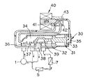
一方、四方弁は、図4及び図5に示すように、シリンダハウジング30内にスプール31を収容している。このスプール31は一端に小径ピストン32と大径ピストン33とを備え、それらのピストン32,33によってシリンダハウジング30内を2つの圧力室34,35に形成している。さらに、シリンダハウジング30には、連通孔36,37,38,39,が形成され、スプール31によって4つのポートのうちの2つづつを選択的に連通する
この四方弁4は、パイロット弁40を備え、3つのポート41,42,43を有している。そして、ポート42はシリンダハウジング30の圧力室34と連通され、ポート41はシリンダハウジング30のポート38と連通され、ポート43はシリンダハウジング30の圧力室35と連通されている。
【0019】
したがって、この四方弁4では、小径ピストン32と大径ピストン33に作用する圧力によって作動される。パイロット弁40を図4のように作動してポート42とポート43とを連通させると、圧力室34と圧力室35が連通されるため、スプール31には該スプール31を左方に移動させる力が生じ、それによってスプール31は左方に移動される。そして、ポート36とポート39が連通され、ポート37とポート38とが連通される。
【0020】
また、パイロット弁40が図5のように作動してポート41とポート43とを連通させると、圧力室35はポート38と連通され、この場合に、小径ピストン32に作用する圧力(P1 )が大径ピストンに作用する圧力(P2 )よりも大きく、スプール31を左方へ移動させる力(P2 ×S2 (但し、S2は小径ピストン32の圧力作用面積))よりも右方へ移動させる力(P1 ×S1 (但し、S1 は大径ピストン33の圧力作用面積))の方が大きい場合には、スプール31は図5に示したように右方に移動される。
【0021】
上述した定速型圧縮機1a、P/C圧縮機1b、第一の内部コントロール回路2cの高圧開放弁9a、第二の内部コントロール回路2dの低圧開放弁9b,外部コントロール回路2fの戻し弁9c、四方弁4のパイロット弁40等は制御装置50によって後述するように制御される。また、圧縮機1の吐出側には、圧縮機1の吐出圧を検出するセンサ60が設けられ、このセンサ60の検出信号は制御装置50に入力される。
【0022】
次に、この実施の形態の作用について説明する。
冷房運転の場合は、各圧縮機1a,1bからの吐出冷媒は、オイルセパレータ3及び四方弁4を介して室外熱交換器5へ送られた後、室内ユニット200を循環してアキュームレータ8に送られる。四方弁4を切替えて、冷媒の流れを変えれば、暖房運転が行われる。
【0023】
室内の空調負荷(馬力)が変動する時には、(1)各圧縮機1a,1bのON,OFF、(2)外部コントロール回路9cの戻し弁9cのON,OFF、(3)第一の内部コントロール回路2cの高圧開放弁9a及び第二の内部コントロール回路2dの低圧開放弁9bのON,OFFにより、図6に示すように、能力(馬力)を1馬力毎に制御する。
【0024】
例えば、要求馬力が10馬力の場合には、2台の圧縮機1a,1bをONにする。この場合に、内部コントロール回路2cの高圧開放弁9aはONになり、P/C圧縮機1bの制御ポート25には、高圧のオイルが加えられる。P/C圧縮機1bは図3の状態になる。要求馬力が9馬力の場合には、2台の圧縮機1a,1bをONにするとともに、戻し弁9cをONにすることにより、外部コントロール回路2fにより1馬力分の吐出量がアキュームレータ8に戻され、9馬力での運転が行われる。要求馬力が8馬力の場合には、2台の圧縮機1a,1bをONにするとともに、戻し弁9cをOFFの状態のまま、高圧開放弁9aをOFFにして低圧開放弁9bをONにする。
【0025】
この場合には、図2に示すように、パワーコントロール機構の作用により、P/C圧縮機1bの馬力は2馬力(ハーフパワー)となり、他方の定速型圧縮機1aの馬力は6馬力であるから、合計8馬力となる。要求馬力が7馬力の場合には、2台の圧縮機1a,1bをONにするとともに、戻し弁9cをONにし、高圧開放弁9aをOFFにして低圧開放弁9bをONにする。
【0026】
この場合には、パワーコントロール機構の作用により、P/C圧縮機1bは2馬力となり、外部コントロール回路2fにより1馬力分の吐出量がアキュームレータ8に戻されるので、合計7馬力になる。以下同様に、図6に示すように、定速型圧縮機1a、P/C圧縮機1b、高圧開放弁9a、低圧開放弁9b及び戻し弁9cのON、OFFを組み合わせることにより、1馬力から10馬力まで1馬力ずつの細かな制御が可能となる。
【0027】
この実施の形態によれば、冷媒回路中の冷媒の高圧と低圧との圧力差が発生しないと、四方弁4の切替えを行なうことができないことになる。
P/C圧縮機1bにおいては、起動初期は圧力上昇の過渡期であり、図2を参照して、万一孔14,15が塞がれない場合には、この圧縮機1bはアンロード状態となり、冷媒回路中の冷媒の高圧と低圧との圧力差が発生しない。これでは、四方弁4の切替えを行なうことができない。そこで、この実施の形態によれば、起動初期においては、P/C圧縮機1bを運転せずに、必ず、定速型圧縮機1aを所定時間運転させて、冷媒回路中の冷媒の高圧と低圧との圧力差が発生した後に、四方弁4を切替える。
【0028】
そして、圧縮機1からの吐出圧が、四方弁4のスプール31を作動させるに十分な圧力になった場合には、センサ60の検出信号が制御装置50に入力されて、空調負荷に応じた冷暖房運転が行なわれる。
【0029】
【発明の効果】
以上述べたように本発明に係る空気調和機及びその制御方法によれば、起動初期において、定速型圧縮機を作動させて、冷媒回路中の冷媒の高圧と低圧との圧力差が発生した後に、四方弁を切替えるので、この四方弁には大きな圧力が作用するので、冷暖房運転の切換えをほぼ確実に行うことができる。
【図面の簡単な説明】
【図1】本発明に係る空気調和機の一実施の形態を示す回路図である。
【図2】P/C圧縮機に内蔵されたパワーコントロール機構の低圧付与状態を示す断面図である。
【図3】P/C圧縮機に内蔵されたパワーコントロール機構の高圧付与状態を示す断面図である。
【図4】四方弁を概念的に示した断面図で、スプールが一方へ作動された状態を示した図である。
【図5】四方弁のスプールが他方へ作動された状態を示した概念的な断面図である。
【図6】本発明に係る空気調和機の能力可変制御を示す図である。
【符号の説明】
1 圧縮機
1a 定速型圧縮機
1b P/C圧縮機
4 四方弁
31 差圧ピストン
36,37,38,39 ポート
40 パイロット弁
41,42,43 ポート
50 制御装置
60 圧力センサ[0001]
TECHNICAL FIELD OF THE INVENTION
The present invention relates to an air conditioner and a control method thereof, in particular, a variable displacement compressor having a power control mechanism and a constant speed compressor interposed in a refrigerant circuit in parallel, and a four-way compressor having a differential pressure piston. The present invention relates to an air conditioner capable of switching between a cooling operation and a heating operation by a valve and a control method thereof.
[0002]
[Prior art]
2. Description of the Related Art Generally, there is known an air conditioner in which a variable capacity compressor and a constant speed compressor are provided in parallel in a refrigerant circuit, and a cooling / heating operation can be switched by switching a four-way valve. In this type, the four-way valve is generally provided with a differential pressure piston, which guides the refrigerant on the discharge side of the compressor to the small-diameter piston-side pressure chamber formed by the differential-pressure piston, and also controls the large-diameter piston-side pressure. The discharge side refrigerant or the suction side refrigerant of the compressor is selectively guided to the chamber, and the four-way valve is switched.
[0003]
In those using an inverter for the variable capacity compressor, the four-way valve is switched after starting the inverter compressor to generate a pressure difference between the high pressure and the low pressure of the refrigerant in the refrigerant circuit, Conventionally, the switching has been performed smoothly.
[0004]
[Problems to be solved by the invention]
However, in the case of using a variable-capacity compressor having a power control mechanism, which enables mechanical capacity switching control without using an inverter compressor, when the variable-capacity compressor is operated at startup, In addition, it takes time for the discharge pressure to rise to the predetermined pressure, which causes a problem that a high pressure is not generated in the refrigerant circuit and the four-way valve for the cooling / heating operation cannot be switched.
[0005]
Therefore, an object of the present invention is to solve the above-mentioned problems of the conventional technology and to provide an air conditioner capable of reliably and quickly switching between heating and cooling operations using a four-way valve and a control method thereof. To provide.
[0006]
[Means for Solving the Problems]
The invention according to
[0007]
The invention according to
[0009]
According to these inventions, a large differential pressure is always generated in the piston of the four-way valve in the early stage of the start of the compressor, so that the four-way valve can be switched reliably and promptly, thereby reliably switching the heating and cooling operation. And quickly.
[0010]
BEST MODE FOR CARRYING OUT THE INVENTION
Hereinafter, a first embodiment of the present invention will be described with reference to the drawings.
In FIG. 1,
The
[0011]
The constant speed compressor 1a has an output of, for example, 6 hp, and the P / C compressor 1b has a maximum output of 4 hp, and the output can be reduced to 2 hp. The
[0012]
The mechanism of the P / C compressor 1b described above will be briefly described. As shown in FIGS. 2 and 3, a rotary compressor element is housed in a sealed
[0013]
Pistons 19 and 20 are housed in the
[0014]
In the P / C compressor 1b having the above-described configuration, the low pressure side of the refrigerant circuit communicates with the
[0015]
In this air conditioner, a first
The
[0016]
According to this embodiment, referring to FIG. 1, first, the high-pressure release valve 9a is opened, and the low-pressure release valve 9b is closed. In this state, the oil separated by the
[0017]
Next, the high pressure release valve 9a is closed, and the low pressure release valve 9b is opened. In this state (the state of FIG. 2), the low-pressure fluid of the suction pipe 2e acts on the
[0018]
On the other hand, the four-way valve accommodates a
[0019]
Therefore, the four-
[0020]
When the
[0021]
The above-mentioned constant speed compressor 1a, P / C compressor 1b, high pressure release valve 9a of the first
[0022]
Next, the operation of this embodiment will be described.
In the case of the cooling operation, the refrigerant discharged from each of the compressors 1a and 1b is sent to the
[0023]
When the indoor air-conditioning load (horsepower) fluctuates, (1) ON / OFF of each compressor 1a, 1b, (2) ON / OFF of the
[0024]
For example, when the required horsepower is 10 horsepower, the two compressors 1a and 1b are turned on. In this case, the high pressure release valve 9a of the
[0025]
In this case, as shown in FIG. 2, the horsepower of the P / C compressor 1b becomes 2 horsepower (half power) and the horsepower of the other constant speed compressor 1a becomes 6 horsepower due to the action of the power control mechanism. That's a total of eight horsepower. When the required horsepower is 7 hp, the two compressors 1a and 1b are turned on, the
[0026]
In this case, due to the operation of the power control mechanism, the P / C compressor 1b has two horsepower, and the discharge amount for one horsepower is returned to the
[0027]
According to this embodiment, the four-
In the P / C compressor 1b, the initial stage of the start-up is a transition period of the pressure rise. Referring to FIG. 2, if the
[0028]
When the discharge pressure from the
[0029]
【The invention's effect】
As described above, according to the air conditioner and the control method thereof according to the present invention, in the initial stage of operation, the constant-speed compressor is operated to generate a pressure difference between the high pressure and the low pressure of the refrigerant in the refrigerant circuit. Later, since the four-way valve is switched, a large pressure acts on the four-way valve, so that the switching of the cooling / heating operation can be performed almost certainly.
[Brief description of the drawings]
FIG. 1 is a circuit diagram showing one embodiment of an air conditioner according to the present invention.
FIG. 2 is a cross-sectional view showing a low pressure application state of a power control mechanism built in the P / C compressor.
FIG. 3 is a cross-sectional view showing a state where a high pressure is applied to a power control mechanism built in the P / C compressor.
FIG. 4 is a sectional view conceptually showing a four-way valve, showing a state where a spool is operated to one side.
FIG. 5 is a conceptual cross-sectional view showing a state where the spool of the four-way valve is operated to the other side.
FIG. 6 is a diagram showing a variable capacity control of the air conditioner according to the present invention.
[Explanation of symbols]
DESCRIPTION OF
Claims (2)
Priority Applications (1)
| Application Number | Priority Date | Filing Date | Title |
|---|---|---|---|
| JP33106095A JP3553714B2 (en) | 1995-11-27 | 1995-11-27 | Air conditioner and control method thereof |
Applications Claiming Priority (1)
| Application Number | Priority Date | Filing Date | Title |
|---|---|---|---|
| JP33106095A JP3553714B2 (en) | 1995-11-27 | 1995-11-27 | Air conditioner and control method thereof |
Publications (2)
| Publication Number | Publication Date |
|---|---|
| JPH09145185A JPH09145185A (en) | 1997-06-06 |
| JP3553714B2 true JP3553714B2 (en) | 2004-08-11 |
Family
ID=18239412
Family Applications (1)
| Application Number | Title | Priority Date | Filing Date |
|---|---|---|---|
| JP33106095A Expired - Fee Related JP3553714B2 (en) | 1995-11-27 | 1995-11-27 | Air conditioner and control method thereof |
Country Status (1)
| Country | Link |
|---|---|
| JP (1) | JP3553714B2 (en) |
-
1995
- 1995-11-27 JP JP33106095A patent/JP3553714B2/en not_active Expired - Fee Related
Also Published As
| Publication number | Publication date |
|---|---|
| JPH09145185A (en) | 1997-06-06 |
Similar Documents
| Publication | Publication Date | Title |
|---|---|---|
| US4382370A (en) | Refrigerating system using scroll type compressor | |
| JP3119946B2 (en) | Combined lift / piston / axial port unloader for screw compressor | |
| KR970066424A (en) | Refrigeration circuit with fluid flow control | |
| JP2013124600A (en) | Screw compressor | |
| US6024547A (en) | Power-variable compressor and air conditioner using the same | |
| US6247322B1 (en) | Air conditioning systems | |
| JPH11324930A (en) | Variable capacity type compressor | |
| JP3553714B2 (en) | Air conditioner and control method thereof | |
| JP2000161796A (en) | Air conditioner | |
| JP3634472B2 (en) | Air conditioner | |
| JP2002070779A (en) | Screw-type fluid machine | |
| JP3979717B2 (en) | Air conditioner | |
| JP3338256B2 (en) | Air conditioner | |
| TWI715330B (en) | Two-stage compressor | |
| JP2000177375A (en) | Air conditioner | |
| JPH10196568A (en) | Compressor and air conditioner | |
| JPH1163738A (en) | Freezer device | |
| JPH09138010A (en) | Air conditioner | |
| JP3837208B2 (en) | Air conditioner | |
| JPH0720385Y2 (en) | Mechanism of shock reduction of compressor in air conditioner | |
| JP3588216B2 (en) | Compressors and air conditioners | |
| JP3585149B2 (en) | Compressors and air conditioners | |
| JPS6229789A (en) | Rotary compressor | |
| JPH0784873B2 (en) | Variable capacity van compressor | |
| JPH09126559A (en) | Air conditioner |
Legal Events
| Date | Code | Title | Description |
|---|---|---|---|
| TRDD | Decision of grant or rejection written | ||
| A01 | Written decision to grant a patent or to grant a registration (utility model) |
Free format text: JAPANESE INTERMEDIATE CODE: A01 Effective date: 20040420 |
|
| A61 | First payment of annual fees (during grant procedure) |
Free format text: JAPANESE INTERMEDIATE CODE: A61 Effective date: 20040430 |
|
| FPAY | Renewal fee payment (event date is renewal date of database) |
Free format text: PAYMENT UNTIL: 20080514 Year of fee payment: 4 |
|
| FPAY | Renewal fee payment (event date is renewal date of database) |
Free format text: PAYMENT UNTIL: 20090514 Year of fee payment: 5 |
|
| LAPS | Cancellation because of no payment of annual fees |