JP3553584B2 - Congestion control method in packet transfer device, program for executing the method, and recording medium recording the program - Google Patents
Congestion control method in packet transfer device, program for executing the method, and recording medium recording the program Download PDFInfo
- Publication number
- JP3553584B2 JP3553584B2 JP2001056222A JP2001056222A JP3553584B2 JP 3553584 B2 JP3553584 B2 JP 3553584B2 JP 2001056222 A JP2001056222 A JP 2001056222A JP 2001056222 A JP2001056222 A JP 2001056222A JP 3553584 B2 JP3553584 B2 JP 3553584B2
- Authority
- JP
- Japan
- Prior art keywords
- user group
- packet
- output port
- closed user
- control method
- Prior art date
- Legal status (The legal status is an assumption and is not a legal conclusion. Google has not performed a legal analysis and makes no representation as to the accuracy of the status listed.)
- Expired - Lifetime
Links
Images

Landscapes
- Data Exchanges In Wide-Area Networks (AREA)
Description
【0001】
【発明の属する技術分野】
本発明は、IPネットワークを構成するパケット転送装置の品質制御機能に係り、特に閉域ユーザグループ(Closed User Group;以下、単に“CUG”という)機能を有するパケット転送装置内の輻輳制御方法および該輻輳制御方法を実行するためのプログラム、ならびに該プログラムを記録したコンピュータ読み取り可能な記録媒体に関するものである。
【0002】
【従来の技術】
まず、本発明の基本となる従来のパケッ卜転送装置における輻輳制御方法の一例を図面を用いて説明する。
図3は、CUG機能を有する従来のパケット転送装置の機能ブロック図である。同図に示すように、CUG機能を有する従来のパケット転送装置は、入力ポート311〜31m側にパケットフォワーダ321〜32m、出力ポート381〜38p側に出力方路別バッファ351〜35n、スケジューラ371〜37p、そして複数の入出力ポートを接続するスイッチ部34で構成されている。
【0003】
入力ポート311〜31mから送信されてきたパケットは、パケットフォワーダ321〜32mに送信される。パケットフォワーダ321〜32mでは、パケット毎にCUG単位で分離されたルーティングテーブルから転送すべき出力方路および出力ポートを検索した後、パケットをスイッチ部34に送信する。
【0004】
スイッチ部34では、パケットフォワーダ321〜32mにおける検索結果に基づき該当する出力ポートおよび出力方路別にパケットをスイッチングし、送信する出力方路毎に設置した出力方路別バッファ351〜35nに送信し、該出力方路別バッファ351〜35nに蓄積する。出力方路別バッファ351〜35nに蓄積されたパケットは、スケジューラ371〜37pによって順次読み出され、出力ポート381〜38pから送信される。
【0005】
一方、特定の出力ポートへのパケットが集中した場合、スイッチ部34において輻輳状態が発生する。このとき、出力ポート側では、当該出力ポートの特定の出力方路向けのパケットが集中することとなり、当該出力方路別バッファのパケット蓄積量が増加する。出力方路別バッファ351〜35nには、輻輳を検出するための閾値361〜36nを予め設定し、パケット蓄積量が閾値を超えた場合に、輻輳通知39として、当該出力ポート識別子をスイッチ部34または前段のパケットフォワーダ321〜32mに通知する。パケットフォワーダ321〜32mまたはスイッチ部34では、当該出力ポート向けのパケットの、パケットフォワーダからスイッチ部34への送信を停止するか、スイッチ部34から出力ポート側への送信を停止することで、輻輳を抑止する。
【0006】
【発明が解決しようとする課題】
以上のような従来の輻輳制御方法では、出力ポート側にて輻輳を検出した場合に、当該出力ポート向けに転送するパケットの送信をすべて停止する。これによりCUG間および同一CUG内の受信ユーザ間でトラヒック干渉が発生した。すなわち、あるCUG内で輻輳状態になるようなトラヒックが発生した場合に、その影響を他のCUGが受けて他のCUGのパケット送信も停止され、廃棄される可能性があった。また、同一CUG内の受信ユーザ間において、独立した通信を行っている場合においても、一方のユーザの影響を受けて、別のユーザのパケット送信が停止され、廃棄される可能性があった。
【0007】
本発明の目的は、CUG間でのトラヒック干渉を防止すること、および同一CUG内の受信ユーザ間でのトラヒック干渉を防止することが可能な閉域ユーザグループ(CUG)機能を有するパケット転送装置内の輻輳制御方法および該輻輳制御方法を実行するためのプログラム、ならびに該プログラムを記録したコンピュータ読み取り可能な記録媒体を提供することにある。
【0008】
【課題を解決するための手段】
上記課題を解決するために、請求項1の発明においては、アクセスリンク方向への出力処理において、出力ポート側にてCUG毎かつ受信ユーザ毎にバッファを設定し、各バッファには閾値を設け、バッファにおけるパケットの蓄積量がその閾値を超えた場合に、該当するCUGと受信ユーザを前段に設けた廃棄制御部に通知する。廃棄制御部では、当該CUG内の当該ユーザ向けのパケットを廃棄する。
【0009】
請求項2の発明においては、アクセスリンク方向への出力処理において、出力ポート側にてCUG毎かつ受信ユーザ毎にバッファを設定し、各バッファには閾値を設け、バッファにおけるパケットの蓄積量がその閾値を超えた場合に、該当するCUGを前段に設けた廃棄制御部に通知する。廃棄制御部では、当該CUG向けのパケットを廃棄する。
【0010】
請求項3の発明においては、中継リンク方向への出力処理において、出力ポート側にてCUG毎にバッファを設定し、各バッファには閾値を設け、バッファにおけるパケットの蓄積量がその閾値を超えた場合に、該当するCUGを前段に設けた廃棄制御部に通知する。廃棄制御部では、当該CUG向けのパケットを廃棄する。
【0011】
請求項4の発明においては、請求項1〜3の発明に従いつつも、出力ポート側のバッファにおいて輻輳状態を検出した際に送出する輻輳通知を、スイッチ部の前段に設けた廃棄制御部に通知し、当該廃棄制御部においてパケットの廃棄処理を行う。
【0012】
請求項5の発明においては、請求項1〜4の発明に従いつつも、出力ポート側から廃棄制御部に対して輻輳状態を通知する際に、CUGを特定するための情報として、出力ポート識別子とCUG識別子を通知し、CUG内の受信ユーザを特定するための情報として、出力ポート識別子とCUG識別子および受信ユーザの宛先アドレスを通知する。
【0013】
請求項6の発明においては、請求項1〜4発明に従いつつも、出力ポート側から廃棄制御部に対して輻輳状態を通知する際に、CUGを特定するための情報として、出力ポート識別子と当該CUGを収容するVPI/VCIを通知し、CUG内の受信ユーザを特定するための情報として、出力ポート識別子と当該CUG内の当該ユーザを収容するVPI/VCIを通知する。
【0014】
請求項7の発明においては、請求項1〜6の発明に従いつつも、廃棄制御部では、出力ポート側からの輻輳通知を受けて輻輳を検知し、出力ポート側から受けた輻輳通知に基づき、廃棄すべきパケットのフィルタリング処理を行い、該当するパケットを廃棄する。
【0015】
請求項8の発明においては、請求項1および請求項2の発明に従いつつも、出力ポート側においてCUG毎かつ受信ユーザ毎に個別に設定したバッファに一旦蓄積してから送信する際に、ユーザ毎に契約帯域を設定し、その契約帯域に基づいて帯域割当型のスケジューラを用いて各バッファから読み出しを行う。
【0016】
請求項9の発明においては、請求項3の発明に従いつつも、アクセスリンクにはユーザ毎に契約帯域を設定し、中継リンクの出力帯域を、各CUG毎に当該リンクに接続されている同一CUGユーザの契約帯域の総和(すなわち当該パケット転送装置内に収容された同一CUGユーザの受信契約帯域の総和)、または、当該リンクを介して接続された他のパケット転送装置に収容された同一CUGユーザの契約帯域の総和(すなわち、他のパケット転送装置に収容された同一CUGユーザの送信契約帯域の総和)のどちらか小さい方を下回らないように設定する。
【0017】
請求項10の発明においては、請求項3の発明に従いつつも、アクセスリンクにはユーザ毎に契約帯域を設定し、出力ポート側のCUG別バッファからスケジューラにて読み出す際に、各CUG毎に当該リンクに接続されている同一CUGユーザの契約帯域の総和(すなわち当該パケット転送装置内に収容された同一CUGユーザの受信契約帯域の総和)、または、当該リンクを介して接続された他のパケット転送装置に収容された同一CUGユーザの契約帯域の総和(すなわち、他のパケット転送装置に収容された同一CUGユーザの送信契約帯域の総和)のどちらか小さい方の帯域を算出し、算出した帯域に基づき、帯域割当型のスケジューラを用いて、各バッファから読み出しを行う。
【0018】
本発明においては、内部スイッチ内における輻輳を抑制する際に、出力ポート側でCUG内の受信ユーザ毎にバッファを設けることにより、受信ユーザ単位で輻輳を検出し、検出した受信ユーザとそのCUGを前段に設けた廃棄制御部に通知することにより、廃棄制御部において受信ユーザ単位で輻輳の原因となるパケットを事前に廃棄することが可能となり、結果としてアクセスリンク側への出力方向において、受信ユーザ間でのトラヒックの干渉が抑止される。
【0019】
また、内部スイッチ内における輻輳を抑制する際に、出力ポート側でCUG内の受信ユーザ毎にバッファを設けることにより、受信ユーザ単位で輻輳を検出し、検出した受信ユーザの属するCUGを前段に設けた廃棄制御部に通知することにより、廃棄制御部においてCUG単位で輻輳の原因となるパケットを事前に廃棄することが可能となり、結果としてアクセスリンク側への出力方向において、CUG間でのトラヒックの干渉が抑止される。
【0020】
また、内部スイッチ内における輻輳を抑制する際に、出力ポート側でCUG毎にバッファを設けることにより、CUG単位で輻輳を検出し、検出したCUGを前段に設けた廃棄制御部に通知することにより、廃棄制御部においてCUG単位で輻輳の原因となるパケットを事前に廃棄することが可能となり、結果として中継リンク側への出力方向において、CUG間でのトラヒックの干渉が抑止される。
【0021】
また、出力ポート側から輻輳状態の通知を、スイッチ部の前段に設けた廃棄制御部に通知し、当該廃棄制御部においてパケットの廃棄処理を行うことで、スイッチ部における輻輳を事前に抑止する。
【0022】
また、出力ポート側から廃棄制御部に対して輻輳状態を通知する際に、CUGを特定するための情報として、出力ポート識別子とCUG識別子を用い、CUG内の受信ユーザを特定するための情報として、出力ポート識別子とCUG識別子および受信ユーザの宛先アドレスを用いることで、廃棄制御部において廃棄すべきパケットのフィルタリング処理を可能とする。
【0023】
また、出力ポート側から廃棄制御部に対して輻輳状態を通知する際に、CUGを特定するための情報として、出力ポート識別子と当該CUGを収容するVPI/VCIを通知し、閉域ユーザグループ内の受信ユーザを特定するための情報として、出力ポート識別子と該当閉域ユーザグループを収容するVPI/VCIを通知することで、通知する情報量を削減し、廃棄制御部におけるパケットのフィルタリング処理を可能とする。
【0024】
また、出力ポート側に設けたバッファにおけるパケットの蓄積量がその閾値を超えた場合に、前段に設けた廃棄制御部に輻輳通知を送ることにより、廃棄制御部における廃棄処理を行うトリガーとする。
【0025】
また、出力ポート側において受信ユーザ毎に個別に設定したバッファに一旦蓄積してから送信する際に、ユーザ毎に契約帯域を設定し、その契約帯域に基づいて帯域割当型のスケジューラを用いて各バッファから読み出すことで、ユーザ毎に受信帯域を確保し、受信ユーザ間の帯域干渉を抑止する。
【0026】
また、アクセスリンクにはユーザ毎に契約帯域を設定し、中継リンクの出力帯域を、各CUG毎に当該リンクに接続されている同一CUGユーザの契約帯域の総和(すなわち当該パケット転送装置内に収容された同一CUGユーザの受信契約帯域の総和)、または、当該リンクを介して接続された他のパケット転送装置に収容された同一CUGユーザの契約帯域の総和(すなわち、他のパケット転送装置に収容された同一CUGユーザの送信契約帯域の総和)のどちらか小さい方を下回らないように設定することで、CUG毎にアクセスリンクに設定した契約帯域の受信帯域を確保し、CUG間の帯域干渉を抑止する。
【0027】
また、アクセスリンクにはユーザ毎に契約帯域を設定し、中継リンクに接続した出力ポート側のCUG別バッファからスケジューラにて読み出す際に、各CUG毎に当該リンクに接続されている同一CUGユーザの契約帯域の総和(すなわち当該パケット転送装置内に収容された同一CUGユーザの受信契約帯域の総和)、または、当該リンクを介して接続された他のパケット転送装置に収容された同一CUGユーザの契約帯域の総和(すなわち、他のパケット転送装置に収容された同一CUGユーザの送信契約帯域の総和)のどちらか小さい方の帯域を算出し、算出した帯域に基づき、帯域割当型のスケジューラを用いて、各バッファから読み出しを行うことで、バッファから読み出す際のCUG間の帯域干渉を抑止する。
【0028】
【発明の実施の形態】
以下、本発明の実施例を図面を用いて詳細に説明する。
本実施例は、本発明による輻輳制御方法を用いてIP−VPN(Internet Protocol−Virtual Private Network)を実現する場合とし、パケット転送装置に接続されたアクセスリンクおよび中継リンクは、ATM(Asyncronous Transfer Mode)プロトコルを用いるものとする。
【0029】
(実施例1)
まず、本発明の第1の実施例を説明する。
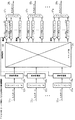
図1は、本発明に係る輻輳制御方法を用いて、アクセスリンク側へ出力する際のパケット転送装置内の機能ブロック図である。
図1に示すように、パケット転送装置は、入力ポート111〜11m側に設けられたパケットフォワーダ121〜12mおよび廃棄制御部131〜13mと、出力ポート181〜18p側に設けられたユーザ別バッファ151〜15nおよびスケジューラ171〜17pと、複数の入出力ポートを接続するスイッチ部14とで構成される。なお、本実施例におけるユーザ別バッファは、複数のCUGにまたがって属している場合はそれぞれにユーザ別バッファを設定するものとする。第1の実施例におけるこのようなユーザ別バッファを“閉域ユーザグループ毎かつ受信ユーザ毎”と呼ぶ(請求項1,2参照)。
【0030】
以下、第1の実施例の動作を、図1を用いて詳細に説明する。
入力ポート111〜11mから送信されてきたパケットは、パケットフォワーダ121〜12mに送信される。パケットフォワーダ121〜12mでは、CUG毎にIPレイヤにおけるパケット転送処理が施され、この結果に基づき送信すべき出力ポートおよび出力VPI/VCIが検索された後、パケットは廃棄制御部131〜13mを介して、スイッチ部14に送信される。
【0031】
なお、廃棄制御部131〜13mでは、以前のパケット転送の際に後述するユーザ別バッファ151〜15nのパケット蓄積量が閾値161〜16nを超えた場合に、当該ユーザ別バッファ151〜15nから送られた輻輳通知に基づいてパケットを廃棄する処理を行う(詳細は後述)。
【0032】
スイッチ部14では、パケットを当該出力ポートかつ当該出力VPI/VCI向けにスイッチングし、CUG内の受信ユーザ毎に設定されたユーザ別バッファ151〜15nに送信し蓄積する。
【0033】
ユーザ別バッファ151〜15nに蓄積されたパケットは、スケジューラ171〜17pによって順次読み出され出力ポート181〜18pからアクセスリンクへ送信される。ここでは、CUG内のユーザ毎にアクセスリンクに契約帯域を設定し、その契約帯域に基づきスケジューリングされ、ATMセル単位で出力ポートから送信する。スケジューラ171〜17pにおけるスケジューリングアルゴリズムとしては、例えばWRR(Weighted Round Robin)を用いる。
【0034】
なお、特定の出力ポートへのパケットが集中した場合、スイッチ部14では輻輳状態が発生する。この場合、出力ポート側では当該出力ポートの特定ユーザ向けのパケットが集中することとなり、当該ユーザ別バッファのパケット蓄積量が増加する。そのため、ユーザ別バッファ151〜15nには予め所定の閾値161〜16nを設定しておく。
【0035】
そして、あるユーザ別バッファにおけるパケットの蓄積量が予め設定されている閾値を超えた場合には、輻輳状態にあることを検出し、前段に設けられた廃棄制御部131〜13mへの輻輳通知19として、該当する出力ポート識別子と当該ユーザのCUG識別子および宛先IPアドレス/ネットマスクを通知した後、ユーザ別バッファ151〜15nに蓄積されているパケットは、スケジューラ171〜17pによって順次読み出され出力ポート181〜18pからアクセスリンクへ送信される。
【0036】
なお、CUG単位で廃棄制御する場合は、輻輳通知19として、該当する出力ポート識別子と当該ユーザのCUG識別子を通知する。
【0037】
また、廃棄制御部131〜13mへ通知する情報を削減するために、当該ユーザのCUG識別子と宛先IPアドレス/ネットマスクの代わりに当該ユーザを収容するVPI/VCIを、CUG単位で廃棄制御する場合は、当該ユーザのCUG識別子の代わりに当該CUGユーザを収容するVPI/VCIを通知することも可能である。
【0038】
廃棄制御部131〜13mは、出力ポート側から輻輳通知19を受けると、輻輳状態を検知し、これをトリガーとして輻輳通知19に基づき廃棄すべきパケットをフィルタリング処理し、フィルタリング条件に該当したパケットに対して廃棄処理を行う。
【0039】
フィルタリング処理では、輻輳通知19に基づき廃棄すべきパケットのリストを保持し、このリストを検索テーブル(図示せず)として、入力ポート側から廃棄制御部131〜13mにパケットが転送されてくる毎に該当するパケットかどうかを検索テーブルで検索し、該当するパケットであれば廃棄し、該当しないパケットであれば、そのまま通過させる処理を行う。
【0040】
このように、スイッチ部14における輻輳の原因となるパケットを輻輳状態が発生する前段の廃棄制御部131〜13mで事前に廃棄することで、アクセスリンク方向への出力処理において、受信ユーザ間のトラヒック干渉を抑止し、ユーザの受信帯域を確保することが可能となる。なお、CUG単位で廃棄制御する場合は、CUG間のトラヒック干渉を抑止し、CUG毎に帯域を確保することが可能となる。
【0041】
(実施例2)
次に、本発明の第2の実施例を説明する。
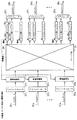
図2は、同一パケット転送装置における、中継リンク側へ出力する際の機能ブロック図である。
図2に示すように、パケット転送装置は、入力ポート211〜21m側に設けられたパケットフォワーダ221〜22mおよび廃棄制御部231〜23mと、出力ポート281〜28p側に設けられたCUG別バッファ251〜25nおよびスケジューラ271〜27pと、複数の入出力ポートを接続するスイッチ部24とで構成される。
【0042】
以下、第2の実施例の動作を、図2を用いて詳細に説明する。
入力ポート211〜21mから送信されてきたパケットは、パケットフォワーダ221〜22mに送信される。パケットフォワーダ221〜22mでは、CUG毎にIPレイヤにおけるパケット転送処理が施され、この結果に基づき送信すべき出力ポートおよび出力VPI/VCIが検索された後、パケットは廃棄制御部231〜23mを介して、スイッチ部24に送信される。
【0043】
なお、廃棄制御部231〜23mでは、以前のパケット転送の際に後述するCUG別バッファ251〜25nのパケット蓄積量が閾値261〜26nを超えた場合に、当該CUG別バッファ251〜25nから送られた輻輳通知に基づいてパケットを廃棄する処理を行う(詳細は後述)。
【0044】
スイッチ部24では、パケットを当該出力ポートかつ当該出力VPI/VCI向けにスイッチングし、CUG毎に設定されたCUG別バッファ251〜25nに送信し蓄積する。
【0045】
CUG別バッファ251〜25nに蓄積されたパケットは、スケジューラ271〜27pによって順次読み出され出力ポート281〜28pから中継リンクへ送信される。
【0046】
中継リンクの出力帯域として、CUG毎に、当該リンクに収容されている同一CUGユーザの契約帯域の総和(すなわち当該パケット転送装置内に収容された同一CUGユーザの受信契約帯域の総和)、または、当該リンクを介して接続された他のパケット転送装置に収容された同一CUGユーザの契約帯域の総和(すなわち、他のパケット転送装置に収容された同一CUGユーザの送信契約帯域の総和)のどちらか小さい方を下回らないように設定し、CUG毎にその帯域を重み付けとしてWRRスケジューリングを行い、ATMセル単位で出力ポートから送信する。
【0047】
なお、特定の出力ポートへのパケットが集中した場合、スイッチ部24では輻輳状態が発生する。この場合、出力ポート側では当該出力ポートの特定CUG向けのパケットが集中することとなり、当該CUG別バッファのパケット蓄積量が増加する。CUG別バッファ251〜25nには予め所定の閾値261〜26nを設定しておく。
【0048】
そして、あるCUG別バッファにおけるパケットの蓄積量が設定されている閾値を超えた場合は、輻輳状態にあることを検出し、前段に設けられた廃棄制御部231〜23mへの輻輳通知29として、該当する出力ポート識別子と当該CUGのCUG識別子を通知する。
【0049】
この際、廃棄制御部231〜23mへ通知する情報を削減するために、当該ユーザのCUG識別子の代わりに当該CUGを収容するVPI/VCIを通知することも可能である。
【0050】
廃棄制御部231〜23mでは、出力ポート側から輻輳通知29を受けることにより、輻輳状態を検知し、これをトリガーとして輻輳通知29に基づき廃棄すべきパケットをフィルタリング処理し、フィルタリング条件に該当したパケットに対して廃棄処理を行う。
【0051】
このように、スイッチ部における輻輳の原因となるパケットを輻輳状態が発生する前段で事前に廃棄することで、中継リンク方向への出力処理において、CUG間のトラヒック干渉を抑止し、CUG毎に帯域を確保することが可能となる。
【0052】
なお、上記第1の実施例における各処理および第2の実施例における各処理をプログラムコード化して作成したプログラムは、CD−ROM,DVDなどのコンピュータ読み取り可能な記録媒体に記録して流通させたり、ネットワークを介して配布することが可能である。本発明を実現しようとする者は、記録媒体やネットワークから本発明に係るプログラムを入手してシステムにロードすることによって本発明に係る輻輳制御方法を容易に実現することが可能になる。
【0053】
【発明の効果】
以上に説明したように、本発明によれば、CUG内の受信ユーザ単位でパケットの廃棄制御を行うことができるために、IP−VPNを実現する場合に、VPN内の受信ユーザ間の帯域干渉を抑止し、VPN内の受信ユーザ毎に受信帯域の確保が可能となる。
また、CUG単位でパケットの廃棄制御を行うことができるために、VPN間の帯域干渉を抑止し、VPN単位でトラヒックの独立性が確保可能となる。
【図面の簡単な説明】
【図1】本発明に係る輻輳制御方法を用いて、アクセスリンク側へ出力する際のパケット転送装置内の機能ブロック図である(第1の実施例)。
【図2】本発明に係る輻輳制御方法を用いて、中継リンク側へ出力する際のパケット転送装置内の機能ブロック図である(第2の実施例)。
【図3】CUG機能を有する従来のパケット転送装置の機能ブロック図である。
【符号の説明】,
111〜11m,211〜21m,311〜31m:入力ポート
121〜12m,221〜22m,321〜32m:パケットフォワーダ
131〜13m,231〜23m:廃棄制御部
14,24,34:スイッチ部
151〜15n:ユーザ別バッファ
251〜25n:CUG別バッファ
351〜35n:出力方路別バッファ
161〜16n,261〜26n,361〜36n:閾値
171〜17p,271〜27p,371〜37p:スケジューラ
181〜18p,281〜28p,381〜38p:出力ポート
19,29,39:輻輳通知[0001]
TECHNICAL FIELD OF THE INVENTION
The present invention relates to a quality control function of a packet transfer device constituting an IP network, and more particularly to a congestion control method in a packet transfer device having a closed user group (hereinafter, simply referred to as “CUG”) function and the congestion. The present invention relates to a program for executing a control method, and a computer-readable recording medium on which the program is recorded.
[0002]
[Prior art]
First, an example of a congestion control method in a conventional packet transfer device, which is the basis of the present invention, will be described with reference to the drawings.
FIG. 3 is a functional block diagram of a conventional packet transfer device having a CUG function. As shown in the figure, a conventional packet transfer device having a CUG function is composed of a
[0003]
The packets transmitted from the
[0004]
The
[0005]
On the other hand, when packets to a specific output port are concentrated, a congestion state occurs in the
[0006]
[Problems to be solved by the invention]
In the conventional congestion control method as described above, when congestion is detected on the output port side, transmission of all packets to be transferred to the output port is stopped. As a result, traffic interference occurred between CUGs and between receiving users in the same CUG. That is, when traffic occurs such that a congestion state occurs in a certain CUG, another CUG is affected by the traffic and packet transmission of the other CUG may be stopped and discarded. Further, even when independent communication is performed between receiving users in the same CUG, packet transmission of another user may be stopped and discarded due to the influence of one user.
[0007]
An object of the present invention is to provide a packet transfer apparatus having a closed user group (CUG) function capable of preventing traffic interference between CUGs and preventing traffic interference between receiving users in the same CUG. An object of the present invention is to provide a congestion control method, a program for executing the congestion control method, and a computer-readable recording medium on which the program is recorded.
[0008]
[Means for Solving the Problems]
In order to solve the above problem, in the invention of claim 1, in output processing in the access link direction, a buffer is set for each CUG and each receiving user on the output port side, and a threshold is provided for each buffer, When the accumulated amount of packets in the buffer exceeds the threshold, the corresponding CUG and the receiving user are notified to the discard control unit provided in the preceding stage. The discard control unit discards a packet for the user in the CUG.
[0009]
According to the second aspect of the present invention, in the output processing in the access link direction, a buffer is set for each CUG and each receiving user on the output port side, and a threshold is provided for each buffer, and the amount of accumulated packets in the buffer is When the threshold value is exceeded, the corresponding CUG is notified to the discard control unit provided in the preceding stage. The discard control unit discards the packet for the CUG.
[0010]
According to the third aspect of the present invention, in the output processing in the relay link direction, a buffer is set for each CUG on the output port side, a threshold is provided for each buffer, and the amount of accumulated packets in the buffer exceeds the threshold. In this case, the corresponding CUG is notified to the discard control unit provided at the preceding stage. The discard control unit discards the packet for the CUG.
[0011]
According to the fourth aspect of the present invention, a congestion notification to be transmitted when a congestion state is detected in the buffer on the output port side is notified to a discard control unit provided in a preceding stage of the switch unit, while following the inventions of the first to third aspects. Then, the discard control unit performs a packet discarding process.
[0012]
According to the fifth aspect of the present invention, when notifying the congestion state from the output port side to the discard control unit, the output port identifier and the output port identifier are used as information for specifying the CUG, while following the inventions of the first to fourth aspects. The CUG identifier is notified, and the output port identifier, the CUG identifier, and the destination address of the receiving user are notified as information for specifying the receiving user in the CUG.
[0013]
According to the sixth aspect of the present invention, when notifying the congestion state from the output port side to the discard control unit while following the first to fourth aspects of the invention, the output port identifier and the output port identifier are used as information for specifying the CUG. A VPI / VCI accommodating the CUG is notified, and an output port identifier and a VPI / VCI accommodating the user in the CUG are notified as information for specifying a receiving user in the CUG.
[0014]
In the invention of claim 7, while following the invention of claims 1 to 6, the discard control unit detects congestion by receiving congestion notification from the output port side, based on the congestion notification received from the output port side, A filtering process for a packet to be discarded is performed, and the corresponding packet is discarded.
[0015]
According to the eighth aspect of the present invention, when the data is temporarily stored in a buffer set individually for each CUG and each receiving user at the output port side and then transmitted at the output port side, the method according to the first and second aspects of the present invention, , And based on the contracted bandwidth, reading is performed from each buffer by using a bandwidth allocation type scheduler.
[0016]
According to the ninth aspect of the present invention, the contract bandwidth is set for each user on the access link and the output bandwidth of the relay link is set for each CUG in the same CUG connected to the link, while following the invention of the third aspect. The sum of the contract bandwidths of the users (that is, the sum of the reception contract bandwidths of the same CUG user accommodated in the packet transfer device) or the same CUG user accommodated in another packet transfer device connected via the link (I.e., the sum of the transmission contract bandwidths of the same CUG user accommodated in other packet transfer devices), whichever is smaller, is set.
[0017]
According to the tenth aspect of the present invention, the contract bandwidth is set for each user on the access link and the scheduler reads out from the CUG-specific buffer on the output port side for each CUG, while following the invention of the third aspect. The sum of the contracted bandwidths of the same CUG user connected to the link (that is, the sum of the received contracted bandwidths of the same CUG user accommodated in the packet transfer apparatus) or the transfer of another packet connected via the link The smaller of the sum of the contracted bandwidths of the same CUG user accommodated in the device (that is, the sum of the transmission contracted bandwidths of the same CUG user accommodated in another packet transfer device) is calculated. Based on this, reading is performed from each buffer using a band allocation type scheduler.
[0018]
In the present invention, when suppressing congestion in the internal switch, by providing a buffer for each receiving user in the CUG on the output port side, congestion is detected for each receiving user, and the detected receiving user and the CUG are detected. By notifying the discard control unit provided in the preceding stage, it becomes possible for the discard control unit to discard the packet causing the congestion in advance for each receiving user, and as a result, in the output direction to the access link side, the receiving user Interference of traffic between them is suppressed.
[0019]
Further, when suppressing congestion in the internal switch, a buffer is provided for each receiving user in the CUG on the output port side to detect congestion on a receiving user basis, and a CUG to which the detected receiving user belongs is provided in the preceding stage. By notifying the discarding control unit, the discarding control unit can discard the packet causing the congestion in CUG units in advance, and as a result, the traffic between the CUGs in the output direction to the access link side can be reduced. Interference is suppressed.
[0020]
Further, when suppressing congestion in the internal switch, by providing a buffer for each CUG on the output port side, congestion is detected in units of CUG, and the detected CUG is notified to the discard control unit provided in the preceding stage. In addition, the discarding control unit can discard the packet causing the congestion in CUG units in advance, and as a result, the traffic interference between the CUGs is suppressed in the output direction to the relay link side.
[0021]
In addition, a notification of the congestion state is sent from the output port side to a discard control unit provided in a preceding stage of the switch unit, and the discard control unit performs packet discard processing, thereby suppressing congestion in the switch unit in advance.
[0022]
Further, when notifying the congestion state from the output port side to the discard control unit, as information for specifying the CUG, the output port identifier and the CUG identifier are used, and as information for specifying the receiving user in the CUG. By using the output port identifier, the CUG identifier, and the destination address of the receiving user, it is possible to perform a filtering process on a packet to be discarded in the discarding control unit.
[0023]
When the output port notifies the discard control unit of the congestion state, the output port identifier and the VPI / VCI accommodating the CUG are notified as information for specifying the CUG. By notifying the output port identifier and the VPI / VCI accommodating the corresponding closed user group as information for specifying the receiving user, the amount of information to be notified can be reduced, and the packet filtering process in the discard control unit can be performed. .
[0024]
Further, when the accumulated amount of packets in the buffer provided on the output port side exceeds the threshold value, a congestion notification is sent to the discard control unit provided in the preceding stage, thereby setting a trigger for performing the discard process in the discard control unit.
[0025]
In addition, when the data is temporarily stored in a buffer set individually for each receiving user on the output port side and then transmitted, a contracted bandwidth is set for each user, and a bandwidth allocation type scheduler is used based on the contracted bandwidth. By reading from the buffer, a reception band is secured for each user, and band interference between reception users is suppressed.
[0026]
Also, a contract bandwidth is set for each user on the access link, and the output bandwidth of the relay link is set for each CUG by the sum of the contract bandwidths of the same CUG users connected to the link (that is, accommodated in the packet transfer device). Sum of received contract bandwidths of the same CUG user) or the sum of contract bandwidths of the same CUG user accommodated in another packet transfer device connected via the link (that is, accommodated in another packet transfer device). (The sum of the transmission contracted bandwidths of the same CUG user) is not less than the smaller one, so that the reception bandwidth of the contracted bandwidth set for the access link for each CUG is secured, and the band interference between CUGs is reduced. Deter.
[0027]
Also, a contract bandwidth is set for each user on the access link, and when the scheduler reads out from the buffer for each CUG on the output port side connected to the relay link by the scheduler, the same CUG user connected to the link is connected for each CUG. The sum of the contracted bandwidths (that is, the sum of the reception contracted bandwidths of the same CUG user accommodated in the packet transfer apparatus) or the contract of the same CUG user accommodated in another packet transfer apparatus connected via the link A smaller one of the sum of the bands (that is, the sum of the transmission contracted bands of the same CUG user accommodated in another packet transfer device) is calculated, and a band allocation type scheduler is used based on the calculated band. By performing reading from each buffer, band interference between CUGs when reading from the buffer is suppressed.
[0028]
BEST MODE FOR CARRYING OUT THE INVENTION
Hereinafter, embodiments of the present invention will be described in detail with reference to the drawings.
In the present embodiment, an IP-VPN (Internet Protocol-Virtual Private Network) is realized using the congestion control method according to the present invention, and an access link and a relay link connected to a packet transfer apparatus are connected to an ATM (Asynchronous Transfer Mode). ) The protocol shall be used.
[0029]
(Example 1)
First, a first embodiment of the present invention will be described.
FIG. 1 is a functional block diagram in a packet transfer device when outputting to an access link side using the congestion control method according to the present invention.
As shown in FIG. 1, the packet transfer apparatus, the input port 11 1 to 11 and the packet forwarder 12 1 to 12 m and discarding control section 13 1 to 13 m provided on the m-side, the output port 18 1 ~ 18 p-side And the user-specific buffers 15 1 to 15 n and schedulers 17 1 to 17 p, and a
[0030]
Hereinafter, the operation of the first embodiment will be described in detail with reference to FIG.
Packet transmitted from the input port 11 1 to 11 m is transmitted to the packet forwarder 12 1 to 12 m. In the packet forwarder 12 1 to 12 m, the packet forwarding process in the IP layer is performed for each CUG, after the output port and the output VPI / VCI to be transmitted on the basis of this result is searched, the packet discard controller 13 1 - 13m, and transmitted to the
[0031]
In the discard controller 13 1 to 13 m, when the packet accumulated amount of user-specific buffer 15 1 to 15 n to be described later during the previous packet transfer has exceeded the threshold value 16 1 ~ 16 n, the user-specific buffer performs a process of discarding packets based on congestion notification sent from 15 1 to 15 n (described in detail later).
[0032]
In the
[0033]
Packets stored in the user-specific buffer 15 1 ~15n is transmitted to the access link from the read sequentially output ports 18 1 ~ 18 p by the scheduler 17 1 to 17 p. Here, a contract band is set for an access link for each user in the CUG, scheduling is performed based on the contract band, and transmission is performed from an output port in ATM cell units. The scheduling algorithm in the scheduler 17 1 to 17 p, for example, a WRR (Weighted Round Robin).
[0034]
When packets to a specific output port are concentrated, a congestion state occurs in the
[0035]
When the threshold is exceeded the accumulated amount of packets in a user-specific buffer is set in advance, detects the presence of the congestion state, the congestion to discard controller 13 1 to 13 m provided on the front as the
[0036]
When discard control is performed on a CUG basis, the corresponding output port identifier and the CUG identifier of the user are notified as the
[0037]
Further, in order to reduce the information to be notified to the discard control section 13 1 to 13 m, the VPI / VCI to accommodate the user instead of the CUG identifiers and destination IP address / netmask of the user, discard control in CUG units In this case, it is also possible to notify the VPI / VCI accommodating the CUG user instead of the CUG identifier of the user.
[0038]
Upon receiving the
[0039]
In the filtering process, it maintains a list of packets to be discarded based on
[0040]
Thus, by discarding in advance in the previous paragraph of the discard control section 13 1 to 13 m to the packet causing the congestion in the
[0041]
(Example 2)
Next, a second embodiment of the present invention will be described.
FIG. 2 is a functional block diagram at the time of outputting to the relay link side in the same packet transfer device.
As shown in FIG. 2, the packet transfer apparatus, the input port 21 1 to 21 and the packet forwarder 22 1 through 22 m and discarding control section 23 1 ~ 23 m provided on the m-side, the output port 28 1 ~ 28 p-side And the CUG-
[0042]
Hereinafter, the operation of the second embodiment will be described in detail with reference to FIG.
The packets transmitted from the
[0043]
In the discard controller 23 1 ~ 23 m, when the packet accumulated amount of CUG-graded buffer 25 1 to 25 n to be described later during the previous packet transfer has exceeded the threshold value 26 1 ~ 26 n, the CUG by buffer performs a process of discarding packets based on congestion notification sent from 25 1 to 25 n (described in detail later).
[0044]
The
[0045]
The packets stored in the CUG-based
[0046]
As the output bandwidth of the relay link, for each CUG, the sum of the contract bandwidths of the same CUG user accommodated in the link (that is, the sum of the reception contract bandwidths of the same CUG user accommodated in the packet transfer device), or Either the sum of the contracted bandwidth of the same CUG user accommodated in another packet transfer device connected via the link (that is, the sum of the transmission contracted bandwidth of the same CUG user accommodated in another packet transfer device) The value is set so as not to be smaller than the smaller one, WRR scheduling is performed by weighting the band for each CUG, and the data is transmitted from the output port in ATM cell units.
[0047]
When packets to a specific output port are concentrated, a congestion state occurs in the
[0048]
When it exceeds the threshold amount of accumulated packets in a certain CUG another buffer is set to detect that it is in the congestion state, the congestion notification to the discard control section 23 1 ~ 23 m provided on the front 29 , The corresponding output port identifier and the CUG identifier of the CUG are notified.
[0049]
At this time, in order to reduce the information to be notified to the discard control section 23 1 ~ 23 m, it is also possible to notify the VPI / VCI to accommodate the CUG instead of CUG identifier of the user.
[0050]
The discard control section 23 1 ~ 23 m, by receiving the
[0051]
In this way, by discarding the packet causing the congestion in the switch unit before the congestion occurs, the traffic interference between the CUGs is suppressed in the output processing toward the relay link, and the bandwidth for each CUG is reduced. Can be secured.
[0052]
Note that a program created by converting each process in the first embodiment and each process in the second embodiment into a program code is recorded on a computer-readable recording medium such as a CD-ROM or a DVD and distributed. Can be distributed over a network. A person who intends to implement the present invention can easily implement the congestion control method according to the present invention by obtaining the program according to the present invention from a recording medium or a network and loading the program into the system.
[0053]
【The invention's effect】
As described above, according to the present invention, since packet discard control can be performed for each receiving user in the CUG, when implementing IP-VPN, band interference between receiving users in the VPN is realized. , And a receiving band can be secured for each receiving user in the VPN.
In addition, since packet discard control can be performed in CUG units, band interference between VPNs can be suppressed, and traffic independence can be ensured in VPN units.
[Brief description of the drawings]
FIG. 1 is a functional block diagram in a packet transfer device when outputting to an access link side using a congestion control method according to the present invention (first embodiment).
FIG. 2 is a functional block diagram in a packet transfer device when outputting to a relay link side using the congestion control method according to the present invention (second embodiment).
FIG. 3 is a functional block diagram of a conventional packet transfer device having a CUG function.
[Description of symbols],
11 1 ~11 m, 21 1 ~21 m, 31 1 ~31 m: input ports 12 1 ~12 m, 22 1 ~22 m, 32 1 ~32 m: packet forwarder 13 1 ~13 m, 23 1 ~23 m: discard
Claims (12)
アクセスリンクまたは中継リンクを接続した複数の入力ポートから送信されてきたパケットをルーティングし、アクセスリンクを接続した出力ポートへ送信する際に、出力ポート側において閉域ユーザグループ毎かつ受信ユーザ毎に個別に設定したバッファに一旦蓄積してから送信する手段をとり、各バッファには闘値を設け、バッファにおけるパケットの蓄積量がその闘値を超えた場合に、当該閉域ユーザグループ内の当該受信ユーザ向けのトラヒックが輻輳状態にあること検出し、検出した受信ユーザと受信ユーザが属する閉域ユーザグループを、前段に設けた廃棄制御部に通知し、当該閉域ユーザグループ内の当該ユーザ向けのパケットを、廃棄制御部において廃棄することを特徴とする輻輳制御方法。A plurality of user hosts are accommodated via an access link, and a plurality of input ports and a plurality of output ports are connected to a relay packet transfer device or a packet transfer device which also accommodates a user host via a relay link. The internal configuration is such that a packet forwarder and a discarding control unit are arranged on the input port side and an output buffer is arranged on the output port side. A congestion control method in a packet transfer device having a function of configuring a closed user group by separating each group into different groups,
When routing a packet transmitted from a plurality of input ports connected to an access link or a relay link and transmitting the packet to an output port connected to the access link, the output port side individually separates each closed user group and each receiving user. A means for temporarily storing the data in the set buffer and then transmitting the data is provided. Each buffer is provided with a threshold value, and when the accumulated amount of packets in the buffer exceeds the threshold value, the buffer is set for the receiving user in the closed user group. Detects that the traffic is in a congested state, notifies the detected receiving user and the closed user group to which the receiving user belongs to the discard control unit provided in the previous stage, and discards the packet for the user in the closed user group. A congestion control method characterized by discarding in a control unit.
アクセスリンクまたは中継リンクを接続した複数の入力ポートから送信されてきたパケットをルーティングし、アクセスリンクを接続した出力ポートへ送信する際に、出力ポート側において閉域ユーザグループ毎かつ受信ユーザ毎に個別に設定したバッファに一旦蓄積してから送信する手段をとり、各バッファには閾値を設け、バッファにおけるパケットの蓄積量がその閾値を超えた場合に、当該閉域ユーザグループ向けのトラヒックが輻輳状態にあること検出し、検出した閉域ユーザグループを前段に設けた廃棄制御部に通知し、当該閉域ユーザグループ向けのパケットを廃棄制御部において廃棄することを特徴とする輻輳制御方法。A plurality of user hosts are accommodated via an access link, and a plurality of input ports and a plurality of output ports are connected to a relay packet transfer device or a packet transfer device which also accommodates a user host via a relay link. The internal configuration is such that a packet forwarder and a discarding control unit are arranged on the input port side and an output buffer is arranged on the output port side. A congestion control method in a packet transfer device having a function of configuring a closed user group by separating each group into different groups,
When routing a packet transmitted from a plurality of input ports connected to an access link or a relay link and transmitting the packet to an output port connected to the access link, the output port side individually separates each closed user group and each receiving user. A means for transmitting data once stored in the set buffer is provided, and a threshold is provided for each buffer. When the amount of accumulated packets in the buffer exceeds the threshold, traffic for the closed user group is in a congested state. A congestion control method comprising: detecting that a closed user group has been detected; and reporting the detected closed user group to a discard control unit provided in a preceding stage, and discarding a packet for the closed user group in the discard control unit.
中継リンクを介して中継用パケット転送装置または同様にユーザホストを収容するパケット転送装置と接続すると共に、複数の入力ポートと複数の出力ポートがスイッチ部によって接続され、入力ポート側にはパケットフォワーダと廃棄制御部が配置され、出力ポート側には出力バッファが配置される内部構成をとり、物理的に1つの装置内で、経路情報を論理的なグループ単位で分離することにより閉域ユーザグループを構成する機能を有するパケット転送装置における輻輳制御方法であって、
アクセスリンクまたは中継リンクを接続した複数の入力ポートから送信されてきたパケットをルーティングし、中継リンクを接続した出力ポートへ送信する際に、出力ポート側において閉域ユーザグループ毎に個別に設定したバッファに一旦蓄積してから送信する手段をとり、各バッファには閾値を設け、バッファにおけるパケットの蓄積量がその閾値を超えた場合に、当該閉域ユーザグループ向けのトラヒックが輻輳状態にあること検出し、検出した閉域ユーザグループを前段に設けた廃棄制御部に通知し、当該閉域ユーザグループ向けのパケットを廃棄制御部において廃棄することを特徴とする輻輳制御方法。Accommodates multiple user hosts via access links,
Connected via a relay link to a relay packet transfer device or a packet transfer device that also accommodates a user host, a plurality of input ports and a plurality of output ports are connected by a switch unit, and a packet forwarder is connected to the input port side. A discarding control unit is arranged, and an output buffer is arranged on the output port side. A closed user group is formed by physically separating path information into logical groups in one device. Congestion control method in a packet transfer device having a function to perform,
When routing packets transmitted from multiple input ports connected to an access link or relay link and transmitting them to an output port connected to a relay link, the output port side stores the packets individually set for each closed user group. Taking the means of once storing and transmitting, providing a threshold for each buffer, when the amount of packets stored in the buffer exceeds the threshold, detects that traffic for the closed user group is in a congestion state, A congestion control method, wherein the detected closed user group is notified to a discard control unit provided at a preceding stage, and a packet for the closed user group is discarded by the discard control unit.
出力ポート側において輻輳状態を検出した際に送出する輻輳通知を、スイッチ部の前段に設けた廃棄制御部に通知し、当該廃棄制御部においてパケットの廃棄処理を行うことを特徴とする輻輳制御方法。In the congestion control method according to any one of claims 1 to 3,
A congestion control method comprising: notifying a congestion notification transmitted when a congestion state is detected on an output port side to a discard control unit provided in a preceding stage of a switch unit, and performing a packet discarding process in the discard control unit; .
出力ポート側から廃棄制御部に対して輻輳状態を通知する際に、閉域ユーザグループを特定するための情報として、出力ポート識別子と閉域ユーザグループ識別子を通知し、閉域ユーザグループ内の受信ユーザを特定するための情報として、出力ポート識別子と閉域ユーザグループ識別子および受信ユーザ向けの宛先アドレスを通知することを特徴とする輻輳制御方法。In the congestion control method according to any one of claims 1 to 4,
When the output port notifies the discard control unit of the congestion state, the output port identifier and the closed user group identifier are notified as information for specifying the closed user group, and the receiving user in the closed user group is specified. A congestion control method comprising: notifying an output port identifier, a closed user group identifier, and a destination address for a receiving user as information for performing the operation.
アクセスリンクまたは中継リンクとしてATM回線を用い、各閉域ユーザグループのユーザ毎に特定のVPI/VCIを割り当て、出力ポート側から廃棄制御部に対して輻輳状態を通知する際に、閉域ユーザグループを特定するための情報として、出力ポート識別子と当該閉域ユーザグループを収容するVPI/VCIを通知し、閉域ユーザグループ内の受信ユーザを特定するための情報として、出力ポート識別子と当該閉域ユーザグループ内の当該ユーザを収容するVPI/VCIを通知することを特徴とする輻輳制御方法。In the congestion control method according to any one of claims 1 to 4,
Using an ATM line as an access link or a relay link, assigning a specific VPI / VCI to each user of each closed user group, and specifying the closed user group when the output port notifies the discard control unit of the congestion state As information to perform, the output port identifier and the VPI / VCI accommodating the closed user group are notified, and as information for specifying the receiving user in the closed user group, the output port identifier and the corresponding user in the closed user group are notified. A congestion control method, wherein a VPI / VCI accommodating a user is notified.
廃棄制御部では、出力ポート側からの輻輳通知を受けて輻輳を検知し、出力ポート側から受けた輻輳通知に基づき、廃棄すべきパケットのフィルタリング処理を行い、該当するパケットを廃棄することを特徴とする輻輳制御方法。In the congestion control method according to any one of claims 1 to 6,
The discarding control unit detects congestion in response to the congestion notification from the output port side, performs filtering processing of a packet to be discarded based on the congestion notification received from the output port side, and discards the corresponding packet. Congestion control method.
出力ポート側において、パケットを閉域ユーザグループ毎かつ受信ユーザ毎に個別に設定したバッファに一旦蓄積してからスケジューラにて読み出し送信する際に、アクセスリンクにはユーザ毎に契約帯域を設定し、その契約帯域に基づき帯域割当型のスケジューラを用いて、各バッファから読み出すことを特徴とする輻輳制御方法。In the congestion control method according to claim 1 or 2,
On the output port side, when a packet is temporarily stored in a buffer individually set for each closed user group and for each receiving user and then read out and transmitted by the scheduler, a contract bandwidth is set for each user on the access link, and the A congestion control method, wherein a buffer is read from each buffer using a bandwidth allocation type scheduler based on a contract bandwidth.
アクセスリンクにはユーザ毎に契約帯域を設定し、中継リンクの出力帯域を、各閉域ユーザグループ毎に当該リンクに接続されている同一閉域ユーザグループユーザの契約帯域の総和(すなわち当該パケット転送装置内に収容された同一閉域ユーザグループユーザの受信契約帯域の総和)、または、当該リンクを介して接続された他のパケット転送装置に収容された同一閉域ユーザグループユーザの契約帯域の総和(すなわち、他のパケット転送装置に収容された同一閉域ユーザグループユーザの送信契約帯域の総和)のどちらか小さい方を下回らないように設定することを特徴とする輻輳制御方法。In the congestion control method according to claim 3,
A contract band is set for each user on the access link, and the output band of the relay link is set to the sum of the contract bands of the same closed user group user connected to the link for each closed user group (that is, Or the sum of the contracted bandwidths of the same closed user group users accommodated in other packet transfer devices connected via the link (that is, other Congestion control method characterized in that the setting is made so as not to fall below the smaller one of the transmission contract bandwidths of the same closed user group user accommodated in the packet transfer device of the above.
アクセスリンクにはユーザ毎に契約帯域を設定し、出力ポート側において、パケットを閉域ユーザグループ別バッファに一旦蓄積してからスケジューラにて読み出し送信する際に、各閉域ユーザグループ毎に当該リンクに接続されている同一閉域ユーザグループユーザの契約帯域の総和(すなわち当該パケット転送装置内に収容された同一閉域ユーザグループユーザの受信契約帯域の総和)、または、当該リンクを介して接続された他のパケット転送装置に収容された同一閉域ユーザグループユーザの契約帯域の総和(すなわち、他のパケット転送装置に収容された同一閉域ユーザグループユーザの送信契約帯域の総和)のどちらか小さい方の帯域を計算し、その帯域に基づき、帯域割当型のスケジューリングアルゴリズムを適用し、各バッファから読み出すことを特徴とする輻輳制御方法。In the congestion control method according to claim 3,
A contract bandwidth is set for each user on the access link, and at the output port side, when packets are temporarily stored in a buffer for each closed user group and then read out and transmitted by the scheduler, the packet is connected to the link for each closed user group. Sum of the contracted bandwidths of the same closed user group user (that is, the sum of the received contracted bandwidths of the same closed user group user accommodated in the packet transfer apparatus) or other packets connected via the link. Calculate the smaller of the sum of the contracted bandwidths of the same closed user group users accommodated in the transfer device (that is, the sum of the transmission contracted bandwidths of the same closed user group users accommodated in other packet transfer devices). Applying a bandwidth allocation type scheduling algorithm based on the bandwidth, Congestion control method characterized by reading from §.
Priority Applications (1)
| Application Number | Priority Date | Filing Date | Title |
|---|---|---|---|
| JP2001056222A JP3553584B2 (en) | 2001-03-01 | 2001-03-01 | Congestion control method in packet transfer device, program for executing the method, and recording medium recording the program |
Applications Claiming Priority (1)
| Application Number | Priority Date | Filing Date | Title |
|---|---|---|---|
| JP2001056222A JP3553584B2 (en) | 2001-03-01 | 2001-03-01 | Congestion control method in packet transfer device, program for executing the method, and recording medium recording the program |
Publications (2)
| Publication Number | Publication Date |
|---|---|
| JP2002261816A JP2002261816A (en) | 2002-09-13 |
| JP3553584B2 true JP3553584B2 (en) | 2004-08-11 |
Family
ID=18916277
Family Applications (1)
| Application Number | Title | Priority Date | Filing Date |
|---|---|---|---|
| JP2001056222A Expired - Lifetime JP3553584B2 (en) | 2001-03-01 | 2001-03-01 | Congestion control method in packet transfer device, program for executing the method, and recording medium recording the program |
Country Status (1)
| Country | Link |
|---|---|
| JP (1) | JP3553584B2 (en) |
Families Citing this family (2)
| Publication number | Priority date | Publication date | Assignee | Title |
|---|---|---|---|---|
| JP4669454B2 (en) * | 2006-08-28 | 2011-04-13 | 日本電信電話株式会社 | Data frame relay device and congestion control method in data communication network |
| JP5833586B2 (en) * | 2013-02-12 | 2015-12-16 | 日本電信電話株式会社 | CUG / PNP communication system in SIP network, congestion control device in CUG / PNP communication, and congestion control method |
Family Cites Families (2)
| Publication number | Priority date | Publication date | Assignee | Title |
|---|---|---|---|---|
| JPH11145987A (en) * | 1997-11-12 | 1999-05-28 | Nec Corp | Cell selection and abolition system in atm switch |
| JP4046895B2 (en) * | 1999-06-01 | 2008-02-13 | 三菱電機株式会社 | ATM cell transfer system |
-
2001
- 2001-03-01 JP JP2001056222A patent/JP3553584B2/en not_active Expired - Lifetime
Also Published As
| Publication number | Publication date |
|---|---|
| JP2002261816A (en) | 2002-09-13 |
Similar Documents
| Publication | Publication Date | Title |
|---|---|---|
| EP1810466B1 (en) | Directional and priority based flow control between nodes | |
| US7733770B2 (en) | Congestion control in a network | |
| US7349416B2 (en) | Apparatus and method for distributing buffer status information in a switching fabric | |
| US6574240B1 (en) | Apparatus and method for implementing distributed layer 3 learning in a network switch | |
| US9154394B2 (en) | Dynamic latency-based rerouting | |
| US6981054B1 (en) | Flow control arrangement in a network switch based on priority traffic | |
| EP3484108B1 (en) | Method of data delivery across a network | |
| US8917741B2 (en) | Method of data delivery across a network | |
| WO2012090355A1 (en) | Communication system, forwarding node, received packet process method, and program | |
| US20120207175A1 (en) | Dynamic load balancing for port groups | |
| AU783314B2 (en) | Router device and priority control method for use in the same | |
| WO2018001011A1 (en) | Method for selecting network function to implement data forwarding and service function forwarding device | |
| EP1417795B1 (en) | Switching node with classification-dependent mac buffer control | |
| US20050100020A1 (en) | Packet switching device | |
| JP3715934B2 (en) | Congestion control method, edge-type packet transfer apparatus, and network | |
| JP3553584B2 (en) | Congestion control method in packet transfer device, program for executing the method, and recording medium recording the program | |
| CN114095448A (en) | Method and equipment for processing congestion flow | |
| JP4259349B2 (en) | Traffic shaping method and traffic shaping device | |
| WO2005079016A1 (en) | Switch device | |
| WO2001080493A2 (en) | Method and device for layer 3 address learning | |
| US8873389B1 (en) | Method for flow control in a packet switched network | |
| EP1003306A2 (en) | Modular interconnection of network switches | |
| JP3870821B2 (en) | ATM switch device and congestion suppression routing method used therefor | |
| JPWO2004049650A1 (en) | Router, traffic amount control method thereof, communication system, traffic control program, and computer-readable recording medium recording traffic control program |
Legal Events
| Date | Code | Title | Description |
|---|---|---|---|
| TRDD | Decision of grant or rejection written | ||
| A01 | Written decision to grant a patent or to grant a registration (utility model) |
Free format text: JAPANESE INTERMEDIATE CODE: A01 Effective date: 20040416 |
|
| A61 | First payment of annual fees (during grant procedure) |
Free format text: JAPANESE INTERMEDIATE CODE: A61 Effective date: 20040429 |
|
| R151 | Written notification of patent or utility model registration |
Ref document number: 3553584 Country of ref document: JP Free format text: JAPANESE INTERMEDIATE CODE: R151 |
|
| FPAY | Renewal fee payment (event date is renewal date of database) |
Free format text: PAYMENT UNTIL: 20090514 Year of fee payment: 5 |
|
| FPAY | Renewal fee payment (event date is renewal date of database) |
Free format text: PAYMENT UNTIL: 20090514 Year of fee payment: 5 |
|
| FPAY | Renewal fee payment (event date is renewal date of database) |
Free format text: PAYMENT UNTIL: 20100514 Year of fee payment: 6 |
|
| FPAY | Renewal fee payment (event date is renewal date of database) |
Free format text: PAYMENT UNTIL: 20100514 Year of fee payment: 6 |
|
| FPAY | Renewal fee payment (event date is renewal date of database) |
Free format text: PAYMENT UNTIL: 20110514 Year of fee payment: 7 |
|
| FPAY | Renewal fee payment (event date is renewal date of database) |
Free format text: PAYMENT UNTIL: 20120514 Year of fee payment: 8 |
|
| FPAY | Renewal fee payment (event date is renewal date of database) |
Free format text: PAYMENT UNTIL: 20130514 Year of fee payment: 9 |
|
| FPAY | Renewal fee payment (event date is renewal date of database) |
Free format text: PAYMENT UNTIL: 20140514 Year of fee payment: 10 |
|
| S531 | Written request for registration of change of domicile |
Free format text: JAPANESE INTERMEDIATE CODE: R313531 |
|
| R350 | Written notification of registration of transfer |
Free format text: JAPANESE INTERMEDIATE CODE: R350 |
|
| EXPY | Cancellation because of completion of term |