JP4046895B2 - ATM cell transfer system - Google Patents
ATM cell transfer system Download PDFInfo
- Publication number
- JP4046895B2 JP4046895B2 JP15437499A JP15437499A JP4046895B2 JP 4046895 B2 JP4046895 B2 JP 4046895B2 JP 15437499 A JP15437499 A JP 15437499A JP 15437499 A JP15437499 A JP 15437499A JP 4046895 B2 JP4046895 B2 JP 4046895B2
- Authority
- JP
- Japan
- Prior art keywords
- output
- atm
- connection
- unit
- output port
- Prior art date
- Legal status (The legal status is an assumption and is not a legal conclusion. Google has not performed a legal analysis and makes no representation as to the accuracy of the status listed.)
- Expired - Fee Related
Links
Images
Landscapes
- Data Exchanges In Wide-Area Networks (AREA)
Description
【0001】
【発明の属する技術分野】
この発明は、コネクション単位の残余帯域の公正な分配を行うATMセル転送方式に関するものである。
【0002】
【従来の技術】
図5は文献IEEE JSAC,vol.9,Oct.1991の“Weighted Round−robin Cell Multiplexing in a General−purpose ATM Switch Chip”に示された従来のATM(Asynchronous Transfer Mode,非同期転送モード)セル転送方式の構成を示すブロック図である。ここでは、155.52MHz2ポート入力、2ポート出力4コネクションの場合を示し、出力バッファ型のATMスイッチにより実現している。
【0003】
図5において、81は、入力ポート0から入力されるATMセル801と、入力ポート1から入力されるATMセル802とを多重化し、入力ポート速度の2倍の速度の311.04MHzのATMセル803に変換する多重化部で、82は、多重化されたATMセル803を、出力ポート対応に振り分けて、出力ポート0宛のATMセル804と、出力ポート1宛のATMセル805を出力するポート振り分け部である。
【0004】
また、図5において、83は、ATMセル804を入力し、出力ポート0宛にATMセル821を出力する出力バッファ部(出力ポート0)であり、コネクション振り分け部91,コネクション単位の出力キュー92,94,輻輳検出部93,95,読み出し制御部96,ウエイトテーブル97により構成されている。84は、ATMセル805を入力し、出力ポート1宛にATMセル822を出力する出力バッファ部(出力ポート1)であり、出力バッファ部83と同様に構成されている。
【0005】
出力バッファ部83において、コネクション振り分け部91は、ポート振り分け部82より入力されるATMセル804のVPI(Virtual PathIdentifier、仮想パス識別子)/VCI(Virtual Channel Identifier、仮想チャネル識別子)より、接続コネクションを検出し、対応するコネクションの出力キュー92,94に振り分けを行い、検出したコネクションの出力キュー92,94に、ATMセル811,812をそれぞれ蓄積する。さらに、コネクション振り分け部91は、輻輳検出部93,95からの廃棄指示信号815,816に従い、輻輳の起こっているコネクションのATMセル811,812を廃棄する。
【0006】
輻輳検出部93,95は、コネクション単位の出力キュー92,94に蓄積されているキュー長(蓄積セル数)813,814を監視し、あらかじめ設定されている閾値を超えた場合に、閾値を超えたコネクションのATMセル811,812を出力キュー92,94に蓄積せずに廃棄するよう指示する廃棄指示信号815,816を、コネクション振り分け部91に出力する。読み出し制御部96は、コネクション単位の出力キュー92,94にエントリがある場合、ウエイトテーブル97からエントリのあるコネクションのウエイト値819を読み出し、ウエイト値819をもとに、ラウンドロビンのシーケンス(繰り返し回転する方式)で、出力キュー92,94からATMセル817,818を読み出す。
【0007】
ウエイトテーブル97は、初期状態では、コネクション毎に契約帯域に対応したATMセル数単位のウエイト値の初期値を格納しており、このウエイト値は、各コネクションの帯域の分配量を示している。
【0008】
次に動作について説明する。
ここで、入力ポート0から入力されたATMセル801,入力ポート1から入力されたATMセル802は、出力ポート番号が付与されたATMセルであり、多重化部81から入力速度の2倍の速度に多重化されたATMセル803が出力される。多重化されたATMセル803は、ポート振り分け部82により、ATMセル803に付与された出力ポート番号をもとに、出力ポート対応のATMセル804,805に振り分けられ、それぞれ出力バッファ部83,出力バッファ部84に入力される。
【0009】
出力バッファ部83に入力されたATMセル804は、コネクション振り分け部91により、ATMセル804のVPI/VCI値をもとに、コネクション単位に振り分けられる。コネクション単位に振り分けられたATMセル811,812は、コネクション単位の出力キュー92,94にそれぞれ蓄積される。
【0010】
読み出し制御部96は、コネクション単位の出力キュー92,94にエントリがある場合、エントリのある全てのコネクションのウエイトテーブル97におけるウエイト値819を読み出し、ウエイト値が1以上のコネクションについて、ラウンドロビンを行って出力するコネクションを決定し、出力するコネクションの出力キュー92又は94から、ATMセル817又は818を読み出す。この時、読み出し制御部96は、出力したコネクションの読み出したウエイト値819から1を減算した値を、書き込みウエイト値820として、出力したコネクションのテーブルに書き込む。
【0011】
さらに、ウエイトテーブル97において、全コネクションのウエイト値が0になった場合、又は出力キュー92,94が全て空になった場合に、ウエイト値の初期値がロードされる。また、輻輳検出部93,95は、出力キュー92,94のキュー長(蓄積セル数)813,814を監視し、出力キュー92,94が輻輳した場合、コネクション振り分け部91にコネクション単位の廃棄用の廃棄指示信号815,816を出力し、輻輳している出力キュー92,94へのATMセル811,812を廃棄する。
【0012】
このようにして、コネクション単位の出力キュー92,94から、ATMセル817,818の読み出しを行う際に、ウエイトテーブル97に書き込まれているウエイト値と、読み出し制御部96のラウンドロビン制御により、コネクション単位に残余帯域の公正な分配を行っている。
【0013】
また、出力バッファ部(出力ポート1)84の動作も、出力バッファ部(出力ポート0)83と同様である。
【0014】
【発明が解決しようとする課題】
従来のATMセル転送方式は以上のように構成されているので、コネクション単位に出力キュー92,94が必要であり、コネクションが増える度に出力キュー92,94を増設しなければならず、回路規模が大きくなるという課題があった。
【0015】
また、読み出し制御部96は、出力ポートの1セル時間内にウエイト値819の読み出し及びラウンドロビン制御を行い、出力ポート0にATMセル821を出力させる必要があり、大規模なコネクションの場合、読み出し制御部96を高速動作させなければならないという課題があった。
【0016】
この発明は上記のような課題を解決するためになされたもので、コネクションが増大しても、出力キューの増大を抑制すると共に、出力キューからのATMセルの読み出しに高速動作が不要なATMセル転送方式を得ることを目的とする。
【0017】
【課題を解決するための手段】
この発明に係るATMセル転送方式は、入力ポートからATMセルを入力し、接続コネクションを識別し、出力ポートを決定して出力ポート番号を付与した上記ATMセルを出力する、上記入力ポートに対応した入力インタフェース部と、この入力インタフェース部から出力された各ATMセルを入力し、上記出力ポート番号に基づき出力ポート対応に振り分けて蓄積し、蓄積された上記ATMセルを上記出力ポート対応に出力するATMスイッチ部とを備えたものにおいて、上記ATMスイッチ部が、上記出力ポート対応に振り分けて蓄積されたATMセルの蓄積セル数を監視し、所定の閾値を超えた場合に、出力ポート対応のバックプレッシャー信号を出力し、上記入力インタフェース部が、上記ATMセルの入力に応じて上記コネクション毎のATMセル数単位の帯域の分配量を管理し、上記バックプレッシャー信号と上記コネクション毎のATMセル数単位の帯域の分配量に基づき、入力された上記ATMセルの廃棄制御を行うものである。
【0018】
この発明に係るATMセル転送方式は、ATMスイッチ部が、入力ポートに対応した入力インタフェース部から出力された各ATMセルを多重化する多重化部と、この多重化部により多重化されたATMセルを、付与されている出力ポート番号に基づき出力ポート対応に振り分けるポート振り分け部と、このポート振り分け部により振り分けられたATMセルを、上記出力ポート対応に蓄積する出力キューと、この出力キューに蓄積されたATMセルを上記出力ポート対応に読み出して出力すると共に、蓄積された上記ATMセルの蓄積セル数を監視し、所定の閾値を超えた場合に、出力ポート対応のバックプレッシャー信号を出力するキュー長比較部とを備え、入力インタフェース部が、初期状態において、コネクション毎に契約帯域に対応したATMセル数単位の帯域の分配量を示すウエイト値の初期値を格納しているウエイトテーブルと、上記入力ポートからATMセルを入力し、接続コネクションを識別してコネクション情報を出力し、出力ポートを決定して出力ポート番号を出力すると共に、上記出力ポート番号を付与したATMセルを出力するコネクション/出力ポート検出部と、このコネクション/出力ポート検出部より出力されたコネクション情報に基づき、上記ウエイトテーブルに格納されている上記コネクションのATMセル数単位のウエイト値を読み出し、読み出した上記ウエイト値が上記コネクションの帯域の分配量があることを示す場合に、読み出した上記ウエイト値を減少させて上記ウエイトテーブルに格納すると共に、読み出した上記ウエイト値が上記コネクションの帯域の分配量がないことを示し、かつ上記キュー長比較部からバックプレッシャー信号が出力されている場合に、読み出した上記ウエイト値を上記ウエイトテーブルに格納し、上記コネクション/出力ポート検出部から出力された出力ポート番号を参照して、上記バックプレッシャー信号が出力されている出力ポート宛のATMセルを廃棄するよう指示する廃棄指示信号を出力するウエイトテーブル制御部と、このウエイトテーブル制御部からの廃棄指示信号がない場合に、上記コネクション/出力ポート検出部から出力されたATMセルを上記多重化部に出力し、上記廃棄指示信号がある場合に、上記コネクション/出力ポート検出部から出力されたATMセルを、上記廃棄指示信号に基づき廃棄する廃棄処理部とを備えたものである。
【0019】
この発明に係るATMセル転送方式は、ウエイトテーブルに格納されているウエイト値が全てのコネクションの帯域の分配量がないことを示す場合に、ウエイトテーブル制御部が、コネクション毎に契約帯域に対応したATMセル数単位のウエイト値の初期値を上記ウエイトテーブルにロードするものである。
【0020】
この発明に係るATMセル転送方式は、入力ポートからAAL5でATMセル化されたフレームを入力し、上記フレームにおけるATMセルの接続コネクションを識別し、出力ポートを決定して出力ポート番号を付与した上記ATMセルを出力する、上記入力ポートに対応した入力インタフェース部と、この入力インタフェース部から出力されたATMセルを入力し、上記出力ポート番号に基づき出力ポート対応に振り分けて蓄積し、蓄積された上記ATMセルを上記出力ポート対応に出力するATMスイッチ部とを備えたものにおいて、上記ATMスイッチ部が、上記出力ポート対応に振り分けて蓄積されたATMセルの蓄積セル数を監視し、所定の閾値を超えた場合に、出力ポート対応のバックプレッシャー信号を出力し、上記入力インタフェース部が、上記入力ポートから入力されたフレームにおけるATMセルの先頭セルを識別し、上記先頭セルの入力に応じて上記コネクション毎のフレーム数単位の帯域の分配量を管理し、上記バックプレッシャー信号と上記コネクション毎のフレーム数単位の帯域の分配量に基づき、入力された上記フレームにおけるATMセルの廃棄制御を行うものである。
【0021】
この発明に係るATMセル転送方式は、ATMスイッチ部が、入力ポートに対応した入力インタフェース部から出力されたATMセルを多重化する多重化部と、この多重化部により多重化されたATMセルを、付与されている出力ポート番号に基づき出力ポート対応に振り分けるポート振り分け部と、このポート振り分け部により振り分けられたATMセルを、上記出力ポート対応に蓄積する出力キューと、この出力キューに蓄積されたATMセルを上記出力ポート対応に読み出して出力すると共に、蓄積された上記ATMセルの蓄積セル数を監視し、所定の閾値を超えた場合に、出力ポート対応のバックプレッシャー信号を出力するキュー長比較部とを備え、入力インタフェース部が、初期状態において、コネクション毎に契約帯域に対応したフレーム数単位の帯域の分配量を示すウエイト値の初期値を格納しているウエイトテーブルと、上記入力ポートから上記フレームにおけるATMセルを入力し、接続コネクションを識別してコネクション情報を出力し、出力ポートを決定して出力ポート番号を出力すると共に、上記出力ポート番号を付与したATMセルを出力するコネクション/出力ポート検出部と、上記入力ポートから入力されたフレームにおけるATMセルの先頭セルを識別し、先頭セル識別信号を出力するフレーム先頭セル判断部と、上記先頭セル識別信号の入力に応じて、上記コネクション/出力ポート検出部より出力されたコネクション情報に基づき、上記ウエイトテーブルに格納されている上記コネクションのフレーム数単位のウエイト値を読み出し、読み出した上記ウエイト値が上記コネクションの帯域の分配量があることを示す場合に、読み出した上記ウエイト値を減少させて上記ウエイトテーブルに格納すると共に、読み出した上記ウエイト値が上記コネクションの帯域の分配量がないことを示し、かつ上記キュー長比較部からバックプレッシャー信号が出力されている場合に、読み出した上記ウエイト値を上記ウエイトテーブルに格納し、上記コネクション/出力ポート検出部から出力された出力ポート番号を参照して、上記バックプレッシャー信号が出力されている出力ポート宛のATMセルを、フレーム単位に廃棄するよう指示する廃棄指示信号を出力するウエイトテーブル制御部と、このウエイトテーブル制御部からの廃棄指示信号がない場合に、上記コネクション/出力ポート検出部から出力されたATMセルを上記多重化部に出力し、上記廃棄指示信号がある場合に、上記コネクション/出力ポート検出部から出力されたATMセルを、上記廃棄指示信号に基づき上記フレーム単位に廃棄する廃棄処理部とを備えたものである。
【0022】
この発明に係るATMセル転送方式は、ウエイトテーブルに格納されているウエイト値が全てのコネクションの帯域の分配量がないことを示す場合に、ウエイトテーブル制御部が、コネクション毎に契約帯域に対応したフレーム数単位のウエイト値の初期値を上記ウエイトテーブルにロードするものである。
【0023】
この発明に係るATMセル転送方式は、ウエイトテーブル制御部が、ATMスイッチからのバックプレッシャー信号がない間に、コネクション毎に契約帯域に対応したフレーム数単位のウエイト値の初期値をウエイトテーブルにロードするものである。
【0024】
この発明に係るATMセル転送方式は、ウエイトテーブル制御部が、所定の周期で、コネクション毎に契約帯域に対応したフレーム数単位のウエイト値の初期値をウエイトテーブルにロードするものである。
【0025】
この発明に係るATMセル転送方式は、ウエイトテーブル制御部が、所定の周期で、ウエイトテーブルに残っているウエイト値と、コネクション毎に契約帯域に対応したフレーム数単位のウエイト値の初期値とを加算して上記ウエイトテーブルにロードするものである。
【0026】
この発明に係るATMセル転送方式は、入力ポートからAAL5でATM化されたフレームを入力し、上記フレームにおけるATMセルの接続コネクションを識別し、出力ポートを決定して出力ポート番号を付与した上記ATMセルを出力する、上記入力ポートに対応した入力インタフェース部と、この入力インタフェース部から出力されたATMセルを入力し、上記出力ポート番号に基づき出力ポート対応に振り分けて蓄積し、蓄積された上記ATMセルを上記出力ポート対応に出力するATMスイッチ部とを備えたものにおいて、上記ATMスイッチ部が、上記出力ポート対応に振り分けて蓄積されたATMセルの蓄積セル数を監視し、所定の閾値を超えた場合に、出力ポート対応のバックプレッシャー信号を出力し、上記入力インタフェース部が、上記入力ポートから入力されたフレームにおけるATMセルの先頭セルを識別し、上記先頭セルに格納されているフレームレングスを抽出し、このフレームレングスより上記フレームにおけるATMセル数を算出し、上記先頭セルの入力に応じて、算出した上記フレームのATMセル数に基づき、上記コネクション毎のATMセル数単位の帯域の分配量を管理し、上記バックプレッシャー信号と上記コネクション毎のATMセル数単位の帯域の分配量に基づき、入力された上記フレームにおけるATMセルの廃棄制御を行うものである。
【0027】
この発明に係るATMセル転送方式は、ATMスイッチ部が、入力ポートに対応した入力インタフェース部から出力されたATMセルを多重化する多重化部と、この多重化部により多重化されたATMセルを、付与されている出力ポート番号に基づき出力ポート対応に振り分けるポート振り分け部と、このポート振り分け部により振り分けられたATMセルを、上記出力ポート対応に蓄積する出力キューと、この出力キューに蓄積されたATMセルを上記出力ポート対応に読み出して出力すると共に、蓄積された上記ATMセルの蓄積セル数を監視し、所定の閾値を超えた場合に、出力ポート対応のバックプレッシャー信号を出力するキュー長比較部とを備え、入力インタフェース部が、初期状態において、コネクション毎に契約帯域に対応したATMセル数単位の帯域の分配量を示すウエイト値の初期値を格納しているウエイトテーブルと、上記入力ポートから上記フレームにおけるATMセルを入力し、接続コネクションを識別してコネクション情報を出力し、出力ポートを決定して出力ポート番号を出力すると共に、上記出力ポート番号を付与したATMセルを出力するコネクション/出力ポート検出部と、上記入力ポートから入力されたフレームにおけるATMセルの先頭セルを識別し、先頭セル識別信号を出力するフレーム先頭セル判断部と、このフレーム先頭セル判断部により識別されたATMセルの先頭セルに格納されているフレームレングスを抽出するフレームレングス抽出部と、上記先頭セル識別信号の入力に応じて、上記コネクション/出力ポート検出部より出力されたコネクション情報に基づき、上記ウエイトテーブルに格納されている上記コネクションのATMセル数単位のウエイト値を読み出し、上記フレームレングス抽出部が抽出したフレームレングスより、上記フレームのATMセル数を算出し、読み出した上記ウエイト値から、算出した上記ATMセル数を減算した値が、上記コネクションの帯域の分配量があることを示す場合に、上記減算した値を上記ウエイトテーブルに格納すると共に、上記減算した値が上記コネクションの帯域の分配量がないことを示し、かつ上記キュー長比較部からバックプレッシャー信号が出力されている場合に、読み出した上記ウエイト値を上記ウエイトテーブルに格納し、上記コネクション/出力ポート検出部から出力された出力ポート番号を参照して、上記バックプレッシャー信号が出力されている出力ポート宛のATMセルを、フレーム単位に廃棄するよう指示する廃棄指示信号を出力するウエイトテーブル制御部と、このウエイトテーブル制御部からの廃棄指示信号がない場合に、上記コネクション/出力ポート検出部から出力されたATMセルを上記多重化部に出力し、上記廃棄指示信号がある場合に、上記コネクション/出力ポート検出部から出力されたATMセルを、上記廃棄指示信号に基づき上記フレーム単位に廃棄する廃棄処理部とを備えたものである。
【0028】
この発明に係るATMセル転送方式は、ウエイトテーブル制御部が、ATMスイッチからのバックプレッシャー信号がない間に、コネクション毎に契約帯域に対応したATMセル数単位のウエイト値の初期値をウエイトテーブルにロードするものである。
【0029】
この発明に係るATMセル転送方式は、ウエイトテーブル制御部が、所定の周期で、コネクション毎に契約帯域に対応したATMセル数単位のウエイト値の初期値をウエイトテーブルにロードするものである。
【0030】
この発明に係るATMセル転送方式は、ウエイトテーブル制御部が、所定の周期で、ウエイトテーブルに残っているウエイト値と、コネクション毎に契約帯域に対応したATMセル数単位のウエイト値の初期値とを加算して上記ウエイトテーブルにロードするものである。
【0031】
【発明の実施の形態】
以下、この発明の実施の一形態を説明する。
実施の形態1.
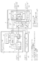
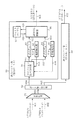
図1は、この発明の実施の形態1によるATMセル転送方式の構成を示すブロック図であり、155.52MHz2ポート入力、155.52MHz2ポート出力で、ウエイトを考慮してATMセルの転送を行うものである。図において、1は、入力ポート0からATMセル101を入力し、ATMセル108を出力する入力ポート0の入力インタフェース部であり、コネクション/出力ポート検出部11,ウエイトテーブル12,ウエイトテーブル制御部(タイプA)14,廃棄処理部17により構成されている。
【0032】
また、図1において、2は、入力ポート1からATMセル201を入力し、ATMセル208を出力する入力ポート1の入力インタフェース部で、図示されていないが、入力ポート0の入力インタフェース部1と同様に、コネクション/出力ポート検出部21,ウエイトテーブル22,ウエイトテーブル制御部(タイプA)24,廃棄処理部27により構成されている。
【0033】
さらに、図1において、3は、入力ポート0の入力インタフェース部1より出力されたATMセル108と、入力ポート1の入力インタフェース部2より出力されたATMセル208を入力して、出力ポート対応にスイッチングを行うATMスイッチ部であり、多重化部31,ポート振り分け部32,出力ポート0の出力バッファ部33,出力ポート1の出力バッファ部34により構成されている。
【0034】
入力インタフェース部1において、コネクション/出力ポート検出部11は、入力ポート0からのATMセル101のVPI/VCIより、コネクションの識別を行ってコネクション情報102を出力し、出力ポートの決定を行って出力ポート番号103を出力すると共に、出力ポート番号103を含んだオーバーヘッドを付与したATMセル104を出力する。
【0035】
ウエイトテーブル12は、初期状態において、接続コネクション毎に契約帯域に対応したATMセル数単位のウエイト値の初期値を格納している。このウエイト値は、各コネクションの帯域の分配量を示している。
【0036】
ウエイトテーブル制御部(タイプA)14は、コネクション/出力ポート検出部11からのコネクション情報102,出力ポート番号103,及びATMスイッチ部3からのバックプレッシャー信号315,316により、ウエイトテーブル12のウエイト値105を読み出して減算し、減算した値106をウエイトテーブル12に格納すると共に、廃棄指示信号107の生成を行う。廃棄処理部17は、ウエイトテーブル制御部(タイプA)14からの廃棄指示信号107によりATMセル104の廃棄を行う。
【0037】
入力ポート1の入力インタフェース部2における図示されていないコネクション/出力ポート検出部21,ウエイトテーブル22,ウエイトテーブル制御部(タイプA)24,廃棄処理部27も、入力ポート0の入力インタフェース部1のコネクション/出力ポート検出部11,ウエイトテーブル12,ウエイトテーブル制御部(タイプA)14,廃棄処理部17と同様の機能を有している。
【0038】
ATMスイッチ部3において、多重化部31は、入力ポート0の入力インタフェース部1より出力されたATMセル108と、入力ポート1の入力インタフェース部2より出力されたATMセル208を入力して、多重化されたATMセル301に変換して出力する。ポート振り分け部32は、多重化されたATMセル301に付与されている出力ポート番号103をもとに、出力ポート対応にATMセル301の振り分けを行い、出力ポート0宛のATMセル311と、出力ポート1宛のATMセル312を出力する。
【0039】
出力ポート0の出力バッファ部33は、出力ポート対応の出力バッファで、出力キュー41とキュー長比較部42により構成されている。出力キュー41は、出力ポート0宛のATMセル311の蓄積を行い、キュー長比較部42は、読み出し制御信号314により出力キュー41に蓄積されたATMセル311の読み出し制御を行い、キュー長(蓄積セル数)313を監視して、キュー長313が所定の閾値を超えた場合に、入力ポート0の入力インタフェース部1のウエイトテーブル制御部(タイプA)14と、入力ポート1の入力インタフェース部2のウエイトテーブル制御部(タイプA)24に、バックプレッシャー信号315を出力する。
【0040】
出力ポート1の出力バッファ部34も、出力ポート0の出力バッファ部33と同様に、図示されていない出力キュー43とキュー長比較部44により構成されており、キュー長比較部44は、出力キュー43に蓄積されたATMセル312の読み出し制御を行い、キュー長を監視して、キュー長が所定の閾値を超えた場合に、入力ポート0の入力インタフェース部1のウエイトテーブル制御部(タイプA)14と、入力ポート1の入力インタフェース部2のウエイトテーブル制御部(タイプA)24に、バックプレッシャー信号316を出力する。
【0041】
次に動作について説明する。
入力ポート0からのATMセル101は、入力インタフェース部1のコネクション/出力ポート検出部11に入力される。コネクション/出力ポート検出部11は、ATMセル101のVPI/VCIを抽出して、VPI/VCI値によるコネクション情報102と、図示しないVPI/VCI単位の出力ポートテーブルより読み出した出力ポート番号103を、ウエイトテーブル制御部(タイプA)14に転送すると共に、出力ポート番号103を含んだオーバーヘッドを付与したATMセル104を廃棄処理部17に転送する。
【0042】
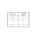
図2はウエイトテーブル12のフォーマットを示す図であり、ウエイトテーブル12には、装置の立ち上げ時等の初期状態では、コネクション単位(VPI/VCI単位)に、契約帯域に対応したATMセル数単位のウエイト値の初期値が設定されている。ウエイトテーブル制御部(タイプA)14は、入力ポート0からのATMセル101がコネクション/出力ポート検出部11に入力され、コネクション/出力ポート検出部11からのVPI/VCI値によるコネクション情報102を入力する毎に、コネクション情報102のVPI/VCI値により、ウエイトテーブル12から対応するコネクションのウエイト値105を読み出す。
【0043】
また、ウエイトテーブル制御部(タイプA)14は、ATMスイッチ部3からの出力ポート対応のバックプレッシャー信号315,316がない場合には、廃棄処理部17に廃棄指示信号107を出力せずに、廃棄処理部17がATMセル104を廃棄せずに、ATMセル108としてATMスイッチ部3に出力するよう制御する。廃棄処理部17は、ウエイトテーブル制御部(タイプA)14からの廃棄指示信号107の有無により、ATMセル104を、ATMスイッチ部3に転送するか、廃棄するかを決定する。
【0044】
入力ポート1の入力インタフェース部2の図示されていないコネクション/出力ポート検出部21,ウエイトテーブル22,ウエイトテーブル制御部(タイプA)24,廃棄処理部27も、入力ポート0の入力インタフェース部1のコネクション/出力ポート検出部11,ウエイトテーブル12,ウエイトテーブル制御部(タイプA)14,廃棄処理部17と同様の動作を行い、廃棄処理部27からATMセル208が出力される。
【0045】
入力インタフェース部1より出力されたATMセル108,入力インタフェース部2より出力されたATMセル208は、ATMスイッチ部3の多重化部31により集線され、各入力ポートにおけるインタフェース速度の2倍の311.04MHzのATMセル301となり、ポート振り分け部32に入力される。ポート振り分け部32は、ATMセル301に付与されているオーバーヘッドの出力ポート番号103に基づき、ATMセル301をATMセル311,312に振り分けて、出力ポート0の出力バッファ部33,出力ポート1の出力バッファ部34の出力キュー41,43にそれぞれ蓄積する。
【0046】
キュー長比較部42は、読み出し制御信号314により、出力キュー41に蓄積されたATMセル311を読み出し、出力ポートの速度である155.52MHzの速度で、出力ポート0宛のATMセル321を出力する。同様に、出力バッファ部34のキュー長比較部44は、読み出し制御信号により、出力キュー43に蓄積されたATMセル312を読み出し、出力ポートの速度である155.52MHzの速度で、出力ポート1宛のATMセル322を出力する。
【0047】
さらに、キュー長比較部42は、あらかじめ所定のウエイト制御動作閾値が設定されており、出力キュー41のATMセル311のキュー長(蓄積セル数)313を監視して、キュー長313がウエイト制御動作閾値を超えた場合に、入力インタフェース部1のウエイトテーブル制御部(タイプA)14と、入力インタフェース部2のウエイトテーブル制御部(タイプA)24に、ウエイト制御動作をさせるための出力ポート0対応のバックプレッシャー信号315を出力する。
【0048】
同様に、キュー長比較部44は、あらかじめ所定のウエイト制御動作閾値が設定されており、出力キュー43のATMセル312のキュー長を監視して、キュー長がウエイト制御動作閾値を超えた場合に、入力インタフェース部1のウエイトテーブル制御部(タイプA)14と、入力インタフェース部2のウエイトテーブル制御部(タイプA)24に、ウエイト制御動作をさせるための出力ポート1対応のバックプレッシャー信号316を出力する。
【0049】
次に、ウエイトテーブル制御部(タイプA)14,24の動作を、ケース別に説明する。
まず、ATMスイッチ部3からバックプレッシャー信号315,316がない場合[ケース(1)]について説明する。
入力ポート0からのATMセル101がコネクション/出力ポート検出部11に入力され、コネクション/出力ポート検出部11からコネクション情報102を入力する毎に、ウエイトテーブル制御部(タイプA)14は、ウエイトテーブル12から読み出したウエイト値105より1を減算し、減算した値をウエイトテーブル12から読み出したコネクションのテーブルに、ウエイト値106として格納する。減算結果がマイナスの場合は0を書き込む。また、ウエイトテーブル制御部(タイプA)14は、廃棄処理部17に廃棄指示信号107を出力せずに、ATMセル104を廃棄しないように制御を行う。
【0050】
ウエイトテーブル12において、全コネクションのウエイト値が0になった場合には、ウエイトテーブル制御部(タイプA)14は、装置の立ち上げ時の初期状態におけるウエイト値の初期値をロードする。ウエイトテーブル制御部(タイプA)24の動作も、ウエイトテーブル制御部(タイプA)14の動作と同様である。
【0051】
次に、ATMスイッチ部3から出力ポート0対応のバックプレッシャー信号315がある場合[ケース(2)]について説明する。
入力ポート0からのATMセル101が、コネクション/出力ポート検出部11に入力され、コネクション/出力ポート検出部11からの出力ポート番号103を入力する毎に、ウエイトテーブル制御部(タイプA)14は、出力ポート番号103と、バックプレッシャー信号315が出力されている出力ポートを比較する。この場合、出力ポート0に出力するATMセルが、ウエイト制御対象のATMセルとなる。
【0052】
出力ポート0宛に出力するATMセルが、コネクション/出力ポート検出部11に入力されると、ウエイトテーブル制御部(タイプA)14は、コネクション/出力ポート検出部11からのコネクション情報102によりウエイトテーブル12から読み出したウエイト値105が1以上であれば、廃棄処理部17に廃棄指示信号107を出力せずに、コネクション/出力ポート検出部11からのATMセル104を廃棄しないように制御し、ウエイトテーブル12から読み出したウエイト値105から1を減算した結果を、ウエイト値106として、読み出したコネクションのテーブルに格納する。
【0053】
読み出したウエイト値105が0の場合には、ウエイトテーブル制御部(タイプA)14は、廃棄処理部17に、ウエイト値105が0となっているコネクションで、出力ポート0宛のATMセルを廃棄するように廃棄指示信号107を出力し、読み出したウエイト値105である0を、ウエイト値106として、読み出したコネクションのテーブルに格納する。廃棄処理部17は、廃棄指示信号107に基づき、ウエイト値105が0となっているコネクションで、出力ポート0宛のATMセルを廃棄する。
【0054】
出力ポート1宛に出力するATMセルが、コネクション/出力ポート検出部11に入力されたときは、ウエイト制御対象のATMセルではないので、上記ケース(1)の場合と同じ動作を行う。
【0055】
ウエイトテーブル制御部(タイプA)24の動作も、ウエイトテーブル制御部(タイプA)14の動作と同じであり、出力ポート0宛に出力するATMセルに対し、上記と同じウエイト制御を行う。
【0056】
次に、ATMスイッチ部3から出力ポート1対応のバックプレッシャー信号316がある場合[ケース(3)]は、制御対象のATMセルが、ケース(2)と逆であり、ウエイトテーブル制御部(タイプA)14,24は、出力ポート1宛に出力するATMセルに対して、上記と同様のウエイト制御を行う。
【0057】
最後に、ATMスイッチ部3から出力ポート0対応、出力ポート1対応のバックプレッシャー信号315,316がある場合[ケース(4)]では、ウエイトテーブル制御部(タイプA)14,24は、出力ポート0宛に出力するATMセルと、出力ポート1宛に出力するATMセルの両方に対して、上記と同様のウエイト制御を行う。
【0058】
なお、この実施の形態では、2ポート入力、2ポート出力の場合を示しているが、nポート入力、nポート出力においても、入力インタフェース部をn個にして、出力バッファ部をn個にすることにより実現可能である。この場合、多重化部31の出力は、155.52MHzのn倍の速度になる。
【0059】
また、この実施の形態では、ウエイトテーブル12における全コネクションのウエイト値が0になった場合に、ウエイト値の初期値のロードを行っているが、ATMスイッチ部3からのバックプレッシャー信号315,316がない間に、ウエイト値の初期値のロードを行うようにしても良い。
【0060】
さらに、所定の時間周期に、ウエイトテーブル12におけるウエイト値の初期値のロードを行うようにしても良い。
【0061】
さらに、ウエイトテーブル12におけるウエイト値の初期値のロードを、初期状態の場合にのみ行い、所定時間周期に、ウエイトテーブル12に残っているウエイト値と、初期状態でロードされるウエイト値の初期値を加算した値を、ウエイトテーブル12にロードするようにしても良い。
【0062】
以上のように、この実施の形態1によれば、入力インタフェース部1,入力インタフェース部2側で、コネクションのウエイトを考慮してATMセルの廃棄制御を行っているので、コネクションが増大しても、ATMスイッチ部3の出力キュー41,43を増設する必要がなく、出力キュー41,43からの出力ポート0宛のATMセル321,出力ポート1宛のATMセル322の読み出し制御を、高速動作させる必要がないという効果が得られる。
【0063】
実施の形態2.
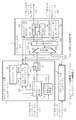
図3は、この発明の実施の形態2によるATMセル転送方式の構成を示すブロック図で、155.52MHz2ポート入力、155.52MHz2ポート出力で、コネクションのウエイトを考慮して、AAL5(ATM AdaptionLayer 5)でATMセル化されたIPパケットを転送するものである。図において、1は、入力ポート0からAAL5でATMセル化されたIPパケット111を入力して、ATMセル108を出力する入力ポート0の入力インタフェース部であり、コネクション/出力ポート検出部11,ウエイトテーブル13,ウエイトテーブル制御部(タイプB)15,廃棄処理部17,フレーム先頭セル判断部18により構成されている。
【0064】
また、図3において、2は、入力ポート1からAAL5でATMセル化されたIPパケット211を入力し、ATMセル208を出力する入力ポート1の入力インタフェース部であり、図示されていないが、入力ポート0の入力インタフェース部1と同様に、コネクション/出力ポート検出部21,ウエイトテーブル23,ウエイトテーブル制御部(タイプB)25,廃棄処理部27,フレーム先頭セル判断部28により構成されている。
【0065】
さらに、図3において、3は、入力ポート0の入力インタフェース部1より出力されたATMセル108と、入力ポート1の入力インタフェース部2より出力されたATMセル208を入力し、出力ポート対応にATMセルのスイッチングを行い、出力ポート0宛のATM化されたIPパケット331と、出力ポート1宛のATM化されたIPパケット332を出力するATMスイッチ部であり、実施の形態1の図1と同様に、多重化部31,ポート振り分け部32,出力ポート0の出力バッファ部33,出力ポート1の出力バッファ部34により構成されている。
【0066】
入力インタフェース部1において、コネクション/出力ポート検出部11は、AAL5でATMセル化されたIPパケット111のATMセルのVPI/VCIより、コネクションの識別を行ってコネクション情報102を出力し、出力ポートの決定を行って出力ポート番号103を出力すると共に、出力ポート番号103を含んだオーバーヘッドを付与したATMセル104を出力する。フレーム先頭セル判断部18は、ATMセル化されたIPパケット111を入力して、ATMセル化されたIPパケットの先頭セルを識別し、先頭セル識別信号112を出力する。
【0067】
ウエイトテーブル13は、初期状態において、接続コネクション毎に契約帯域に対応したIPパケット数単位のウエイト値の初期値を格納している。このウエイト値は、各コネクションの帯域の分配量を示している。
【0068】
ウエイトテーブル制御部(タイプB)15は、コネクション/出力ポート検出部11からのコネクション情報102,出力ポート番号103,ATMスイッチ部3からのバックプレッシャー信号315,316,及びフレーム先頭セル判断部18からの先頭セル識別信号112により、ウエイトテーブル13のウエイト値105を読み出して減算し、減算した値106をウエイトテーブル13に格納すると共に、廃棄指示信号107の生成を行う。廃棄処理部17は、ウエイトテーブル制御部(タイプB)15からの廃棄指示信号107により、ATMセル104の廃棄処理を行う。
【0069】
入力ポート1の入力インタフェース部2の図示されていないコネクション/出力ポート検出部21,ウエイトテーブル23,ウエイトテーブル制御部(タイプB)25,廃棄処理部27,フレーム先頭セル判断部28も、入力ポート0の入力インタフェース部1のコネクション/出力ポート検出部11,ウエイトテーブル13,ウエイトテーブル制御部(タイプB)15,廃棄処理部17,フレーム先頭セル判断部18と同様の機能を有している。
【0070】
ATMスイッチ部3において、多重化部31は、入力ポート0の入力インタフェース部1より出力されたATMセル108と、入力ポート1の入力インタフェース部2より出力されたATMセル208を入力して、多重化されたATMセル301に変換して出力する。ポート振り分け部32は、多重化されたATMセル301に付与されている出力ポート情報103をもとに、出力ポート対応にATMセル301の振り分けを行い、出力ポート0宛のATMセル311と、出力ポート1宛のATMセル312を出力する。
【0071】
出力ポート0の出力バッファ部33は、出力ポート0対応の出力バッファであり、出力キュー41とキュー長比較部42により構成されている。出力キュー41は、出力ポート0対応にATMセル311の蓄積を行い、キュー長比較部42は、読み出し制御信号314により出力キュー41に蓄積されたATMセル311の読み出し制御を行い、キュー長(蓄積セル数)313を監視して、キュー長313が所定の閾値を超えた場合に、入力ポート0の入力インタフェース部1のウエイトテーブル制御部(タイプB)15と、入力ポート1の入力インタフェース部2のウエイトテーブル制御部(タイプB)25に、バックプレッシャー信号315を出力する。
【0072】
出力ポート1の出力バッファ部34も、出力ポート0の出力バッファ部33と同様に、図示されていない出力キュー43とキュー長比較部44により構成されており、キュー長比較部44は、出力キュー43に蓄積されたATMセル312の読み出し制御を行い、キュー長を監視して、キュー長が所定の閾値を超えた場合に、入力ポート0の入力インタフェース部1のウエイトテーブル制御部(タイプB)15と、入力ポート1の入力インタフェース部2のウエイトテーブル制御部(タイプB)25に、バックプレッシャー信号316を出力する。
【0073】
次に動作について説明する。
入力ポート0からのAAL5でATMセル化されたIPパケット111は、入力インタフェース部1のコネクション/出力ポート検出部11,フレーム先頭セル判断部18に入力される。コネクション/出力ポート検出部11は、入力されたATMセル化されたIPパケット111のATMセルのVPI/VCIを抽出して、VPI/VCI値であるコネクション情報102と、図示しないVPI/VCI単位の出力ポートテーブルより読み出した出力ポート番号103を、ウエイトテーブル制御部(タイプB)15に転送すると共に、出力ポート番号103を含んだオーバーヘッドを付与したATMセル104を廃棄処理部17に転送する。
【0074】
フレーム先頭セル判断部18は、AAL5でATMセル化されたIPパケット111より、IPパケットの先頭セルを判断し、先頭セル識別信号112をウエイトテーブル制御部(タイプB)15に転送する。
【0075】
ウエイトテーブル13は、初期状態では、コネクション単位(VPI/VCI単位)に、契約帯域に対応したIPパケット数単位のウエイト値の初期値が設定されており、図2に示すウエイトテーブル12と同様な内容が格納されている。ウエイトテーブル制御部(タイプB)15は、フレーム先頭セル判断部18より先頭セル識別信号112が入力される毎に、コネクション/出力ポート検出部11から転送されたコネクション情報102のVPI/VCI値により、ウエイトテーブル13から対応するコネクションのIPパケット数単位のウエイト値105を読み出す。
【0076】
また、ウエイトテーブル制御部(タイプB)15は、ATMスイッチ部3から出力ポート対応のバックプレッシャー信号315,316がない場合には、廃棄処理部17に廃棄指示信号107を出力せずに、廃棄処理部17が後続セルを含めたATMセル104を廃棄せずに、ATMセル108としてATMスイッチ部3に出力するよう制御する。廃棄処理部17は、ウエイトテーブル制御部(タイプB)15からの廃棄指示信号107の有無により、ATMセル104をATMスイッチ部3に転送するか、廃棄するかを決定する。
【0077】
入力ポート1の入力インタフェース部2の図示されていないコネクション/出力ポート検出部21,ウエイトテーブル23,ウエイトテーブル制御部(タイプB)25,廃棄処理部27,フレーム先頭セル判断部28も、入力ポート0の入力インタフェース部1のコネクション/出力ポート検出部11,ウエイトテーブル13,ウエイトテーブル制御部(タイプB)15,廃棄処理部17,フレーム先頭セル判断部18と同様の動作を行い、廃棄処理部27からATMセル208が出力される。
【0078】
入力インタフェース部1より出力されたATMセル108,入力インタフェース部2より出力されたATMセル208は、多重化部31により集線され、各入力ポートにおけるインタフェース速度の2倍の311.04MHzのATMセル301となり、ポート振り分け部32に入力される。ポート振り分け部32は、ATMセル301に付与されているオーバーヘッドの出力ポート番号103に基づき、ATMセル301をATMセル311,312に振り分けて、出力ポート0の出力バッファ部33の出力キュー41,出力ポート1の出力バッファ部34の出力キュー43にそれぞれ蓄積する。
【0079】
キュー長比較部42は、読み出し制御信号314により、出力キュー41に蓄積されたATMセル311を読み出して、出力ポートの速度である155.52MHzの速度で、出力ポート0宛のATMセル化されたIPパケット331を出力する。同様に、出力バッファ部34のキュー長比較部44は、読み出し制御信号により、出力キュー43に蓄積されたATMセル312を読み出し、出力ポートの速度である155.52MHzの速度で、出力ポート1宛のATMセル化されたIPパケット322を出力する。
【0080】
さらに、キュー長比較部42は、あらかじめ所定のウエイト制御動作閾値が設定されており、出力キュー41のATMセル311のキュー長(蓄積セル数)313を監視して、キュー長313がウエイト制御動作閾値を超えた場合に、入力インタフェース部1のウエイトテーブル制御部(タイプB)15と、入力インタフェース部2のウエイトテーブル制御部(タイプB)25に、ウエイト制御動作をさせるための出力ポート0対応のバックプレッシャー信号315を出力する。
【0081】
同様に、キュー長比較部44は、あらかじめ所定のウエイト制御動作閾値が設定されており、出力キュー43のATMセル312のキュー長を監視して、キュー長がウエイト制御動作閾値を超えた場合に、入力インタフェース部1のウエイトテーブル制御部(タイプB)15と、入力インタフェース部2のウエイトテーブル制御部(タイプB)25に、ウエイト制御動作をさせるための出力ポート1対応のバックプレッシャー信号316を出力する。
【0082】
次に、ウエイトテーブル制御部(タイプB)15,25の動作を、ケース別に説明する。
まず、ATMスイッチ部3からバックプレッシャー信号315,316のない場合[ケース(5)]について説明する。
フレーム先頭セル判断部18から先頭セル識別信号112が入力される毎に、ウエイトテーブル制御部(タイプB)15は、ウエイトテーブル13から読み出したウエイト値105より1を減算し、減算した値をウエイトテーブル13から読み出したコネクションのテーブルに、ウエイト値106として書き込む。減算結果がマイナスの場合は0を書き込む。また、ウエイトテーブル制御部(タイプB)15は、廃棄処理部17に廃棄指示信号107を出力せずに、後続セルを含めたATMセル104を廃棄しないように制御を行う。
【0083】
ウエイトテーブル13において、全コネクションのウエイト値が0になった場合には、ウエイトテーブル制御部(タイプB)15は、装置の立ち上げ時の初期状態におけるIPパケット単位のウエイト値の初期値をロードする。ウエイトテーブル制御部(タイプB)25の動作も、ウエイトテーブル制御部(タイプB)15の動作と同様である。
【0084】
次に、ATMスイッチ部3から出力ポート0対応のバックプレッシャー信号315がある場合[ケース(6)]について説明する。
フレーム先頭セル判断部18から先頭セル識別信号112が入力される毎に、ウエイトテーブル制御部(タイプB)15は、コネクション/出力ポート検出部11より転送される出力ポート番号103と、バックプレッシャー信号315が出力されている出力ポートを比較する。この場合、出力ポート0宛に出力するIPパケットが、ウエイト制御対象のIPパケットとなる。
【0085】
フレーム先頭セル判断部18から先頭セル識別信号112が入力されると、ウエイトテーブル制御部(タイプB)15は、コネクション/出力ポート検出部11からのコネクション情報102によりウエイトテーブル13から読み出したウエイト値105が1以上であれば、廃棄処理部17に廃棄指示信号107を出力せずに、後続セルを含めたATMセル104を廃棄しないように制御し、ウエイトテーブル13から読み出したウエイト値105から1を減算した結果を、ウエイト値106として、読み出したコネクションのテーブルに格納する。
【0086】
読み出したウエイト値105が0の場合には、ウエイトテーブル制御部(タイプB)15は、廃棄処理部17に、ウエイト値105が0のコネクションで、出力ポート0宛の後続セルを含めたATMセル104を、IPパケット単位で廃棄するように廃棄指示信号107を出力し、読み出したウエイト値105である0を、ウエイト値106として、読み出したコネクションのテーブルに格納する。廃棄処理部17は、廃棄指示信号107に基づき、ウエイト値105が0のコネクションで、出力ポート0宛のATMセル104を、IPパケット単位で廃棄する。
【0087】
出力ポート1宛に出力するATMセル化されたIPパケットが、コネクション/出力ポート検出部11に入力されたときは、ウエイト制御対象のIPパケットではないので、上記ケース(5)の場合と同じ動作を行う。
【0088】
ウエイトテーブル制御部(タイプB)25の動作も、ウエイトテーブル制御部(タイプB)15の動作と同じであり、出力ポート0宛に出力するATMセル化されたIPパケットに対し、上記と同じウエイト制御を行う。
【0089】
次に、ATMスイッチ部3から出力ポート1対応のバックプレッシャー信号316がある場合[ケース(7)]は、制御対象のIPパケットが、ケース(6)と逆であり、ウエイトテーブル制御部(タイプB)15,25は、出力ポート1宛に出力するATM化されたIPパケットに対して、上記と同様のウエイト制御を行う。
【0090】
最後に、ATMスイッチ部3から出力ポート0対応、出力ポート1対応のバックプレッシャー信号315,316がある場合[ケース(8)]では、ウエイトテーブル制御部(タイプB)15,25は、出力ポート0宛に出力するATM化されたIPパケットと、出力ポート1宛に出力するATMセル化されたIPパケットの両方に対して、上記と同様のウエイト制御を行う。
【0091】
なお、この実施の形態では、2ポート入力、2ポート出力の場合を示しているが、nポート入力、nポート出力においても、入力インタフェース部をn個に、出力バッファ部をn個にすることにより実現可能である。この場合、多重化部31の出力は155.52MHzのn倍の速度になる。
【0092】
また、この実施の形態では、コネクション/出力ポート検出部11が、ATMセルのVPI/VCI値より出力ポート番号103を検出しているが、AAL5でATMセル化されたIPパケット111の宛先IPアドレスより、出力ポート番号103を検出することも可能である。
【0093】
また、この実施の形態では、ウエイトテーブル13における全コネクションのウエイト値が0になった場合に、ウエイト値の初期値のロードを行っているが、ATMスイッチ部3からのバックプレッシャー信号315,316がない間に、ウエイト値の初期値のロードを行うようにしても良い。
【0094】
さらに、所定の時間周期に、ウエイトテーブル13におけるウエイト値の初期値のロードを行うようにしても良い。
【0095】
さらに、ウエイトテーブル13におけるウエイト値の初期値のロードを、初期状態の場合にのみ行い、所定時間周期に、ウエイトテーブル13に残っているウエイト値と、初期状態でロードされるウエイト値の初期値を加算した値を、ウエイトテーブル13にロードするようにしても良い。
【0096】
さらに、この実施の形態では、ATM化されたIPパケットを伝送するものとしたが、伝送するフレームとしてIPパケットに限るものではなく、LANエミュレーションフレーム等の他のフレームでも良い。
【0097】
以上のように、この実施の形態2によれば、入力インタフェース部1,入力インタフェース部2側で、コネクションのウエイトを考慮してATMセル化されたIPパケットの廃棄制御を行っているので、コネクションが増大しても、ATMスイッチ部3の出力キュー41,43を増設する必要がなく、出力キュー41からの出力ポート0宛のATMセル化されたIPパケット331,出力キュー43からの出力ポート1宛のATMセル化されたIPパケット332の読み出し制御を、高速動作させる必要がないという効果が得られる。
【0098】
実施の形態3.
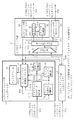
図4は、この発明の実施の形態3によるATMセル転送方式の構成を示すブロック図であり、155.52MHz2ポート入力、155.52MHz2ポート出力で、コネクションのウエイトを考慮してAAL5でATMセル化されたIPパケットを転送するものである。図において、1は、入力ポート0からAAL5でATMセル化されたIPパケット111を入力して、ATMセル108を出力する入力ポート0の入力インタフェース部であり、コネクション/出力ポート検出部11,ウエイトテーブル12,ウエイトテーブル制御部(タイプC)16,廃棄処理部17,フレーム先頭セル判断部18,フレームレングス抽出部19により構成されている。
【0099】
また、図4において、2は、入力ポート1からAAL5でATMセル化されたIPパケット211を入力し、ATMセル208を出力する入力ポート1の入力インタフェース部であり、図示されていないが、入力ポート0の入力インタフェース部1と同様に、コネクション/出力ポート検出部21,ウエイトテーブル22,ウエイトテーブル制御部(タイプC)26,廃棄処理部27,フレーム先頭セル判断部28,フレームレングス抽出部29により構成されている。
【0100】
さらに、図4において、3は、入力ポート0の入力インタフェース部1より出力されたATMセル108と、入力ポート1の入力インタフェース部2より出力されたATMセル208を入力し、出力ポート対応にATMセルのスイッチングを行い、出力ポート0宛のATMセル化されたIPパケット331と、出力ポート1宛のATMセル化されたIPパケット332を出力するATMスイッチ部であり、実施の形態2の図3と同様の構成になっている。
【0101】
入力インタフェース部1において、コネクション/出力ポート検出部11と、フレーム先頭セル判断部18は、実施の形態2の図3におけるコネクション/出力ポート検出部11と、フレーム先頭セル判断部18と同等である。フレームレングス抽出部19は、フレーム先頭セル判断部18からの先頭セル識別信号112により、コネクション/出力ポート検出部11から出力されたATMセル104の先頭のATMセルにおけるペイロード(ユーザ情報)内のフレームレングス113を抽出する。
【0102】
ウエイトテーブル12は、実施の形態1の図2に示すウエイトテーブル12と同じであり、初期状態において、接続コネクション毎に契約帯域に対応したATMセル数単位のウエイト値の初期値を格納している。
【0103】
ウエイトテーブル制御部(タイプC)16は、コネクション/出力ポート検出部11からのコネクション情報102,出力ポート番号103,ATMスイッチ部3からのバックプレッシャー信号315,316,フレーム先頭セル判断部18からの先頭セル識別信号112,及びフレームレングス抽出部19からのフレームレングス113により、IPパケットのATMセル数を計算し、ウエイトテーブル12のウエイト値105を読み出して、計算したIPパケットのATMセル数を減算し、減算した値106をウエイトテーブル12に格納すると共に、廃棄指示信号107の生成を行う。廃棄処理部17は、ウエイトテーブル制御部(タイプC)16からの廃棄指示信号107により、ATMセル104の廃棄処理を行う。
【0104】
入力ポート1の入力インタフェース部2の図示されていないコネクション/出力ポート検出部21,ウエイトテーブル22,ウエイトテーブル制御部(タイプC)26,廃棄処理部27,フレーム先頭セル判断部28,フレームレングス抽出部29も、入力ポート0の入力インタフェース部1のコネクション/出力ポート検出部11,ウエイトテーブル12,ウエイトテーブル制御部(タイプC)16,廃棄処理部17,フレーム先頭セル判断部18,フレームレングス抽出部19と同じ機能を有している。
【0105】
ATMスイッチ部3は、実施の形態2の図3におけるATMスイッチ部3と同じ機能を有している。この実施の形態では、キュー長比較部42,44からのバックプレッシャー信号315,316は、入力ポート0の入力インタフェース部1のウエイトテーブル制御部(タイプC)16と、入力ポート1の入力インタフェース部2のウエイトテーブル制御部(タイプC)26に入力される。
【0106】
次に動作について説明する。
入力ポート0からのAAL5でATMセル化されたIPパケット111は、入力インタフェース部1のコネクション/出力ポート検出部11,フレーム先頭セル判断部18に入力される。コネクション/出力ポート検出部11は、入力されたATMセル化されたIPパケット111のATMセルのVPI/VCIを抽出して、VPI/VCI値であるコネクション情報102と、図示しないVPI/VCI単位の出力ポートテーブルより読み出した出力ポート番号103を、ウエイトテーブル制御部(タイプC)16に転送すると共に、出力ポート番号103を含んだオーバーヘッドを付与したATMセル104を廃棄処理部17とフレームレングス抽出部19に転送する。
【0107】
フレーム先頭セル判断部18は、AAL5でATMセル化されたIPパケット111より、IPパケットの先頭セルを判断して、先頭セル識別信号112をウエイトテーブル制御部(タイプC)16とフレームレングス抽出部19に転送する。
【0108】
フレームレングス抽出部19は、フレーム先頭セル判断部18から先頭セル識別信号112が入力されると、コネクション/出力ポート検出部11より入力されるATMセル104は、IPパケットの先頭セルであるので、ペイロードに入っているフレームレングス113を抽出し、ウエイトテーブル制御部(タイプC)16に転送する。
【0109】
ウエイトテーブル制御部(タイプC)16は、フレーム先頭セル判断部18より、先頭セル識別信号112が入力される毎に、コネクション/出力ポート検出部11から転送されたコネクション情報102のVPI/VCI値により、ウエイトテーブル12から対応するコネクションのATMセル数単位のウエイト値105を読み出す。
【0110】
また、ウエイトテーブル制御部(タイプC)16は、フレーム先頭セル判断部18から先頭セル識別信号112が入力される毎に、フレームレングス抽出部19より転送されるフレームレングス113より、IPパケットのATMセル数を計算し、ウエイトテーブル12より読み出した対応するコネクションのATMセル数単位のウエイト値105から、計算したIPパケットのATMセル数を減算し、減算した値を読み出したコネクションのテーブルに、ウエイト値106として書き込む。
【0111】
さらに、ウエイトテーブル制御部(タイプC)16は、ATMスイッチ部3からの出力ポート対応のバックプレッシャー信号315,316のない場合には、廃棄処理部17に廃棄指示信号107を出力せずに、廃棄処理部17が後続セルを含めたATMセル104を廃棄をせずに、ATMセル108としてATMスイッチ部3に出力するよう制御する。廃棄処理部17は、廃棄指示信号107の有無により、ATMセル104をATMスイッチ部3に転送するか、廃棄するかを決定する。
【0112】
入力ポート1の入力インタフェース部2の図示されていないコネクション/出力ポート検出部21,ウエイトテーブル22,ウエイトテーブル制御部(タイプC)26,廃棄処理部27,フレーム先頭セル判断部28,フレームレングス抽出部29も、入力ポート0の入力インタフェース部1のコネクション/出力ポート検出部11,ウエイトテーブル12,ウエイトテーブル制御部(タイプC)16,廃棄処理部17,フレーム先頭セル判断部18,フレームレングス抽出部19と同様の動作を行い、廃棄処理部27からATMセル208が出力される。
【0113】
ATMスイッチ部3に入力されたATMセル108,208は、実施の形態2と同様に処理されて、出力ポート0宛のATMセル化されたIPパケット331と、出力ポート1宛のATMセル化されたIPパケット332が出力される。
【0114】
また、出力キュー41,43に蓄積されているATMセル311,312のキュー長が所定のウエイト制御動作閾値を超えた場合に、ATMスイッチ3は、入力インタフェース部1のウエイトテーブル制御部(タイプC)16と、入力インタフェース部2のウエイトテーブル制御部(タイプC)26に、ウエイト制御動作をさせるための出力ポート対応のバックプレッシャー信号315,316を出力する。
【0115】
次に、ウエイトテーブル制御部(タイプC)16,26の動作を、ケース別に説明する。
まず、ATMスイッチ部3からバックプレッシャー信号315,316がない場合[ケース(9)]について説明する。
ウエイトテーブル制御部(タイプC)16は、フレーム先頭セル判断部18から先頭セル識別信号112が入力される毎に、ウエイトテーブル12から読み出したウエイト値105から、フレームレングス抽出部19より転送されるフレームレングス113より計算したIPパケットのATMセル数を減算し、その値をウエイトテーブル12から読み出したコネクションのテーブルに、ウエイト値106として書き込む。減算結果がマイナスの場合は0を書き込む。また、廃棄処理部17に廃棄指示信号107を出力せずに、後続セルを含めたATMセル104を廃棄しないように制御を行う。
【0116】
ウエイトテーブル制御部(タイプC)16は、ウエイトテーブル12に、所定時間周期で、装置の立ち上げ時の初期状態におけるATM数単位のウエイト値の初期値をロードする。ウエイトテーブル制御部(タイプC)26の動作も、ウエイトテーブル制御部(タイプC)16の動作と同様である。
【0117】
次に、ATMスイッチ部3から出力ポート0対応のバックプレッシャー信号315がある場合[ケース(10)]について説明する。
フレーム先頭セル判断部18から先頭セル識別信号112が入力される毎に、ウエイトテーブル制御部(タイプC)16は、コネクション/出力ポート検出部11より転送される出力ポート番号103と、バックプレッシャー信号315が出力されている出力ポートを比較する。この場合、出力ポート0宛に出力するATMセル化されたIPパケットが、ウエイト制御対象のIPパケットとなる。
【0118】
フレーム先頭セル判断部18から先頭セル識別信号112が入力されると、ウエイトテーブル制御部(タイプC)16は、コネクション/出力ポート検出部11からのコネクション情報102によりウエイトテーブル12から読み出したウエイト値105から、フレームレングス抽出部19より転送されるフレームレングス113より計算したIPパケットのATMセル数を減算し、減算結果が0以上であれば、廃棄処理部17に廃棄指示信号107を出力せずに、後続セルを含めたATMセル104を廃棄しないように制御し、減算結果をウエイト値106として、読み出したコネクションのテーブルに格納する。
【0119】
減算結果がマイナスの場合は、ウエイトテーブル制御部(タイプC)16は、廃棄処理部17に、減算結果がマイナスになるコネクションで、出力ポート0宛の後続セルを含めたATMセル104を、IPパケット単位で廃棄するよう廃棄指示信号107を出力し、読み出したウエイト値105をウエイト値106として、読み出したコネクションのテーブルに格納する。廃棄処理部17は、廃棄指示信号107に基づき、減算結果がマイナスになるコネクションで、出力ポート0宛の後続セルを含めたATMセル104を、IPパケット単位で廃棄する。
【0120】
出力ポート1宛に出力するATMセル化されたIPパケットが、コネクション/出力ポート検出部11に入力されたときは、ウエイト制御対象のIPパケットではないので、上記ケース(9)の場合と同じ動作を行う。
【0121】
ウエイトテーブル制御部(タイプC)26の動作も、ウエイトテーブル制御部(タイプC)16の動作と同じであり、出力ポート0宛に出力するATM化されたIPパケットに対して、上記と同じウエイト制御を行う。
【0122】
次に、ATMスイッチ3から出力ポート1対応のバックプレッシャー信号316がある場合[ケース11]は、制御対象のIPパケットがケース(10)と逆であり、ウエイトテーブル制御部(タイプC)16,26は、出力ポート1宛に出力するATMセル化されたIPパケットに対して同じウエイト制御を行う。
【0123】
最後に、ATMスイッチ3から出力ポート0対応、出力ポート1対応のバックプレッシャー信号315,316がある場合[ケース12]では、ウエイトテーブル制御部(タイプC)16,26は、出力ポート0に出力するATMセル化されたIPパケットと、出力ポート1に出力するATMセル化されたIPパケットの両方に対して、上記と同様のウエイト制御を行う。
【0124】
なお、この実施の形態では、2ポート入力、2ポート出力の場合を示しているが、nポート入力、nポート出力においても、入力インタフェース部をn個に、出力バッファ部をn個にすることにより実現可能である。この場合、多重化部31の出力は155.52MHzのn倍の速度になる。
【0125】
また、この実施の形態では、コネクション/出力ポート検出部11で、ATMセルのVPI/VCI値より出力ポート番号103を検出しているが、AAL5でATMセル化されたIPパケット111の宛先IPアドレスより、出力ポート番号103を検出することも可能である。
【0126】
また、この実施の形態では、所定時間周期に、ウエイトテーブル12におけるウエイト値の初期値のロードを行っているが、ATMスイッチ部3からのバックプレッシャー信号315,316がない間に、ウエイト値の初期値のロードを行うようにしても良い。
【0127】
さらに、ウエイトテーブル12におけるウエイト値の初期値ロードを、初期状態の場合にのみ行い、所定時間周期に、ウエイトテーブル12に残っているウエイト値と、初期状態でロードされるウエイト値の初期値を加算した値を、ウエイトテーブル12にロードするようにしても良い。
【0128】
さらに、この実施の形態では、ATM化されたIPパケットを伝送するものとしたが、伝送するフレームとしてIPパケットに限るものではなく、LANエミュレーションフレーム等の他のフレームでも良い。
【0129】
以上のように、この実施の形態3によれば、入力インタフェース部1,入力インタフェース部2側で、コネクションのウエイトを考慮してATMセル化されたIPパケットの廃棄制御を行っているので、コネクションが増大しても、ATMスイッチ部3の出力キュー41,43を増設する必要がなく、出力キュー41からの出力ポート0宛のATMセル化されたIPパケット331,出力キュー43からの出力ポート1宛のATMセル化されたIPパケット332の読み出し制御を、高速動作させる必要がないという効果が得られる。
【0130】
【発明の効果】
以上のように、この発明によれば、ATMスイッチ部が、出力ポート対応に振り分けて蓄積されたATMセルの蓄積セル数を監視し、所定の閾値を超えた場合に、出力ポート対応のバックプレッシャー信号を出力し、入力インタフェース部が、ATMセルの入力に応じてコネクション毎のATMセル数単位の帯域の分配量を管理し、バックプレッシャー信号とコネクション毎のATMセル数単位の帯域の分配量に基づき、入力されたATMセルの廃棄制御を行うことにより、コネクションが増大しても、ATMスイッチ部の出力キューを増設する必要がなく、出力キューからの出力ポート宛のATMセルの読み出し制御を、高速動作させる必要がないという効果がある。
【0131】
この発明によれば、ATMスイッチ部が、出力ポート対応に振り分けて蓄積されたATMセルの蓄積セル数を監視し、所定の閾値を超えた場合に、出力ポート対応のバックプレッシャー信号を出力し、入力インタフェース部が、入力ポートから入力されたフレームにおけるATMセルの先頭セルを識別し、先頭セルの入力に応じてコネクション毎のフレーム数単位の帯域の分配量を管理し、バックプレッシャー信号とコネクション毎のフレーム数単位の帯域の分配量に基づき、入力されたフレームにおけるATMセルの廃棄制御を行うことにより、コネクションが増大しても、ATMスイッチ部の出力キューを増設する必要がなく、出力キューからの出力ポート宛のATMセル化されたフレームの読み出し制御を、高速動作させる必要がないという効果がある。
【0132】
この発明によれば、ATMスイッチ部が、出力ポート対応に振り分けて蓄積されたATMセルの蓄積セル数を監視し、所定の閾値を超えた場合に、出力ポート対応のバックプレッシャー信号を出力し、入力インタフェース部が、入力ポートから入力されたフレームにおけるATMセルの先頭セルを識別し、先頭セルに格納されているフレームレングスを抽出し、このフレームレングスよりフレームにおけるATMセル数を算出し、先頭セルの入力に応じて、算出したフレームのATMセル数に基づき、コネクション毎のATMセル数単位の帯域の分配量を管理し、バックプレッシャー信号とコネクション毎のフレーム数単位の帯域の分配量に基づき、入力されたフレームにおけるATMセルの廃棄制御を行うことにより、コネクションが増大しても、ATMスイッチ部の出力キューを増設する必要がなく、出力キューからの出力ポート宛のATMセル化されたフレームの読み出し制御を、高速動作させる必要がないという効果がある。
【図面の簡単な説明】
【図1】 この発明の実施の形態1によるATMセル転送方式の構成を示すブロック図である。
【図2】 この発明の実施の形態1によるウエイトテーブルのフォーマットを示す図である。
【図3】 この発明の実施の形態2によるATMセル転送方式の構成を示すブロック図である。
【図4】 この発明の実施の形態3によるATMセル転送方式の構成を示すブロック図である。
【図5】 従来のATMセル転送方式の構成を示すブロック図である。
【符号の説明】
1,2 入力インタフェース部、3 ATMスイッチ部、11 コネクション/出力ポート検出部、12,13 ウエイトテーブル、14 ウエイトテーブル制御部(タイプA)[ウエイトテーブル制御部]、15 ウエイトテーブル制御部(タイプB)[ウエイトテーブル制御部]、16 ウエイトテーブル制御部(タイプC)[ウエイトテーブル制御部]、17 廃棄処理部、18 フレーム先頭セル判断部、19 フレームレングス抽出部、31 多重化部、32 ポート振り分け部、41 出力キュー、42 キュー長比較部、101,104,108,201,208,301,311,312,321,322 ATMセル、102 コネクション情報、103 出力ポート番号、105,106 ウエイト値、107 廃棄指示信号、111,211,331,332 ATM化されたIPパケット、112 先頭セル識別信号、113 フレームレングス、313 キュー長(蓄積セル数)、315,316 バックプレッシャー信号。[0001]
BACKGROUND OF THE INVENTION
The present invention relates to an ATM cell transfer system that performs fair distribution of a residual bandwidth in connection units.
[0002]
[Prior art]
FIG. 5 shows the document IEEE JSAC, vol. 9, Oct. A block diagram showing the configuration of a block diagram of a conventional ATM (Asynchronous Transfer Mode) block transfer system shown in 1991 “Weighted Round-robin Cell Multiplexing in a General-purpose ATM Switch Chip”. Here, a case of 155.52
[0003]
In FIG. 5,
[0004]
In FIG. 5,
[0005]
In the
[0006]
The
[0007]
In the initial state, the weight table 97 stores an initial value of the weight value in units of ATM cells corresponding to the contracted bandwidth for each connection, and this weight value indicates the distribution amount of the bandwidth of each connection.
[0008]
Next, the operation will be described.
Here, the
[0009]
The
[0010]
When there is an entry in the
[0011]
Further, in the wait table 97, when the weight value of all connections becomes 0, or when the
[0012]
In this way, when the
[0013]
The operation of the output buffer unit (output port 1) 84 is the same as that of the output buffer unit (output port 0) 83.
[0014]
[Problems to be solved by the invention]
Since the conventional ATM cell transfer system is configured as described above, the
[0015]
Further, the
[0016]
The present invention has been made to solve the above-described problems. Even if the number of connections increases, an increase in the output queue is suppressed, and an ATM cell that does not require a high-speed operation for reading an ATM cell from the output queue. The purpose is to obtain a transfer method.
[0017]
[Means for Solving the Problems]
The ATM cell transfer system according to the present invention corresponds to the input port that inputs the ATM cell from the input port, identifies the connection connection, determines the output port, and outputs the ATM cell assigned the output port number. An input interface unit and each ATM cell output from the input interface unit are input, sorted according to the output port number and stored according to the output port number, and the stored ATM cell is output corresponding to the output port The ATM switch unit monitors the number of ATM cells stored and distributed in correspondence with the output port, and when a predetermined threshold is exceeded, the back pressure corresponding to the output port is detected. The input interface unit outputs the signal according to the input of the ATM cell. The amount of distribution of ATM cells in units of ATM cells is managed, and discard control of the input ATM cells is performed based on the amount of bandwidth distribution in units of ATM cells for each connection. is there.
[0018]
In the ATM cell transfer system according to the present invention, the ATM switch unit multiplexes each ATM cell output from the input interface unit corresponding to the input port, and the ATM cell multiplexed by the multiplexing unit. Are assigned to the output port based on the assigned output port number, the ATM cell distributed by the port assignment unit is stored in the output queue, and the output queue is stored in the output queue. Queue length for reading out and outputting the ATM cell corresponding to the output port, monitoring the number of accumulated ATM cells, and outputting a back pressure signal corresponding to the output port when a predetermined threshold value is exceeded A comparison unit, and the input interface unit supports the contracted bandwidth for each connection in the initial state. A weight table that stores an initial value of a weight value indicating the distribution amount of a band in units of the number of ATM cells, an ATM cell is input from the input port, a connection connection is identified, connection information is output, and an output port And output the output port number and output the ATM cell to which the output port number is assigned. The connection / output port detection unit outputs the weight based on the connection information output from the connection / output port detection unit. When the weight value in the number of ATM cells of the connection stored in the table is read and the read weight value indicates that there is a distribution amount of the bandwidth of the connection, the read weight value is decreased to The weight value stored in the weight table and read When there is no connection bandwidth distribution amount and a back pressure signal is output from the queue length comparison unit, the read weight value is stored in the weight table, and the connection / output port detection is performed. A weight table control unit that outputs a discard instruction signal instructing to discard the ATM cell addressed to the output port from which the back pressure signal is output, with reference to the output port number output from the unit, and the weight table control When there is no discard instruction signal from the unit, the ATM cell output from the connection / output port detection unit is output to the multiplexing unit, and when there is the discard instruction signal, from the connection / output port detection unit A discard processing unit for discarding the output ATM cell based on the discard instruction signal; It is a thing.
[0019]
In the ATM cell transfer system according to the present invention, when the weight value stored in the weight table indicates that there is no bandwidth distribution amount for all connections, the weight table control unit supports the contract bandwidth for each connection. The initial value of the weight value in units of the number of ATM cells is loaded into the weight table.
[0020]
In the ATM cell transfer system according to the present invention, the frame converted to ATM cell by AAL5 is input from the input port, the connection connection of the ATM cell in the frame is identified, the output port is determined, and the output port number is given. Input the ATM cell output from the input interface unit corresponding to the input port for outputting the ATM cell and the ATM cell output from the input interface unit, and distribute and store the ATM cell corresponding to the output port based on the output port number. And an ATM switch unit that outputs ATM cells corresponding to the output ports. The ATM switch unit monitors the number of accumulated ATM cells allocated to the output ports and sets a predetermined threshold value. If it exceeds, output a back pressure signal corresponding to the output port. A face unit that identifies a leading cell of an ATM cell in a frame input from the input port, manages a distribution amount of a band in units of frames for each connection according to the input of the leading cell, and the back pressure signal And discard control of ATM cells in the input frame based on the distribution amount of the band in units of frames for each connection.
[0021]
In the ATM cell transfer system according to the present invention, the ATM switch unit multiplexes the ATM cell output from the input interface unit corresponding to the input port, and the ATM cell multiplexed by the multiplexing unit. , A port distribution unit that distributes to the output port based on the assigned output port number, an output queue that stores the ATM cells distributed by the port distribution unit, and the output queue that stores the ATM cell Queue length comparison that reads and outputs ATM cells corresponding to the output port, monitors the number of accumulated ATM cells, and outputs a back pressure signal corresponding to the output port when a predetermined threshold is exceeded And the input interface supports the contracted bandwidth for each connection in the initial state. A weight table storing an initial value of a weight value indicating a distribution amount of a band in units of the number of frames, and an ATM cell in the frame from the input port, identifying a connection connection and outputting connection information; The output port number is determined and the output port number is output, and the connection / output port detection unit for outputting the ATM cell to which the output port number is assigned, and the first cell of the ATM cell in the frame input from the input port are identified. In response to the input of the head cell identification signal, the frame head cell determination unit that outputs the head cell identification signal is stored in the weight table based on the connection information output from the connection / output port detection unit. Read the weight value in units of frames of the above connection and read When the weight value indicates that there is a distribution amount of the bandwidth of the connection, the read weight value is decreased and stored in the weight table, and the read weight value is the distribution amount of the bandwidth of the connection. When the back pressure signal is output from the queue length comparison unit, the read weight value is stored in the weight table, and the output port output from the connection / output port detection unit Referring to the number, a weight table control unit that outputs a discard instruction signal instructing to discard the ATM cell addressed to the output port from which the back pressure signal is output, in units of frames, and from the weight table control unit Connection / output port detection when there is no discard instruction signal The ATM cell output from the connection unit is output to the multiplexing unit, and when there is the discard instruction signal, the ATM cell output from the connection / output port detection unit is converted into the frame unit based on the discard instruction signal. And a disposal unit for disposal.
[0022]
In the ATM cell transfer system according to the present invention, when the weight value stored in the weight table indicates that there is no bandwidth distribution amount for all connections, the weight table control unit supports the contract bandwidth for each connection. The initial value of the weight value in units of the number of frames is loaded into the weight table.
[0023]
In the ATM cell transfer system according to the present invention, the weight table control unit loads the initial value of the weight value in units of the number of frames corresponding to the contract bandwidth for each connection while there is no back pressure signal from the ATM switch. To do.
[0024]
In the ATM cell transfer system according to the present invention, the weight table control unit loads the initial value of the weight value in units of the number of frames corresponding to the contract bandwidth for each connection into the weight table at a predetermined cycle.
[0025]
In the ATM cell transfer system according to the present invention, the weight table control unit obtains the weight value remaining in the weight table at a predetermined cycle and the initial value of the weight value in units of the number of frames corresponding to the contract bandwidth for each connection. It is added and loaded into the weight table.
[0026]
In the ATM cell transfer system according to the present invention, the ATM port is inputted from the input port by AAL5, the connection connection of the ATM cell in the frame is identified, the output port is determined, and the output port number is assigned. An input interface unit corresponding to the input port for outputting a cell, and an ATM cell output from the input interface unit are input, sorted according to the output port based on the output port number, and stored, and the stored ATM And an ATM switch unit that outputs cells corresponding to the output port, the ATM switch unit monitors the number of accumulated ATM cells allocated to the output port and exceeds a predetermined threshold. Output a back pressure signal corresponding to the output port. The source unit identifies the first cell of the ATM cell in the frame input from the input port, extracts the frame length stored in the first cell, and calculates the number of ATM cells in the frame from the frame length. Based on the calculated number of ATM cells in the frame in accordance with the input of the head cell, the bandwidth distribution amount in units of ATM cells for each connection is managed, and the back pressure signal and the number of ATM cells for each connection are managed. Based on the distribution amount of the unit band, discard control of ATM cells in the input frame is performed.
[0027]
In the ATM cell transfer system according to the present invention, the ATM switch unit multiplexes the ATM cell output from the input interface unit corresponding to the input port, and the ATM cell multiplexed by the multiplexing unit. , A port distribution unit that distributes to the output port based on the assigned output port number, an output queue that stores the ATM cells distributed by the port distribution unit, and the output queue that stores the ATM cell Queue length comparison that reads and outputs ATM cells corresponding to the output port, monitors the number of accumulated ATM cells, and outputs a back pressure signal corresponding to the output port when a predetermined threshold is exceeded And the input interface supports the contracted bandwidth for each connection in the initial state. A weight table storing an initial value of a weight value indicating the distribution amount of a band in the number of ATM cells, and an ATM cell in the frame from the input port are input, a connection connection is identified and connection information is output. A connection / output port detector for determining an output port and outputting an output port number and outputting an ATM cell to which the output port number is assigned; and a first cell of the ATM cell in a frame input from the input port. A frame head cell determining unit for identifying and outputting a head cell identifying signal; a frame length extracting unit for extracting a frame length stored in the head cell of the ATM cell identified by the frame head cell determining unit; From the connection / output port detector according to the cell identification signal input Based on the input connection information, the weight value in the number of ATM cells of the connection stored in the weight table is read, and the number of ATM cells of the frame is calculated from the frame length extracted by the frame length extraction unit. When the value obtained by subtracting the calculated number of ATM cells from the read weight value indicates that there is a distribution amount of the bandwidth of the connection, the subtracted value is stored in the weight table and the subtraction is performed. If the obtained value indicates that there is no distribution amount of the bandwidth of the connection and a back pressure signal is output from the queue length comparison unit, the read weight value is stored in the weight table, and the connection / Refer to the output port number output from the output port detector. When there is no weight table control unit for outputting a discard instruction signal for instructing to discard the ATM cell addressed to the output port from which the back pressure signal is output in units of frames, and there is no discard instruction signal from the weight table control unit The ATM cell output from the connection / output port detection unit is output to the multiplexing unit. When the discard instruction signal is present, the ATM cell output from the connection / output port detection unit is discarded. A discard processing unit configured to discard the frame unit based on the instruction signal.
[0028]
In the ATM cell transfer system according to the present invention, the weight table control unit stores the initial value of the weight value in the number of ATM cells corresponding to the contract bandwidth for each connection in the weight table while there is no back pressure signal from the ATM switch. To load.
[0029]
In the ATM cell transfer system according to the present invention, the weight table control unit loads an initial value of the weight value in units of the number of ATM cells corresponding to the contracted bandwidth for each connection into the weight table at a predetermined cycle.
[0030]
In the ATM cell transfer system according to the present invention, the weight table control unit has a predetermined period, a weight value remaining in the weight table, and an initial value of a weight value in units of ATM cells corresponding to a contract bandwidth for each connection. Are added to the weight table and loaded.
[0031]
DETAILED DESCRIPTION OF THE INVENTION
An embodiment of the present invention will be described below.
FIG. 1 is a block diagram showing the configuration of the ATM cell transfer system according to the first embodiment of the present invention, which transfers ATM cells in consideration of the weight with 155.52 MHz 2-port input and 155.52 MHz 2-port output. It is. In the figure,
[0032]
In FIG. 1,
[0033]
Further, in FIG. 1,
[0034]
In the
[0035]
The weight table 12 stores an initial value of a weight value in units of the number of ATM cells corresponding to the contract bandwidth for each connection connection in the initial state. This weight value indicates the distribution amount of the bandwidth of each connection.
[0036]
The weight table control unit (type A) 14 uses the
[0037]
The connection / output port detection unit 21, the weight table 22, the weight table control unit (type A) 24, and the discard processing unit 27 (not shown) in the
[0038]
In the
[0039]
The
[0040]
Similarly to the
[0041]
Next, the operation will be described.
The
[0042]
FIG. 2 is a diagram showing the format of the weight table 12. In the weight table 12, the ATM cell number unit corresponding to the contracted bandwidth in connection units (VPI / VCI units) in the initial state such as when the apparatus is started up. The initial value of the wait value is set. The weight table control unit (type A) 14 receives the
[0043]
The weight table control unit (type A) 14 does not output the discard
[0044]
The connection / output port detection unit 21, weight table 22, weight table control unit (type A) 24, and discard processing unit 27 (not shown) of the
[0045]
The
[0046]
The queue
[0047]
Further, the queue
[0048]
Similarly, the queue length comparison unit 44 has a predetermined weight control operation threshold set in advance, monitors the queue length of the
[0049]
Next, the operation of the weight table control units (type A) 14 and 24 will be described for each case.
First, the case [case (1)] when there is no
Each time the
[0050]
In the weight table 12, when the weight value of all connections becomes 0, the weight table control unit (type A) 14 loads the initial value of the weight value in the initial state when the apparatus is started up. The operation of the weight table control unit (type A) 24 is the same as the operation of the weight table control unit (type A) 14.
[0051]
Next, the case [case (2)] when there is a back pressure signal 315 corresponding to the output port 0 from the
Each time the
[0052]
When an ATM cell output to the output port 0 is input to the connection / output
[0053]
When the read
[0054]
When an ATM cell output to the
[0055]
The operation of the weight table control unit (type A) 24 is the same as the operation of the weight table control unit (type A) 14, and the same weight control as described above is performed for the ATM cell output to the output port 0.
[0056]
Next, when there is a back pressure signal 316 corresponding to the
[0057]
Finally, when there are back pressure signals 315 and 316 corresponding to the output port 0 and the
[0058]
In this embodiment, the case of 2-port input and 2-port output is shown. However, in the case of n-port input and n-port output, n input interface units are provided and n output buffer units are provided. Can be realized. In this case, the output of the multiplexing
[0059]
In this embodiment, when the weight value of all connections in the weight table 12 becomes 0, the initial value of the wait value is loaded. However, the back pressure signals 315 and 316 from the
[0060]
Furthermore, the initial value of the weight value in the weight table 12 may be loaded in a predetermined time period.
[0061]
Furthermore, loading of the initial value of the weight value in the weight table 12 is performed only in the initial state, and the weight value remaining in the weight table 12 and the initial value of the weight value loaded in the initial state in a predetermined time period. A value obtained by adding may be loaded into the weight table 12.
[0062]
As described above, according to the first embodiment, the
[0063]
FIG. 3 is a block diagram showing the configuration of the ATM cell transfer system according to the second embodiment of the present invention, which is 155.52 MHz 2-port input, 155.52 MHz 2-port output, and considering the connection weight, AAL5 (ATM Adaptation Layer 5 ) Is used to transfer an ATM cellized IP packet. In the figure,
[0064]
In FIG. 3,
[0065]
Further, in FIG. 3,
[0066]
In the
[0067]
The weight table 13 stores an initial value of a weight value in units of the number of IP packets corresponding to the contract bandwidth for each connection connection in the initial state. This weight value indicates the distribution amount of the bandwidth of each connection.
[0068]
The weight table control unit (type B) 15 includes
[0069]
A connection / output port detection unit 21, a weight table 23, a weight table control unit (type B) 25, a discard processing unit 27, and a frame head cell determination unit 28 (not shown) of the
[0070]
In the
[0071]
The
[0072]
Similarly to the
[0073]
Next, the operation will be described.
The
[0074]
The frame head
[0075]
In the weight table 13, in the initial state, the initial value of the weight value in units of the number of IP packets corresponding to the contract bandwidth is set in the connection unit (VPI / VCI unit), and is similar to the weight table 12 shown in FIG. The contents are stored. The weight table control unit (type B) 15 uses the VPI / VCI value of the
[0076]
Further, the weight table control unit (type B) 15 does not output the discard
[0077]
A connection / output port detection unit 21, a weight table 23, a weight table control unit (type B) 25, a discard processing unit 27, and a frame head cell determination unit 28 (not shown) of the
[0078]
The
[0079]
The queue
[0080]
Further, the queue
[0081]
Similarly, the queue length comparison unit 44 has a predetermined weight control operation threshold set in advance, monitors the queue length of the
[0082]
Next, operations of the weight table control units (type B) 15 and 25 will be described for each case.
First, the case [case (5)] when there is no
Each time the head
[0083]
In the weight table 13, when the weight value of all connections becomes 0, the weight table control unit (type B) 15 loads the initial value of the weight value in units of IP packets in the initial state when the apparatus is started up. To do. The operation of the weight table control unit (type B) 25 is the same as the operation of the weight table control unit (type B) 15.
[0084]
Next, the case [Case (6)] when there is a back pressure signal 315 corresponding to the output port 0 from the
Each time the head
[0085]
When the head
[0086]
When the read
[0087]
When an ATM cellized IP packet output to the
[0088]
The operation of the weight table control unit (type B) 25 is the same as the operation of the weight table control unit (type B) 15, and the same weight as above is applied to the IP packet converted to ATM cell output to the output port 0. Take control.
[0089]
Next, when there is a back pressure signal 316 corresponding to the
[0090]
Finally, when there are back pressure signals 315 and 316 corresponding to the output port 0 and the
[0091]
In this embodiment, the case of 2-port input and 2-port output is shown. However, in the case of n-port input and n-port output, n input interface units are provided and n output buffer units are provided. Can be realized. In this case, the output of the multiplexing
[0092]
In this embodiment, the connection / output
[0093]
In this embodiment, when the weight value of all connections in the weight table 13 becomes 0, the initial value of the wait value is loaded. However, the back pressure signals 315 and 316 from the
[0094]
Furthermore, the initial value of the weight value in the weight table 13 may be loaded in a predetermined time period.
[0095]
Furthermore, loading of the initial value of the weight value in the weight table 13 is performed only in the initial state, and the weight value remaining in the weight table 13 and the initial value of the weight value loaded in the initial state in a predetermined time period. A value obtained by adding may be loaded into the weight table 13.
[0096]
Furthermore, in this embodiment, an ATM IP packet is transmitted. However, the frame to be transmitted is not limited to an IP packet, and other frames such as a LAN emulation frame may be used.
[0097]
As described above, according to the second embodiment, the
[0098]
FIG. 4 is a block diagram showing the configuration of the ATM cell transfer system according to the third embodiment of the present invention, which is 155.52 MHz 2-port input, 155.52 MHz 2-port output, and converts the ATM cell into AAL5 in consideration of the connection weight. The transferred IP packet is transferred. In the figure,
[0099]
In FIG. 4,
[0100]
Further, in FIG. 4,
[0101]
In the
[0102]
The weight table 12 is the same as the weight table 12 shown in FIG. 2 of the first embodiment, and stores the initial value of the weight value in units of ATM cells corresponding to the contract bandwidth for each connection connection in the initial state. .
[0103]
The weight table control unit (type C) 16 includes
[0104]
Connection / output port detection unit 21, weight table 22, weight table control unit (type C) 26, discard processing unit 27, frame head cell determination unit 28, frame length extraction (not shown) of the
[0105]
The
[0106]
Next, the operation will be described.
The
[0107]
The frame head
[0108]
When the start
[0109]
The weight table control unit (type C) 16 receives the VPI / VCI value of the
[0110]
The weight table control unit (type C) 16 receives the ATM of the IP packet from the
[0111]
Further, the weight table control unit (type C) 16 does not output the discard
[0112]
Connection / output port detection unit 21, weight table 22, weight table control unit (type C) 26, discard processing unit 27, frame head cell determination unit 28, frame length extraction (not shown) of the
[0113]
The
[0114]
Further, when the queue length of the
[0115]
Next, the operation of the weight table control unit (type C) 16, 26 will be described for each case.
First, the case [case (9)] when there is no
The weight table control unit (type C) 16 is transferred from the frame length extraction unit 19 from the
[0116]
The weight table control unit (type C) 16 loads the weight table 12 with the initial value of the weight value in units of the number of ATMs in the initial state when the apparatus is started up at a predetermined time period. The operation of the weight table control unit (type C) 26 is the same as the operation of the weight table control unit (type C) 16.
[0117]
Next, the case [case (10)] when there is a back pressure signal 315 corresponding to the output port 0 from the
Each time the head
[0118]
When the head
[0119]
When the subtraction result is negative, the weight table control unit (type C) 16 sends the
[0120]
When an ATM cellized IP packet to be output to the
[0121]
The operation of the weight table control unit (type C) 26 is the same as that of the weight table control unit (type C) 16, and the same weight as above is applied to the ATM IP packet output to the output port 0. Take control.
[0122]
Next, when there is a back pressure signal 316 corresponding to the
[0123]
Finally, when there are back pressure signals 315 and 316 corresponding to the output port 0 and the
[0124]
In this embodiment, the case of 2-port input and 2-port output is shown. However, in the case of n-port input and n-port output, n input interface units are provided and n output buffer units are provided. Can be realized. In this case, the output of the multiplexing
[0125]
In this embodiment, the connection / output
[0126]
In this embodiment, the initial value of the weight value in the weight table 12 is loaded at a predetermined time period. However, while there is no
[0127]
Further, the initial value of the weight value in the weight table 12 is loaded only in the initial state, and the weight value remaining in the weight table 12 and the initial value of the weight value loaded in the initial state are set in a predetermined time period. The added value may be loaded into the weight table 12.
[0128]
Furthermore, in this embodiment, an ATM IP packet is transmitted. However, the frame to be transmitted is not limited to an IP packet, and other frames such as a LAN emulation frame may be used.
[0129]
As described above, according to the third embodiment, the
[0130]
【The invention's effect】
As described above, according to the present invention, the ATM switch unit monitors the number of stored ATM cells that are allocated and stored in correspondence with the output port, and when the predetermined threshold value is exceeded, the back pressure corresponding to the output port. A signal is output, and the input interface unit manages the distribution amount of the band in units of the ATM cells for each connection according to the input of the ATM cell, and the distribution amount of the band in units of the number of ATM cells for each connection of the back pressure signal. Based on the discard control of the input ATM cell, even if the connection increases, there is no need to increase the output queue of the ATM switch unit, and the ATM cell read control for the output port from the output queue is performed. There is an effect that it is not necessary to operate at high speed.
[0131]
According to the present invention, the ATM switch unit monitors the number of accumulated ATM cells distributed and stored for the output port, and outputs a back pressure signal for the output port when a predetermined threshold value is exceeded. The input interface unit identifies the first cell of the ATM cell in the frame input from the input port, manages the distribution amount of the band in units of the number of frames for each connection according to the input of the first cell, the back pressure signal and each connection By controlling the discarding of ATM cells in the input frame based on the distribution amount of the band in units of the number of frames, it is not necessary to increase the output queue of the ATM switch unit even if the connection is increased. There is no need to operate the ATM cell frame for the output port at high speed. There is an effect that.
[0132]
According to the present invention, the ATM switch unit monitors the number of accumulated ATM cells distributed and stored for the output port, and outputs a back pressure signal for the output port when a predetermined threshold value is exceeded. The input interface unit identifies the first cell of the ATM cell in the frame input from the input port, extracts the frame length stored in the first cell, calculates the number of ATM cells in the frame from this frame length, In accordance with the input, the distribution amount of the bandwidth in units of ATM cells for each connection is managed based on the calculated number of ATM cells in the frame, and based on the distribution amount of bandwidth in units of frames for each back pressure signal and connection, Increases connections by controlling discarding of ATM cells in input frames Also, there is no need to install additional output queues of the ATM switch unit, the read control of the ATM cell frame output directed to the port from the output queue, there is an effect that it is not necessary to operate at high speed.
[Brief description of the drawings]
FIG. 1 is a block diagram showing a configuration of an ATM cell transfer system according to a first embodiment of the present invention.
FIG. 2 is a diagram showing a format of a weight table according to the first embodiment of the present invention.
FIG. 3 is a block diagram showing a configuration of an ATM cell transfer system according to a second embodiment of the present invention.
FIG. 4 is a block diagram showing a configuration of an ATM cell transfer system according to a third embodiment of the present invention.
FIG. 5 is a block diagram showing a configuration of a conventional ATM cell transfer system.
[Explanation of symbols]
1, 2 input interface unit, 3 ATM switch unit, 11 connection / output port detection unit, 12, 13 weight table, 14 weight table control unit (type A) [weight table control unit], 15 wait table control unit (type B ) [Weight table control unit], 16 wait table control unit (type C) [weight table control unit], 17 discard processing unit, 18 frame head cell determination unit, 19 frame length extraction unit, 31 multiplexing unit, 32 port allocation Part, 41 output queue, 42 queue length comparison part, 101, 104, 108, 201, 208, 301, 311, 312, 321, 322 ATM cell, 102 connection information, 103 output port number, 105, 106 weight value, 107 Discard instruction signal, 111, 211, 3 31, 332 ATM IP packet, 112 first cell identification signal, 113 frame length, 313 queue length (accumulated cell number), 315, 316 back pressure signal.
Claims (14)
この入力インタフェース部から出力された各ATMセルを入力し、上記出力ポート番号に基づき出力ポート対応に振り分けて蓄積し、蓄積された上記ATMセルを上記出力ポート対応に出力するATMスイッチ部と
を備えたATMセル転送方式において、
上記ATMスイッチ部が、上記出力ポート対応に振り分けて蓄積されたATMセルの蓄積セル数を監視し、所定の閾値を超えた場合に、出力ポート対応のバックプレッシャー信号を出力し、
上記入力インタフェース部が、上記ATMセルの入力に応じて上記コネクション毎のATMセル数単位の帯域の分配量を管理し、上記バックプレッシャー信号と上記コネクション毎のATMセル数単位の帯域の分配量に基づき、入力された上記ATMセルの廃棄制御を行う
ことを特徴とするATMセル転送方式。An input interface unit corresponding to the input port for inputting the ATM cell from the input port, identifying the connection connection, determining the output port, and outputting the ATM cell assigned the output port number;
Each ATM cell output from the input interface unit is input, and is sorted and stored according to the output port based on the output port number, and an ATM switch unit is provided that outputs the stored ATM cell corresponding to the output port. In the ATM cell transfer system,
The ATM switch unit monitors the accumulated number of ATM cells distributed and accumulated for the output port, and outputs a back pressure signal for the output port when a predetermined threshold value is exceeded.
The input interface unit manages the distribution amount of the band in units of ATM cells for each connection according to the input of the ATM cells, and sets the distribution amount of the band in units of ATM cells for each connection to the back pressure signal. An ATM cell transfer system that performs discard control of the input ATM cell based on the above.
入力ポートに対応した入力インタフェース部から出力された各ATMセルを多重化する多重化部と、
この多重化部により多重化されたATMセルを、付与されている出力ポート番号に基づき出力ポート対応に振り分けるポート振り分け部と、
このポート振り分け部により振り分けられたATMセルを、上記出力ポート対応に蓄積する出力キューと、
この出力キューに蓄積されたATMセルを上記出力ポート対応に読み出して出力すると共に、蓄積された上記ATMセルの蓄積セル数を監視し、所定の閾値を超えた場合に、出力ポート対応のバックプレッシャー信号を出力するキュー長比較部と
を備え、
入力インタフェース部が、
初期状態において、コネクション毎に契約帯域に対応したATMセル数単位の帯域の分配量を示すウエイト値の初期値を格納しているウエイトテーブルと、
上記入力ポートからATMセルを入力し、接続コネクションを識別してコネクション情報を出力し、出力ポートを決定して出力ポート番号を出力すると共に、上記出力ポート番号を付与したATMセルを出力するコネクション/出力ポート検出部と、
このコネクション/出力ポート検出部より出力されたコネクション情報に基づき、上記ウエイトテーブルに格納されている上記コネクションのATMセル数単位のウエイト値を読み出し、読み出した上記ウエイト値が上記コネクションの帯域の分配量があることを示す場合に、読み出した上記ウエイト値を減少させて上記ウエイトテーブルに格納すると共に、読み出した上記ウエイト値が上記コネクションの帯域の分配量がないことを示し、かつ上記キュー長比較部からバックプレッシャー信号が出力されている場合に、読み出した上記ウエイト値を上記ウエイトテーブルに格納し、上記コネクション/出力ポート検出部から出力された出力ポート番号を参照して、上記バックプレッシャー信号が出力されている出力ポート宛のATMセルを廃棄するよう指示する廃棄指示信号を出力するウエイトテーブル制御部と、
このウエイトテーブル制御部からの廃棄指示信号がない場合に、上記コネクション/出力ポート検出部から出力されたATMセルを上記多重化部に出力し、上記廃棄指示信号がある場合に、上記コネクション/出力ポート検出部から出力されたATMセルを、上記廃棄指示信号に基づき廃棄する廃棄処理部と
を備えたことを特徴とする請求項1記載のATMセル転送方式。ATM switch part
A multiplexing unit for multiplexing each ATM cell output from the input interface unit corresponding to the input port;
A port distribution unit that distributes the ATM cells multiplexed by the multiplexing unit according to the output port number based on the assigned output port number;
An output queue for storing the ATM cells distributed by the port distribution unit in correspondence with the output ports;
The ATM cells stored in the output queue are read and output in correspondence with the output port, and the number of stored ATM cells is monitored, and when a predetermined threshold is exceeded, back pressure corresponding to the output port is detected. A queue length comparator that outputs signals,
The input interface part
In an initial state, a weight table storing an initial value of a weight value indicating a distribution amount of a band in units of ATM cells corresponding to a contract band for each connection;
An ATM cell is input from the input port, connection information is identified and connection information is output, an output port is determined and an output port number is output, and an ATM cell to which the output port number is assigned is output / An output port detector;
Based on the connection information output from the connection / output port detection unit, the weight value in units of ATM cells of the connection stored in the weight table is read, and the read weight value is the distribution amount of the bandwidth of the connection. The read weight value is reduced and stored in the weight table, the read weight value indicates that there is no bandwidth distribution of the connection, and the queue length comparison unit When the back pressure signal is output from the storage, the read weight value is stored in the weight table, and the back pressure signal is output with reference to the output port number output from the connection / output port detection unit. ATM cell addressed to the specified output port A weight table control unit for outputting a discard instruction signal instructing to disposal,
When there is no discard instruction signal from the weight table control section, the ATM cell output from the connection / output port detection section is output to the multiplexing section, and when there is the discard instruction signal, the connection / output is output. 2. The ATM cell transfer system according to claim 1, further comprising a discard processing unit that discards the ATM cell output from the port detection unit based on the discard instruction signal.
この入力インタフェース部から出力されたATMセルを入力し、上記出力ポート番号に基づき出力ポート対応に振り分けて蓄積し、蓄積された上記ATMセルを上記出力ポート対応に出力するATMスイッチ部と
を備えたATMセル転送方式において、
上記ATMスイッチ部が、上記出力ポート対応に振り分けて蓄積されたATMセルの蓄積セル数を監視し、所定の閾値を超えた場合に、出力ポート対応のバックプレッシャー信号を出力し、
上記入力インタフェース部が、上記入力ポートから入力されたフレームにおけるATMセルの先頭セルを識別し、上記先頭セルの入力に応じて上記コネクション毎のフレーム数単位の帯域の分配量を管理し、上記バックプレッシャー信号と上記コネクション毎のフレーム数単位の帯域の分配量に基づき、入力された上記フレームにおけるATMセルの廃棄制御を行う
ことを特徴とするATMセル転送方式。A frame converted to an ATM cell by AAL5 is input from the input port, the connection connection of the ATM cell in the frame is identified, the output port is determined, and the ATM cell assigned the output port number is output to the input port. Corresponding input interface part,
An ATM switch unit that inputs ATM cells output from the input interface unit, distributes and stores the ATM cells corresponding to the output ports based on the output port numbers, and outputs the stored ATM cells corresponding to the output ports; In ATM cell transfer system,
The ATM switch unit monitors the accumulated number of ATM cells distributed and accumulated for the output port, and outputs a back pressure signal for the output port when a predetermined threshold value is exceeded.
The input interface unit identifies the first cell of the ATM cell in the frame input from the input port, manages the distribution amount of the band in units of frames for each connection according to the input of the first cell, and An ATM cell transfer system that performs discard control of ATM cells in the input frame based on a pressure signal and a distribution amount of a band in units of frames for each connection.
入力ポートに対応した入力インタフェース部から出力されたATMセルを多重化する多重化部と、
この多重化部により多重化されたATMセルを、付与されている出力ポート番号に基づき出力ポート対応に振り分けるポート振り分け部と、
このポート振り分け部により振り分けられたATMセルを、上記出力ポート対応に蓄積する出力キューと、
この出力キューに蓄積されたATMセルを上記出力ポート対応に読み出して出力すると共に、蓄積された上記ATMセルの蓄積セル数を監視し、所定の閾値を超えた場合に、出力ポート対応のバックプレッシャー信号を出力するキュー長比較部と
を備え、
入力インタフェース部が、
初期状態において、コネクション毎に契約帯域に対応したフレーム数単位の帯域の分配量を示すウエイト値の初期値を格納しているウエイトテーブルと、
上記入力ポートから上記フレームにおけるATMセルを入力し、接続コネクションを識別してコネクション情報を出力し、出力ポートを決定して出力ポート番号を出力すると共に、上記出力ポート番号を付与したATMセルを出力するコネクション/出力ポート検出部と、
上記入力ポートから入力されたフレームにおけるATMセルの先頭セルを識別し、先頭セル識別信号を出力するフレーム先頭セル判断部と、
上記先頭セル識別信号の入力に応じて、上記コネクション/出力ポート検出部より出力されたコネクション情報に基づき、上記ウエイトテーブルに格納されている上記コネクションのフレーム数単位のウエイト値を読み出し、読み出した上記ウエイト値が上記コネクションの帯域の分配量があることを示す場合に、読み出した上記ウエイト値を減少させて上記ウエイトテーブルに格納すると共に、読み出した上記ウエイト値が上記コネクションの帯域の分配量がないことを示し、かつ上記キュー長比較部からバックプレッシャー信号が出力されている場合に、読み出した上記ウエイト値を上記ウエイトテーブルに格納し、上記コネクション/出力ポート検出部から出力された出力ポート番号を参照して、上記バックプレッシャー信号が出力されている出力ポート宛のATMセルを、フレーム単位に廃棄するよう指示する廃棄指示信号を出力するウエイトテーブル制御部と、
このウエイトテーブル制御部からの廃棄指示信号がない場合に、上記コネクション/出力ポート検出部から出力されたATMセルを上記多重化部に出力し、上記廃棄指示信号がある場合に、上記コネクション/出力ポート検出部から出力されたATMセルを、上記廃棄指示信号に基づき上記フレーム単位に廃棄する廃棄処理部と
を備えたことを特徴とする請求項4記載のATMセル転送方式。ATM switch part
A multiplexing unit that multiplexes ATM cells output from the input interface unit corresponding to the input port;
A port distribution unit that distributes the ATM cells multiplexed by the multiplexing unit according to the output port number based on the assigned output port number;
An output queue for storing the ATM cells distributed by the port distribution unit in correspondence with the output ports;
The ATM cells stored in the output queue are read and output in correspondence with the output port, and the number of stored ATM cells is monitored, and when a predetermined threshold is exceeded, back pressure corresponding to the output port is detected. A queue length comparator that outputs signals,
The input interface part
In the initial state, a weight table storing an initial value of a weight value indicating a distribution amount of a bandwidth in units of frames corresponding to a contract bandwidth for each connection;
An ATM cell in the frame is input from the input port, connection information is identified and connection information is output, an output port is determined and an output port number is output, and an ATM cell to which the output port number is assigned is output A connection / output port detector to perform,
A frame start cell determination unit for identifying a start cell of an ATM cell in a frame input from the input port and outputting a start cell identification signal;
In response to the input of the head cell identification signal, based on the connection information output from the connection / output port detection unit, the weight value in units of the number of frames of the connection stored in the weight table is read and read. When the weight value indicates that there is a distribution amount of the bandwidth of the connection, the read weight value is reduced and stored in the weight table, and the read weight value does not have the distribution amount of the bandwidth of the connection When the back pressure signal is output from the queue length comparison unit, the read weight value is stored in the weight table, and the output port number output from the connection / output port detection unit is Refer to the above back pressure signal. ATM cells destined to the output port has a weight table control unit for outputting a discard instruction signal for instructing to discard the frame,
When there is no discard instruction signal from the weight table control section, the ATM cell output from the connection / output port detection section is output to the multiplexing section, and when there is the discard instruction signal, the connection / output is output. 5. The ATM cell transfer system according to claim 4, further comprising: a discard processing unit that discards the ATM cell output from the port detection unit in units of frames based on the discard instruction signal.
この入力インタフェース部から出力されたATMセルを入力し、上記出力ポート番号に基づき出力ポート対応に振り分けて蓄積し、蓄積された上記ATMセルを上記出力ポート対応に出力するATMスイッチ部と
を備えたATMセル転送方式において、
上記ATMスイッチ部が、上記出力ポート対応に振り分けて蓄積されたATMセルの蓄積セル数を監視し、所定の閾値を超えた場合に、出力ポート対応のバックプレッシャー信号を出力し、
上記入力インタフェース部が、上記入力ポートから入力されたフレームにおけるATMセルの先頭セルを識別し、上記先頭セルに格納されているフレームレングスを抽出し、このフレームレングスより上記フレームにおけるATMセル数を算出し、上記先頭セルの入力に応じて、算出した上記フレームのATMセル数に基づき、上記コネクション毎のATMセル数単位の帯域の分配量を管理し、上記バックプレッシャー信号と上記コネクション毎のATMセル数単位の帯域の分配量に基づき、入力された上記フレームにおけるATMセルの廃棄制御を行う
ことを特徴とするATMセル転送方式。Corresponding to the above input port, an ATM port is input from the input port using AAL5, the connection of the ATM cell in the frame is identified, the output port is determined and the ATM cell with the output port number is output. Input interface section,
An ATM switch unit that inputs ATM cells output from the input interface unit, distributes and stores the ATM cells corresponding to the output ports based on the output port numbers, and outputs the stored ATM cells corresponding to the output ports; In ATM cell transfer system,
The ATM switch unit monitors the accumulated number of ATM cells distributed and accumulated for the output port, and outputs a back pressure signal for the output port when a predetermined threshold value is exceeded.
The input interface unit identifies the first cell of the ATM cell in the frame input from the input port, extracts the frame length stored in the first cell, and calculates the number of ATM cells in the frame from the frame length. Then, according to the input of the first cell, based on the calculated number of ATM cells of the frame, the distribution amount of the band in units of the number of ATM cells for each connection is managed, and the back pressure signal and the ATM cells for each connection are managed. An ATM cell transfer system that performs discard control of ATM cells in the input frame based on a distribution amount of a band of several units.
入力ポートに対応した入力インタフェース部から出力されたATMセルを多重化する多重化部と、
この多重化部により多重化されたATMセルを、付与されている出力ポート番号に基づき出力ポート対応に振り分けるポート振り分け部と、
このポート振り分け部により振り分けられたATMセルを、上記出力ポート対応に蓄積する出力キューと、
この出力キューに蓄積されたATMセルを上記出力ポート対応に読み出して出力すると共に、蓄積された上記ATMセルの蓄積セル数を監視し、所定の閾値を超えた場合に、出力ポート対応のバックプレッシャー信号を出力するキュー長比較部と
を備え、
入力インタフェース部が、
初期状態において、コネクション毎に契約帯域に対応したATMセル数単位の帯域の分配量を示すウエイト値の初期値を格納しているウエイトテーブルと、
上記入力ポートから上記フレームにおけるATMセルを入力し、接続コネクションを識別してコネクション情報を出力し、出力ポートを決定して出力ポート番号を出力すると共に、上記出力ポート番号を付与したATMセルを出力するコネクション/出力ポート検出部と、
上記入力ポートから入力されたフレームにおけるATMセルの先頭セルを識別し、先頭セル識別信号を出力するフレーム先頭セル判断部と、
このフレーム先頭セル判断部により識別されたATMセルの先頭セルに格納されているフレームレングスを抽出するフレームレングス抽出部と、
上記先頭セル識別信号の入力に応じて、上記コネクション/出力ポート検出部より出力されたコネクション情報に基づき、上記ウエイトテーブルに格納されている上記コネクションのATMセル数単位のウエイト値を読み出し、上記フレームレングス抽出部が抽出したフレームレングスより、上記フレームのATMセル数を算出し、読み出した上記ウエイト値から、算出した上記ATMセル数を減算した値が、上記コネクションの帯域の分配量があることを示す場合に、上記減算した値を上記ウエイトテーブルに格納すると共に、上記減算した値が上記コネクションの帯域の分配量がないことを示し、かつ上記キュー長比較部からバックプレッシャー信号が出力されている場合に、読み出した上記ウエイト値を上記ウエイトテーブルに格納し、上記コネクション/出力ポート検出部から出力された出力ポート番号を参照して、上記バックプレッシャー信号が出力されている出力ポート宛のATMセルを、フレーム単位に廃棄するよう指示する廃棄指示信号を出力するウエイトテーブル制御部と、
このウエイトテーブル制御部からの廃棄指示信号がない場合に、上記コネクション/出力ポート検出部から出力されたATMセルを上記多重化部に出力し、上記廃棄指示信号がある場合に、上記コネクション/出力ポート検出部から出力されたATMセルを、上記廃棄指示信号に基づき上記フレーム単位に廃棄する廃棄処理部と
を備えたことを特徴とする請求項10記載のATMセル転送方式。ATM switch part
A multiplexing unit that multiplexes ATM cells output from the input interface unit corresponding to the input port;
A port distribution unit that distributes the ATM cells multiplexed by the multiplexing unit according to the output port number based on the assigned output port number;
An output queue for storing the ATM cells distributed by the port distribution unit in correspondence with the output ports;
The ATM cells stored in the output queue are read and output in correspondence with the output port, and the number of stored ATM cells is monitored, and when a predetermined threshold is exceeded, back pressure corresponding to the output port is detected. A queue length comparator that outputs signals,
The input interface part
In an initial state, a weight table storing an initial value of a weight value indicating a distribution amount of a band in units of ATM cells corresponding to a contract band for each connection;
An ATM cell in the frame is input from the input port, connection information is identified and connection information is output, an output port is determined and an output port number is output, and an ATM cell to which the output port number is assigned is output A connection / output port detector to perform,
A frame start cell determination unit for identifying a start cell of an ATM cell in a frame input from the input port and outputting a start cell identification signal;
A frame length extraction unit for extracting a frame length stored in the first cell of the ATM cell identified by the frame first cell determination unit;
In response to the input of the head cell identification signal, based on the connection information output from the connection / output port detection unit, the weight value in units of ATM cells of the connection stored in the weight table is read, and the frame The number of ATM cells of the frame is calculated from the frame length extracted by the length extraction unit, and the value obtained by subtracting the calculated number of ATM cells from the read weight value indicates that there is a distribution amount of the bandwidth of the connection. The subtracted value is stored in the weight table, the subtracted value indicates that there is no distribution bandwidth of the connection, and a back pressure signal is output from the queue length comparison unit. In this case, the read weight value is stored in the weight table. With reference to the output port number output from the connection / output port detection unit, a discard instruction signal for instructing to discard the ATM cell addressed to the output port from which the back pressure signal is output in units of frames is output. A weight table control unit;
When there is no discard instruction signal from the weight table control section, the ATM cell output from the connection / output port detection section is output to the multiplexing section, and when there is the discard instruction signal, the connection / output is output. 11. The ATM cell transfer system according to claim 10, further comprising: a discard processing unit that discards the ATM cell output from the port detection unit in units of frames based on the discard instruction signal.
Priority Applications (1)
| Application Number | Priority Date | Filing Date | Title |
|---|---|---|---|
| JP15437499A JP4046895B2 (en) | 1999-06-01 | 1999-06-01 | ATM cell transfer system |
Applications Claiming Priority (1)
| Application Number | Priority Date | Filing Date | Title |
|---|---|---|---|
| JP15437499A JP4046895B2 (en) | 1999-06-01 | 1999-06-01 | ATM cell transfer system |
Publications (2)
| Publication Number | Publication Date |
|---|---|
| JP2000349761A JP2000349761A (en) | 2000-12-15 |
| JP4046895B2 true JP4046895B2 (en) | 2008-02-13 |
Family
ID=15582769
Family Applications (1)
| Application Number | Title | Priority Date | Filing Date |
|---|---|---|---|
| JP15437499A Expired - Fee Related JP4046895B2 (en) | 1999-06-01 | 1999-06-01 | ATM cell transfer system |
Country Status (1)
| Country | Link |
|---|---|
| JP (1) | JP4046895B2 (en) |
Families Citing this family (1)
| Publication number | Priority date | Publication date | Assignee | Title |
|---|---|---|---|---|
| JP3553584B2 (en) * | 2001-03-01 | 2004-08-11 | 日本電信電話株式会社 | Congestion control method in packet transfer device, program for executing the method, and recording medium recording the program |
-
1999
- 1999-06-01 JP JP15437499A patent/JP4046895B2/en not_active Expired - Fee Related
Also Published As
| Publication number | Publication date |
|---|---|
| JP2000349761A (en) | 2000-12-15 |
Similar Documents
| Publication | Publication Date | Title |
|---|---|---|
| US5940375A (en) | Feedback control apparatus and cell scheduling apparatus for use with cell exchange | |
| JP3743194B2 (en) | Packet relay device | |
| US6967924B1 (en) | Packet switching device and cell transfer control method | |
| US6259696B1 (en) | ATM switch and congestion control method | |
| US6717912B1 (en) | Fair discard system | |
| WO1998026628A9 (en) | Many dimensional congestion detection system and method | |
| JPH10200549A (en) | Cell scheduling device | |
| KR950002296A (en) | Apparatus and method for controlling traffic of user-network access interface in asynchronous transmission mode | |
| JPH08307420A (en) | Congestion control method in cell switching | |
| DE69913535D1 (en) | Overload control of an AAL2 connection | |
| JP3632229B2 (en) | ATM switching equipment | |
| US6246687B1 (en) | Network switching system supporting guaranteed data rates | |
| JP2000031997A (en) | Bandwidth management device and method | |
| JPH11239144A (en) | Transfer rate control device | |
| JP4046895B2 (en) | ATM cell transfer system | |
| GB2353172A (en) | Network switch with portions of output buffer capacity allocated to packet categories and packet discard when allocation is exceeded | |
| US6625120B1 (en) | Method and apparatus for auto detection of AAL5 type frames for VCC and VPC switches | |
| JP2000022755A (en) | Network equipment | |
| JP3001052B2 (en) | ATM communication device | |
| JP3011155B2 (en) | Packet cell discard control device | |
| JPH0974420A (en) | Band control method | |
| JP2000332761A (en) | Transfer device and transfer method | |
| JP2002217969A (en) | Data relay device and data relay method | |
| JP3637879B2 (en) | Packet discard method and ATM switch device in ATM communication system | |
| JP3075252B2 (en) | ATM switch |
Legal Events
| Date | Code | Title | Description |
|---|---|---|---|
| A621 | Written request for application examination |
Free format text: JAPANESE INTERMEDIATE CODE: A621 Effective date: 20060118 |
|
| A977 | Report on retrieval |
Free format text: JAPANESE INTERMEDIATE CODE: A971007 Effective date: 20070925 |
|
| TRDD | Decision of grant or rejection written | ||
| A01 | Written decision to grant a patent or to grant a registration (utility model) |
Free format text: JAPANESE INTERMEDIATE CODE: A01 Effective date: 20071023 |
|
| A61 | First payment of annual fees (during grant procedure) |
Free format text: JAPANESE INTERMEDIATE CODE: A61 Effective date: 20071121 |
|
| FPAY | Renewal fee payment (event date is renewal date of database) |
Free format text: PAYMENT UNTIL: 20101130 Year of fee payment: 3 |
|
| R150 | Certificate of patent or registration of utility model |
Free format text: JAPANESE INTERMEDIATE CODE: R150 |
|
| FPAY | Renewal fee payment (event date is renewal date of database) |
Free format text: PAYMENT UNTIL: 20111130 Year of fee payment: 4 |
|
| FPAY | Renewal fee payment (event date is renewal date of database) |
Free format text: PAYMENT UNTIL: 20121130 Year of fee payment: 5 |
|
| FPAY | Renewal fee payment (event date is renewal date of database) |
Free format text: PAYMENT UNTIL: 20121130 Year of fee payment: 5 |
|
| FPAY | Renewal fee payment (event date is renewal date of database) |
Free format text: PAYMENT UNTIL: 20131130 Year of fee payment: 6 |
|
| LAPS | Cancellation because of no payment of annual fees |