JP3552042B2 - Fixing method of optical pickup and plate with electronic components - Google Patents
Fixing method of optical pickup and plate with electronic components Download PDFInfo
- Publication number
- JP3552042B2 JP3552042B2 JP2001144855A JP2001144855A JP3552042B2 JP 3552042 B2 JP3552042 B2 JP 3552042B2 JP 2001144855 A JP2001144855 A JP 2001144855A JP 2001144855 A JP2001144855 A JP 2001144855A JP 3552042 B2 JP3552042 B2 JP 3552042B2
- Authority
- JP
- Japan
- Prior art keywords
- plate
- housing
- ultraviolet
- adhesive
- injected
- Prior art date
- Legal status (The legal status is an assumption and is not a legal conclusion. Google has not performed a legal analysis and makes no representation as to the accuracy of the status listed.)
- Expired - Fee Related
Links
Images


Classifications
-
- G—PHYSICS
- G11—INFORMATION STORAGE
- G11B—INFORMATION STORAGE BASED ON RELATIVE MOVEMENT BETWEEN RECORD CARRIER AND TRANSDUCER
- G11B7/00—Recording or reproducing by optical means, e.g. recording using a thermal beam of optical radiation by modifying optical properties or the physical structure, reproducing using an optical beam at lower power by sensing optical properties; Record carriers therefor
- G11B7/12—Heads, e.g. forming of the optical beam spot or modulation of the optical beam
- G11B7/22—Apparatus or processes for the manufacture of optical heads, e.g. assembly
Description
【0001】
【発明の属する技術分野】
本発明は、例えばDVDやCDなどのディスプレーヤーに使用される光ピックアップとフォトダイオードからなる電子部品を中央部に設けたプレートの固定方法に関し、特に前記プレートの固定を迅速且つ正確に行なうようにしたものである。
【0002】
【従来の技術】
従来、光ピックアップの技術として特開昭62−89249号公報などに記載したものがあり、その一例を図5に基づいて説明すると、これは、筐体1の一端面1aに左右一対の突起部1bが一体突設され、その両突起部1b間にフォトダイオードPD付きプレート2が固定され、筐体1の他端面1c側にコリメータレンズQWP及び対物レンズOLが配置され、筐体1の溝部3内にハーフミラーHMが傾斜状態で配置され、筐体1の側面1dに半導体レーザLD付きプレート4が固定されており、半導体レーザLDからレーザ光をハーフミラーHM、コリメータレンズQWP及び対物レンズOLを介してディスクDに投射し、その反射光をハーフミラーHMを介してフォトダイオードPDで受光することにより、ディスクDに記録されている情報を読み取る。
【0003】
上記構成において、フォトダイオードPD付きプレート2の固定手順を説明すると、図6に仮想線で示すように、前記プレート2を位置決めアーム6の先端部下面に設けた永久磁石6b〔図7(a)参照〕に吸着させて該アーム6の先端部下面に突設した複数のピン6aに係止させ、前記位置決めアーム6を前後左右及び上下の3次元方向a〜fに移動させることにより、図7(a)に示すように、前記プレート2を筐体1の一端面1aから所定間隔αをおいて両突起部1b間に位置決めして、フォトダイオードPDの中心を対物レンズOLの軸心に一致させ、次に、図7(b)に示すように、プレート2の両側縁2aと筐体1との間に注入器7により接着剤8を注入し、その接着剤8を硬化させてプレート2を筐体1に固定し、位置決めアーム6を上昇させてピン6aをプレート2から離間させればよい。
【0004】
従来、前記接着剤8としては、一般的に紫外線硬化性接着剤が使用され、その紫外線硬化性接着剤を、図7(b)に示すように、プレート2の両側縁2aと筐体1との間の全範囲にわたって注入している。
【0005】
【発明が解決しようとする課題】
上記従来の構成では、プレート2の両側縁2aと筐体1との間の全範囲にわたって注入した紫外線硬化性接着剤を紫外線の照射により瞬時に硬化させることにより、プレート2を筐体1に短時間で固定することができるという利点があるが、その紫外線硬化性接着剤の温度変化による伸縮率が大きいため、フォトダイオードPDの中心が対物レンズOLの軸心から位置ずれするおそれがある。
【0006】
そこで、前記接着剤8として温度変化による伸縮率が小さい熱硬化性接着剤を使用し、その熱硬化性接着剤をプレート2の両側縁2aと筐体1との間の全範囲にわたって注入することが考えられるが、その熱硬化性接着剤では、加熱して硬化させるまでに時間がかかるため、位置決めアーム6によるプレート2の支持を比較的長時間維持する必要があり、量産性に欠ける。
【0007】
本発明は、上記従来の欠点に鑑み、フォトダイオードなどの電子部品を設けたプレートの固定を迅速且つ正確に行なうことができるようにした光ピックアップと電子部品付きプレートの固定方法を提供することを目的としている。
【0008】
【課題を解決するための手段】
上記目的を達成するため、請求項1に記載の発明は、筐体の一端面に所定の対向間隔をおいて一対の突起部が一体突設され、フォトダイオード付きプレートが前記筐体の一端面に所定間隔をおいて接近されると共に、該プレートが前記両突起部間に位置決めされ、前記プレートの両側縁と各突起部との間の各細長状隙間内の両隅部に紫外線硬化性接着剤が注入され、該紫外線硬化性接着剤を紫外線照射により硬化させることにより前記プレートが筐体に仮固定され、前記各細長状隙間内の両紫外線硬化性接着剤注入箇所間の空隙に熱硬化性接着剤が適量注入され、その熱硬化性接着剤を加熱により硬化させてプレートが筐体に本固定されていることを特徴としている。
【0009】
請求項2に記載の発明は、筐体の一端面に所定の対向間隔をおいて一対の突起部が一体突設され、フォトダイオード付きプレートが前記筐体の一端面に所定間隔をおいて接近されると共に、該プレートが前記両突起部間に位置決めされ、前記プレートの両側縁と各突起部との間の各細長状隙間内の両隅部と中央部とに紫外線硬化性接着剤が注入され、該紫外線硬化性接着剤を紫外線照射により硬化させることにより前記プレートが筐体に仮固定され、前記各細長状隙間内の紫外線硬化性接着剤注入箇所間の空隙に熱硬化性接着剤が適量注入され、その熱硬化性接着剤を加熱により硬化させてプレートが筐体に本固定されていることを特徴としている。
【0010】
請求項3に記載の発明は、フォトダイオードからなる電子部品を中央部に設けたプレートを位置決めアームに係止し、該位置決めアームを前後左右及び上下の3次元方向に移動させることにより、前記プレートを筐体の一端面に所定間隔をおいて接近させると共に、該プレートを筐体の一端面に所定の対向間隔をおいて一体突設した一対の突起部間に位置決めし、次に、前記プレートの両側縁と各突起部との間の各細長状隙間内の両隅部またはその両隅部と中央部とに紫外線硬化性接着剤を少量注入し、その紫外線硬化性接着剤を紫外線の照射により硬化させてプレートを筐体に仮固定し、続いて、前記位置決めアームをプレートから離間させ、前記各細長状隙間内の紫外線硬化性接着剤注入箇所間の空隙に熱硬化性接着剤を適量注入し、その熱硬化性接着剤を加熱により硬化させてプレートを筐体に本固定することを特徴としている。
【0011】
上記構成によれば、紫外線硬化性接着剤によりフォトダイオード(電子部品)付きプレートを筐体に仮固定するため、熱硬化性接着剤による本固定の際に前記プレートを支持する必要がなく、硬化に時間がかかるという熱硬化性接着剤の欠点を解消することができ、また、熱硬化性接着剤を注入する分だけ紫外線硬化性接着剤の注入量を少なくすることができるから、温度変化による伸縮率が大きいという紫外線硬化性接着剤の欠点を解消することができるものであって、前記両接着剤の組み合わせによって、その両者の欠点を解消し、フォトダイオード付きプレートの筐体への固定を迅速且つ正確に行なうことができる。
【0012】
更に、前記紫外線硬化性接着剤により前記プレートの四隅を筐体に確実に仮固定することができると共に、硬化させた両紫外線硬化性接着剤間に熱硬化性接着剤が注入されるので、その熱硬化性接着剤の外部への流出を確実に阻止して、プレートを筐体に強固に本固定することができる。
【0013】
【発明の実施の形態】
図1及び図2は本発明の実施の一形態である光ピックアップにおけるフォトダイオード(電子部品)PD付きプレート2の固定状態を示すものであって、紫外線硬化性接着剤8aと熱硬化性接着剤8bとからなる接着剤8によりプレート2を筐体1の一端面1aに固定している。上記以外の構成は図5〜図7に示す構成とほぼ同じであるから、同一部分に同一符号を付してその説明を省略する。
【0014】
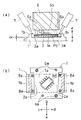
上記構成において、フォトダイオードPD付きプレート2の固定手順を説明すると、図6に仮想線で示すように、前記プレート2を位置決めアーム6の先端部下面に設けた永久磁石6b〔図1(a)参照〕に吸着させて該アーム6の先端部下面に突設した複数のピン6aに係止させ、前記位置決めアーム6を前後左右及び上下の3次元方向a〜fに移動させることにより、図1(a)に示すように、前記プレート2を筐体1の一端面1aから所定間隔αをおいて両突起部1b間に位置決めして、フォトダイオードPDの中心を対物レンズOLの軸心に一致させ、次に、図1(a)及び(b)に示すように、プレート2の両側縁2aの隅部と各突起部1bとの間の4箇所に注入器7により紫外線硬化性接着剤8aを少量注入し、その紫外線硬化性接着剤8aを紫外線の照射により硬化させてプレート2を筐体1に仮固定し、続いて、位置決めアーム6を上昇させてピン6aをプレート2から離間させ、図2(a)及び(b)に示すように、プレート2の両側縁2aの中央部と各突起部1bとの間の2箇所に熱硬化性接着剤8bを適量注入し、その熱硬化性接着剤8bを加熱により硬化させてプレート2を筐体1に本固定すればよい。
【0015】
上記構成によれば、熱硬化性接着剤8bによりフォトダイオードPD付きプレート2を筐体1に本固定する前に、位置決めアームにより前記プレート2を支持した状態で該プレート2を紫外線硬化性接着剤8aにより仮固定するようになっており、その仮固定後、前記プレート2から位置決めアームを直ちに離間させることができ、従来のように熱硬化性接着剤8bが硬化するまで位置決めアームによるプレート2の支持を維持する必要がないから、量産性に優れている。また、熱硬化性接着剤8bを注入する分だけ紫外線硬化性接着剤8aの注入量を少なくすることができるから、温度変化による伸縮率が大きいという紫外線硬化性接着剤8aの欠点を解消することができるものであって、前記両接着剤8a,8bの組み合わせによって、その両者8a,8bの欠点を解消し、フォトダイオードPD付きプレート2の筐体1への固定を迅速且つ正確に行なうことができる。
【0016】
更に、紫外線硬化性接着剤8aによりプレート2の四隅を筐体1に確実に仮固定することができると共に、硬化させた両紫外線硬化性接着剤8a間に熱硬化性接着剤8bが注入されるので、その熱硬化性接着剤8bの外部への流出を確実に阻止して、プレート2を筐体1に強固に本固定することができる。
【0017】
上記の実施の形態では、紫外線硬化性接着剤8aをプレート2の両側縁2aの隅部と各突起部1bとの間の4箇所に注入するようにしたが、これに限定されるわけではなく、例えば図3(a)に示すように、紫外線硬化性接着剤8aをプレート2の両側縁2aと各突起部1bとの間に所定間隔をおいて複数箇所(この例では6箇所)に注入して仮固定し、図3(b)に示すように、熱硬化性接着剤8bをプレート2の両側縁2aと各突起部1bとの間の紫外線硬化性接着剤8aを注入した箇所以外の空隙に注入して本固定するようにしてもよい。
【0018】
この構成によれば、紫外線硬化性接着剤8aによりプレート2の両側縁2aの複数箇所を筐体1に強固に仮固定しているので、本固定のために注入した熱硬化性接着剤8bが硬化するまでの間、そのプレート2を不測に動かないように確実に支持することができる。
【0019】
また、図4(a)に示すように、紫外線硬化性接着剤8aをプレート2の両側縁2aの中央部と各突起部1bとの間の2箇所に注入して仮固定し、図4(b)に示すように、熱硬化性接着剤8bをプレート2の両側縁2aの隅部と各突起部1bとの間の4箇所に注入して本固定するようにしてもよい。
【0020】
上記構成によれば、紫外線硬化性接着剤8aによりプレート2の両側縁2aの中央部だけを筐体1に仮固定するようになっており、その紫外線硬化性接着剤8aの注入量が極めて少ないから、温度変化による伸縮率が大きいという紫外線硬化性接着剤8aの特有の欠点を確実に解消することができる。
【0021】
【発明の効果】
本発明によれば、紫外線硬化性接着剤によりフォトダイオード(電子部品)付きプレートを筐体に仮固定するため、熱硬化性接着剤による本固定の際に前記プレートを支持する必要がなく、硬化に時間がかかるという熱硬化性接着剤の欠点を解消することができ、また、熱硬化性接着剤を注入する分だけ紫外線硬化性接着剤の注入量を少なくすることができるから、温度変化による伸縮率が大きいという紫外線硬化性接着剤の欠点を解消することができるものであって、前記両接着剤の組み合わせによって、その両者の欠点を解消し、フォトダイオード付きプレートの筐体への固定を迅速且つ正確に行なうことができる。
【0022】
更に、前記紫外線硬化性接着剤により前記プレートの四隅を筐体に確実に仮固定することができると共に、硬化させた両紫外線硬化性接着剤間に熱硬化性接着剤が注入されるので、その熱硬化性接着剤の外部への流出を確実に阻止して、プレートを筐体に強固に本固定することができる。
【図面の簡単な説明】
【図1】(a)は本発明の実施の一形態である光ピックアップにおけるフォトダイオード付きプレートの固定手順の前半を示す縦断面図、(b)は同一部切欠き平面図である。
【図2】(a)は同固定手順の後半を示す縦断面図、(b)は同一部切欠き平面図である。
【図3】(a)及び(b)は仮固定及び本固定の変形の一例を示す一部切欠き平面図である。
【図4】(a)及び(b)は仮固定及び本固定の変形の他の例を示す一部切欠き平面図である。
【図5】光ピックアップの作動原理を説明する概略縦断面図である。
【図6】同光ピックアップの要部を示す斜視図である。
【図7】(a)は従来例を示す縦断面図、(b)は同一部切欠き平面図である。
【符号の説明】
1 筐体
2 プレート
4 プレート
6 位置決めアーム
8 接着剤
8a 紫外線硬化性接着剤
8b 熱硬化性接着剤
PD フォトダイオード(電子部品)
LD 半導体レーザ(電子部品)[0001]
TECHNICAL FIELD OF THE INVENTION
The present invention relates to a method for fixing a plate provided with an electronic component including an optical pickup and a photodiode in a central portion, which is used for a display such as a DVD or a CD, and more particularly to a method for fixing the plate quickly and accurately. It was done.
[0002]
[Prior art]
2. Description of the Related Art Conventionally, there is a technique of an optical pickup described in Japanese Patent Application Laid-Open No. 62-89249, etc. An example thereof will be described with reference to FIG. 1b, the
[0003]
In the above configuration, the procedure for fixing the
[0004]
Conventionally, an ultraviolet-curable adhesive is generally used as the adhesive 8, and the ultraviolet-curable adhesive is applied to both
[0005]
[Problems to be solved by the invention]
In the above-mentioned conventional configuration, the
[0006]
Therefore, a thermosetting adhesive having a small expansion and contraction rate due to a temperature change is used as the adhesive 8, and the thermosetting adhesive is injected over the entire range between the
[0007]
The present invention has been made in view of the above-described conventional drawbacks, and provides an optical pickup and a method of fixing a plate with an electronic component, which can quickly and accurately fix a plate provided with electronic components such as a photodiode. The purpose is.
[0008]
[Means for Solving the Problems]
In order to achieve the above object, the invention according to
[0009]
According to the second aspect of the present invention, a pair of projections are integrally provided on one end surface of the housing at a predetermined interval, and the plate with the photodiode approaches the one end surface of the housing at a predetermined interval. The plate is positioned between the two projections, and the ultraviolet curable adhesive is injected into both corners and the center of each elongated gap between both side edges of the plate and each projection. The plate is temporarily fixed to the housing by curing the ultraviolet-curable adhesive by ultraviolet irradiation, and a thermosetting adhesive is provided in a gap between the ultraviolet-curable adhesive injection points in each of the elongated gaps. It is characterized in that an appropriate amount is injected, the thermosetting adhesive is cured by heating, and the plate is permanently fixed to the housing .
[0010]
According to a third aspect of the present invention, the plate is provided by locking a plate provided with a central part of an electronic component comprising a photodiode to a positioning arm, and moving the positioning arm in three-dimensional directions of front, rear, left, right, and up and down. To the one end surface of the housing at a predetermined interval, and position the plate between a pair of integrally projecting projections at one end surface of the housing at a predetermined opposing interval. A small amount of UV curable adhesive is injected into both corners or both corners and the center of each elongated gap between both side edges and each protrusion, and the UV curable adhesive is irradiated with ultraviolet light. To temporarily fix the plate to the housing, then separate the positioning arm from the plate, and apply an appropriate amount of the thermosetting adhesive to the gap between the ultraviolet curing adhesive injection points in each of the elongated gaps. Inject and It is characterized by cured by heating the thermosetting adhesive to the fixing plate to the housing.
[0011]
According to the above configuration, since the plate with the photodiode (electronic component) is temporarily fixed to the housing with the ultraviolet curable adhesive, there is no need to support the plate at the time of the permanent fixing with the thermosetting adhesive, and the curing is performed. The time-consuming process can eliminate the disadvantage of the thermosetting adhesive, and the amount of the UV-curable adhesive to be injected can be reduced by the amount of the injected thermosetting adhesive. It is possible to eliminate the drawback of the ultraviolet curable adhesive having a large expansion and contraction ratio, and to solve the both drawbacks by combining the two adhesives, thereby fixing the plate with the photodiode to the housing. It can be done quickly and accurately.
[0012]
Furthermore, since the four corners of the plate can be securely temporarily fixed to the housing by the ultraviolet-curable adhesive, and the thermosetting adhesive is injected between the two cured ultraviolet-curable adhesives. The outflow of the thermosetting adhesive to the outside can be reliably prevented, and the plate can be firmly permanently fixed to the housing.
[0013]
BEST MODE FOR CARRYING OUT THE INVENTION
FIGS. 1 and 2 show a fixed state of a
[0014]
In the above configuration, the procedure for fixing the
[0015]
According to the above configuration, before the
[0016]
Furthermore, the four corners of the
[0017]
In the above-described embodiment, the ultraviolet
[0018]
According to this configuration, a plurality of locations on both
[0019]
Further, as shown in FIG. 4 (a), an ultraviolet
[0020]
According to the above configuration, only the center of both
[0021]
【The invention's effect】
According to the present invention, since the plate with the photodiode (electronic component) is temporarily fixed to the housing with the ultraviolet curable adhesive, it is not necessary to support the plate at the time of the final fixing with the thermosetting adhesive, and the curing is performed. The time-consuming process can eliminate the disadvantage of the thermosetting adhesive, and the amount of the UV-curable adhesive to be injected can be reduced by the amount of the injected thermosetting adhesive. It is possible to eliminate the drawback of the ultraviolet curable adhesive having a large expansion and contraction ratio, and to solve the both drawbacks by combining the two adhesives, thereby fixing the plate with the photodiode to the housing. It can be done quickly and accurately.
[0022]
Furthermore, since the four corners of the plate can be securely temporarily fixed to the housing by the ultraviolet-curable adhesive, and the thermosetting adhesive is injected between the two cured ultraviolet-curable adhesives. The outflow of the thermosetting adhesive to the outside can be reliably prevented, and the plate can be firmly permanently fixed to the housing.
[Brief description of the drawings]
FIG. 1A is a longitudinal sectional view showing a first half of a procedure for fixing a plate with a photodiode in an optical pickup according to an embodiment of the present invention, and FIG. 1B is a cutaway plan view of the same part.
FIG. 2A is a longitudinal sectional view showing the latter half of the fixing procedure, and FIG. 2B is a cutaway plan view of the same part.
FIGS. 3A and 3B are partially cutaway plan views showing an example of a modification of temporary fixing and permanent fixing.
FIGS. 4A and 4B are partially cutaway plan views showing another example of a modification of the temporary fixing and the permanent fixing.
FIG. 5 is a schematic longitudinal sectional view for explaining the operation principle of the optical pickup.
FIG. 6 is a perspective view showing a main part of the optical pickup.
FIG. 7A is a longitudinal sectional view showing a conventional example, and FIG. 7B is a plan view with the same portion cut away.
[Explanation of symbols]
LD semiconductor laser (electronic parts)
Claims (3)
Priority Applications (2)
| Application Number | Priority Date | Filing Date | Title |
|---|---|---|---|
| JP2001144855A JP3552042B2 (en) | 2001-05-15 | 2001-05-15 | Fixing method of optical pickup and plate with electronic components |
| US10/135,688 US6741407B2 (en) | 2001-05-15 | 2002-05-01 | Optical pickup and method of fixing a plate with an electronic component |
Applications Claiming Priority (1)
| Application Number | Priority Date | Filing Date | Title |
|---|---|---|---|
| JP2001144855A JP3552042B2 (en) | 2001-05-15 | 2001-05-15 | Fixing method of optical pickup and plate with electronic components |
Publications (2)
| Publication Number | Publication Date |
|---|---|
| JP2002342947A JP2002342947A (en) | 2002-11-29 |
| JP3552042B2 true JP3552042B2 (en) | 2004-08-11 |
Family
ID=18990750
Family Applications (1)
| Application Number | Title | Priority Date | Filing Date |
|---|---|---|---|
| JP2001144855A Expired - Fee Related JP3552042B2 (en) | 2001-05-15 | 2001-05-15 | Fixing method of optical pickup and plate with electronic components |
Country Status (2)
| Country | Link |
|---|---|
| US (1) | US6741407B2 (en) |
| JP (1) | JP3552042B2 (en) |
Families Citing this family (7)
| Publication number | Priority date | Publication date | Assignee | Title |
|---|---|---|---|---|
| JP3552046B2 (en) * | 2001-09-13 | 2004-08-11 | 船井電機株式会社 | Mounting method of sensor in pickup head and pickup head |
| JP3775675B2 (en) | 2003-04-15 | 2006-05-17 | 船井電機株式会社 | Optical pickup |
| JP2005332552A (en) * | 2004-04-22 | 2005-12-02 | Sanyo Electric Co Ltd | Optical pickup device |
| JP4538416B2 (en) * | 2006-02-03 | 2010-09-08 | 株式会社日立メディアエレクトロニクス | Optical pickup device, manufacturing method thereof, and optical drive device |
| JP4804286B2 (en) * | 2006-09-11 | 2011-11-02 | 三洋電機株式会社 | Optical pickup device |
| JP2010282700A (en) * | 2009-06-05 | 2010-12-16 | Funai Electric Co Ltd | Optical pickup |
| EP2737498B1 (en) * | 2011-07-27 | 2017-03-29 | SRI International | Manufacturing using levitated manipulator robots |
Family Cites Families (3)
| Publication number | Priority date | Publication date | Assignee | Title |
|---|---|---|---|---|
| JPS57105472A (en) * | 1980-12-19 | 1982-06-30 | Matsushita Electric Ind Co Ltd | Adhesive for optical device |
| JPS6289249A (en) | 1985-10-16 | 1987-04-23 | Pioneer Electronic Corp | Structure of photodetector attached to plane part and its assembling method |
| US5350917A (en) * | 1991-12-27 | 1994-09-27 | Sony Corporation | Opto-magnetic recording polarization optical apparatus including a laser diode and a light absorbing film |
-
2001
- 2001-05-15 JP JP2001144855A patent/JP3552042B2/en not_active Expired - Fee Related
-
2002
- 2002-05-01 US US10/135,688 patent/US6741407B2/en not_active Expired - Fee Related
Also Published As
| Publication number | Publication date |
|---|---|
| US20020172145A1 (en) | 2002-11-21 |
| US6741407B2 (en) | 2004-05-25 |
| JP2002342947A (en) | 2002-11-29 |
Similar Documents
| Publication | Publication Date | Title |
|---|---|---|
| EP0473425B1 (en) | Optical disc apparatus for optically processing information | |
| JP3552042B2 (en) | Fixing method of optical pickup and plate with electronic components | |
| JP2010061771A (en) | Optical device | |
| JP2004029679A (en) | Optical module device, method of manufacturing the same, and projection tv system | |
| JP3663141B2 (en) | Optical head photo detector mounting device | |
| JP3584467B2 (en) | Optical pickup half mirror fixing device | |
| JP2005338679A (en) | Fixing method, and optical part and optical pickup device manufactured by using the same | |
| JP2002352445A (en) | Method for fixing plate equipped with optical pickup and electronic parts | |
| JP2007334951A (en) | Optical pickup and optical disk device | |
| JP2009146523A (en) | Light receiving unit and its manufacturing method, optical pickup device, and electronic apparatus | |
| US8448197B2 (en) | Optical pickup device with protrusions in a laser beam direction to shield ultraviolet light and method for manufacturing the same | |
| JP2002141363A (en) | Electronic component bonding apparatus | |
| JP4697173B2 (en) | Optical pickup | |
| JP4113052B2 (en) | Optical component mounting method and optical head manufacturing method using the same | |
| JP3546958B2 (en) | Optical pickup | |
| JP4177380B2 (en) | Optical pickup and method for bonding optical component to substrate in optical pickup | |
| JP2008084364A (en) | Optical pickup and assembling method thereof | |
| JP3087592U (en) | Optical pickup assembly equipment | |
| JP2006030752A (en) | Method for manufacturing diffraction element, optical head device and optical disk device | |
| JP3264068B2 (en) | Magneto-optical disk drive | |
| JP2000090481A (en) | Adhering device and adhering method for optical element | |
| JPH0441460Y2 (en) | ||
| JP2003151146A (en) | Optical pickup device | |
| JPH06203388A (en) | Device for fixing optical detector and optical head having the same | |
| JPH0935299A (en) | Objective lens supporting device for information accumulating device |
Legal Events
| Date | Code | Title | Description |
|---|---|---|---|
| TRDD | Decision of grant or rejection written | ||
| A01 | Written decision to grant a patent or to grant a registration (utility model) |
Free format text: JAPANESE INTERMEDIATE CODE: A01 Effective date: 20040407 |
|
| A61 | First payment of annual fees (during grant procedure) |
Free format text: JAPANESE INTERMEDIATE CODE: A61 Effective date: 20040420 |
|
| R150 | Certificate of patent or registration of utility model |
Free format text: JAPANESE INTERMEDIATE CODE: R150 |
|
| R250 | Receipt of annual fees |
Free format text: JAPANESE INTERMEDIATE CODE: R250 |
|
| FPAY | Renewal fee payment (event date is renewal date of database) |
Free format text: PAYMENT UNTIL: 20080514 Year of fee payment: 4 |
|
| FPAY | Renewal fee payment (event date is renewal date of database) |
Free format text: PAYMENT UNTIL: 20090514 Year of fee payment: 5 |
|
| FPAY | Renewal fee payment (event date is renewal date of database) |
Free format text: PAYMENT UNTIL: 20090514 Year of fee payment: 5 |
|
| FPAY | Renewal fee payment (event date is renewal date of database) |
Free format text: PAYMENT UNTIL: 20100514 Year of fee payment: 6 |
|
| FPAY | Renewal fee payment (event date is renewal date of database) |
Free format text: PAYMENT UNTIL: 20100514 Year of fee payment: 6 |
|
| FPAY | Renewal fee payment (event date is renewal date of database) |
Free format text: PAYMENT UNTIL: 20110514 Year of fee payment: 7 |
|
| LAPS | Cancellation because of no payment of annual fees |