【0001】
【産業上の利用分野】
この発明は、湖・沼・ダム等の深水層の循環曝気を大容量とすることを目的とした大容量深水曝気装置に関する。
【0002】
【従来の技術】
従来深水層と浅水層を別々に曝気する技術は知られていた(実公平4−22878号)。また複数本の揚水筒を束にして使用する大容量揚水装置も提案されていた(実公平4−41998号)。
【0003】
【発明により解決すべき課題】
前記従来の揚水装置は、国内各地に設置されて、多大の成果をあげている。
【0004】
また複数本の揚水筒を束にして使用することも行われているが、何れも浅水域又は上部水域において使用されており、深水層における使用例はない。
【0005】
然し乍ら比較的水深の大きい湖、沼において(例えば水深50m〜100m)、水深30m〜60m付近の深水域の曝気を目的とした場合に未だ有効な装置がない。例えば前記実公平4−22878号考案の場合には複数本の揚水筒を用いているが、上下関係はない。
【0006】
また実公平4−41998号の考案の場合には、上下揚水筒共に単筒である。従って大容量の循環揚水がむつかしい問題点があった。
【0007】
【課題を解決するための手段】
然るにこの発明は、下部揚水筒を複数本とし、しかも下部へ散気盤を設置して大容量の深水曝気を可能にし、前記従来の問題点を解決したのである。
【0008】
即ちこの発明は、複数本の間欠空気揚水筒の下部に整流筒の上部を連設し、該整流筒の下部外側に空気室を設けると共に、該空気室の外側に散気盤を配置し、かつ整流筒の内側にも気泡を送るべく散気管を配置して下部揚水装置とし、該下部揚水装置の上部に下部揚水装置の上昇水を案内する横方向案内板を設け、前記横方向案内板の上部に上部揚水筒を有する上部揚水装置を連設したことを特徴とする大容量深水曝気装置であり、複数本の間欠空気揚水筒の下部に整流筒の上部 を連設し、該整流筒の下部外側に空気室を設けると共に、散気盤を配置し、かつ整流筒の内側にも気泡を送るべく散気管を配置して下部揚水装置を構成し、この下部揚水装置の上部に上部揚水筒の空気室を連設し、該空気室に上部揚水筒の下部を連設すると共に、該上部揚水筒の外側へ所定の間隔を保って外筒を遊嵌することにより上部揚水装置を構成したことを特徴とする大容量深水曝気装置である。
【0009】
次に他の発明は、複数本の間欠空気揚水筒の下部を一本の整流筒の上部に連結し、該整流筒の下部側壁に環状の空気室と環状の散気管を設けて散気管の内側へ整流筒内と連通する多数の小孔を穿設し、該散気管に送気ホースを連結し、前記揚水筒を囲んで散気盤を配置したことを特徴とするものであり、上部揚水装置の空気室は、下部揚水装置で使用された空気の上昇路となる截頭円錐を設置し、前記使用された空気を捕集すべくなしたものである。
【0010】
前記発明において、上部揚水装置は、一本の揚水筒の外側へ所定の間隔をおいて外筒を遊嵌したけれども、上部揚水筒を複数本にしても同様である。また下部揚水筒の外側に所定間隔をいて外筒を設けることもできる。
【0011】
また散気盤は下部揚水筒の下部外側に設けるに際し、散気盤の空気を悉く揚水に混入して、溶存酸素量の増加を図ることもできる。
【0012】
【作用】
この発明によれば、少くとも下部揚水筒を複数本使用したので、単一揚水筒に期待できない大容量揚水を行い、これを循環させることができる。
【0013】
また下部揚水筒の下部に散気盤を設けたので、この散気盤により生成した気泡を微細にして、水深の大きい水域の曝気を自動的に行うことができる。
【0014】
【実施例1】
間欠空気の下部揚水筒1、1(4本1体にしてある)の下端に一本の整流筒2の上端を接続し、整流筒2の下部外側に空気室3を嵌装固着すると共に、環状の散気管4を設ける。前記空気室3の外側にも環状の散気盤5を設ける。
【0015】
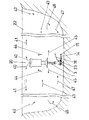
前記下部揚水筒1の上端部外側に補強帯6を固定し、該補強帯6と上部揚水筒8の下端に連設した截頭円錐7の内壁とを支杆9、9により支承させる。また上部揚水筒8の下部内側には、塞板10を設け、該塞板10の下面に有底筒11の上端を固定し、前記有底筒11と、塞板10の上部とを連通筒12で連通させたもので、図中13は有底筒11の上部側壁に穿設した連通孔、14、15、16は下部揚水筒の空気室及び散気管と散気盤の送気ホースである。
【0016】
前記上部揚水筒8の外側へ所定の間隔を保って外筒17を遊嵌し、数本の支持杆18、18により位置を固定する。図中19は上部揚水筒8の連通孔、20は浮室(浮子にすることもある)、21は下部揚水筒の揚水の案内板である。
【0017】
前記装置は図2のように、深水湖22などへ設置し、前記浮室20と、重錘23との間で本体を垂直に支持できる。
【0018】
前記実施例において、ホース16から、矢示24のように加圧空気を空気室3内へ送入し、内部の水位が、鎖線25に達すると、空気室内の空気は、矢示26、27、28のように一団となって、整流筒2内へ放出され、整流筒2内で気泡弾29を形成する。
【0019】
一方散気管4と散気盤5へも各送気ホース14、15から加圧空気が矢示30、31のように送入されるので、散気管4と、散気盤5から微小気泡32、33となって水中へ放出される。
【0020】
前記気泡弾20と微小気泡32、33とは、矢示34のように上昇して截頭円錐7に衝突し、空気は矢示35のように上昇し、連通孔13から有底筒11内に入り、その空気が連通筒12の下端まで達した際は一団となって連通筒12内を矢示36のように上昇し、気泡弾37となって矢示38のように上昇し、外筒17内へ放出される。従って外筒17内の水も矢示39のように吸い上げられ、図2中矢示40、40のように放散させられる。
【0021】
従って下部揚水は微小気泡を一部含んだまま矢示45、45のように横方向へ放散される。そこで下部揚水と、上部揚水とは図2中矢示40、41、42、43、44の循環と、矢示45、46、47の循環と上下2段で夫々対流を生じる。
【0022】
この場合に下部揚水筒1、1は十分の能力を発揮し、深水層の溶存酸素量を速かに改善させることができる。
【0023】
【実施例2】
この発明の他の実施例を図3に基づいて説明する。
【0024】
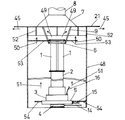
図3は実施例1において、下部揚水筒1、1の外側へ所定の間隔を保って外筒48を遊嵌したものである。
【0025】
下部揚水筒1、1に外筒48を遊嵌すると、下部揚水筒1、1の揚水が矢示49、49のように放散すると、下部揚水筒1、1の外壁と、外筒48の内壁との間の水を矢示50のように連行する。
【0026】
一方散気盤5の気泡も矢示51、51のように上昇するので、外筒48内には上昇流を生じ、それだけ大量の水が上昇して、矢示45、45のように拡散する。
【0027】
図中52、52は外筒48と截頭円錐7及び案内21との間の支杆であり、53、54は外筒48の上下の支持杆である。この実施例のようにすれば下部揚水筒による揚水量を更に大量にすることができる。
【0028】
【発明の効果】
この発明は、下部揚水筒を複数とし、その揚水量を改善できるので、公知の単筒の場合に比し、数倍の能力を発揮できる効果がある。
【0029】
また深水層は酸欠になり易いが、散気管及び散気盤によって微小気泡を生成し、酸素の溶解量の増加をはかったので溶存酸素量を改善できる効果がある。
【図面の簡単な説明】
【図1】この発明の一部を省畧した断面拡大図。
【図2】同じく設置状態の一部を省畧した図。
【図3】同じく下部揚水筒に外筒を遊嵌した実施例の一部断面図。
【符号の説明】
1 下部揚水筒
2 整流筒
3 空気室
4 散気管
5 散気盤
6 補強帯
7 截頭円錐
8 上部揚水筒
9 支杆
10 塞板
11 有底筒
12 連通筒
13、19 連通孔
14、15、16 送気ホース
17 外筒
18 支持杆
20 浮室
21 案内
22 深水湖
23 重錘
29、37 気泡弾
32、33 微小気泡
48 外筒[0001]
[Industrial applications]
The present invention relates to a large-capacity deep-water aeration apparatus for increasing the capacity of circulating aeration in deep-water layers such as lakes, swamps, and dams.
[0002]
[Prior art]
Conventionally, a technique for separately aerating a deep water layer and a shallow water layer has been known (Japanese Utility Model Publication No. 4-22878). A large-capacity water pump that uses a plurality of water pipes in a bundle has also been proposed (Japanese Utility Model Publication No. 4-41998).
[0003]
Problems to be solved by the invention
The conventional pumping devices have been installed in various parts of the country and have achieved great results.
[0004]
A plurality of pumping cylinders are also used as a bundle, but all of them are used in a shallow water area or an upper water area, and there is no use example in a deep water layer.
[0005]
However, in lakes and marshes having relatively large water depths (for example, water depths of 50 m to 100 m), there is still no effective device for the purpose of aerating deep water areas near water depths of 30 m to 60 m. For example, in the case of the invention of Japanese Utility Model Publication No. 4-22878, a plurality of pumping cylinders are used, but there is no vertical relation.
[0006]
In the case of the invention of Japanese Utility Model Publication No. 4-41998, both upper and lower pumping cylinders are single cylinders. Therefore, there is a problem that large-scale circulation pumping is difficult.
[0007]
[Means for Solving the Problems]
However, the present invention solves the above-mentioned conventional problems by providing a plurality of lower water pumping cylinders and installing a diffuser at the lower part to enable large-capacity deep-water aeration.
[0008]
That is, the present invention, the upper part of the straightening cylinder is continuously connected to the lower part of the plurality of intermittent air pumping cylinders, and an air chamber is provided outside the lower part of the straightening cylinder, and an air diffuser is arranged outside the air chamber , A diffuser pipe is also arranged inside the flow straightening tube to send air bubbles to form a lower pumping device, and a horizontal guide plate for guiding rising water of the lower pumping device is provided above the lower pumping device. A large-capacity deep-water aeration apparatus characterized by connecting an upper pumping device having an upper pumping cylinder at an upper portion of the rectifying cylinder, wherein an upper portion of a rectifying cylinder is continuously connected to a lower part of a plurality of intermittent air pumping cylinders, An air chamber is provided on the outside of the lower part , a diffuser plate is arranged , and a diffuser tube is also arranged inside the rectifying tube to send air bubbles. The air chamber of the water bottle is connected continuously, and the lower portion of the upper pumping cylinder is connected to the air chamber, A large capacity deep aerator, characterized in that to constitute a top pumping equipment by loosely fitting the outer cylinder with a predetermined gap to the outside of the upper pumping cylinder.
[0009]
Next, another invention connects the lower part of a plurality of intermittent air pumping cylinders to the upper part of one rectifying cylinder, and provides an annular air chamber and an annular diffusing pipe on the lower side wall of the rectifying cylinder to form an air diffusing pipe. bored a number of small holes communicating with the rectifying cylinder inwards, which connect the air hose to the diverging pipe, characterized in that a gas-Release diffuser surrounds the lifting water bottles, upper The air chamber of the pumping device is provided with a truncated cone serving as a rising path of the air used in the lower pumping device to collect the used air.
[0010]
In the above invention, the upper pumping device has the outer cylinder loosely fitted at a predetermined interval to the outside of one pumping cylinder, but the same applies to the case where a plurality of upper pumping cylinders are used. Further, outer cylinders may be provided at predetermined intervals outside the lower water pumping cylinder.
[0011]
In addition, when the diffuser is provided outside the lower part of the lower pumping cylinder, the air in the diffuser can be entirely mixed into the pump to increase the dissolved oxygen amount.
[0012]
[Action]
According to the present invention, since at least a plurality of lower pumping cylinders are used, large-capacity pumping that cannot be expected from a single pumping cylinder can be performed and circulated.
[0013]
In addition, since the air diffuser is provided at the lower part of the lower pumping cylinder, the air bubbles generated by the air diffuser can be made fine, and the aeration of a deep water area can be automatically performed.
[0014]
Embodiment 1
The upper end of one rectifying cylinder 2 is connected to the lower ends of the lower pumping cylinders 1 and 1 (made of four pieces) of the intermittent air, and the air chamber 3 is fitted and fixed to the outside of the lower part of the rectifying cylinder 2, An annular diffuser 4 is provided. An annular diffuser 5 is also provided outside the air chamber 3.
[0015]
A reinforcing band 6 is fixed to the outside of the upper end of the lower pumping cylinder 1, and the reinforcing band 6 and the inner wall of a truncated cone 7 connected to the lower end of the upper pumping cylinder 8 are supported by supporting rods 9, 9. Further, a closing plate 10 is provided inside the lower part of the upper pumping cylinder 8, the upper end of the bottomed cylinder 11 is fixed to the lower surface of the closing plate 10, and the bottomed cylinder 11 is connected to the upper part of the closing plate 10. In the figure, 13 is a communication hole drilled in the upper side wall of the bottomed cylinder 11, 14, 15, and 16 are air chambers of the lower pumping cylinder and air supply hoses of a diffuser pipe and a diffuser board. is there.
[0016]
The outer cylinder 17 is loosely fitted to the outside of the upper pumping cylinder 8 at a predetermined interval, and the position is fixed by several support rods 18. In the figure, 19 is a communication hole of the upper pumping cylinder 8, 20 is a floating chamber (may be a float), and 21 is a guide plate for pumping the lower pumping cylinder.
[0017]
The apparatus is installed in a deep water lake 22 or the like as shown in FIG. 2, and can vertically support the main body between the floating chamber 20 and the weight 23.
[0018]
In the above embodiment, pressurized air is fed into the air chamber 3 from the hose 16 as shown by arrow 24, and when the internal water level reaches the chain line 25, the air in the air chamber is changed to arrows 26 and 27. , 28, and are discharged into the rectifying cylinder 2 to form a bubble bullet 29 in the rectifying cylinder 2.
[0019]
On the other hand, pressurized air is also supplied from the air supply hoses 14 and 15 to the air diffuser 4 and the air diffuser 5 as indicated by arrows 30 and 31, so that the microbubbles 32 are transmitted from the air diffuser 4 and the air diffuser 5. , 33 and released into the water.
[0020]
The bubble bullet 20 and the microbubbles 32 and 33 rise as shown by an arrow 34 and collide with the truncated cone 7, and the air rises as shown by an arrow 35 and the air flows from the communication hole 13 into the bottomed cylinder 11. When the air reaches the lower end of the communication tube 12, it rises as a unit in the communication tube 12 as indicated by an arrow 36, and rises as a bubble bullet 37 as indicated by an arrow 38, and rises outside. Released into the cylinder 17. Therefore, the water in the outer cylinder 17 is also sucked up as indicated by an arrow 39 and diffused as indicated by arrows 40 and 40 in FIG.
[0021]
Accordingly, the lower pumping water is diffused in the lateral direction as indicated by arrows 45 and 45 while including some microbubbles. Therefore, the lower pumping and the upper pumping generate convection in two stages of upper and lower stages of circulation in arrows 40, 41, 42, 43 and 44 and circulation in arrows 45, 46 and 47 in FIG.
[0022]
In this case, the lower pumping cylinders 1 and 1 exhibit sufficient capacity, and the amount of dissolved oxygen in the deep water layer can be promptly improved.
[0023]
Embodiment 2
Another embodiment of the present invention will be described with reference to FIG.
[0024]
FIG. 3 shows the first embodiment in which the outer cylinder 48 is loosely fitted to the outside of the lower pumping cylinders 1 and 1 at a predetermined interval.
[0025]
When the outer cylinder 48 is loosely fitted to the lower pumping cylinders 1 and 1, the pumping of the lower pumping cylinders 1 and 1 disperses as indicated by arrows 49 and 49, and the outer walls of the lower pumping cylinders 1 and 1 and the inner wall of the outer cylinder 48. Is taken along as shown by arrow 50.
[0026]
On the other hand, the air bubbles in the diffuser 5 also rise as indicated by arrows 51 and 51, so that an ascending flow is generated in the outer cylinder 48, and a correspondingly large amount of water rises and diffuses as indicated by arrows 45 and 45. .
[0027]
In the figure, 52 and 52 are support rods between the outer cylinder 48 and the truncated cone 7 and the guide 21, and 53 and 54 are support rods above and below the outer cylinder 48. According to this embodiment, the amount of water pumped by the lower water pump can be further increased.
[0028]
【The invention's effect】
According to the present invention, a plurality of lower water pumping cylinders can be used to improve the amount of water pumping. Therefore, the present invention has the effect of exhibiting several times the capacity of a known single cylinder.
[0029]
In addition, although the deep water layer is easily deprived of oxygen, microbubbles are generated by a diffuser tube and a diffuser plate, and the amount of dissolved oxygen is increased, so that the dissolved oxygen amount can be improved.
[Brief description of the drawings]
FIG. 1 is an enlarged sectional view in which a part of the present invention is omitted.
FIG. 2 is a diagram in which a part of the installation state is omitted.
FIG. 3 is a partial cross-sectional view of an embodiment in which an outer cylinder is loosely fitted to a lower pumping cylinder.
[Explanation of symbols]
DESCRIPTION OF SYMBOLS 1 Lower pumping cylinder 2 Rectifier cylinder 3 Air chamber 4 Air diffuser 5 Diffusion board 6 Reinforcement band 7 Truncated cone 8 Upper pumping cylinder 9 Support rod 10 Closure plate 11 Bottom cylinder 12 Communication cylinders 13, 19 Communication holes 14, 15, Reference Signs List 16 air supply hose 17 outer cylinder 18 support rod 20 floating chamber 21 guide 22 deep water lake 23 weight 29, 37 bubble bullet 32, 33 micro bubble 48 outer cylinder