JP3551976B2 - Hybrid vehicle - Google Patents
Hybrid vehicle Download PDFInfo
- Publication number
- JP3551976B2 JP3551976B2 JP09624392A JP9624392A JP3551976B2 JP 3551976 B2 JP3551976 B2 JP 3551976B2 JP 09624392 A JP09624392 A JP 09624392A JP 9624392 A JP9624392 A JP 9624392A JP 3551976 B2 JP3551976 B2 JP 3551976B2
- Authority
- JP
- Japan
- Prior art keywords
- oil
- pressure
- motor
- transmission
- supplied
- Prior art date
- Legal status (The legal status is an assumption and is not a legal conclusion. Google has not performed a legal analysis and makes no representation as to the accuracy of the status listed.)
- Expired - Lifetime
Links
Images


Abstract
Description
【0001】
【産業上の利用分野】
本発明は、ハイブリッド型車両に関するものである。
【0002】
【従来の技術】
従来、車両は一般に、ガソリン機関であるエンジンを作動させることによって発生させた回転を自動変速機、マニュアル変速機等のトランスミッションを介して変速し、駆動輪に伝達するようにしている。前記ガソリン機関は、ガソリンと空気の混合気を圧縮状態で燃焼させ、この時発生するエネルギをエンジントルクに変換しているため、燃焼に伴う騒音が発生するだけでなく、排気ガスによって環境を汚染してしまう。
【0003】
一方、エンジンを電動機すなわちモータに置き換え、騒音や排気ガスの発生をなくした電気自動車が提供されている。この場合、車両にモータ及びバッテリを搭載し、前記モータによって駆動輪を回転させて走行するようにしている。したがって、車両の走行に伴う騒音はほとんど発生することがなく、しかも、排気ガスを発生することもない。
【0004】
ところが、電気自動車の場合、バッテリに充電することができる電気量には限度があり、航続距離が短くなってしまう。したがって、十分な航続距離を得るためには大きいバッテリを搭載する必要がある。また、通常の車両に搭載することができる程度の大きさのモータを使用した場合、エンジンによる場合と比較して発生するトルクの値が小さく、急発進、高負荷走行、高速走行等を行うことができない。
【0005】
そこで、エンジンとモータを併用したハイブリッド型車両が提供されている。この種のハイブリッド型車両は各種提供されていて、エンジンによって発電機を駆動して電気エネルギを発生させ、該電気エネルギによってモータを回転させ、その回転を駆動輪に伝達するシリーズ(直列)型のもの(特開昭62−104403号公報参照)や、エンジン及びモータによって直接駆動輪を回転させるパラレル(並列)型のものに分類される(特開昭59−63901号公報、米国特許明細書第4,533,011号参照)。
【0006】
【発明が解決しようとする課題】
しかしながら、前記従来のハイブリッド型車両においては、モータのコイルが過熱するのを防止するために、油をコイルに供給して冷却する必要があるが、コイルのほかトランスミッション部分についても潤滑し、冷却しようとすると次の問題が生じる。
【0007】
すなわち、トランスミッションのシャフト、ベアリング、ワンウェイクラッチ等の各部を潤滑し、冷却する場合には、大量の油を供給する必要はないが、所定以上の圧力でトランスミッション内に油を押し込むようにして供給する必要があるのに対して、モータを潤滑し、冷却する場合には、圧力を高くする必要はないが、冷却用として大量の油を供給する必要がある。
【0008】
ところが、トランスミッションの各部に供給する油の圧力を確保しようとしたときに、モータにおいて油の量を十分に確保することができないことがあり、コイルが焼け付いたり、モータの性能が低下してしまう。
また、モータに供給する油の量を確保しようとしたときに、トランスミッションに供給される油の圧力を十分に確保することができないことがあり、トランスミッションの各部を十分に潤滑し、冷却することができず、シャフト、ベアリング、ワンウェイクラッチ等にダメージを与える。
【0009】
本発明は、前記問題点を解決して、トランスミッションに対して十分な圧力で油を供給することができ、しかも、モータに対して十分な量の油を供給することができるハイブリッド型車両を提供することを目的とする。
【0010】
【課題を解決するための手段】
そのために、本発明のハイブリッド型車両においては、エンジン、該エンジンのトルクを伝達するトランスミッション(38)、及び車両を走行させるためのトルクを発生させるモータ(12)を備えるようになっている。
そして、前記モータ(12)のコイル(12c)に油を滴下又は噴射するために前記モータ(12)のケースに設けられたマニホルド(12d)と、油圧源(17)と、該油圧源(17)から供給された油を駆動用の圧力に調整する第2の調圧弁(18)、(19)と、該第2の調圧弁(18)、(19)からドレーンされた油を潤滑用の圧力に調整する第1の調圧弁(19)、(85)、(87)と、該第1の調圧弁(19)、(85)、(87)に接続され、前記潤滑用の圧力に調整された油を前記トランスミッション(38)に供給するための第1の油路(L−12)、(L−15a)、(L−15b)、(L−21)と、前記第1の調圧弁(19)、(85)、(87)に接続され、該第1の調圧弁(19)、(85)、(87)からドレーンされた油を前記マニホルド(12d)に供給する第2の油路(L−13)、(L−16)、(L−22)とを有する。
本発明の他のハイブリッド型車両においては、さらに、前記トランスミッション(38)はプラネタリギヤユニット(33)を備え、該プラネタリギヤユニット(33)に前記潤滑用の圧力に調整された油が供給される。
本発明の更に他のハイブリッド型車両においては、さらに、前記第1の油路(L−12)、(L−15a)、(L−15b)、(L−21)は、油の量を調整するオリフィス(86a)、(86b)を備える。
【0011】
本発明の更に他のハイブリッド型車両においては、エンジン、該エンジンのトルクを伝達するトランスミッション(38)、及び車両を走行させるためのトルクを発生させるモータ(12)を備えるようになっている。
そして、前記モータ(12)のコイル(12c)に油を滴下又は噴射するために前記モータ(12)のケースに設けられたマニホルド(12d)と、油圧源(17)と、該油圧源(17)から供給された油を駆動用の圧力に調整する調圧装置(19)と、該調圧装置(19)に接続され、調圧装置(19)からドレーンされた油を前記トランスミッション(38)の各部に供給するための第1の油路(L−6a)〜(L−16e)と、前記調圧装置(19)に接続され、該調圧装置(19)からドレーンされた油を前記マニホルド(12d)に供給するための第2の油路(L−7)とを有する。
また、前記第1の油路(L−6a)〜(L−16e)は、前記トランスミッション(38)に所定圧の油を供給するための第1のオリフィス(83a)〜(83e)を備える。そして、前記第2の油路(L−7)は、前記マニホルド(12d)に所定量の油を供給するための第2のオリフィス(84)を備える。
本発明の更に他のハイブリッド型車両においては、さらに、前記トランスミッション(38)はプラネタリギヤユニット(33)を備える。そして、該プラネタリギヤユニット(33)に前記調圧装置(19)からドレーンされた油が供給される。
本発明の更に他のハイブリッド型車両においては、さらに、前記駆動用の圧力はトルクコンバータ圧である。
本発明の更に他のハイブリッド型車両においては、さらに、前記駆動用の圧力は油圧サーボに供給される圧力である。
本発明の更に他のハイブリッド型車両においては、さらに、前記油圧源(17)はオイルポンプである。
【0012】
【作用及び発明の効果】
本発明によれば、前記のようにハイブリッド型車両においては、エンジン、該エンジンのトルクを伝達するトランスミッション、及び車両を走行させるためのトルクを発生させるモータを備えるようになっている。
そして、前記モータのコイルに油を滴下又は噴射するために前記モータのケースに設けられたマニホルドと、油圧源と、該油圧源から供給された油を駆動用の圧力に調整する第2の調圧弁と、該第2の調圧弁からドレーンされた油を潤滑用の圧力に調整する第1の調圧弁と、該第1の調圧弁に接続され、前記潤滑用の圧力に調整された油を前記トランスミッションに供給するための第1の油路と、前記第1の調圧弁に接続され、該第1の調圧弁からドレーンされた油を前記マニホルドに供給する第2の油路とを有する。
【0013】
この場合、油圧源から供給された油は、第2の調圧弁によって駆動用の圧力に調整され、第2の調圧弁からドレーンされた油は、第1の調圧弁によって潤滑用の圧力に調整され、潤滑用の圧力に調整された油は、第1の油路を介してトランスミッションに供給され、第1の調圧弁からドレーンされた油は、第2の油路を介してマニホルドに供給される。
したがって、潤滑用の圧力に調整された油を、例えば、トランスミッションの各部に供給すると、十分な圧力の油をトランスミッションの各部に供給することができる。その結果、トランスミッションの各部を十分に潤滑し、冷却することができるので、トランスミッションの各部が焼き付いたり、破損したりするのを防止することができる。
また、第1の調圧弁からドレーンされた油を前記マニホルドに供給するようになっているので、十分な量の油をマニホルドに供給し、コイルを冷却することができる。その結果、コイルが焼き付いたり、モータの性能が低下したりするのを防止することができる。
【0014】
本発明の他のハイブリッド型車両においては、エンジン、該エンジンのトルクを伝達するトランスミッション、及び車両を走行させるためのトルクを発生させるモータを備えるようになっている。
そして、前記モータのコイルに油を滴下又は噴射するために前記モータのケースに設けられたマニホルドと、油圧源と、該油圧源から供給された油を駆動用の圧力に調整する調圧装置と、該調圧装置に接続され、調圧装置からドレーンされた油を前記トランスミッションの各部に供給するための第1の油路と、前記調圧装置に接続され、該調圧装置からドレーンされた油を前記マニホルドに供給するための第2の油路とを有する。
また、前記第1の油路は、前記トランスミッションに所定圧の油を供給するための第1のオリフィスを備える。そして、前記第2の油路は、前記マニホルドに所定量の油を供給するための第2のオリフィスを備える。
この場合、油圧源から供給された油は、調圧装置によって駆動用の圧力に調整され、調圧装置からドレーンされた油は、第1の油路を介してトランスミッションの各部に、第2の油路を介してマニホルドに、それぞれ供給される。
【0015】
【実施例】
以下、本発明の実施例について図面を参照しながら詳細に説明する。
FF(フロントエンジン・フロントドライブ)式の車両には、回転軸が横方向になるようにエンジンを搭載した横置FF車両と、回転軸が縦方向になるようにエンジンを搭載した縦置FF車両とがある。
【0016】
前記横置FF車両には、エンジンの回転をカウンタドライブギヤとカウンタドリブンギヤから成るカウンタギヤを介してディファレンシャル装置に伝達するカウンタギヤ式のものと、エンジンの回転をチェーンを介してディファレンシャル装置に伝達するチェーン式のものがあり、前記カウンタギヤ式のものは、更にカウンタギヤを中間部に設けた中間部配置型のものと、カウンタギヤを後部に設けた後部配置型のものがある。
【0017】
本実施例の場合、回転軸が横方向になるようにエンジンを搭載した横置FF車両であり、エンジンの回転をカウンタギヤを介してディファレンシャル装置に伝達するカウンタギヤ式であり、かつ、カウンタギヤを中間部に設けた中間部配置型の車両について説明するが、他の車両に適用することもできる。
図2は本発明の第1の実施例を示すハイブリッド型車両の概略図である。
【0018】
図2において、12は制御装置によって選択的に駆動されるモータ、14はディファレンシャル装置、31は流体伝動装置としてのトルクコンバータ、C1はエンジン11が発生したトルクによって車両を走行させる場合に係合する第1クラッチ、33はプラネタリギヤユニットである。該プラネタリギヤユニット33はシンプルプラネタリ型のものであり、リングギヤR、ピニオンギヤP、サンギヤS及び前記ピニオンギヤPを支持するキャリヤCRから成る。また、B1は前記サンギヤSを選択的に係合する第1ブレーキ、F1は第1ワンウェイクラッチである。前記プラネタリギヤユニット33、第1ブレーキB1及び第1ワンウェイクラッチF1によってトランスミッション38が構成される。
【0019】
また、41は駆動装置ケースであり、該駆動装置ケース41内に前記モータ12、ディファレンシャル装置14、トルクコンバータ31、第1クラッチC1及びトランスミッション38が収容される。42は前記ディファレンシャル装置14によって減速され、差動させられた回転を左右の駆動輪に伝達するための駆動軸である。45はエンジン11の出力軸、46はトルクコンバータ31の出力軸、47はプラネタリギヤユニット33の入力軸、48は伝動軸である。
【0020】
前記モータ12は、駆動装置ケース41に固定されたステータ12a及び伝動軸48に連結されたロータ12bから成っている。前記ステータ12aにはコイル12cが巻装されていて、該コイル12cに駆動電流を流すことによってロータ12bを回転させることができる。
そして、前記エンジン11又はモータ12の回転は、前記伝動軸48に固定されたカウンタドライブギヤ52に伝達される。
【0021】
前記伝動軸48と平行にカウンタドライブシャフト53が配設されていて、該カウンタドライブシャフト53にカウンタドリブンギヤ54が設けられる。該カウンタドリブンギヤ54は前記カウンタドライブギヤ52と噛合しており、該カウンタドライブギヤ52の回転を出力ギヤ55に伝達する。
そして、該出力ギヤ55の回転は、出力ギヤ55と噛合する出力大歯車56に伝達される。出力ギヤ55の歯数に対して前記出力大歯車56の歯数は多く、前記出力ギヤ55及び出力大歯車56で最終減速機を構成する。該最終減速機によって減速された前記出力大歯車56の回転は、ディファレンシャル装置14に伝達され、差動させられて左右の駆動軸42に伝達される。
【0022】
前記構成のハイブリッド型車両においては、二つのモードで車両を走行させることができる。すなわち、前記モータ12に駆動電流を供給せず、エンジン11を作動させると、エンジン11の回転は出力軸45を介してトルクコンバータ31に伝達され、さらに出力軸46を介して第1クラッチC1に伝達される。そして、該第1クラッチC1が係合されると出力軸46に伝達された回転は、入力軸47を介してプラネタリギヤユニット33のキャリヤCRに伝達される。
【0023】
前記プラネタリギヤユニット33においては、第1ブレーキB1が解放されると、キャリヤCRに入力された回転によって第1ワンウェイクラッチF1がロックされて直結状態になる。したがって、入力軸47の回転がそのまま伝動軸48に伝達される。また、第1ブレーキB1が係合されるとサンギヤSが固定され、リングギヤRから増速された回転が出力され、伝動軸48を介してカウンタドライブギヤ52に伝達される。
【0024】
そして、前述したようにカウンタドライブギヤ52に伝達された回転は、カウンタドリブンギヤ54を介してカウンタドライブシャフト53に伝達され、出力ギヤ55及び出力大歯車56で構成される最終減速機によって減速されてディファレンシャル装置14に伝達される。この時、エンジン11のみによって車両を走行させることができる。
【0025】
次に、前記エンジン11を停止させるか、第1クラッチC1を解放してモータ12を駆動すると、該モータ12がトルクを発生する。該トルクは伝動軸48に出力され、同様にカウンタドライブギヤ52に伝達される。この時、モータ12のみによって車両を走行させることができる。
また、前記エンジン11を作動させ、第1クラッチC1を係合してモータ12を駆動すると、エンジン11及びモータ12によって車両を走行させることができる。
【0026】
さらに、前記エンジン11を作動させ、第1クラッチC1を係合することによって、モータ12において回生電流を発生させるようにすることもできる。
このように、第1クラッチC1を解放し、モータ12を駆動するとモータ12が発生したトルクを使用し、第1クラッチC1を係合しモータ12を停止させると、エンジン11が発生したトルクを使用して車両を走行させることができる。
【0027】
そして、市街地走行において排気ガスの発生をなくすか減少させるため、また、航続距離を確保するために、低速及び中速で走行する場合にはモータ12を、高速で走行する場合にはエンジン11を駆動するようにしている。ただし、モータ12の駆動中においても、補機を駆動するためエンジン11にアイドル運転をさせておくことも可能である。なお、18はプライマリレギュレータバルブ、19はセカンダリレギュレータバルブ、62は第2シフトバルブ、63はソレノイドバルブ、64は制御装置(ECU)である。
【0028】
前記構成のハイブリッド型車両において、トランスミッション38はプラネタリギヤユニット33を有しており、サンギヤSがベアリングを介して入力軸47に回転自在に支持され、ピニオンギヤPがサンギヤS及びリングギヤRと噛合するようになっている。また、前記サンギヤSとキャリヤCR間には第1ワンウェイクラッチF1が配設されている。さらに、サンギヤSと駆動装置ケース41間には、交互に配列された薄板から成る第1ブレーキB1が配設され、摩擦によって係合させられる。
【0029】
このように、前記トランスミッション38においては、各部が相対的に摺動して作動するようになっていて、摺動時に摩擦熱が発生するため、プラネタリギヤユニット33の摺動部分、第1ブレーキB1の摺動部分に油を供給して潤滑するとともに冷却する。
また、前記モータ12が発生したトルクによって車両を走行させるに当たり、比較的低速で高負荷になる場合には、大電流がコイル12cに供給され、コイル12cの発熱量が大きくなってしまう。したがって、前記モータ12の上方の駆動装置ケース41内から油を供給し、該油によってモータ12を冷却するようにしている。
【0030】
次に、トランスミッション38及びモータ12の潤滑・冷却系について説明する。
図1は本発明の第1の実施例を示すハイブリッド型車両におけるトランスミッション及びモータの潤滑・冷却系を示す図である。
図において、17はエンジン11(図2)が発生したトルクによって回転させられる油圧源としてのオイルポンプ、81は該オイルポンプ17に吸引される油をろ過するためのストレーナ、18はプライマリレギュレータバルブ(他の調圧弁)である。前記オイルポンプ17から吐出された油は、油路L−1を介してプライマリレギュレータバルブ18に送られ、該プライマリレギュレータバルブ18においてライン圧(設定圧)に調整される。調圧された油は、油路L−2を介して図示しないマニュアルバルブに送られ、第1シフトバルブ69、第2シフトバルブ62等を介して油圧サーボB−1、C−1に供給される。
【0031】
前記プライマリレギュレータバルブ18において、調圧が行われた後のドレーンされた油は、油路L−3を介してセカンダリレギュレータバルブ19(調圧弁)に供給される。そして、該セカンダリレギュレータバルブ19で調圧された油は、油路L−4を介してトルクコンバータ圧(設定圧)としてトルクコンバータ31に供給される。
そして、セカンダリレギュレータバルブ19で調圧が行われた後のドレーンされた油が、油路L−5及び油路L−6a〜L−6eを介してトランスミッション38の各部、例えば、プラネタリギヤユニット33のサンギヤSと入力軸47との間のベアリングが配設される部分、ピニオンギヤPとサンギヤS及びリングギヤRとが噛合する部分、ピニオンギヤPがピニオンシャフトに支持される部分、第1ワンウェイクラッチF1のアウタレースとインナレースとの間、第1ブレーキB1の各薄板間等に潤滑用及び冷却用として供給される。なお、プライマリレギュレータバルブ18及びセカンダリレギュレータバルブ19によって調圧装置が構成される。
【0032】
また、前記セカンダリレギュレータバルブ19で調圧が行われた後のドレーンされた油は、油路L−7(第2の油路)を介してモータ12にも供給される。すなわち、前記油路L−7は、モータ12の上方の駆動装置ケース41内に設けられたマニホルド12dに連通しており、該マニホルド12dを介してモータ12のコイル12cに油が滴下又は噴射され、モータ12を冷却する。
【0033】
ところで、トランスミッション38の各部を潤滑し、冷却する場合には、大量の油を供給する必要はないが、流動抵抗に抗するため所定以上の圧力でトランスミッション38内に油を押し込むようにして供給する必要があるのに対して、前記モータ12を潤滑し、冷却する場合には、圧力を高くする必要はないが、冷却用として大量の油を供給する必要がある。
【0034】
そこで、前記トランスミッション38に油を供給する油路L−6a〜L−6e、及びモータ12に油を供給する油路L−7に油圧・油量調整装置を設けるようにしている。すなわち、本実施例においては、前記油路L−6a〜L−6eを介してトランスミッション38の各部に供給される油の圧力を設定圧に調整するため、また、油路L−7を介してモータ12に供給される油の量を設定量に調整するため、油路L−6a〜L−6eのそれぞれにオリフィス83a〜83eが、油路L−7にオリフィス84が設けられる。
【0035】
そして、前記オリフィス83a〜83eは、トランスミッション38の各部に対して設定圧で油を噴出させることができるだけの径を、前記オリフィス84はモータ12に対して設定量の油を供給することができるだけの径を有するようにしている。
したがって、トランスミッション38の各部に供給する油の圧力を確保しようとしたときに、モータ12において油の量を十分に確保することができ、コイル12cが焼け付いたり、モータ12の性能が低下してしまうことはない。
【0036】
また、モータ12に供給する油の量を確保しようとしたときに、トランスミッション38に供給される油の圧力を十分に確保することができ、トランスミッション38の各部を十分に潤滑し、冷却することができるため、入力軸47、ベアリング、第1ワンウェイクラッチF1等が焼け付いたり、破損したりすることがない。
【0037】
次に、本発明の第2の実施例について説明する。
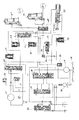
図3は本発明の第2の実施例を示すハイブリッド型車両における要部油圧回路図である。
図において、16はオイルパン、17はエンジン11(図2)の回転によって駆動され、前記オイルパン16の油を吸引して吐出するオイルポンプ、18はプライマリレギュレータバルブ、19はセカンダリレギュレータバルブであり、該セカンダリレギュレータバルブ19で調圧された油はトルクコンバータ31の冷却回路20に供給され、セカンダリレギュレータバルブ19で調圧が行われた後のドレーンされた油がトランスミッション38のギヤトレインにおけるシャフト、ベアリング、ワンウェイクラッチ等の油滑用及び冷却用として使用される。前記トルクコンバータ31の冷却回路20は、クーラバイパスバルブ21、チェックバルブ22及び図示しないオイルクーラから成る。
【0038】
25はプレッシャリリーフバルブ、26はトルクコンバータコントロールバルブであり、ロックアップソレノイドバルブ27のオン・オフによって切り換わり、トルクコンバータ31のロックアップ装置を係脱する。
また、C−1は第1クラッチC1の油圧サーボ、62は該油圧サーボC−1に対して油を給排する第2シフトバルブ、63は該第2シフトバルブ62を切り換えるソレノイドバルブ、67は前記油圧サーボC−1に連通するように配設されるアキュムレータである。前記ソレノイドバルブ63は、制御装置64によってオン・オフされ、前記第2シフトバルブ62を切り換え、モータによる走行とエンジンによる走行を切り換える。
【0039】
また、65は前記トルクコンバータ31のロックアップ装置を係脱するためのトルクコンバータコントロールバルブであり、該トルクコンバータコントロールバルブ65を介してトルクコンバータ31に油が供給される。
B−1はモータ12が発生したトルクによって走行している時に係脱させられる第1ブレーキB1の油圧サーボ、69は低速走行と中速走行を切り換える第1シフトバルブ、70は該第1シフトバルブ69を切り換えるソレノイドバルブ、71は前記油圧サーボB−1に連通するように配設されるアキュムレータである。
【0040】
そして、72はマニュアルバルブ、73はソレノイドモジュレータバルブ、74はストレーナ、75は前記プライマリレギュレータバルブ18の信号圧を発生するラインプレッシャコントロールバルブ、85は前記セカンダリレギュレータバルブ19で調圧が行われた後のドレーンされた油を、トランスミッション38の潤滑用及び冷却用として調圧するモジュレータバルブである。
【0041】
前記構成のハイブリッド型車両においては、低速及び中速で走行する場合にトルクコンバータ31を使用しないようにしている。そのため、オイルポンプ17とトルクコンバータコントロールバルブ65間に前記第2シフトバルブ62が配設されている。そして、該第2シフトバルブ62を、オイルポンプ17と油圧サーボC−1が連通するように切り換えると、オイルポンプ17とトルクコンバータコントロールバルブ65が連通するようになっている。
【0042】
したがって、前記第1クラッチC1を係合して、エンジン11が発生したトルクによって車両を走行させる場合のみ、トルクコンバータ31に油が供給され、第1クラッチC1を解放してモータ12が発生したトルクによって車両を走行させる場合には、トルクコンバータ31には油を供給しないので油の量を節約することができる。
【0043】
図4は本発明の第2の実施例を示すハイブリッド型車両におけるトランスミッション及びモータの潤滑・冷却系を示す図である。
図において、17はオイルポンプ、81はストレーナ、18はプライマリレギュレータバルブ(第3の調圧弁)である。前記オイルポンプ17から吐出された油は、油路L−1を介してプライマリレギュレータバルブ18に送られ、該プライマリレギュレータバルブ18においてライン圧(第3の設定圧)に調整される。調圧された油は油路L−2を介してマニュアルバルブ72(図3)に送られ、第1シフトバルブ69、第2シフトバルブ62等を介して油圧サーボB−1又は油圧サーボC−1に供給される。
【0044】
前記プライマリレギュレータバルブ18において調圧が行われた後のドレーンされた油は、油路L−3を介してセカンダリレギュレータバルブ19(第2の調圧弁)に供給される。そして、該セカンダリレギュレータバルブ19で調圧された油は、油路L−4を介してトルクコンバータ圧(第2の設定圧)としてトルクコンバータ31に供給される。
そして、セカンダリレギュレータバルブ19で調圧が行われた後のドレーンされた油が、油路L−11を介してモジュレータバルブ85(第1の調圧弁)に供給され、該モジュレータバルブ85においてトランスミッション38(図2)の潤滑用及び冷却用としてトランスミッション圧(第1の設定圧)に調圧される。調圧された油は、油路L−12(第1の油路)を介してトランスミッション38の各部に潤滑用及び冷却用として供給される。
【0045】
また、前記モジュレータバルブ85で調圧が行われた後のドレーンされた油は、油路L−13(第2の油路)を介してモータ12に供給される。そのため、前記油路L−13は、モータ12の上方の駆動装置ケース41内に設けられたマニホルド12dに連通しており、該マニホルド12dを介してモータ12のコイル12cに油が滴下又は噴射され、モータ12を冷却する。
【0046】
前記モジュレータバルブ85は、前記油路L−12を介してトランスミッション38の各部に供給される油の圧力を設定圧に調整するとともに、油路L−13を介してモータ12に供給される油の量を確保するように設定されている。
次に、本発明の第3の実施例について説明する。
図5は本発明の第3の実施例を示すハイブリッド型車両におけるトランスミッション及びモータの潤滑・冷却系を示す図である。
【0047】
図において、17はオイルポンプ、81はストレーナ、18はプライマリレギュレータバルブである。前記オイルポンプ17から吐出された油は、油路L−1を介してプライマリレギュレータバルブ18に送られ、該プライマリレギュレータバルブ18においてライン圧に調整される。調圧された油は油路L−2を介してマニュアルバルブ72(図3)に送られ、第1シフトバルブ69、第2シフトバルブ62等を介して油圧サーボB−1や油圧サーボC−1に供給される。
【0048】
前記プライマリレギュレータバルブ18において調圧が行われた後のドレーンされた油は、油路L−3を介してセカンダリレギュレータバルブ19(第1の調圧弁)に供給される。そして、該セカンダリレギュレータバルブ19で調圧された油は、油路L−15aを介してトルクコンバータ圧(第2の設定圧)としてトルクコンバータ31に供給されるとともに、油路L−15bを介してトランスミッション38(図2)の各部に潤滑用及び冷却用として供給される。
【0049】
前記トルクコンバータ31に供給する油の圧力とトランスミッション38の各部に供給する油の圧力、すなわち、トランスミッション圧(第1の設定圧)を調整するために、前記油路L−15a,L−15bにそれぞれオリフィス86a,86bが配設される。
そして、セカンダリレギュレータバルブ19で調圧が行われた後のドレーンされた油が、油路L−16を介してモータ12に供給される。そのため、前記油路L−16は、モータ12の上方の駆動装置ケース41内に配設されたマニホルド12dに連通しており、該マニホルド12dを介してモータ12のコイル12cに油が滴下又は噴射され、モータ12を冷却する。
【0050】
前記セカンダリレギュレータバルブ19は、前記油路L−15aを介してトランスミッション38の各部に供給される油の圧力を設定圧に調整するとともに、油路L−16を介してモータ12に供給される油の量を確保するように設定されている。
図6は本発明の第4の実施例を示すハイブリッド型車両におけるトランスミッション及びモータの潤滑・冷却系を示す図である。
【0051】
図において、17はオイルポンプ、81はストレーナ、18はプライマリレギュレータバルブである。前記オイルポンプ17から吐出された油は、油路L−1を介してプライマリレギュレータバルブ18(第3の調圧弁)に送られ、該プライマリレギュレータバルブ18においてライン圧(第3の設定圧)に調整される。調圧された油は油路L−2を介してマニュアルバルブ72(図3)に送られ、第1シフトバルブ69、第2シフトバルブ62等を介して油圧サーボB−1又は油圧サーボC−1に供給される。
【0052】
前記プライマリレギュレータバルブ18において調圧が行われた後のドレーンされた油は、油路L−3を介してセカンダリレギュレータバルブ19(第2の調圧弁)に供給される。そして、該セカンダリレギュレータバルブ19で調圧された油は、油路L−4を介してトルクコンバータ圧(第2の設定圧)としてトルクコンバータ31に供給される。
そして、セカンダリレギュレータバルブ19で調圧が行われた後のドレーンされた油が、油路L−20を介してリリーフバルブ87(第1の調圧弁)に送られ、該リリーフバルブ87によって設定された圧力(第1の設定圧)の油が、油路L−21を介してトランスミッション38(図2)の各部に潤滑用及び冷却用として供給される。
【0053】
また、油路L−21内の油の圧力が設定圧以上であると、前記リリーフバルブ87は解放されるが、この時ドレーンされた油が油路L−22(第2の油路)を介してモータ12に供給される。そのため、前記油路L−22は、モータ12の上方の駆動装置ケース41内に設けられたマニホルド12dに連通しており、該マニホルド12dを介してモータ12のコイル12cに油が滴下又は噴射され、モータ12を冷却する。
【0054】
前記リリーフバルブ87は、前記油路L−21を介してトランスミッション38の各部に供給される油の圧力を設定圧に調整するとともに、油路L−22を介してモータ12に供給される油の量を確保するように設定されている。
【図面の簡単な説明】
【図1】本発明の第1の実施例を示すハイブリッド型車両におけるトランスミッション及びモータの潤滑・冷却系を示す図である。
【図2】本発明の第1の実施例を示すハイブリッド型車両の概略図である。
【図3】本発明の第1の実施例を示すハイブリッド型車両における要部油圧回路図である。
【図4】本発明の第2の実施例を示すハイブリッド型車両におけるトランスミッション及びモータの潤滑・冷却系を示す図である。
【図5】本発明の第3の実施例を示すハイブリッド型車両におけるトランスミッション及びモータの潤滑・冷却系を示す図である。
【図6】本発明の第4の実施例を示すハイブリッド型車両におけるトランスミッション及びモータの潤滑・冷却系を示す図である。
【符号の説明】
11 エンジン
12 モータ
17 オイルポンプ
18 プライマリレギュレータバルブ
19 セカンダリレギュレータバルブ
31 トルクコンバータ
38 トランスミッション
83a〜83e,84,86a,86b オリフィス
L−6a〜L−6e,L−12,L−15b,L−21 油路(第1の油路)L−7,L−13,L−16,L−22 油路(第2の油路)[0001]
[Industrial applications]
The present invention relates to a hybrid vehicle.
[0002]
[Prior art]
2. Description of the Related Art Conventionally, a vehicle generally changes the speed of rotation generated by operating an engine, which is a gasoline engine, through a transmission such as an automatic transmission or a manual transmission and transmits the rotation to driving wheels. The gasoline engine burns a mixture of gasoline and air in a compressed state, and converts the energy generated at that time into engine torque, not only generating noise due to combustion, but also polluting the environment with exhaust gas. Resulting in.
[0003]
On the other hand, electric vehicles have been provided in which the engine is replaced by an electric motor, thereby eliminating the generation of noise and exhaust gas. In this case, a motor and a battery are mounted on the vehicle, and the vehicle runs by rotating drive wheels by the motor. Therefore, almost no noise is generated due to running of the vehicle, and no exhaust gas is generated.
[0004]
However, in the case of an electric vehicle, the amount of electricity that can be charged to the battery is limited, and the cruising distance is reduced. Therefore, it is necessary to mount a large battery to obtain a sufficient cruising distance. In addition, when a motor having a size large enough to be mounted on a normal vehicle is used, the value of the generated torque is smaller than that of the case of using an engine, and sudden start, high load running, high speed running, etc. Can not.
[0005]
Therefore, a hybrid vehicle using both an engine and a motor has been provided. Various types of hybrid vehicles of this type are provided, and a series (series) type in which a generator is driven by an engine to generate electric energy, a motor is rotated by the electric energy, and the rotation is transmitted to driving wheels. (See JP-A-62-104403) and a parallel type in which the drive wheels are directly rotated by an engine and a motor (JP-A-59-63901; U.S. Pat. 4,533,011).
[0006]
[Problems to be solved by the invention]
However, in the above-mentioned conventional hybrid vehicle, it is necessary to supply oil to the coil to cool it in order to prevent the motor coil from overheating, but lubricate and cool the transmission as well as the coil. Then, the following problem occurs.
[0007]
In other words, when lubricating and cooling each part of the transmission shaft, bearings, one-way clutch, etc., it is not necessary to supply a large amount of oil, but the oil is supplied by pushing the oil into the transmission at a predetermined pressure or more On the other hand, when lubricating and cooling the motor, it is not necessary to increase the pressure, but it is necessary to supply a large amount of oil for cooling.
[0008]
However, when trying to secure the pressure of the oil supplied to each part of the transmission, the motor may not be able to secure a sufficient amount of oil, and the coil may burn or the performance of the motor may deteriorate. .
Also, when trying to secure the amount of oil to be supplied to the motor, the pressure of the oil to be supplied to the transmission may not be able to be sufficiently ensured.Therefore, it is possible to sufficiently lubricate and cool each part of the transmission. Inability to do so damages shafts, bearings, one-way clutches, etc.
[0009]
The present invention solves the above problems and provides a hybrid vehicle that can supply oil at a sufficient pressure to a transmission and can supply a sufficient amount of oil to a motor. The purpose is to do.
[0010]
[Means for Solving the Problems]
For this purpose, the hybrid vehicle of the present invention includes an engine, a transmission (38) for transmitting the torque of the engine, and a motor (12) for generating a torque for running the vehicle.
Then, a manifold (12d) provided in a case of the motor (12) for dropping or injecting oil to the coil (12c) of the motor (12), a hydraulic source (17), and the hydraulic source (17) ), The second pressure regulating valves (18), (19) for adjusting the oil supplied from the second pressure regulating valves (18), (19) to lubricating oil drained from the second pressure regulating valves (18), (19). First pressure regulating valves (19), (85), (87) for adjusting pressure and connected to the first pressure regulating valves (19), (85), (87) to regulate to the lubricating pressure. First oil passages (L-12), (L-15a), (L-15b), (L-21) for supplying the supplied oil to the transmission (38), and the first pressure regulating valve (19), (85), (87), and the first pressure regulating valve (19), (85), (87) Second oil passage for supplying the drain oils in the manifold (12d) (L-13), (L-16), and a (L-22).
In another hybrid vehicle of the present invention, the transmission (38) further includes a planetary gear unit (33), and the oil adjusted to the lubricating pressure is supplied to the planetary gear unit (33).
In still another hybrid vehicle according to the present invention, the first oil passages (L-12), (L-15a), (L-15b), and (L-21) further adjust the amount of oil. Orifices (86a) and (86b).
[0011]
Still another hybrid vehicle according to the present invention includes an engine, a transmission (38) for transmitting torque of the engine, and a motor (12) for generating torque for running the vehicle.
Then, a manifold (12d) provided in a case of the motor (12) for dropping or injecting oil to the coil (12c) of the motor (12), a hydraulic source (17), and the hydraulic source (17) ), And a pressure regulator (19) for adjusting the oil supplied from the pressure regulator (19) to the pressure for driving, and the oil (38) connected to the pressure regulator (19) and drained from the pressure regulator (19). The first oil passages (L-6a) to (L-16e) for supplying to the respective parts of the above and the pressure adjusting device (19), and the oil drained from the pressure adjusting device (19) A second oil passage (L-7) for supplying to the manifold (12d).
The first oil passages (L-6a) to (L-16e) include first orifices (83a) to (83e) for supplying oil of a predetermined pressure to the transmission (38). The second oil passage (L-7) includes a second orifice (84) for supplying a predetermined amount of oil to the manifold (12d).
In still another hybrid vehicle according to the present invention, the transmission (38) further includes a planetary gear unit (33). Then, the drained oil is supplied from the pressure adjusting device (19) to the planetary gear unit (33).
In still another hybrid vehicle according to the present invention, the driving pressure is a torque converter pressure.
In still another hybrid vehicle according to the present invention, the driving pressure is a pressure supplied to a hydraulic servo.
In still another hybrid vehicle according to the present invention, the hydraulic power source (17) is an oil pump.
[0012]
[Action and effect of the invention]
According to the present invention, as described above, the hybrid vehicle includes the engine, the transmission that transmits the torque of the engine, and the motor that generates the torque for running the vehicle.
A manifold provided in the case of the motor for dropping or injecting oil to the coil of the motor; a hydraulic source; and a second controller for adjusting the oil supplied from the hydraulic source to a driving pressure. A pressure valve, a first pressure regulating valve that regulates oil drained from the second pressure regulating valve to a lubricating pressure, and an oil connected to the first pressure regulating valve and regulated to the lubricating pressure. A first oil passage for supplying the transmission; and a second oil passage connected to the first pressure regulating valve for supplying oil drained from the first pressure regulating valve to the manifold.
[0013]
In this case, the oil supplied from the hydraulic pressure source is adjusted to the driving pressure by the second pressure regulating valve, and the oil drained from the second pressure regulating valve is regulated to the lubricating pressure by the first pressure regulating valve. The oil adjusted to the lubricating pressure is supplied to the transmission via the first oil passage, and the oil drained from the first pressure regulating valve is supplied to the manifold via the second oil passage. You.
Therefore, when the oil adjusted to the lubricating pressure is supplied to, for example, each part of the transmission, it is possible to supply oil having a sufficient pressure to each part of the transmission. As a result, each part of the transmission can be sufficiently lubricated and cooled, so that each part of the transmission can be prevented from being seized or damaged.
Further, since oil drained from the first pressure regulating valve is supplied to the manifold, a sufficient amount of oil can be supplied to the manifold, and the coil can be cooled. As a result, it is possible to prevent the coil from burning or the performance of the motor from deteriorating.
[0014]
Another hybrid vehicle of the present invention includes an engine, a transmission for transmitting torque of the engine, and a motor for generating torque for running the vehicle.
And, a manifold provided in the case of the motor for dripping or injecting oil into the coil of the motor, a hydraulic pressure source, and a pressure regulator for adjusting the oil supplied from the hydraulic pressure source to a driving pressure. A first oil passage connected to the pressure regulating device for supplying oil drained from the pressure regulating device to each section of the transmission; and a first oil passage connected to the pressure regulating device and drained from the pressure regulating device. A second oil passage for supplying oil to the manifold.
Further, the first oil passage includes a first orifice for supplying oil of a predetermined pressure to the transmission. The second oil passage includes a second orifice for supplying a predetermined amount of oil to the manifold.
In this case, the oil supplied from the hydraulic pressure source is adjusted to the driving pressure by the pressure adjusting device, and the oil drained from the pressure adjusting device is transmitted to the second portion of the transmission via the first oil passage to the second portion of the transmission. Each is supplied to the manifold via an oil passage.
[0015]
【Example】
Hereinafter, embodiments of the present invention will be described in detail with reference to the drawings.
FF (Front Engine / Front Drive) type vehicles include horizontal FF vehicles equipped with an engine so that the rotation axis is horizontal, and vertical FF vehicles equipped with an engine so that the rotation axis is vertical. There is.
[0016]
The laterally mounted FF vehicle has a counter gear type in which the rotation of the engine is transmitted to a differential device through a counter gear including a counter drive gear and a counter driven gear, and a rotation transmission of the engine is transmitted to a differential device through a chain. There is a chain type, and the counter gear type includes an intermediate portion type in which a counter gear is provided in an intermediate portion, and a rear portion type in which a counter gear is provided in a rear portion.
[0017]
In the case of the present embodiment, the vehicle is a laterally mounted FF vehicle equipped with an engine such that the rotation axis is in the horizontal direction, and is a counter gear type that transmits the rotation of the engine to a differential device via a counter gear. Will be described in the intermediate portion arrangement type vehicle provided in the intermediate portion, but the present invention can be applied to other vehicles.
FIG. 2 is a schematic diagram of a hybrid vehicle showing a first embodiment of the present invention.
[0018]
In FIG. 2, 12 is a motor selectively driven by the control device, 14 is a differential device, 31 is a torque converter as a fluid transmission device, and C1 is engaged when the vehicle is driven by the torque generated by the engine 11. The first clutch 33 is a planetary gear unit. The
[0019]
Reference numeral 41 denotes a drive device case, in which the motor 12, the
[0020]
The motor 12 includes a stator 12 a fixed to a drive device case 41 and a
The rotation of the engine 11 or the motor 12 is transmitted to a
[0021]
A counter drive shaft 53 is provided in parallel with the
The rotation of the
[0022]
In the hybrid vehicle having the above configuration, the vehicle can be driven in two modes. That is, when the engine 11 is operated without supplying a drive current to the motor 12, the rotation of the engine 11 is transmitted to the
[0023]
In the
[0024]
Then, as described above, the rotation transmitted to the
[0025]
Next, when the engine 11 is stopped or the first clutch C1 is released to drive the motor 12, the motor 12 generates torque. The torque is output to the
When the engine 11 is operated and the first clutch C1 is engaged to drive the motor 12, the vehicle can be driven by the engine 11 and the motor 12.
[0026]
Further, it is also possible to generate a regenerative current in the motor 12 by operating the engine 11 and engaging the first clutch C1.
As described above, when the first clutch C1 is released and the motor 12 is driven, the torque generated by the motor 12 is used. When the first clutch C1 is engaged and the motor 12 is stopped, the torque generated by the engine 11 is used. To run the vehicle.
[0027]
Then, in order to eliminate or reduce the generation of exhaust gas in city driving, and to secure a cruising distance, the motor 12 is used when driving at low speed and medium speed, and the engine 11 is used when driving at high speed. I try to drive. However, even while the motor 12 is being driven, it is possible to cause the engine 11 to idle in order to drive the accessories.
[0028]
In the hybrid vehicle having the above configuration, the
[0029]
As described above, in the
Also, when the vehicle is driven by the torque generated by the motor 12 and the load is relatively low and the load is relatively high, a large current is supplied to the coil 12c, and the heat generated by the coil 12c increases. Therefore, oil is supplied from inside the drive device case 41 above the motor 12, and the motor 12 is cooled by the oil.
[0030]
Next, the lubrication / cooling system of the
FIG. 1 is a diagram showing a lubrication / cooling system of a transmission and a motor in a hybrid vehicle according to a first embodiment of the present invention.
In the figure,
[0031]
In the
Then, the drained oil after the pressure is adjusted by the
[0032]
Further, the drained oil after the pressure is adjusted by the
[0033]
By the way, when lubricating and cooling each part of the
[0034]
Therefore, an oil pressure / oil amount adjusting device is provided in the oil passages L-6a to L-6e for supplying oil to the
[0035]
The orifices 83a to 83e have a diameter enough to allow oil to be jetted to each part of the
Therefore, when trying to ensure the pressure of the oil supplied to each part of the
[0036]
Further, when trying to secure the amount of oil to be supplied to the motor 12, the pressure of the oil supplied to the
[0037]
Next, a second embodiment of the present invention will be described.
FIG. 3 is a main part hydraulic circuit diagram of a hybrid vehicle showing a second embodiment of the present invention.
In the figure, 16 is an oil pan, 17 is an oil pump driven by the rotation of the engine 11 (FIG. 2) to suck and discharge oil from the
[0038]
C-1 is a hydraulic servo of the first clutch C1, 62 is a second shift valve that supplies and discharges oil to and from the hydraulic servo C-1, 63 is a solenoid valve that switches the
[0039]
B-1 is a hydraulic servo of the first brake B1 which is disengaged when traveling by the torque generated by the
[0040]
72 is a manual valve, 73 is a solenoid modulator valve, 74 is a strainer, 75 is a line pressure control valve that generates a signal pressure of the
[0041]
In the hybrid vehicle having the above configuration, the
[0042]
Therefore, only when the first clutch C1 is engaged and the vehicle is driven by the torque generated by the engine 11, the oil is supplied to the
[0043]
FIG. 4 is a view showing a lubrication / cooling system of a transmission and a motor in a hybrid vehicle according to a second embodiment of the present invention.
In the figure, 17 is an oil pump, 81 is a strainer, and 18 is a primary regulator valve (third pressure regulating valve). The oil discharged from the
[0044]
The drained oil after the pressure adjustment in the
Then, the drained oil after the pressure has been adjusted by the
[0045]
The drained oil after the pressure adjustment by the
[0046]
The
Next, a third embodiment of the present invention will be described.
FIG. 5 is a view showing a lubrication / cooling system of a transmission and a motor in a hybrid vehicle according to a third embodiment of the present invention.
[0047]
In the figure, 17 is an oil pump, 81 is a strainer, and 18 is a primary regulator valve. The oil discharged from the
[0048]
The drained oil after pressure adjustment in the
[0049]
In order to adjust the pressure of the oil supplied to the
Then, the drained oil after the pressure has been adjusted by the
[0050]
The
FIG. 6 is a view showing a lubrication / cooling system of a transmission and a motor in a hybrid vehicle according to a fourth embodiment of the present invention.
[0051]
In the figure, 17 is an oil pump, 81 is a strainer, and 18 is a primary regulator valve. The oil discharged from the
[0052]
The drained oil after the pressure adjustment in the
Then, the drained oil after the pressure has been adjusted by the
[0053]
When the pressure of the oil in the oil passage L-21 is equal to or higher than the set pressure, the
[0054]
The
[Brief description of the drawings]
FIG. 1 is a diagram showing a lubrication / cooling system of a transmission and a motor in a hybrid vehicle according to a first embodiment of the present invention.
FIG. 2 is a schematic view of a hybrid vehicle showing a first embodiment of the present invention.
FIG. 3 is a main part hydraulic circuit diagram of the hybrid vehicle according to the first embodiment of the present invention.
FIG. 4 is a diagram showing a lubrication / cooling system of a transmission and a motor in a hybrid vehicle according to a second embodiment of the present invention.
FIG. 5 is a view showing a lubrication / cooling system of a transmission and a motor in a hybrid vehicle according to a third embodiment of the present invention.
FIG. 6 is a view showing a lubrication / cooling system of a transmission and a motor in a hybrid vehicle according to a fourth embodiment of the present invention.
[Explanation of symbols]
11 Engine
12 motor
17 Oil pump
18 Primary regulator valve
19 Secondary regulator valve
31 Torque converter
38 Transmission
83a-83e, 84, 86a, 86b Orifice
L-6a to L-6e, L-12, L-15b, L-21 Oil passages (first oil passages) L-7, L-13, L-16, L-22 Oil passages (second oil passage) Road)
Claims (8)
前記モータのコイルに油を滴下又は噴射するために前記モータのケースに設けられたマニホルドと、
油圧源と、
該油圧源から供給された油を駆動用の圧力に調整する第2の調圧弁と、
該第2の調圧弁からドレーンされた油を潤滑用の圧力に調整する第1の調圧弁と、
該第1の調圧弁に接続され、前記潤滑用の圧力に調整された油を前記トランスミッションに供給するための第1の油路と、
前記第1の調圧弁に接続され、該第1の調圧弁からドレーンされた油を前記マニホルドに供給する第2の油路とを有することを特徴とするハイブリッド型車両。 An engine, a transmission that transmits torque of the engine, and a hybrid vehicle including a motor that generates torque for running the vehicle,
A manifold provided in the case of the motor to drip or inject oil into the coil of the motor,
A hydraulic source,
A second pressure regulating valve for adjusting the oil supplied from the hydraulic pressure source to a driving pressure;
A first pressure regulating valve for adjusting the oil drained from the second pressure regulating valve to a lubricating pressure;
A first oil passage connected to the first pressure regulating valve for supplying oil adjusted to the lubricating pressure to the transmission ;
Connected to said first pressure regulating valve, a hybrid vehicle, wherein the benzalkonium the drain oils from said first pressure regulating valve having a second oil path for supplying to said manifold.
該プラネタリギヤユニットに前記潤滑用の圧力に調整された油が供給される請求項1に記載のハイブリッド型車両。 The transmission includes a planetary gear unit,
Hybrid vehicle according to claim 1 in which the oil that has been adjusted to the pressure for the lubricant to the planetary gear unit Ru is supplied.
前記モータのコイルに油を滴下又は噴射するために前記モータのケースに設けられたマニホルドと、
油圧源と、
該油圧源から供給された油を駆動用の圧力に調整する調圧装置と、
該調圧装置に接続され、調圧装置からドレーンされた油を前記トランスミッションの各部に供給するための第1の油路と、
前記調圧装置に接続され、該調圧装置からドレーンされた油を前記マニホルドに供給するための第2の油路とを有するとともに、
前記第1の油路は、前記トランスミッションに所定圧の油を供給するための第1のオリフィスを備え、前記第2の油路は、前記マニホルドに所定量の油を供給するための第2のオリフィスを備えることを特徴とするハイブリッド型車両。An engine, a transmission that transmits torque of the engine, and a hybrid vehicle including a motor that generates torque for running the vehicle,
A manifold provided in the case of the motor to drip or inject oil into the coil of the motor ,
A hydraulic source,
A pressure regulator for adjusting the oil supplied from the hydraulic source to a driving pressure;
A first oil passage connected to the pressure regulating device for supplying oil drained from the pressure regulating device to each portion of the transmission;
A second oil passage connected to the pressure regulating device and configured to supply oil drained from the pressure regulating device to the manifold ;
The first oil passage includes a first orifice for supplying oil at a predetermined pressure before Symbol transmission, the second oil passage, a second for supplying a predetermined amount of oil to the manifold A hybrid vehicle comprising an orifice as described above.
該プラネタリギヤユニットに前記調圧装置からドレーンされた油が供給される請求項4に記載のハイブリッド型車両。 The transmission includes a planetary gear unit,
The hybrid vehicle according to claim 4, wherein oil drained from the pressure adjusting device is supplied to the planetary gear unit .
Priority Applications (1)
| Application Number | Priority Date | Filing Date | Title |
|---|---|---|---|
| JP09624392A JP3551976B2 (en) | 1992-04-16 | 1992-04-16 | Hybrid vehicle |
Applications Claiming Priority (1)
| Application Number | Priority Date | Filing Date | Title |
|---|---|---|---|
| JP09624392A JP3551976B2 (en) | 1992-04-16 | 1992-04-16 | Hybrid vehicle |
Publications (2)
| Publication Number | Publication Date |
|---|---|
| JPH05286368A JPH05286368A (en) | 1993-11-02 |
| JP3551976B2 true JP3551976B2 (en) | 2004-08-11 |
Family
ID=14159794
Family Applications (1)
| Application Number | Title | Priority Date | Filing Date |
|---|---|---|---|
| JP09624392A Expired - Lifetime JP3551976B2 (en) | 1992-04-16 | 1992-04-16 | Hybrid vehicle |
Country Status (1)
| Country | Link |
|---|---|
| JP (1) | JP3551976B2 (en) |
Cited By (1)
| Publication number | Priority date | Publication date | Assignee | Title |
|---|---|---|---|---|
| CN111042891A (en) * | 2019-12-31 | 2020-04-21 | 宁波吉利罗佑发动机零部件有限公司 | Extended-range lubrication management system, lubrication management method and vehicle |
Families Citing this family (3)
| Publication number | Priority date | Publication date | Assignee | Title |
|---|---|---|---|---|
| US6622804B2 (en) | 2001-01-19 | 2003-09-23 | Transportation Techniques, Llc. | Hybrid electric vehicle and method of selectively operating the hybrid electric vehicle |
| JP4069950B2 (en) * | 2006-09-20 | 2008-04-02 | トヨタ自動車株式会社 | Vehicle drive device and vehicle |
| JP5149974B2 (en) * | 2011-02-17 | 2013-02-20 | アイシン・エィ・ダブリュ株式会社 | Vehicle drive device |
-
1992
- 1992-04-16 JP JP09624392A patent/JP3551976B2/en not_active Expired - Lifetime
Cited By (2)
| Publication number | Priority date | Publication date | Assignee | Title |
|---|---|---|---|---|
| CN111042891A (en) * | 2019-12-31 | 2020-04-21 | 宁波吉利罗佑发动机零部件有限公司 | Extended-range lubrication management system, lubrication management method and vehicle |
| CN111042891B (en) * | 2019-12-31 | 2021-08-03 | 宁波吉利罗佑发动机零部件有限公司 | Extended-range lubrication management system, lubrication management method and vehicle |
Also Published As
| Publication number | Publication date |
|---|---|
| JPH05286368A (en) | 1993-11-02 |
Similar Documents
| Publication | Publication Date | Title |
|---|---|---|
| US9528436B2 (en) | Hybrid drive device | |
| JP3835007B2 (en) | Working fluid supply device for automatic transmission | |
| US5415603A (en) | Hydraulic control system for hybrid vehicle | |
| US8187147B2 (en) | Hydraulic control system for multi-mode hybrid transmission and method of regulating the same | |
| US8857188B2 (en) | Hybrid drive device | |
| US8784249B2 (en) | Automatic transmission for hybrid vehicle | |
| US8057355B2 (en) | Hydraulic control system for multi-mode hybrid transmission and method of regulating the same | |
| JP3182960B2 (en) | Hydraulic control device for hybrid vehicle | |
| JP3182987B2 (en) | Lubrication system for hybrid vehicles | |
| CN107178611B (en) | Vehicle console device | |
| JPH09109705A (en) | Hybrid driver | |
| WO2006089376A1 (en) | Drive system with fluid pump | |
| JP2004100827A (en) | Hydraulic control unit of vehicle | |
| JP2014126081A (en) | Vehicular transmission device | |
| CN110431332B (en) | Oil supply device | |
| JP4258904B2 (en) | Control device for vehicle oil pump | |
| JPH0654409A (en) | Hybrid type vehicle | |
| JP3551976B2 (en) | Hybrid vehicle | |
| JP4106864B2 (en) | Vehicle control device | |
| JP5115465B2 (en) | Drive device | |
| JP2003130189A (en) | Lubricating device | |
| JP4743992B2 (en) | Vehicle control device | |
| JPH0638303A (en) | Hybrid vehicle | |
| JP2005180620A (en) | Lubricating/cooling device for continuously variable transmission for vehicle | |
| US11415028B2 (en) | Hybrid vehicle |
Legal Events
| Date | Code | Title | Description |
|---|---|---|---|
| A521 | Written amendment |
Free format text: JAPANESE INTERMEDIATE CODE: A523 Effective date: 20040318 |
|
| A61 | First payment of annual fees (during grant procedure) |
Free format text: JAPANESE INTERMEDIATE CODE: A61 Effective date: 20040420 |
|
| R150 | Certificate of patent or registration of utility model |
Free format text: JAPANESE INTERMEDIATE CODE: R150 |
|
| R250 | Receipt of annual fees |
Free format text: JAPANESE INTERMEDIATE CODE: R250 |
|
| FPAY | Renewal fee payment (event date is renewal date of database) |
Free format text: PAYMENT UNTIL: 20090514 Year of fee payment: 5 |
|
| FPAY | Renewal fee payment (event date is renewal date of database) |
Free format text: PAYMENT UNTIL: 20090514 Year of fee payment: 5 |
|
| FPAY | Renewal fee payment (event date is renewal date of database) |
Free format text: PAYMENT UNTIL: 20100514 Year of fee payment: 6 |
|
| FPAY | Renewal fee payment (event date is renewal date of database) |
Free format text: PAYMENT UNTIL: 20110514 Year of fee payment: 7 |
|
| FPAY | Renewal fee payment (event date is renewal date of database) |
Free format text: PAYMENT UNTIL: 20110514 Year of fee payment: 7 |
|
| FPAY | Renewal fee payment (event date is renewal date of database) |
Free format text: PAYMENT UNTIL: 20120514 Year of fee payment: 8 |
|
| EXPY | Cancellation because of completion of term |