JP3550339B2 - Externally heated rotary kiln - Google Patents
Externally heated rotary kiln Download PDFInfo
- Publication number
- JP3550339B2 JP3550339B2 JP2000098869A JP2000098869A JP3550339B2 JP 3550339 B2 JP3550339 B2 JP 3550339B2 JP 2000098869 A JP2000098869 A JP 2000098869A JP 2000098869 A JP2000098869 A JP 2000098869A JP 3550339 B2 JP3550339 B2 JP 3550339B2
- Authority
- JP
- Japan
- Prior art keywords
- tube
- rotary kiln
- packing
- furnace tube
- furnace
- Prior art date
- Legal status (The legal status is an assumption and is not a legal conclusion. Google has not performed a legal analysis and makes no representation as to the accuracy of the status listed.)
- Expired - Lifetime
Links
Images


Description
【0001】
【発明の属する技術分野】
この発明は、セラミックス製の炉心管を用いた外熱式ロータリキルンに関するものである。
【0002】
【従来の技術】
高純度が要求されるセラミック原料等の焼成や乾燥に使用される外熱式ロータリキルンでは、炉心管材料によるコンタミネーションを防止するために、セラミックス製の炉心管が使用されている。セラミックス製炉心管は、優れた耐熱性を有するが、熱応力等によるクラックが生じやすい問題がある。このため、セラミックス製炉心管の支持方法や保護方法に色々な工夫が試みられている。
【0003】
例えば、特開平10−148469号公報に開示された外熱式ロータリキルンでは、図6に示すように、セラミックス製炉心管51の支持部52を軸方向4ヶ所に設けて支持スパンを短くし、これらの支持部52の間に加熱手段としての伝熱ヒータ53を配置している。各支持部52は周方向に4分割されており、分割された各支持部52には、炉心管51の締め付け力の調整と芯出し調整を行うために、半径方向に進退可能な支持棒(図示省略)が取り付けられている。支持棒と炉心管51との間隙には、セラミックファイバ等のブランケット状の詰め物54が充填されており、炉心管51は熱膨張時に各支持部52で軸方向に移動して、軸方向の熱応力が解除されるとしている。
【0004】
また、特開平6−3054号公報に開示されたものでは、図7に示すように、セラミックス製炉心管55を耐熱金属製の外筒56の中に挿入し、両者の隙間にセラミックファイバブランケット等の不定形断熱材(図示省略)を詰め込み、炉心管55を保護するようにしている。加熱手段としてのヒータ57は、外筒56を取り囲んで炉体58の中に配設されている。このものでは、熱応力等により炉心管55に多少のクラックが生じても、炉心管55が外筒56で保護されているので、さほどの不都合を生じることなく運転を継続できるとしている。
【0005】
前者は、炉心管51の支持部52で炉心管51の軸方向の移動を容認しているので、炉心管51の軸方向の熱応力は緩和することができるが、炉心管51の芯出しを行うために、各支持部52での半径方向の締め付け力を確保する必要があるので、支持部52における炉心管51円周方向の熱膨張が拘束され、熱膨張が拘束されない支持部52以外の部分との間に大きな熱ひずみ差を生じ、これらの境界部分で発生する周方向の熱応力でクラックを生じやすい問題がある。
【0006】
後者は、炉心管55を全長に渡って詰め物を介して外筒56で支持しているので、軸方向にも周方向にも局所的に大きな熱ひずみ差は生じず、熱応力によるクラックを防止できる効果は有するが、炉心管55と外筒56との間に断熱材が詰め込まれているので、熱効率が悪くなる問題がある。
【0007】
【発明が解決しようとする課題】
そこで、この発明の課題は、セラミックス製炉心管にクラックが発生せず、かつ、高い熱効率を確保できる外熱式ロータリキルンを提供することである。
【0008】
【課題を解決するための手段】
上記の課題を解決するために、この発明は、炉心管がセラミックスで一体に形成された外熱式ロータリキルンにおいて、炉心管の少なくとも両端部を、回転自在に支持された金属製の保護管で覆い、この保護管が炉心管の両端部を覆う各部位の保護管内面側にパッキンボックスを形成し、このパッキンボックスに炉心管の外周面全周に当接するグランドパッキンを収納して、パッキンボックスの押さえ板とパッキン押さえによりグランドパッキンの両端を挟持し、このグランドパッキンにより炉心管を軸方向に摺動可能に支持した構成を採用した。
【0009】
すなわち、炉心管の少なくとも両端部を金属製の保護管で覆い、この保護管が炉心管の両端部を覆う部位で、回転部の軸封部材として使用されるグランドパッキンを活用して炉心管をソフトに支持し、この支持部で炉心管を締め付けることなく、かつ、炉心管の軸方向への摺動も可能とし、炉心管の軸方向および円周方向いずれにおいても、大きな熱応力や熱応力勾配が発生しないようにした。
【0010】
前記炉心管の軸方向への移動を規制する手段を設けることにより、万が一の炉心管の抜け止めをすることができる。
【0011】
前記グランドパッキンによる炉心管の支持位置を、前記保護管の支持位置に合致させて設けることにより、グランドパッキンの炉心管への当たりをより均一にすることができる。
【0012】
【発明の実施の形態】
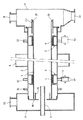
以下、図1乃至図5に基づき、この発明の実施形態を説明する。図1乃至図4は、第1の実施形態を示す。この外熱式ロータリキルンは、図1および図2に示すように、セラミックス製炉心管1が金属製の保護管2に内嵌され、保護管2の両端部内面側にパッキンボックス3が形成され、各パッキンボックス3にグランドパッキン4が収納されて、炉心管1がグランドパッキン4を介して保護管2に支持されている。両端部を支持された炉心管1の中央部は、保護管2とともに加熱手段としての電気炉5の中に通されている。なお、加熱手段としては、熱風炉等を採用することもできる。
【0013】
前記炉心管1の供給端側には入口フード6が、排出端側には出口フード7が設けられ、原料の供給管8が入口フード6を貫通して、炉心管1の供給端に挿入されている。出口フード7の上部には空気の入口9が、入口フード6の上部には排ガスの出口10が設けられ、出口フード7の下部に製品の排出口11が設けられている。なお、供給管8は振動手段(図示省略)により振動を付与され、原料をスムーズに供給できるようになっている。
【0014】
前記保護管2の外周面には、パッキンボックス3の軸方向位置と合致させて2つのタイヤ12、13が取り付けられ、これらのタイヤ12、13を介して、保護管2が各一対のローラ14、15の上に回転自在に支持されている。また、入口フード6と供給端側のタイヤ12の間の外周面にはスプロケット16が取り付けられており、スプロケット16に巻き掛けられるチェーンにより保護管2が回転され、これとともにグランドパッキン4を介して保護管2に支持された炉心管1も回転されるようになっている。
【0015】
図3に示すように、前記供給端側のタイヤ12を支持するローラ14には、タイヤ12の両端を挟む鍔17が設けられており、保護管2はローラ14による支持点を中心として左右に熱膨張し、熱膨張による軸方向変位は排出端側で大きくなる。このため、排出端側のタイヤ13を支持するローラ15は、この軸方向変位に対応できるように、幅広に形成されている。
【0016】
前記保護管2の供給端側には、炉心管1の軸方向移動を規制する環状のストッパ18が取り付けられ、ストッパ18に、炉心管1の供給端側内周に突き出す円筒部19が設けられている。この円筒部19は、炉心管1端面とストッパ18との隙間から原料が落下するのを防止する。
【0017】
一方、保護管2の排出端側には、炉心管1の排出端側を覆って炉心管1の外側に延長された筒状の排出ガイド20が取り付けられている。この排出ガイド20は、炉心管1が熱膨張により伸縮しても、製品を出口フード7の所定の位置に安定して落下させるためのものである。また、排出ガイド20の端部内側面には、炉心管1の軸方向移動を規制する4つのストッパ21が、90°の位相で突出するように設けられている。
【0018】
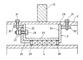
図4に示すように、前記パッキンボックス3は、一端に外向きのフランジ22を有する筒部材23と環状の押さえ板24とから成り、フランジ22にパッキン押さえ25がボルト26とナツト27により取り付けられている。グランドパッキン4は筒部材23の内周側に収納され、両端の保護リング28を介して、押さえ板24とパッキン押さえ25により挟持されている。図示は省略するが、排出端側のパッキンボックス3も同じ構成である。
【0019】
前記グランドパッキン4を収納した各パッキンボックス3は、それぞれ保護管2の両端部から押さえ板24側を先にして挿入され、保護管2内周面の段差部29に係止される。フランジ22と押さえ板23には周方向4カ所にボルト取り付け座30が設けられており、これらのボルト取り付け座30に、保護管2の外側からボルト31を螺着して、パッキンボックス3が固定される。
【0020】
前記グランドパッキン4は、炉心管1を全周からソフトに支持するので、この支持部で炉心管1を締め付けることがなく、かつ、炉心管1の軸方向への摺動も可能とし、炉心管1の軸方向および円周方向いずれにおいても、大きな熱応力や熱応力勾配を発生させることがない。
【0021】
図5は、第2の実施形態を示す。この外熱式ロータリキルンは、セラミックス製炉心管32を覆う金属製の保護管33、34が、炉心管32の両端部のみに設けられ、各保護管33、34の内面側に形成されたパッキンボックス35に収納されたグランドパッキン36により、炉心管32の両端部が各保護管33、34に支持されている。各保護管33、34には2つずつのタイヤ37a、37b、38a、38bが取り付けられており、これらのタイヤ37a、37b、38a、38bが、同期して回転駆動されるローラ39a、39b、40a、40bの上に回転自在に支持され、炉心管32が各保護管33、34とともに回転するようになっている。
【0022】
前記グランドパッキン36を収納するパッキンボックス35は、それぞれタイヤ37aと37b、およびタイヤ38aと38bの中間に形成されている。また、ローラ39a、40aには、それぞれタイヤ37a、38aの両端を規制する鍔41が設けられ、排出端側の保護管34を支持する各ローラ40a、40bは、炉心管32の熱膨張を見込んで幅広に形成されている。その他の部分は、第1の実施形態と同じであるので、図1と同じ符号で表示した。この外熱式ロータリキルンでは、炉心管32が電気炉5により直接加熱されるので、より熱効率を高めることができる。
【0023】
上述した各実施形態の外熱式ロータリキルンは、加熱手段の外側に出た炉心管の端部が保護管で覆われているので、大気による炉心管端部の冷却が緩和され、炉心管中央部との温度勾配を小さくして、熱応力を低減する効果も有する。
【0024】
また、上述した各実施形態では、炉心管を水平に設置したが、排出端側へ向けて若干傾斜させてもよい。
【0025】
【発明の効果】
以上のように、この発明の外熱式ロータリキルンは、セラミックス製炉心管の少なくとも両端部を金属製の保護管で覆い、この保護管が炉心管の両端部を覆う部位で、回転部の軸封部材として使用されるグランドパッキンを活用して炉心管をソフトに支持し、この支持部で炉心管を締め付けることなく、かつ、炉心管の軸方向への摺動も可能とし、炉心管の軸方向および円周方向に過大な熱応力や熱応力勾配が生じないようにしたので、セラミックス製炉心管のクラック発生を防止でき、かつ高い熱効率を確保することができる。
【0026】
また、前記炉心管の軸方向への移動を規制する手段を設けることにより、万が一の炉心管の抜け止めをすることができ、前記グランドパッキンによる炉心管の支持位置を、前記保護管の支持位置に合致させて設けることにより、グランドパッキンの炉心管への当たりをより均一にすることができる。
【図面の簡単な説明】
【図1】第1の実施形態の外熱式ロータリキルンを示す一部省略縦断面図
【図2】図1のII−II線に沿った断面図
【図3】図1の要部拡大断面図
【図4】図3の要部拡大断面図
【図5】第2の実施形態の外熱式ロータリキルンを示す一部省略縦断面図
【図6】従来の外熱式ロータリキルンを示す縦断面図
【図7】従来の他の外熱式ロータリキルンを示す縦断面図
【符号の説明】
1 炉心管
2 保護管
3 パッキンボックス
4 グランドパッキン
5 電気炉
6 入口フード
7 出口フード
8 供給管
9 入口
10 出口
11 排出口
12、13 タイヤ
14、15 ローラ
16 鍔
17 スプロケット
18 ストッパ
19 円筒部
20 排出ガイド
21 ストッパ
22 フランジ
23 筒部材
24 押さえ板
25 パッキン押さえ
26 ボルト
27 ナット
28 保護リング
29 段差部
30 ボルト取り付け座
31 ボルト
32 炉心管
33、34 保護管
35 パッキンボックス
36 グランドパッキン
37a、37b、38a、38b ローラ
39a、39b、40a、40b タイヤ
41 鍔[0001]
TECHNICAL FIELD OF THE INVENTION
The present invention relates to an externally heated rotary kiln using a ceramic core tube.
[0002]
[Prior art]
2. Description of the Related Art In an externally heated rotary kiln used for baking and drying ceramic raw materials and the like that require high purity, a ceramic furnace tube is used in order to prevent contamination due to a furnace tube material. Ceramic furnace tubes have excellent heat resistance, but have the problem that cracks are likely to occur due to thermal stress and the like. For this reason, various attempts have been made to support and protect the ceramic furnace tube.
[0003]
For example, in the externally heated rotary kiln disclosed in Japanese Patent Application Laid-Open No. 10-148469, as shown in FIG. 6, the
[0004]
In the apparatus disclosed in JP-A-6-3054, as shown in FIG. 7, a
[0005]
In the former, the axial movement of the
[0006]
In the latter, since the
[0007]
[Problems to be solved by the invention]
An object of the present invention is a crack does not occur in the ceramic furnace tube, and is to provide a Ru can ensure a high heat efficiency external heating rotary kiln.
[0008]
[Means for Solving the Problems]
In order to solve the above-mentioned problems, the present invention provides an externally heated rotary kiln in which a furnace tube is integrally formed of ceramics. At least both ends of the furnace tube are rotatably supported by a metal protection tube. A packing box is formed on the inner surface side of the protection tube at each part where the protection tube covers both ends of the furnace core tube, and a gland packing that contacts the entire outer peripheral surface of the furnace core tube is housed in the packing box, and the packing box is formed. Both ends of the gland packing are sandwiched between the holding plate and the packing holder, and the core tube is slidably supported in the axial direction by the gland packing.
[0009]
That is, at least both ends of the furnace tube are covered with metal protection tubes, and at a site where the protection tube covers both ends of the furnace tube, the gland packing used as a shaft sealing member of the rotating unit is used to cover the furnace tube. It is softly supported, and it is possible to slide in the axial direction of the core tube without tightening the core tube at this support part, and large thermal stress and thermal stress in both the axial direction and circumferential direction of the core tube No gradient was created.
[0010]
By providing a means for restricting the axial movement of the furnace tube, it is possible to prevent the furnace tube from coming off.
[0011]
By providing the support position of the furnace tube by the gland packing so as to match the support position of the protective tube, the contact of the gland packing to the furnace tube can be made more uniform.
[0012]
BEST MODE FOR CARRYING OUT THE INVENTION
Hereinafter, an embodiment of the present invention will be described with reference to FIGS. 1 to 4 show a first embodiment. In this externally heated rotary kiln, as shown in FIGS. 1 and 2, a
[0013]
An
[0014]
Two
[0015]
As shown in FIG. 3, the
[0016]
An
[0017]
On the other hand, on the discharge end side of the
[0018]
As shown in FIG. 4, the
[0019]
Each
[0020]
The gland packing 4 softly supports the
[0021]
FIG. 5 shows a second embodiment. In this externally heated rotary kiln, metal
[0022]
The
[0023]
In the externally heated rotary kiln of each of the above-described embodiments, since the end of the core tube that protrudes outside the heating means is covered with the protective tube, cooling of the end of the core tube by the atmosphere is reduced, and the center of the core tube is reduced. This also has the effect of reducing the thermal stress by reducing the temperature gradient with the part.
[0024]
Further, in each of the embodiments described above, the furnace tube is installed horizontally, but may be slightly inclined toward the discharge end.
[0025]
【The invention's effect】
As described above, the external heating type rotary kiln of the present invention covers at least both ends of the ceramic furnace tube with the metal protection tubes, and at a portion where the protection tube covers both ends of the furnace tube, the shaft of the rotating portion is provided. The gland packing used as a sealing member is used to softly support the core tube, and this support allows the core tube to slide in the axial direction without tightening the core tube. Excessive thermal stress and thermal stress gradient are prevented from occurring in the direction and the circumferential direction, so that cracks in the ceramic core tube can be prevented and high thermal efficiency can be ensured.
[0026]
In addition, by providing a means for restricting the axial movement of the core tube, it is possible to prevent the core tube from falling off, and the support position of the core tube by the gland packing is changed to the support position of the protective tube. The contact of the gland packing with the core tube can be made more uniform.
[Brief description of the drawings]
FIG. 1 is a partially omitted longitudinal sectional view showing an externally heated rotary kiln of a first embodiment; FIG. 2 is a sectional view taken along the line II-II in FIG. 1; FIG. FIG. 4 is an enlarged sectional view of a main part of FIG. 3; FIG. 5 is a partially omitted longitudinal sectional view showing an externally heated rotary kiln according to a second embodiment. FIG. 6 is a longitudinal section showing a conventional externally heated rotary kiln. FIG. 7 is a longitudinal sectional view showing another conventional externally heated rotary kiln.
DESCRIPTION OF
Claims (3)
Priority Applications (1)
| Application Number | Priority Date | Filing Date | Title |
|---|---|---|---|
| JP2000098869A JP3550339B2 (en) | 2000-03-31 | 2000-03-31 | Externally heated rotary kiln |
Applications Claiming Priority (1)
| Application Number | Priority Date | Filing Date | Title |
|---|---|---|---|
| JP2000098869A JP3550339B2 (en) | 2000-03-31 | 2000-03-31 | Externally heated rotary kiln |
Publications (2)
| Publication Number | Publication Date |
|---|---|
| JP2001280851A JP2001280851A (en) | 2001-10-10 |
| JP3550339B2 true JP3550339B2 (en) | 2004-08-04 |
Family
ID=18613301
Family Applications (1)
| Application Number | Title | Priority Date | Filing Date |
|---|---|---|---|
| JP2000098869A Expired - Lifetime JP3550339B2 (en) | 2000-03-31 | 2000-03-31 | Externally heated rotary kiln |
Country Status (1)
| Country | Link |
|---|---|
| JP (1) | JP3550339B2 (en) |
Families Citing this family (6)
| Publication number | Priority date | Publication date | Assignee | Title |
|---|---|---|---|---|
| DE20302000U1 (en) * | 2003-02-08 | 2004-07-08 | Vta Verfahrenstechnik Und Automatisierung Gmbh | Ring sealing arrangement for an indirectly heated rotary kiln |
| JP4647354B2 (en) * | 2005-03-11 | 2011-03-09 | 高砂工業株式会社 | Attachment for core tube and rotary kiln |
| DE112009001176T5 (en) * | 2008-05-13 | 2011-04-07 | Harper International Corp. | Floating rotary kiln |
| JP5704659B2 (en) * | 2012-11-07 | 2015-04-22 | 杉山重工株式会社 | Rotary kiln |
| JP6405934B2 (en) * | 2014-11-25 | 2018-10-17 | 宇部興産株式会社 | Firing method of firing raw material, cylindrical furnace core tube used therefor, and firing furnace provided with the cylindrical furnace core tube |
| JP5828606B2 (en) * | 2014-12-09 | 2015-12-09 | 杉山重工株式会社 | Rotary kiln |
-
2000
- 2000-03-31 JP JP2000098869A patent/JP3550339B2/en not_active Expired - Lifetime
Also Published As
| Publication number | Publication date |
|---|---|
| JP2001280851A (en) | 2001-10-10 |
Similar Documents
| Publication | Publication Date | Title |
|---|---|---|
| JP4285789B2 (en) | Vertical electric furnace | |
| JP3550339B2 (en) | Externally heated rotary kiln | |
| US4370128A (en) | Protective device for a discharge end of a tubular rotary kiln | |
| JPS5831036Y2 (en) | Internally insulated bellows structure | |
| US5326255A (en) | Burner with recuperative air preheating and thermal insulation between the recuperator and the external cap of the burner | |
| JPH0571869B2 (en) | ||
| JPH09217988A (en) | External heat type rotary kiln | |
| JPH1129826A (en) | Heat-insulating roll | |
| JPH0112583B2 (en) | ||
| US3789917A (en) | Rotary heat-exchanger | |
| US4212632A (en) | Cooling arrangement for rotary kiln | |
| KR20210106529A (en) | Extended Constraint Assemblies and Related Methods | |
| JP5656411B2 (en) | Rotary kiln | |
| KR100888485B1 (en) | Separation type burner for preheating tundish | |
| JP2019168139A (en) | Rotary type heat treatment device | |
| JPS6214755B2 (en) | ||
| RU2048664C1 (en) | Rotary furnace for heat treatment of aluminium fluoride | |
| JPH0610707A (en) | Fixture for ceramic scroll | |
| US3939902A (en) | Heat exchanger rim and hub with L-shaped cross-section | |
| JPH0762588B2 (en) | Water-cooled scroll | |
| JPS6349591B2 (en) | ||
| JP2532102B2 (en) | Externally heated rotary kiln | |
| JP4288839B2 (en) | Pyrolysis kiln external heat gas seal device | |
| JPS63282213A (en) | Plug assembly and heating apparatus equipped therewith | |
| JP3780035B2 (en) | Expansion joint for pyrolysis reactor |
Legal Events
| Date | Code | Title | Description |
|---|---|---|---|
| A131 | Notification of reasons for refusal |
Free format text: JAPANESE INTERMEDIATE CODE: A131 Effective date: 20040127 |
|
| A521 | Written amendment |
Free format text: JAPANESE INTERMEDIATE CODE: A523 Effective date: 20040316 |
|
| TRDD | Decision of grant or rejection written | ||
| A01 | Written decision to grant a patent or to grant a registration (utility model) |
Free format text: JAPANESE INTERMEDIATE CODE: A01 Effective date: 20040413 |
|
| A61 | First payment of annual fees (during grant procedure) |
Free format text: JAPANESE INTERMEDIATE CODE: A61 Effective date: 20040423 |
|
| R150 | Certificate of patent or registration of utility model |
Ref document number: 3550339 Country of ref document: JP Free format text: JAPANESE INTERMEDIATE CODE: R150 Free format text: JAPANESE INTERMEDIATE CODE: R150 |
|
| FPAY | Renewal fee payment (event date is renewal date of database) |
Free format text: PAYMENT UNTIL: 20100430 Year of fee payment: 6 |
|
| FPAY | Renewal fee payment (event date is renewal date of database) |
Free format text: PAYMENT UNTIL: 20110430 Year of fee payment: 7 |
|
| FPAY | Renewal fee payment (event date is renewal date of database) |
Free format text: PAYMENT UNTIL: 20120430 Year of fee payment: 8 |
|
| FPAY | Renewal fee payment (event date is renewal date of database) |
Free format text: PAYMENT UNTIL: 20130430 Year of fee payment: 9 |
|
| FPAY | Renewal fee payment (event date is renewal date of database) |
Free format text: PAYMENT UNTIL: 20130430 Year of fee payment: 9 |
|
| FPAY | Renewal fee payment (event date is renewal date of database) |
Free format text: PAYMENT UNTIL: 20140430 Year of fee payment: 10 |
|
| EXPY | Cancellation because of completion of term |