JP3549552B2 - Vulcanization control method and vulcanization system - Google Patents
Vulcanization control method and vulcanization system Download PDFInfo
- Publication number
- JP3549552B2 JP3549552B2 JP15960293A JP15960293A JP3549552B2 JP 3549552 B2 JP3549552 B2 JP 3549552B2 JP 15960293 A JP15960293 A JP 15960293A JP 15960293 A JP15960293 A JP 15960293A JP 3549552 B2 JP3549552 B2 JP 3549552B2
- Authority
- JP
- Japan
- Prior art keywords
- vulcanization
- vulcanized
- vulcanization reaction
- temperature
- positions
- Prior art date
- Legal status (The legal status is an assumption and is not a legal conclusion. Google has not performed a legal analysis and makes no representation as to the accuracy of the status listed.)
- Expired - Fee Related
Links
Images


Landscapes
- Moulds For Moulding Plastics Or The Like (AREA)
- Heating, Cooling, Or Curing Plastics Or The Like In General (AREA)
Description
【0001】
【産業上の利用分野】
本発明は、加硫制御方法及び加硫システムにかかり、特に、加硫機によって、ゴムやプラスチック等の被加硫材料、例えばタイヤの加硫処理を行う加硫制御方法及び加硫システムに関する。
【0002】
【従来の技術】
従来、タイヤの加硫処理のための処理条件(温度や時間)は、予め加硫する生産ロットから数本の生タイヤをサンプルとして、加硫機に生タイヤを装填し、所定の温度、所定の圧力、所定の加硫時間を設定してテスト加硫し、そのタイヤの内部温度を実測して加硫度を求め、これに基づいて定めている。すなわち、同一ロット内の1〜数本のタイヤで温度測定しながら加硫して最適処理条件を定め、以下これを固定の処理条件として同一ロット内の残りのタイヤの加硫処理を行っている。
【0003】
上記、加硫処理のための処理条件は、様々なばらつき要因を考慮しなければならず、安全率が高い設定となっている。このばらつき要因としては、タイヤゲージ、ブラダーの状態、ゴムの加硫速度のばらつき、生タイヤ温度のばらつき、雰囲気温度のばらつき、モールドの温度、熱源のばらつき等がある。
【0004】
安全率の高い処理条件によって加硫処理すると、実質的に加硫時間が長くなり、処理効率の低下を招くことになるため、その対策として、数値計算によりタイヤ内部の温度を予測することが提案されている(特公平4−73683号、特開平1−113211号公報参照)。
【0005】
【発明が解決しようとする課題】
しかしながら、テスト加硫または数値計算により予測した温度等の結果に基づいて加硫処理しても、同一ロット内における個々の材料のばらつき等による加硫のばらつきを解消することはできない。従って、各ロットで未加硫のタイヤを少なくするためには、安全率は高くしなければならない。このため、得られるタイヤには、最適に加硫されたタイヤとオーバー加硫されたタイヤとが含まれることになる。
【0006】
本発明は上記事実を考慮し、タイヤ等の被加硫材料の加硫処理を行う場合に、未加硫や過加硫となることなく、最適にタイヤを加硫できる加硫制御方法及び加硫システムを得ることが目的である。
【0007】
【課題を解決するための手段】
上記目的を達成するために本発明の加硫制御方法では、被加硫材料を構成する複数の構成材料の各々について、加えられたエネルギーと加硫反応量との関係を表す加硫反応特性を予め測定し該加硫反応特性に基づいて加硫反応速度に関連した少なくとも加硫反応に影響する物理量を予め求め、前記被加硫材料について予め定めた複数位置の各々について、加硫中に時系列的に加熱装置の熱源とその内部温度を計測し被加硫材料が受ける熱エネルギーを用い熱伝導解析を行って前記予め定めた複数位置の温度を推定し推定した温度に基づいて該推定温度により加えられるエネルギーで加硫されるべき被加硫材料の加硫度を求め、求めた加硫度と、前記加硫反応速度に関連した物理量とに基づいて前記複数位置の加硫反応状態量を求め、求めた全ての加硫反応状態量が予め定めた所定値になるまでの被加硫材料に加えるエネルギーを求め、その求めたエネルギーにより前記予め定めた複数位置の加硫反応状態量が前記所定値になるまで加硫するように加硫制御する。
【0008】
また、本発明の加硫システムでは、被加硫材料を構成する複数の構成材料の各々について、加えられたエネルギーと加硫反応量との関係を表す加硫反応特性を予め測定し該加硫反応特性に基づいて加硫反応速度に関連した物理量を予め求める工程と、求めた物理量を記憶装置に蓄積する工程と、前記被加硫材料の複数位置の各々について、加硫中に時系列的に被加硫材料の境界温度を計測し計測された該境界温度を用いて熱伝導解析を行って前記複数位置の温度を推定し推定した温度に基づいて加硫度を求める工程と、前記複数位置の各々について、含まれる前記構成材料の各々に該当する前記物理量を前記記憶装置から読み取り読み取った物理量と、求めた加硫度とに基づいて前記複数位置の加硫反応状態量を求める工程と、求めた全ての加硫反応状態量が予め定めた所定値になるまでの被加硫材料に加えるエネルギーを求める工程と、その求めたエネルギーにより加硫制御する工程と、を含んでいる。
【0009】
なお、前記被加硫材料としては、タイヤを用いることができる。
【0010】
【作用】
本発明の加硫制御方法では、被加硫材料を構成する複数の構成材料の各々について、加硫温度及び加硫時間等から得られる加えられたエネルギーと加硫反応量との関係を表す加硫反応特性を予め測定し該加硫反応特性に基づいて加硫反応速度に関連した物理量を予め求める。この被加硫材料には、ゴムやプラスチック等の材料を利用することができ、また、請求項2に記載したようにタイヤを用いることができる。
【0011】
この被加硫材料の複数位置の各々について、加硫中に時系列的に被加硫材料の境界温度を計測し、計測された該境界温度を用いて熱伝導解析を行って前記複数位置の温度を推定し推定した温度に基づいて加硫度を求める。この温度の推定は、有限要素法を用いることができ、この有限要素法を用いた熱伝導解析により被加硫材料内部の温度を被加硫材料に非接触で被加硫材料内部所定の位置について確度よく推定でき、前記複数位置の各々の加硫度を求めることができる。
【0012】
次に、求めた加硫度と、前記加硫反応速度に関連した物理量とに基づいて前記複数位置の加硫反応状態量を求める。この加硫反応状態量は、加硫が進行している過程の加硫反応の度合いを表すものであり、被加硫材料を構成する各構成材料の予め測定された加硫反応特性から得られる加硫反応速度に関連した物理量を用いて、各構成材料毎に求めることができる。
【0013】
次に、求めた全ての加硫反応状態量が予め定めた所定値になるまでの加硫温度及び加硫時間等から得られる被加硫材料に加えるエネルギーを求める。この予め定めた所定値としては、臨界反応値(例えば、加硫を進行させてゴム中に気泡の発生が無くなるときまでの値)を用いることができる。また、エネルギーは、加硫最遅点について求めた加硫反応状態量が予め定めた臨界反応値に到達するまでのエネルギーを用いる。加硫最遅点は、加硫が最も遅れる位置であるので、この加硫最遅点に供給するエネルギーを求めれば、他の位置に供給するためのエネルギーを含むことになる。
【0014】
この求めたエネルギーによりタイヤ等の被加硫材料を加硫すれば、所望の加硫状態まで加硫されていない未加硫の部位が生じることなく、各被加硫材料を最小のエネルギー(最適な加硫条件)で加硫することができる。
【0015】
このように、複数位置における構成材料毎の加硫反応状態量を求め更に予め定めた所定値(臨界反応値)になるまでのエネルギーを求めて被加硫材料を加硫制御しているので、加硫する被加硫材料の各々について、ロット間や経時変化的に構成材料の特性が異なる場合であっても、最適に加硫することができる。
【0016】
また、本発明の加硫システムでは、実際に被加硫材料を加硫する後工程と、この加硫処理を行うまでの前工程と大別できる。この前工程としては、被加硫材料を構成する複数の構成材料の各々について、加えられたエネルギーと加硫反応量との関係を表す加硫反応特性を予め測定し加硫反応特性に基づいて加硫反応速度に関連した物理量を予め求める工程と、求めた物理量を記憶装置に蓄積する工程と、を有している。この物理量は、被加硫材料を構成する複数の構成材料の各々について求めるが、同一種類の構成材料であっても組成が異なることがあるため、ロットが異なるときや、製造ロットが異なるときにも前記物理量を求める。従って、被加硫材料を製造するときに複数の構成材料の組み合わせを異ならせるときにあっては、その組み合わせによって異なる特性となることがあるため、前記物理量を求めることが好ましい。また、経時変化によって特性が異なると予想されるときにも前記物理量を求める。これにより、記憶装置には、実際に被加硫材料を加硫するときの組成または特性となる物理量が蓄積される。
【0017】
後工程では、被加硫材料の複数位置の各々について、加硫中に時系列的に被加硫材料の境界温度を計測し計測された境界温度を用いて熱伝導解析を行って複数位置の温度を推定し推定した温度に基づいて加硫度を求める工程と、複数位置の各々について、含まれる構成材料の各々に該当する物理量を記憶装置から読み取り読み取った物理量と、求めた加硫度とに基づいて複数位置の加硫反応状態量を求める工程と、求めた全ての加硫反応状態量が予め定めた所定値になるまでの被加硫材料に加えるエネルギーを求める工程と、その求めたエネルギーにより加硫制御する工程と、を含んでいる。
【0018】
このように、後工程では、前工程で求めた実際にこれから加硫するための被加硫材料を構成する構成材料に該当する物理量を、記憶装置から読みだしかつ用いているため、被加硫材料の加硫反応状態量及び被加硫材料に加えるエネルギーを正確に求めることができる。従って、複数位置における加硫反応状態量が予め定めた所定値(臨界反応値)になるまでのエネルギーにより被加硫材料を加硫制御するので、製造時のロット間差や経時変化的に構成材料の特性が異なる場合であっても、最適に加硫することができる。
【0019】
【実施例】
図1には、本発明が適用された加硫機10の実施例が示されている。
【0020】
加硫機10は、モールドユニット12と、変形可能なブラダ14Aを有するブラダユニット14とを備えている。
【0021】
モールドユニット12は上側モールド12A及び下側モールド12Bで構成されている。モールドユニット12の周囲は、ジャケット16によって覆われている。このジャケット16には、通路18が設けられ、パイプ20を介して加熱流体(例えば、蒸気)が流動する構成となっている。このジャケット16によってモールドユニット12のタイヤ周面に対応する側が加熱される。
【0022】
また、モールドユニット12のタイヤ端面側を加熱するために、これらの上側及び下側には、上側プラテン22及び下側プラテン24が配設されている。
【0023】
プラテン22、24には、それぞれ通路22A、24Aが形成されており、パイプ(図示省略)を介して加熱媒体を循環させるようになっている。
【0024】
ブラダ14Aは、上側及び下側リング28、30に取付けられ、上側リング28はセンタポスト32に固着されている。このセンタポスト32は、スリーブ34によって移動自在に支持されている。このため、ブラダ14Aは、センタポスト32の上下動に応じて移動することができる。
【0025】
下側リング30には、ブラダ14Aを経てスチーム、ガス及び温水等の加熱流体を循環させるためのパイプ36、38が連結されている。これにより、ブラダ14Aが加熱される。
【0026】
本実施例では、上記構成の加硫機10において3個の温度センサが設けられている。第1の温度センサは、前記ジャケット16へ加熱流体を送り込むためのパイプ20内の温度を検出するジャケット温度検出センサ42である。第2の温度センサは、前記プラテン24(又は22)の温度を検出するプラテン温度検出センサ44である。第3の温度センサは、ブラダユニット14によって囲まれた加硫機10の内方空間の温度を検出するブラダー内温度検出センサ46である。
【0027】
これらの温度検出センサ42、44、46は、制御装置70(図3参照)に接続され、それぞれタイヤ48とは非接触であるが、熱伝導解析(FEM解析)によってこれらの温度検出センサ42、44、46から得られた検出結果からタイヤ48内の温度をを予測するために用いられる。
【0028】
また、図2に示されるように、タイヤ48内の温度を予測するにあたり、タイヤ48の厚みが各部位によって異なっている。また、タイヤは複数の構成材料から形成されるので各構成材料のゴム等は各々異なった材料特性を有している。このため、本実施例では、タイヤの加硫状態を特定するために、タイヤ48のセンター部48A、ハンプ部48B、ビード部48Cのそれぞれの位置(合計3位置)について、タイヤ内温度を予測する。これと共に、詳細は後述するが、タイヤの構成材料毎に加硫反応状態を把握して加硫時間を決定している。
【0029】
図3に示したように、制御装置70は、CPU72、ROM74、RAM76及び入出力ポート(I/O)78を有するマイクロコンピュータによって構成され、各々は、バス80によって相互にコマンドやデータ等のやりとり可能に接続されている。ROM74には、後述する制御ルーチン等が記憶されている。
【0030】
入出力ポート78には、ジャケット温度検出センサ42、プラテン温度検出センサ44及びブラダー内温度検出センサ46が接続され、かつキーボード84、モニター86及びタイヤの各構成材料の加硫反応速度(後述)を表す定数AT ,BT がデータベースとして記憶された外部記憶装置82も接続されている。また、入出力ポート78には、加硫機10を実質的に駆動するための加硫制御駆動装置88が接続され、制御装置70によって加硫機10の加硫状態を制御するようになっている。
【0031】
上記キーボード84は設定条件としての初期条件47、初期境界条件49及びタイヤ内温度51(境界条件)を入力するためのものであり、この設定条件に基づいて、初期の加硫時間が設定される。なお、設定条件は、キーボード84の入力によらずに、ホストコンピュータ等の他の装置から入力するようにしてもよく、また、予めデータとして記憶するようにしてもよい。。
【0032】
この初期条件とは、加硫前、すなわち生タイヤの初期温度等であり、これは加硫機10の外部に設けられた温度センサ(図示省略)によって検出される。また、初期境界条件とは、タイヤの物性に係り、ゴムの熱伝導率や内部発熱等、時間的に変化しない境界条件である。
【0033】
また、タイヤ内温度は、実際に検出するのではなく、前記ジャケット温度検出センサ42、プラテン温度検出センサ44、ブラダ内温度検出センサ46からの温度に基づいて、アレニウスの式に基づく熱伝導解析(本実施例ではFEM(有限要素法))によって予測する。
【0034】
ここで、本実施例でタイヤを加硫制御するにあたり、基とした加硫時のエネルギー(本実施例では、加硫時間)の最適化の原理について説明する。
【0035】
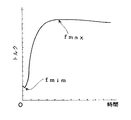
タイヤを形成するのに用いられる複数の生ゴムは、加硫温度や加硫時間等が同一条件下であっても各々の材料特性等により加硫反応状態が異なる。この加硫反応状態を定量的な加硫反応状態量として表す方法に、加硫反応状態をゴムのトルク(弾性等の力学的特性、例えばタイヤのねじれ反力)に対応させて同一条件下でトルクの変動を測定し、この特性を測定して生ゴムの加硫反応特性とする方法がある。図4には、1つの生ゴムを所定の加硫温度で加硫しながら経時的なトルク(弾性等の力学的特性)の変動を測定した場合の加硫反応特性である加硫反応曲線を示した。
【0036】
また、加硫反応曲線が以下の式(1)に示した加硫度をパラメータとする正規確率分布関数の曲線に近似する点に本発明者は着目し、タイヤの構成材料毎の加硫反応曲線を用いて、各構成材料の加硫反応特性を数式モデル化することによって定数化したタイヤの全構成材料の各加硫反応特性をデータベース化した。図5には、トルクが最大になるまでの加硫反応曲線(図5の実線)と、正規確率分布関数の曲線(図5の点線)とを示した。
【0037】
【数1】

但し、0<t<∞
t :加硫時間
TCONST :加硫温度(一定)
t* :加硫度(以下の式(2)、アルレニウスの式から演算)
AT ,BT :物理定数
【0039】
【数2】
但し、To:標準温度
E :活性化エネルギー
R :気体定数
T :加硫温度
t :加硫時間
次に、この正規確率分布関数を変数変換して、以下の式(3)に示した対数正規確率分布関数を得る。
【0041】
【数3】
但し、AT ,BT :物理定数
η:正規確率規準化変数
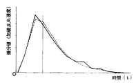
上記式(3)から、各構成材料の対数正規確率分布関数における曲線は、最小自乗法等によって、物理定数AT 、BT を係数として加硫度t* をパラメータとする直線で近似する。また、図6には、当該加硫反応曲線を有する関数を微分することによって得られる微分曲線を示した。この微分値は、加硫の進行速度(以下、加硫反応速度という)を表すと考えられ、正規確率規準化変数ηに対応する。従って、各構成材料の加硫反応速度は、式(3)の定数項の値である物理定数AT 、BT によって表現でき、この物理定数AT 、BT を構成材料毎に求めておけば加硫度に対する構成材料毎の加硫反応速度を求めることができる。従って、これらの定数AT 、BT をタイヤの構成材料の全てについて求めて、外部記憶装置82にデータベース化して記憶する。
【0043】
上記加硫反応速度の特性は、正規分布に近似できる。そこで、本発明者は、加硫時間をパラメータとして、加硫が完了(例えば、トルクが最大となる)するまでの構成材料の加硫反応速度曲線を正規分布に対応させ、加硫が完了した構成材料に対する加硫反応状態と、所定の加硫度t* の時点での加硫反応状態との比率を加硫反応率Uと定義している。
【0044】
上記で述べたように、タイヤは複数の構成材料で形成されているが、加硫反応率Uは、加硫度t* に応じて構成材料毎に求めることができる。
【0045】
この加硫反応率Uは、一定温度でのタイヤの加硫処理によって生タイヤの原料である高分子化合物間の結びつき(ポリマーと硫黄との結びつき)をイメージで表した状態(所謂、網目)の密度と見なすことができる。この加硫度t* を用いて求められる加硫反応率Uを以下の式(4)に示した。
【0046】
【数4】
図7には、3種類の構成材料を例にした加硫度と加硫反応率との対応を示した。このように加硫度が同一であっても加硫反応率が異なることが理解される。
【0048】
従って、最遅部材の加硫度−加硫反応率曲線から、現在の加硫度t* に対する加硫反応率Uを求めることで、タイヤの加硫反応状態を特定することができる。このとき、加硫が完了するまでの加硫反応率Uは求まるので、加硫時間を予測することができ、最遅部材を規準とする加硫時間を予測することができる。これによって最遅部材の加硫反応率Uが所定の加硫反応率Uを越えるまで、加硫することでタイヤの加硫を最適に制御できる。
【0049】
また、本実施例では、加硫を完了と判定するための加硫反応率Uを臨界反応値として、予め定めた臨界反応率Ubを用いている。この臨界反応率Ubは、気泡発生有無の判別点のテスト等の実験により実用上差し支えない状態まで加硫された構成材料の加硫反応率Uである。この臨界反応率Ubは、得られるタイヤが要求する加硫度等に応じて定めることができる。
【0050】
以下に本実施例の作用を説明する。本実施例では、上記の設定条件に基づいて、FEM解析によって加硫反応状態量としての加硫反応率Uを求め、この求められた加硫反応率から加硫時間を予測する。
【0051】
予測された加硫時間は、加硫機10を加硫制御している実際の加硫時間と比較され、実際の加硫時間が予測された加硫時間となったか否かが判断され、加硫機10をフィードバック制御する。この加硫機10は、予測加硫時間を経過した時点で、最適に加硫されたと判断して停止される。
【0052】
この加硫機10の加硫制御手順を、図8のフローチャートに従って詳細に説明する。ステップ102では、加硫機10によって処理されるタイヤ48の初期条件が入力され、次いでステップ104において初期境界条件が入力された後、ステップ106へ移行して加硫制御駆動装置88での加硫(加熱)を開始し、ステップ108へ移行する。
【0053】
次のステップ108、110、112では、ジャケット温度検出センサ42からの検出結果、プラテン温度検出センサ44からの検出結果及びブラダー温度検出センサ46からの検出結果をそれぞれ取り込み、ステップ114へ移行して熱伝導解析がなされる。
【0054】
ここで、熱伝導解析では、最初にFEM演算によって、前記ステップ108、110、112によって得られた温度に基づいて、タイヤ48のセンター部48A、ハンプ部48B、ビード部48Cのそれぞれの位置(合計3位置)について、タイヤ内温度を予測する。一般には、ハンプ部48Bの肉厚が最も厚いため、このハンプ部48が完全に加硫されれば、他の部位も加硫されているはずであるが、生タイヤを構成するゴムの性質やゴムの積層状態等によっては、別の部位が遅く加硫されることや同一部位内であっても加硫状態が異なることもある。そこで、本実施例では、タイヤ48のセンター部48A、ハンプ部48B、ビード部48Cのタイヤ内温度のそれぞれに基づいて、熱伝導解析が行われる。
【0055】
次のステップ116では、上記3位置のタイヤ内温度に基づいて、熱伝導の度合いが低い等のために、最も加硫が遅れる位置(最遅点)を決定する。
【0056】
次のステップ117では、決定された最遅点について熱伝導解析によって得られた予測温度から加硫度t* を求める(式(2)参照)。また、決定された最遅点における各構成材料について、加硫反応速度を表す定数AT 、BT を外部記憶装置から読み取りかつ、読み取った定数AT 、BT を用いて各構成材料の加硫反応率Uを求める。
【0057】
次のステップ118では、求めた各構成材料の加硫反応率Uに基づいて、加硫が完了するまでの加硫予測時間tF を演算する。すなわち、臨界反応率Ubを読み取って、最遅点における加硫度t* に対する各構成材料の加硫反応率Uと、読み取った臨界反応率Ubとの差を求める。この差が最大の構成材料が最も未加硫に近い構成材料であるので、この構成材料の加硫反応率Uが臨界反応率Ubに到達するときの到達加硫度を求める。この到達加硫度と現在の加硫度とから最遅点の全ての構成材料が臨界反応率Ubに到達するまでの、すなわち、加硫が完了するまでの加硫予測時間tF を演算する。
【0058】
次のステップ120では、加硫制御駆動装置88によって制御されている実際の加硫時間tR が読み込まれ、ステップ122において、実際の加硫時間tR と加硫予測時間tF とが比較される。
【0059】
ステップ122でtR <tF と判定された場合は、設定された加硫反応状態に到達していないと判断され、ステップ106へ移行して各部の温度を検出すると共に熱伝導解析を行う(ステップ106〜120)。このように、推定された加硫時間に到達するまで、逐次FEM解析が行われ、逐次最適な加硫時間が求められる。
【0060】
また、ステップ122でtR ≧tF と判定された場合は、設定された加硫反応状態に達したと判断され、ステップ124へ移行して加硫制御を停止し、処理は終了する。
【0061】
従来の加硫機でタイヤをテスト加硫等のデータに基づいて加硫制御した場合を100として、本実施例の加硫反応率を判断基準としたシステムを適用した場合の比較値を以下の表1に示した。
【0062】
【表1】
但し、品質には、ドラム耐久性や耐磨耗性を含んでいる。
このように、FEM解析によってタイヤの温度を予測すると共に予測された温度から得られる加硫度と、タイヤの構成材料毎に求めた加硫反応率とによって加硫中の加硫反応状態を特定して加硫時間を制御するようにしたので、同一ロット間でばらつきなく加硫されたタイヤを得ることができると共に、構成材料の要素変更が生じた場合でも当該加硫機により加硫されたタイヤの加硫反応状態もばらつきなく加硫されたタイヤを得ることができる。従って、高い品質のタイヤを安定して供給することができる加硫機を実現することができる。
【0064】
なお、上記実施例では、一定の加硫温度の下で加硫時間の変更によってタイヤに供給する加硫時のエネルギーとしたが、加硫温度を変更して加硫時のエネルギーを制御するようにしてもよい。
【0065】
【発明の効果】
以上説明したように本発明によれば、加硫処理中においてタイヤ等の被加硫材料を構成する構成材料の各々について加硫反応状態を把握することができ、この加硫反応状態の量を判断因子として加硫制御しているため、被加硫材料個々に最適な加硫条件を設定できるまたは最適なエネルギーを供給でき、安定した品質で加硫された被加硫材料を提供することができる、という効果がある。
【図面の簡単な説明】
【図1】本実施例が適用された加硫機の内部構造を示す概略図である。
【図2】タイヤの軸方向断面図である。
【図3】制御装置の概略構成を示すブロック図である。
【図4】所定加硫温度で加硫するときの加硫時間とトルクとの関係を表す加硫反応曲線を示す線図である。
【図5】図4の最大トルクまでを示す線図である。
【図6】図5の微分特性を示す線図である。
【図7】加硫度と加硫反応率との関係を表す線図である。
【図8】本実施例の加硫機における加硫制御の流れを示すフローチャートである。
【符号の説明】
10 加硫機
48 タイヤ
70 制御装置
82 外部記憶装置[0001]
[Industrial applications]
The present invention relates to a vulcanization control method and a vulcanization system, and more particularly to a vulcanization control method and a vulcanization system for vulcanizing a material to be vulcanized, such as rubber or plastic, for example, a tire by a vulcanizer.
[0002]
[Prior art]
Conventionally, the processing conditions (temperature and time) for vulcanizing a tire are as follows: several raw tires are sampled from a production lot to be vulcanized, and the raw tires are loaded into a vulcanizer at a predetermined temperature and a predetermined temperature. , And a predetermined vulcanization time, test vulcanization is performed, and the internal temperature of the tire is measured to determine the degree of vulcanization, which is determined based on this. That is, vulcanization is performed while measuring the temperature with one or several tires in the same lot to determine the optimum processing conditions, and thereafter vulcanization processing is performed on the remaining tires in the same lot as fixed processing conditions. .
[0003]
The treatment conditions for the vulcanization treatment must take into account various factors of variation, and are set to have a high safety factor. Factors of this variation include tire gauge and bladder conditions, rubber vulcanization rate variation, green tire temperature variation, ambient temperature variation, mold temperature, heat source variation, and the like.
[0004]
If vulcanization is carried out under processing conditions with a high safety factor, the vulcanization time will be lengthened substantially, leading to a reduction in treatment efficiency. As a countermeasure, it is proposed to predict the temperature inside the tire by numerical calculation. (See Japanese Patent Publication No. 4-73683 and Japanese Patent Application Laid-Open No. 1-121311).
[0005]
[Problems to be solved by the invention]
However, even if vulcanization is performed based on the results of test vulcanization or a temperature predicted by numerical calculation, it is not possible to eliminate variations in vulcanization due to variations in individual materials in the same lot. Therefore, in order to reduce unvulcanized tires in each lot, the safety factor must be increased. For this reason, the obtained tire includes an optimally vulcanized tire and an over-vulcanized tire.
[0006]
In view of the above facts, the present invention provides a vulcanization control method and a vulcanization control method that can optimally vulcanize a tire without vulcanization or over-vulcanization when vulcanizing a material to be vulcanized such as a tire. The aim is to obtain a sulfur system.
[0007]
[Means for Solving the Problems]
In order to achieve the above object, in the vulcanization control method of the present invention, for each of a plurality of constituent materials constituting the material to be vulcanized, the vulcanization reaction characteristics representing the relationship between the applied energy and the amount of vulcanization reaction are determined. obtained in advance measured physical quantity that affects at least the vulcanization reaction associated with the vulcanization reaction rate based on vulcanized reaction characteristics in advance, for each of the plurality of positions determined in advance for the object to be vulcanized materials, time during vulcanization heat source and the estimated temperature based on the temperature at which the temperature was estimated estimate the internal temperature was measured a plurality of positions a predetermined said performing heat transfer analysis using thermal energy which the vulcanized material undergoes a series heating device The degree of vulcanization of the material to be vulcanized to be vulcanized with the energy applied by the vulcanization is determined, and the vulcanization degree at the plurality of positions is determined based on the determined degree of vulcanization and the physical quantity related to the vulcanization reaction rate. Asked, all asked The energy applied to the vulcanized material to the amount vulcanization reaction state is predetermined value determined, until vulcanization reaction conditions of a plurality of positions of said predetermined by the determined energy is the predetermined value of Vulcanization control is performed so that vulcanization occurs.
[0008]
Further, in the vulcanization system of the present invention, for each of a plurality of constituent materials constituting the material to be vulcanized, a vulcanization reaction characteristic representing a relationship between an applied energy and a vulcanization reaction amount is measured in advance and the vulcanization reaction is performed. A step of previously obtaining a physical quantity related to the vulcanization reaction rate based on the reaction characteristic; a step of storing the obtained physical quantity in a storage device; and a time-series process during vulcanization for each of the plurality of positions of the material to be vulcanized. Measuring the boundary temperature of the material to be vulcanized, performing heat conduction analysis using the measured boundary temperature to estimate the temperature at the plurality of positions, and determining the degree of vulcanization based on the estimated temperature; A step of obtaining the vulcanization reaction state quantity at the plurality of positions based on the physical quantity read and read from the storage device and reading the physical quantity corresponding to each of the constituent materials included in each of the positions, and the obtained degree of vulcanization. , All you asked Vulcanization reaction state quantity contains a step of determining the energy applied to the vulcanized material until the predetermined value, and controlling vulcanized by the determined energy, a.
[0009]
Note that a tire can be used as the material to be vulcanized.
[0010]
[Action]
In the vulcanization control method of the present invention, for each of a plurality of constituent materials constituting the material to be vulcanized, a vulcanization representing a relationship between added energy obtained from a vulcanization temperature and a vulcanization time and a vulcanization reaction amount. The vulcanization reaction characteristics are measured in advance, and a physical quantity related to the vulcanization reaction rate is previously determined based on the vulcanization reaction characteristics. As the material to be vulcanized, a material such as rubber or plastic can be used, and a tire can be used as described in
[0011]
For each of the plurality of positions of the material to be vulcanized, a boundary temperature of the material to be vulcanized is measured in time series during vulcanization, and a heat conduction analysis is performed using the measured boundary temperature to perform the heat conduction analysis. The temperature is estimated and the degree of vulcanization is determined based on the estimated temperature. The temperature can be estimated by using the finite element method. The heat conduction analysis using the finite element method allows the temperature inside the material to be vulcanized to reach a predetermined position inside the material to be vulcanized without contacting the material to be vulcanized. Can be accurately estimated, and the degree of vulcanization at each of the plurality of positions can be obtained.
[0012]
Next, vulcanization reaction state quantities at the plurality of positions are determined based on the determined degree of vulcanization and physical quantities related to the vulcanization reaction rate. This vulcanization reaction state quantity represents the degree of the vulcanization reaction in the course of vulcanization, and is obtained from the previously measured vulcanization reaction characteristics of each constituent material constituting the material to be vulcanized. It can be determined for each constituent material using a physical quantity related to the vulcanization reaction rate.
[0013]
Next, the energy to be applied to the material to be vulcanized, which is obtained from the vulcanization temperature and the vulcanization time until all the obtained vulcanization reaction state quantities reach a predetermined value, is determined. As the predetermined value, a critical reaction value (for example, a value until vulcanization proceeds and no bubbles are generated in the rubber) can be used. The energy used is the energy until the amount of the vulcanization reaction state calculated for the latest vulcanization point reaches a predetermined critical reaction value. Since the vulcanization latest point is the position where vulcanization is delayed most, if the energy to be supplied to this vulcanization latest point is obtained, the energy to be supplied to other positions will be included.
[0014]
If vulcanized materials such as tires are vulcanized with the obtained energy, each vulcanized material can be converted to the minimum energy (optimum) without generating unvulcanized parts that have not been vulcanized to a desired vulcanized state. Vulcanization conditions).
[0015]
As described above, the vulcanization control of the material to be vulcanized is performed by obtaining the amount of the vulcanization reaction state for each constituent material at a plurality of positions and further obtaining the energy up to a predetermined value (critical reaction value). Regarding each vulcanized material to be vulcanized, the vulcanization can be performed optimally even when the characteristics of the constituent materials differ between lots or over time.
[0016]
Further, in the vulcanization system of the present invention, a post-process for actually vulcanizing the material to be vulcanized and a pre-process before performing the vulcanization treatment can be roughly classified. As this pre-process, for each of a plurality of constituent materials constituting the material to be vulcanized, vulcanization reaction characteristics representing the relationship between the applied energy and the amount of vulcanization reaction are measured in advance and based on the vulcanization reaction characteristics. The method includes a step of obtaining a physical quantity related to the vulcanization reaction rate in advance, and a step of storing the obtained physical quantity in a storage device. This physical quantity is obtained for each of a plurality of constituent materials constituting the material to be vulcanized, but the composition may be different even for the same type of constituent materials, so when the lots are different or when the production lots are different. Also determines the physical quantity. Therefore, when the combination of a plurality of constituent materials is made different when the material to be vulcanized is manufactured, different characteristics may be obtained depending on the combination. Therefore, it is preferable to obtain the physical quantity. The physical quantity is also obtained when the characteristics are expected to be different due to aging. As a result, the storage device accumulates physical quantities that are compositions or characteristics when the material to be vulcanized is actually vulcanized.
[0017]
In the post-process, for each of the multiple positions of the material to be vulcanized, the boundary temperature of the material to be vulcanized is measured in a time series during the vulcanization, and the heat conduction analysis is performed using the measured boundary temperature, and the multiple positions of the multiple positions are determined A step of estimating the temperature and obtaining the degree of vulcanization based on the estimated temperature, and for each of the plurality of positions, reading and reading a physical amount corresponding to each of the constituent materials included from the storage device, and the obtained degree of vulcanization A step of calculating the amount of vulcanization reaction state at a plurality of positions on the basis of, and a step of obtaining energy to be applied to the material to be vulcanized until all the obtained vulcanization reaction state quantities reach a predetermined value. Controlling vulcanization by energy.
[0018]
As described above, in the post-process, the physical quantity corresponding to the constituent material constituting the material to be vulcanized to be actually vulcanized, which is obtained in the previous process, is read from the storage device and used. The amount of vulcanization reaction state of the material and the energy applied to the material to be vulcanized can be accurately obtained. Accordingly, the vulcanization of the material to be vulcanized is controlled by the energy until the amount of the vulcanization reaction state at a plurality of positions reaches a predetermined value (critical reaction value). Even when the properties of the materials are different, vulcanization can be performed optimally.
[0019]
【Example】
FIG. 1 shows an embodiment of a vulcanizer 10 to which the present invention is applied.
[0020]
The vulcanizer 10 includes a
[0021]
The
[0022]
In addition, an
[0023]
[0024]
The
[0025]
Pipes 36 and 38 for circulating a heating fluid such as steam, gas and hot water are connected to the lower ring 30 via the
[0026]
In this embodiment, three temperature sensors are provided in the vulcanizer 10 having the above configuration. The first temperature sensor is a jacket
[0027]
These
[0028]
Further, as shown in FIG. 2, in estimating the temperature in the
[0029]
As shown in FIG. 3, the
[0030]
The input /
[0031]
The
[0032]
The initial condition is a temperature before vulcanization, that is, an initial temperature of the green tire, and the like, which is detected by a temperature sensor (not shown) provided outside the vulcanizer 10. The initial boundary condition is a boundary condition that does not change with time, such as thermal conductivity of rubber and internal heat generation, related to the physical properties of the tire.
[0033]
Further, the temperature inside the tire is not actually detected, but based on the temperature from the jacket
[0034]
Here, the principle of optimizing the vulcanization energy (vulcanization time in the present embodiment) based on the vulcanization control of the tire in this embodiment will be described.
[0035]
A plurality of raw rubbers used to form a tire have different vulcanization reaction states depending on their material properties and the like even under the same vulcanization temperature and vulcanization time. In a method of expressing this vulcanization reaction state as a quantitative vulcanization reaction state quantity, the vulcanization reaction state is made to correspond to rubber torque (dynamic characteristics such as elasticity, for example, torsional reaction force of a tire) under the same conditions. There is a method in which a fluctuation in torque is measured, and this characteristic is measured to obtain a vulcanization reaction characteristic of raw rubber. FIG. 4 shows a vulcanization reaction curve which is a vulcanization reaction characteristic when a change in torque (mechanical characteristics such as elasticity) with time is measured while vulcanizing one raw rubber at a predetermined vulcanization temperature. Was.
[0036]
Further, the present inventor pays attention to the point that the vulcanization reaction curve approximates to a curve of a normal probability distribution function using the degree of vulcanization as a parameter as shown in the following equation (1), and the vulcanization reaction Using the curves, the vulcanization reaction characteristics of all the constituent materials of the tire, which were converted into constants by modeling the vulcanization reaction characteristics of the respective constituent materials into mathematical models, were compiled into a database. FIG. 5 shows a vulcanization reaction curve up to the maximum torque (solid line in FIG. 5) and a curve of the normal probability distribution function (dotted line in FIG. 5).
[0037]
(Equation 1)
However, 0 <t <∞
t: vulcanization time T CONST : vulcanization temperature (constant)
t * : Vulcanization degree (calculated from the following equation (2), Arlenius equation)
A T , B T : Physical constant
(Equation 2)
Here, To: standard temperature E: activation energy R: gas constant T: vulcanization temperature t: vulcanization time Next, this normal probability distribution function is transformed into a variable, and the logarithmic normal shown in the following equation (3) is obtained. Obtain the probability distribution function.
[0041]
(Equation 3)
However, A T, B T: physical constants eta: from normal random normalized variables above formula (3), the curves in the logarithmic normal probability distribution function of each constituent material, by the least square method or the like, physical constants A T, B T Is approximated by a straight line with the vulcanization degree t * as a parameter using FIG. 6 shows a differential curve obtained by differentiating a function having the vulcanization reaction curve. This differential value is considered to represent a vulcanization progress rate (hereinafter, referred to as a vulcanization reaction rate), and corresponds to a normal probability normalization variable η. Therefore, the vulcanization kinetics of each constituent material, physical constants A T is the value of the constant term of the equation (3) can be represented by B T, the physical constants A T, Oke seeking B T for each constituent material For example, the vulcanization reaction rate for each constituent material with respect to the degree of vulcanization can be determined. Thus, these constants A T, the B T asking for all of the constituent materials of the tire, and stores the database in the
[0043]
The characteristics of the vulcanization reaction rate can be approximated to a normal distribution. Then, the inventor sets the vulcanization reaction speed curve of the constituent material until vulcanization is completed (for example, the torque becomes maximum) with the vulcanization time as a parameter and corresponds to a normal distribution, and vulcanization is completed. The ratio of the vulcanization reaction state for the constituent material to the vulcanization reaction state at the time of the predetermined degree of vulcanization t * is defined as the vulcanization reaction rate U.
[0044]
As described above, the tire is formed of a plurality of constituent materials, but the vulcanization reaction rate U can be determined for each constituent material according to the degree of vulcanization t * .
[0045]
The vulcanization reaction rate U is a state (so-called mesh) in which a bond between a high molecular compound as a raw material of a raw tire (bond between a polymer and sulfur) is represented by an image by vulcanizing a tire at a constant temperature. It can be considered as density. The vulcanization reaction rate U determined using this degree of vulcanization t * is shown in the following equation (4).
[0046]
(Equation 4)
FIG. 7 shows the correspondence between the degree of vulcanization and the degree of vulcanization reaction using three types of constituent materials as examples. Thus, it is understood that the vulcanization reaction rates are different even when the degree of vulcanization is the same.
[0048]
Therefore, the vulcanization reaction state of the tire can be specified by obtaining the vulcanization reaction rate U for the current vulcanization degree t * from the vulcanization degree-vulcanization reaction rate curve of the slowest member. At this time, since the vulcanization reaction rate U until vulcanization is completed is determined, the vulcanization time can be predicted, and the vulcanization time based on the slowest member can be predicted. Thereby, vulcanization is performed until the vulcanization reaction rate U of the slowest member exceeds a predetermined vulcanization reaction rate U, so that vulcanization of the tire can be optimally controlled.
[0049]
Further, in this embodiment, a predetermined critical reaction rate Ub is used as a vulcanization reaction rate U for determining that vulcanization is completed as a critical reaction value. The critical reaction rate Ub is a vulcanization reaction rate U of a constituent material that has been vulcanized to a practically acceptable state by an experiment such as a test of a determination point for the presence or absence of bubbles. The critical reaction rate Ub can be determined according to the degree of vulcanization required for the obtained tire.
[0050]
The operation of the present embodiment will be described below. In this embodiment, a vulcanization reaction rate U as a vulcanization reaction state quantity is obtained by FEM analysis based on the above set conditions, and a vulcanization time is predicted from the obtained vulcanization reaction rate.
[0051]
The predicted vulcanization time is compared with the actual vulcanization time that controls vulcanization of the vulcanizer 10, and it is determined whether or not the actual vulcanization time has reached the predicted vulcanization time. The sulfurizer 10 is feedback-controlled. When the predicted vulcanization time has elapsed, the vulcanizer 10 is determined to be optimally vulcanized and is stopped.
[0052]
The vulcanization control procedure of the vulcanizer 10 will be described in detail with reference to the flowchart of FIG. In
[0053]
In the following
[0054]
Here, in the heat conduction analysis, the respective positions (total of the
[0055]
In the
[0056]
In the
[0057]
In the next step 118, based on the vulcanization reaction rate U of the constituent material obtained, it calculates the vulcanization prediction time t F until vulcanization is complete. That is, the critical reaction rate Ub is read, and the difference between the vulcanization reaction rate U of each constituent material with respect to the degree of vulcanization t * at the latest point and the read critical reaction rate Ub is obtained. Since the constituent material having the largest difference is the constituent material closest to the unvulcanized state, the ultimate degree of vulcanization when the vulcanization reaction rate U of this constituent material reaches the critical reaction rate Ub is determined. From this arrival vulcanization degree and the current degree of vulcanization to all of the material of the slowest point reaches the critical reaction rate Ub, i.e., calculates the vulcanization prediction time t F until the vulcanization completed .
[0058]
In the next step 120, it is read actual vulcanization time t R which is controlled by the pressurized硫制
[0059]
If it is determined that t R <t F at
[0060]
If it is determined in
[0061]
When the vulcanization control is performed based on data such as test vulcanization of a tire with a conventional vulcanizer, the comparison value when the system using the vulcanization reaction rate of the present embodiment as a criterion is set to 100, where The results are shown in Table 1.
[0062]
[Table 1]
However, the quality includes drum durability and abrasion resistance.
As described above, the tire temperature is predicted by the FEM analysis, and the vulcanization degree obtained from the predicted temperature and the vulcanization reaction state determined for each constituent material of the tire are used to specify the vulcanization reaction state during vulcanization. As the vulcanization time is controlled, it is possible to obtain a vulcanized tire without variation between the same lots, and vulcanized by the vulcanizer even when an element of a constituent material is changed. A vulcanized tire can be obtained without variation in the vulcanization reaction state of the tire. Accordingly, it is possible to realize a vulcanizer capable of stably supplying high-quality tires.
[0064]
In the above embodiment, the energy at the time of vulcanization supplied to the tire by changing the vulcanization time under a certain vulcanization temperature is used. However, the energy at the time of vulcanization is controlled by changing the vulcanization temperature. It may be.
[0065]
【The invention's effect】
As described above, according to the present invention, it is possible to grasp the vulcanization reaction state of each of the constituent materials constituting the material to be vulcanized such as a tire during the vulcanization treatment, and determine the amount of the vulcanization reaction state. Since vulcanization is controlled as a judgment factor, it is possible to set optimal vulcanization conditions for each material to be vulcanized or to supply optimal energy, and to provide a material to be vulcanized with stable quality. There is an effect that can be.
[Brief description of the drawings]
FIG. 1 is a schematic diagram showing an internal structure of a vulcanizer to which the present embodiment is applied.
FIG. 2 is an axial sectional view of a tire.
FIG. 3 is a block diagram illustrating a schematic configuration of a control device.
FIG. 4 is a diagram showing a vulcanization reaction curve showing the relationship between vulcanization time and torque when vulcanizing at a predetermined vulcanization temperature.
FIG. 5 is a diagram showing up to the maximum torque of FIG. 4;
FIG. 6 is a diagram showing a differential characteristic of FIG. 5;
FIG. 7 is a diagram showing a relationship between a degree of vulcanization and a vulcanization reaction rate.
FIG. 8 is a flowchart showing a flow of vulcanization control in the vulcanizer of the present embodiment.
[Explanation of symbols]
10
Claims (3)
前記被加硫材料について予め定めた複数位置の各々について、加硫中に時系列的に加熱装置の熱源とその内部温度を計測し被加硫材料が受ける熱エネルギーを用い熱伝導解析を行って前記予め定めた複数位置の温度を推定し推定した温度に基づいて該推定温度により加えられるエネルギーで加硫されるべき被加硫材料の加硫度を求め、
求めた加硫度と、前記加硫反応速度に関連した物理量とに基づいて前記複数位置の加硫反応状態量を求め、
求めた全ての加硫反応状態量が予め定めた所定値になるまでの被加硫材料に加えるエネルギーを求め、
その求めたエネルギーにより前記予め定めた複数位置の加硫反応状態量が前記所定値になるまで加硫するように加硫制御する、
加硫制御方法。For each of a plurality of constituent materials constituting the material to be vulcanized, vulcanization reaction characteristics representing the relationship between the applied energy and the amount of vulcanization reaction are measured in advance, and the vulcanization reaction rate is determined based on the vulcanization reaction characteristics. Determine at least relevant physical quantities that affect the vulcanization reaction in advance,
For each of a plurality of positions predetermined for the material to be vulcanized, the heat source of the heating device and the internal temperature thereof are measured in time series during vulcanization, and a heat conduction analysis is performed using the heat energy received by the material to be vulcanized. The vulcanization degree of the material to be vulcanized to be vulcanized with the energy added by the estimated temperature is estimated based on the temperature estimated at the plurality of predetermined positions and estimated .
Determined vulcanization degree, the vulcanization reaction state quantity at the plurality of positions based on the physical quantity related to the vulcanization reaction rate,
Determine the energy to be applied to the material to be vulcanized until all the obtained vulcanization reaction state quantities reach a predetermined value,
The vulcanization control is performed so that the vulcanization reaction state quantity at the plurality of predetermined positions is vulcanized by the obtained energy until the vulcanization reaction state quantity reaches the predetermined value .
Vulcanization control method.
求めた物理量を記憶装置に蓄積する工程と、
前記被加硫材料の複数位置の各々について、加硫中に時系列的に被加硫材料の境界温度を計測し計測された該境界温度を用いて熱伝導解析を行って前記複数位置の温度を推定し推定した温度に基づいて加硫度を求める工程と、
前記複数位置の各々について、含まれる前記構成材料の各々に該当する前記物理量を前記記憶装置から読み取り読み取った物理量と、求めた加硫度とに基づいて前記複数位置の加硫反応状態量を求める工程と、
求めた全ての加硫反応状態量が予め定めた所定値になるまでの被加硫材料に加えるエネルギーを求める工程と、
その求めたエネルギーにより加硫制御する工程と、
を含む加硫システム。For each of a plurality of constituent materials constituting the material to be vulcanized, vulcanization reaction characteristics representing the relationship between the applied energy and the amount of vulcanization reaction are measured in advance, and the vulcanization reaction rate is determined based on the vulcanization reaction characteristics. A step of previously determining a related physical quantity;
Storing the obtained physical quantity in a storage device;
For each of the plurality of positions of the material to be vulcanized, the boundary temperature of the material to be vulcanized is measured in a time series during vulcanization, and a heat conduction analysis is performed using the measured boundary temperature, and the temperature at the plurality of positions is determined. Estimating the degree of vulcanization based on the estimated temperature,
For each of the plurality of positions, the vulcanization reaction state quantity at the plurality of positions is obtained based on the physical amount obtained by reading and reading the physical amount corresponding to each of the contained constituent materials from the storage device and the obtained degree of vulcanization. Process and
A step of obtaining energy to be applied to the material to be vulcanized until all the obtained vulcanization reaction state quantities reach a predetermined value,
A step of controlling vulcanization by the obtained energy;
Including vulcanization system.
Priority Applications (1)
| Application Number | Priority Date | Filing Date | Title |
|---|---|---|---|
| JP15960293A JP3549552B2 (en) | 1993-06-29 | 1993-06-29 | Vulcanization control method and vulcanization system |
Applications Claiming Priority (1)
| Application Number | Priority Date | Filing Date | Title |
|---|---|---|---|
| JP15960293A JP3549552B2 (en) | 1993-06-29 | 1993-06-29 | Vulcanization control method and vulcanization system |
Publications (2)
| Publication Number | Publication Date |
|---|---|
| JPH079457A JPH079457A (en) | 1995-01-13 |
| JP3549552B2 true JP3549552B2 (en) | 2004-08-04 |
Family
ID=15697294
Family Applications (1)
| Application Number | Title | Priority Date | Filing Date |
|---|---|---|---|
| JP15960293A Expired - Fee Related JP3549552B2 (en) | 1993-06-29 | 1993-06-29 | Vulcanization control method and vulcanization system |
Country Status (1)
| Country | Link |
|---|---|
| JP (1) | JP3549552B2 (en) |
Families Citing this family (5)
| Publication number | Priority date | Publication date | Assignee | Title |
|---|---|---|---|---|
| US20080023917A1 (en) * | 2006-07-28 | 2008-01-31 | Hydril Company Lp | Seal for blowout preventer with selective debonding |
| JP5966335B2 (en) * | 2011-12-02 | 2016-08-10 | 横浜ゴム株式会社 | Simulation method, vulcanization control method, and computer program for simulation |
| JP5732026B2 (en) * | 2012-12-06 | 2015-06-10 | 住友ゴム工業株式会社 | Method for predicting the degree of vulcanization of rubber materials |
| JP6465731B2 (en) * | 2015-04-22 | 2019-02-06 | Toyo Tire株式会社 | Pneumatic tire manufacturing method and pneumatic tire |
| JP6737075B2 (en) * | 2016-08-30 | 2020-08-05 | 住友ゴム工業株式会社 | Method for calculating a crosslinking reaction rate of a crosslinking reaction involving a vulcanization accelerator and a crosslinking agent in a rubber composition containing the vulcanization accelerator and the crosslinking agent |
Family Cites Families (15)
| Publication number | Priority date | Publication date | Assignee | Title |
|---|---|---|---|---|
| JPS58168541A (en) * | 1982-03-31 | 1983-10-04 | Mitsubishi Heavy Ind Ltd | Metal mold heating controlling device for vulcanizer |
| JPS5962131A (en) * | 1982-10-01 | 1984-04-09 | Bridgestone Corp | Control on vulcanization of tire |
| JPS59199234A (en) * | 1983-04-28 | 1984-11-12 | Bando Chem Ind Ltd | Control of rubber vulcanizing process |
| DE3320963C2 (en) * | 1983-06-10 | 1986-04-10 | Continental Gummi-Werke Ag, 3000 Hannover | Method and device for vulcanizing pneumatic tires |
| JPS6013250A (en) * | 1983-07-01 | 1985-01-23 | Bando Chem Ind Ltd | Controlling method of rubber vulcanization process |
| JPS6315708A (en) * | 1986-07-07 | 1988-01-22 | Bridgestone Corp | Method for controlling tyre vulcanization |
| JPS63139708A (en) * | 1986-12-02 | 1988-06-11 | Bridgestone Corp | Method and apparatus for controlling vulcanization of tire |
| JPS63111017A (en) * | 1986-10-28 | 1988-05-16 | Bridgestone Corp | Control method for type vulcanization |
| JPS63209817A (en) * | 1987-02-25 | 1988-08-31 | Bridgestone Corp | Control method of vulcanization |
| JPH01113211A (en) * | 1987-10-28 | 1989-05-01 | Bridgestone Corp | Measurement of internal temperature of vulcanized object and control of tire vulcanization |
| JPH072368B2 (en) * | 1989-05-31 | 1995-01-18 | 理化工業株式会社 | Motor control device for extrusion molding line |
| JPH06226747A (en) * | 1991-10-31 | 1994-08-16 | Sumitomo Rubber Ind Ltd | Dome type tire vulcanizer |
| JP3233984B2 (en) * | 1992-05-26 | 2001-12-04 | エヌオーケー株式会社 | Vulcanizer temperature controller |
| JP3234001B2 (en) * | 1992-08-31 | 2001-12-04 | エヌオーケー株式会社 | Vulcanizer temperature controller |
| JPH06297460A (en) * | 1993-04-12 | 1994-10-25 | Bridgestone Corp | Tire vulcanizing controlling method |
-
1993
- 1993-06-29 JP JP15960293A patent/JP3549552B2/en not_active Expired - Fee Related
Also Published As
| Publication number | Publication date |
|---|---|
| JPH079457A (en) | 1995-01-13 |
Similar Documents
| Publication | Publication Date | Title |
|---|---|---|
| JP3698804B2 (en) | Method and apparatus for forming a database of vulcanization constants to optimize vulcanization of rubber compounds | |
| US6490501B1 (en) | Cure monitoring and control system | |
| JP2006281662A (en) | Controller device of injection molding machine | |
| JP3549552B2 (en) | Vulcanization control method and vulcanization system | |
| JP7293962B2 (en) | Molded product quality anomaly prediction system | |
| JPH0740355A (en) | Vulcanization control method | |
| Han et al. | Optimal curing of rubber compounds with reversion type cure behavior | |
| JP2007098756A (en) | Vulcanization control method and control system | |
| Hassan et al. | Model reference optimal steady‐state adaptive computer control of plastics extrusion processes | |
| JPH01113211A (en) | Measurement of internal temperature of vulcanized object and control of tire vulcanization | |
| JPS63209817A (en) | Control method of vulcanization | |
| KR100876437B1 (en) | Green tire vulcanization device and vulcanization method | |
| JP2023017386A (en) | Molding condition adjustment method, computer program, molding condition adjustment device and injection molding machine | |
| JPH0780843A (en) | Vulcanization control method | |
| JPS6315708A (en) | Method for controlling tyre vulcanization | |
| JP2006341471A (en) | Vulcanization system and vulcanization control method | |
| JPH06297460A (en) | Tire vulcanizing controlling method | |
| JPS63139708A (en) | Method and apparatus for controlling vulcanization of tire | |
| JPS63111017A (en) | Control method for type vulcanization | |
| JP3234001B2 (en) | Vulcanizer temperature controller | |
| JP3455919B2 (en) | Vulcanizer temperature controller | |
| JP7725704B2 (en) | Hybrid manufacturing of 3D parts | |
| JP3382685B2 (en) | Vulcanizer mold temperature controller | |
| JP2016221895A (en) | Tire vulcanization device | |
| CN120816764B (en) | Tire vulcanization adjusting method and device |
Legal Events
| Date | Code | Title | Description |
|---|---|---|---|
| TRDD | Decision of grant or rejection written | ||
| A01 | Written decision to grant a patent or to grant a registration (utility model) |
Free format text: JAPANESE INTERMEDIATE CODE: A01 Effective date: 20040420 |
|
| A61 | First payment of annual fees (during grant procedure) |
Free format text: JAPANESE INTERMEDIATE CODE: A61 Effective date: 20040421 |
|
| R150 | Certificate of patent (=grant) or registration of utility model |
Free format text: JAPANESE INTERMEDIATE CODE: R150 |
|
| R250 | Receipt of annual fees |
Free format text: JAPANESE INTERMEDIATE CODE: R250 |
|
| FPAY | Renewal fee payment (prs date is renewal date of database) |
Free format text: PAYMENT UNTIL: 20090430 Year of fee payment: 5 |
|
| FPAY | Renewal fee payment (prs date is renewal date of database) |
Free format text: PAYMENT UNTIL: 20090430 Year of fee payment: 5 |
|
| FPAY | Renewal fee payment (prs date is renewal date of database) |
Free format text: PAYMENT UNTIL: 20100430 Year of fee payment: 6 |
|
| FPAY | Renewal fee payment (prs date is renewal date of database) |
Free format text: PAYMENT UNTIL: 20110430 Year of fee payment: 7 |
|
| FPAY | Renewal fee payment (prs date is renewal date of database) |
Free format text: PAYMENT UNTIL: 20120430 Year of fee payment: 8 |
|
| FPAY | Renewal fee payment (prs date is renewal date of database) |
Free format text: PAYMENT UNTIL: 20130430 Year of fee payment: 9 |
|
| LAPS | Cancellation because of no payment of annual fees |