JP3548552B2 - Charger and charging method - Google Patents

Charger and charging method Download PDF

Info

Publication number
JP3548552B2
JP3548552B2 JP2001276255A JP2001276255A JP3548552B2 JP 3548552 B2 JP3548552 B2 JP 3548552B2 JP 2001276255 A JP2001276255 A JP 2001276255A JP 2001276255 A JP2001276255 A JP 2001276255A JP 3548552 B2 JP3548552 B2 JP 3548552B2
Authority
JP
Japan
Prior art keywords
voltage
charging
battery
terminal
detecting
Prior art date
Legal status (The legal status is an assumption and is not a legal conclusion. Google has not performed a legal analysis and makes no representation as to the accuracy of the status listed.)
Expired - Fee Related
Application number
JP2001276255A
Other languages
Japanese (ja)
Other versions
JP2002165381A (en
Inventor
利征 原
由隆 清水
誠 日野原
Current Assignee (The listed assignees may be inaccurate. Google has not performed a legal analysis and makes no representation or warranty as to the accuracy of the list.)
Canon Inc
Original Assignee
Canon Inc
Priority date (The priority date is an assumption and is not a legal conclusion. Google has not performed a legal analysis and makes no representation as to the accuracy of the date listed.)
Filing date
Publication date
Application filed by Canon Inc filed Critical Canon Inc
Priority to JP2001276255A priority Critical patent/JP3548552B2/en
Publication of JP2002165381A publication Critical patent/JP2002165381A/en
Application granted granted Critical
Publication of JP3548552B2 publication Critical patent/JP3548552B2/en
Anticipated expiration legal-status Critical
Expired - Fee Related legal-status Critical Current

Links

Images

Classifications

    • YGENERAL TAGGING OF NEW TECHNOLOGICAL DEVELOPMENTS; GENERAL TAGGING OF CROSS-SECTIONAL TECHNOLOGIES SPANNING OVER SEVERAL SECTIONS OF THE IPC; TECHNICAL SUBJECTS COVERED BY FORMER USPC CROSS-REFERENCE ART COLLECTIONS [XRACs] AND DIGESTS
    • Y02TECHNOLOGIES OR APPLICATIONS FOR MITIGATION OR ADAPTATION AGAINST CLIMATE CHANGE
    • Y02EREDUCTION OF GREENHOUSE GAS [GHG] EMISSIONS, RELATED TO ENERGY GENERATION, TRANSMISSION OR DISTRIBUTION
    • Y02E60/00Enabling technologies; Technologies with a potential or indirect contribution to GHG emissions mitigation
    • Y02E60/10Energy storage using batteries

Landscapes

  • Charge And Discharge Circuits For Batteries Or The Like (AREA)
  • Secondary Cells (AREA)
  • Tests Of Electric Status Of Batteries (AREA)

Description

【0001】
【発明の属する技術分野】
本発明は二次電池の充電を制御する充電器および充電方法に関する。
【0002】
【従来の技術】
従来、ニッカド電池やニッケル水素電池などの二次電池の充電を制御する充電器として、満充電時における電池の温度上昇率から充電完了を検出するいわゆるΔT検出方式のものと、満充電時における電池の電圧降下から充電完了を検出するいわゆるΔV検出方式のものが知られている。
【0003】
例えば、図27に示すようにΔT検出方式の充電器100は定電圧電源106、定電流回路101、CPU105およびA/Dコンバータ102を有し、接続された電池パック107に定電流回路101から一定の充電電流を供給する。電池パック107は数本の電池103とサーミスタ104を組み合わせて一体化されたものであり、電池103の外装表面に取り付けられたサーミスタ104によって電池103の温度が検出される。検出された電池温度はA/Dコンバータ102によってCPU105が取り扱えるデータに変換される。CPU105は電池温度が1℃/分以上の温度上昇率を示したときに満充電であるとして充電電流の供給を停止する。
【0004】
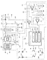
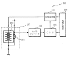
つぎに、図28〜図30にしたがってΔV検出方式の充電器300を説明する。携帯型の充電器300は本体300a、家庭用のACコンセントに差し込むACプラグ301、充電中に点灯するLED311およびバッテリーに接続されるDCプラグ307を有する。本体300a内には電源回路330、スイッチング回路340および制御回路350が設けられている。電源回路330にはACコンセントの商用電圧から2次電圧を出力するトランス402、トランス402から出力される交流を直流に変換するダイオードブリッジ403aを備えた平滑化回路403、VCC=5Vの電源電圧を供給する3端子レギュレータ409および充電電流を供給する定電流回路404が設けれている。この定電流回路404は4Vから8Vのバッテリー電圧範囲において800mAの電流を供給する。スイッチング回路340には充電電流をスイッチングするトランジスタ405、バッテリーからの逆流を防止するダイオード406、トランジスタ405をドライブするトランジスタ408が設けられている。制御回路350はワンチップマイコン410を中心にアンプ414、リセットIC413、LED411、トランジスタ412などから構成されており、ワンチップマイコン410はマイクロプロセッサの他に、周知のROM、RAM、タイマー、割り込みコントローラ、ADコンバータ、I/Oポート等を内蔵する。アンプ414はバッテリー電圧をレベル変換してワンチップマイコン410に内蔵されたADコンバータに出力する。トランジスタ412はLED411をドライブする。リセットIC413はハードウェアリセットに使用され、4.5Vを越えるとワンチップマイコン410のリセットを解除する。
【0005】
このような構成において、ACコンセントにACプラグ302が差し込まれるとトランス402に商用電圧が供給される。平滑化回路403はトランス402の二次電圧をダイオードブリッジ403aによって全波整流しコンデンサによって平滑化することで直流電圧に変換し、この直流電圧を定電流回路404および3端子レギュレータ409に供給する。3端子レギュレータ409から供給される電源電圧VCCが4.5Vを越えるとリセットIC413はハードウェアリセットを解除し、ワンチップマイコン410が動作状態になる。ワンチップマイコン410はトランジスタ408を駆動し、トランジスタ405をオンにする。ここで、バッテリーが接続されているとDCプラグ407の端子電圧はバッテリー電圧になるが、接続されていないときは解放電圧16Vになる。DCプラグ407にバッテリーが接続されているかどうかはアンプ414によってレベル変換された端子電圧をワンチップマイコン410がADコンバータを介して判断する。DCプラグ407にバッテリーが接続されていると解放電圧より低い端子電圧となるが、これは定電流回路404によってバッテリーに流れる電流が制限されるため端子電圧が下がるのである。ワンチップマイコン410はバッテリーの接続を確認すると、トランジスタ412をオンにしてLED411を点灯し充電中であることを表示する。ワンチップマイコン410はADコンバータに入力される端子電圧を一定の間隔でサンプリングして図30に示す満充電時の電圧変化−ΔVを検出する。満充電時の電圧変化−ΔVの検出はADコンバータからの刻々とサンプリングされる電圧の最大値を記憶しておき、この記憶された電圧からつぎにサンプリングされた電圧の差が100mVに達したことにより行なわれる。満充電時の電圧変化−ΔVが検出されるとワンチップマイコン410はトランジスタ408をオフし、充電を終了させると同時にトランジスタ412をオフしてLED411を消灯し使用者に充電の終了を知らせる。
【0006】
【発明が解決しようとする課題】
しかしながら、ΔT検出方式およびΔV検出方式のいずれの充電器においても以下に示すように充電不良になってしまうことがあった。ΔT検出方式の充電器では、サーミスタ104より検出される電池パック107内の電池温度が充電器が置かれた周囲温度より極めて低い状態で充電される場合、例えば0℃の屋外で使用した電池パックをほぼその0℃の状態のまま20℃の屋内に置かれた充電器にセットして充電を開始するときなどである。このとき、電池パック107内の電池103は、充電時に発生する熱によって起こる温度上昇に充電器の周囲から流れ込む熱によって起こる温度上昇が加わって温度上昇することになる。サーミスタ104で検出される温度上昇率が1℃/分を越えると満充電と判断するが、このように周囲の温度の影響も加わっているので、温度上昇率が1℃/分に至ったときを満充電と判断して充電を終了すると充電不足となってしまう問題があった。また、温度上昇率を1℃/分より高い値に設定しておくと電池の温度が周囲の温度とあまり変わらないときに今度は過充電となってしまうことが考えられた。
【0007】
同様に、ΔV検出方式の充電器では、満充電時の電圧変化−ΔVを検出する際に、DCプラグ407にバッテリーがうまく接続されておらず接触不良があると図31に示すように接点の断続的な接触によって急激な電圧変動がくりかえされることがある。そのようなときにその電圧変動を満充電時の電圧変化−ΔVであると判断して充電を終了してしまうことがあった。その結果、使用者が知らないままに充電不良が起きていた。
【0008】
そこで、これらの問題を解決するために、本発明は充電不良を防止できる充電器および充電方法を提供することを目的とする。
【0009】
【課題を解決するための手段】
上記目的を達成するために、第1の発明の充電器は、端子に接続された電池を充電する充電手段と、前記端子の電圧を測定する端子電圧測定手段と、この端子電圧測定手段によって測定される前記電圧の所定の電圧降下を検出する電圧降下検出手段と、この電圧降下検出手段によって検出される前記電圧の前記所定の電圧降下に応じて前記充電を終了する充電制御手段とを備えた充電器であって、前記充電手段による前記電池の充電中に前記端子電圧測定手段により測定される前記電圧の変動のくりかえしを検出する連続変動検出手段と、この連続変動検出手段によって前記電圧の変動のくりかえしが検出されたときに前記充電の異常を示す報知手段とを備える。
【0010】
さらに、第2の発明の充電器は、端子に接続された電池を充電する充電手段と、前記端子の電圧を測定する端子電圧測定手段と、この端子電圧測定手段によって測定される前記電圧の所定の電圧降下を検出する電圧降下検出手段と、この電圧降下検出手段によって検出される前記電圧の前記所定の電圧降下に応じて前記充電を終了する充電制御手段とを備えた充電器であって、前記充電手段による前記電池の充電中に前記端子電圧測定手段により測定される前記電圧の変動のくりかえしを検出する連続変動検出手段と、この連続変動検出手段によって前記電圧の変動のくりかえしが検出される検出回数を計数する連続変動計数手段と、この連続変動計数手段によって計数される前記検出回数が所定回数に達しないときは前記充電制御手段によって終了した充電を再開する再充電手段とを備える。
【0011】
また、第3の発明は、前記再充電手段によって充電が再開されたことを示す報知手段を備える。
【0012】
また、第4の発明は、端子に接続された電池を充電する充電工程と、前記端子の電圧を測定する電圧測定工程と、該測定される前記電圧の所定の電圧降下を検出する工程と、該検出される前記電圧の前記所定の電圧降下に応じて前記充電を終了する工程とを有する充電方法であって、前記充電工程による前記電池の充電中に前記電圧測定工程により測定される前記電圧の変動のくりかえしを検出する変動検出工程と、前記変動検出工程によって前記電圧の変動のくりかえしが検出されたときに前記充電の異常を示す工程とを備えたことを特徴とする。
【0013】
さらに、第5の発明の充電方法は、端子に接続された電池を充電する充電工程と、前記端子の電圧を測定する電圧測定工程と、該測定される前記電圧の所定の電圧降下を検出する電圧降下検出工程と、該電圧降下検出工程によって検出される前記電圧の前記所定の電圧降下に応じて前記充電を終了する工程とを有する充電方法であって、前記充電工程による前記電池の充電中に前記電圧測定工程により測定される前記電圧の変動のくりかえしを検出する変動検出工程と、該変動検出工程によって前記電圧の変動のくりかえしが検出される検出回数を計数する計数工程と、該計数工程によって計数される前記検出回数が所定回数に達しないときは終了した充電を再開する工程とを有することを特徴とする。
【0015】
【発明の実施の形態】
[第1実施形態]
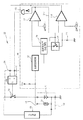
本発明の実施形態を図面に基づき説明する。図1は第1実施形態の充電器10の電気的構成を示すブロック図である。充電器10は充電回路16、制御回路25および充電オンオフ回路29を備え、端子14に電池パック13が接続される。電池パック13にはいわゆるニッカド電池11およびサーミスタ12が組み込まれており、サーミスタ12は電池11の表面温度を検出する。
【0016】
制御回路25はサーミスタ12の端子電圧を温度データに変換する温度変換回路15、単位時間当りの温度の変化を示す温度変化率を検出する温度変化率検出回路26の他に、コンパレータ27、28、アナログスイッチ21を備える。コンパレータ27は温度変化率検出回路26からの温度変化率を基準電圧1と比較し、電池の温度変化率が基準電圧1を下回ったかどうかを判別する。基準電圧1は電池温度と周囲温度の開きが小さくなって電池温度が十分に周囲になじんだときの電池の温度変化率に相当する電圧(本実施形態では0.5℃/minの温度変化率に相当する電圧)に予め設定されている。
【0017】
コンパレータ28はコンパレータ27と同様に温度変化率検出回路26からの温度変化率を基準電圧2と比較し、満充電時の温度変化率であるか否かを判別する。基準電圧2は満充電時の温度変化率に相当する電圧(本実施形態では1℃/minの温度変化率に相当する電圧)に予め設定されている。コンパレータ28の+入力端子には抵抗器22が接続されており、アナログスイッチ21がオフのときに+入力端子をプルブウンする。また、コンパレータ27の出力とコンパレータ28の反転出力を入力とするアンドゲート23が設けられており、これを論理積演算しその出力をRSフリップフロップ31のS端子に入力することでRSフリップフロップ31のS端子およびR端子が同時にHレベルになるのを防いでいる。
【0018】
温度変換回路15はアンプおよびボルテージフォロワからなり、サーミスタ電圧Vthを次段の温度変化率検出回路26に適した電圧に調整する。
【0019】
温度変化率検出回路26は図2に示すように遅延回路41、OPアンプ56および各抵抗器R1、R2、Rf1、Rf2を備える。遅延回路41は温度変換回路15によって増幅されたサーミスタ電圧を一定時間遅らせて出力する。OPアンプ56は抵抗器R1、R2、Rf1、Rf2とともに差動増幅器を形成する。抵抗器R1に流れる電流I1、抵抗器Rf1に流れる電流If1、抵抗器R2に流れる電流I2、抵抗器Rf2に流れる電流If2、OPアンプ56の+入力端子にかかる電圧Vp、OPアンプ56の−入力端子にかかる電圧Vn、OPアンプ56の出力電圧Vo、サーミスタ電圧Vth、遅延回路41を介したサーミスタ電圧Vth1と符号付けすると、OPアンプ56の出力電圧Voはつぎの関係式(1a〜4a)から
Vo=Vp−If1・Rf1 ……(1a)
Vp=Rf2×Vth/(R2+Rf2) ……(2a)
If1=I1=(Vth1−Vp)/R1 ……(3a)
R1=R2 ……(4a)
R1=Rf1 ……(5a)
次式(10A)のように表される。
【0020】
Vo=Vth−Vth1 ……(10a)
したがって、OPアンプ56はサーミスタ電圧Vthと遅延回路41で遅延されたサーミスタ電圧Vth1の変化分を出力する。これにより遅延回路41で設定された遅延時間を単位とするサーミスタ電圧の変化率、即ち電池11の温度変化率を検出することができる。遅延回路41はCCDを遅延素子として構成することができる。
【0021】
充電オンオフ回路29はRSフリップフロップ31およびアナログスイッチ32を有する。RSフリップフロップ31のS端子にHレベル信号を入力するとQ端子の出力がHレベルになってアナログスイッチ32がオンとなり、R端子にHレベル信号を入力するとQ端子の出力がLレベルになってアナログスイッチ32がオフとなる。充電回路16は定電流回路を中心に構成され、充電オンオフ回路29のアナログスイッチ32によってオンオフされる。
【0022】
上記の構成を有する充電器10の充電制御について説明する。充電器10の端子14に接続された電池パック13の電池温度が周囲温度に較べて低いときは電池温度は徐々に上昇していき高いときは徐々に下降していき、やがて電池温度は周囲温度になじんでいく。電池温度が周囲温度になじんでいないときは温度変化率検出回路26から出力される温度変化率は基準電圧1に較べて大きな値となるので、コンパレータ27の出力はLレベルになる。このとき、アンドゲート23の出力もLレベルになり、そのままRSフリップフロップ31のS端子はLレベルになる。したがって、アナログスイッチ32はオフであり、充電回路16はオンにならず電池パック13は充電されない。このとき、コンパレータ28の+入力端子がLレベルなのでRSフリップフロップ31のR端子はLレベルのままでQ端子の出力に影響を与えない。
【0023】
つぎに、時間が経過して電池温度が周囲温度になじんでくると温度変化率は徐々に小さな値となる。温度変化率がコンパレータ27の基準電圧1以下になるとコンパレータ27の出力はHレベルとなってRSフリップフロップ31のQ端子がHレベルにセットされるので、これによりアナログスイッチ32がオンになり充電回路16をオンして電池11に充電が開始される。また、温度変化率検出回路26はコンパレータ27の出力を信号ライン27aを介してフィードバックしており、コンパレータ27の−入力端子にその後もLレベルを出力し続け、コンパレータ27の出力をHレベルに保持する。このとき、アナログスイッチ21はオンとなり、コンパレータ28による温度変化率の検出が開始される。満充電時までは、基準電圧2の方が電池11の温度変化率より大きいのでコンパレータ28からLレベルが出力されて充電は継続する。
【0024】
電池温度が満充電の状態に近づくにつれて温度変化率は大きくなり、ついに基準電圧2を越えるとコンパレータ28の出力はHレベルになってRSフリップフロップ31をリセットする。これによりアナログスイッチ32はオフとなり充電回路16による充電は終了する。
【0025】
以上示したように、電池パック13を端子14に接続した後に電池温度が周囲温度になじんだことをその電池温度曲線の傾きである温度変化率から判断し十分なじんだことを確認してから充電を開始するので、周囲温度と電池温度の開きが大きいことによる電池温度の急な温度変化率を排除でき、満充電に至らないで充電を終了するといった充電不足を解消できる。
【0026】
[第2実施形態]
つぎに、第2実施形態について説明する。図3は第2実施形態の充電器70の構成を示すブロック図である。第2実施形態の充電器70は前記第1実施形態の充電器10における制御回路25およびRSフリップフロップ31を除いて代わりにマイクロプロセッサユニット(MPU)74を設けて構成される。このマイクロプロセッサユニット74は周知のCPU74d、ROM74e、RAM74fの他に、バッファレジスタ74c、入出力(I/O)ポート74a、A/Dコンバータ74bおよびタイマ74gを備えたワンチップマイコンである。MPU74には充電オンオフ回路79のアナログスイッチ79aがI/Oポート74aを介して接続されている。また、MPU74には基準電圧発生回路81、82および電池パック83のサーミスタ85がA/Dコンバータ74bを介して接続されている。基準電圧発生回路81、82にはそれぞれ基準値を設定するための分割抵抗器81a、81b、82a、82bが接続されており、それぞれ基準電圧1、基準電圧2を発生する。基準電圧1、基準電圧2は前記第1実施形態と同じ値に設定されている。
【0027】
MPU74はサーミスタ85と抵抗器84とで設定されるサーミスタ電圧Vthを前述のA/Dコンバータ74bを介して読取り、読み取ったデータから単位時間当たりの温度変化、つまり温度変化率を計算し、その計算された温度変化率が基準電圧発生回路81で発生する基準電圧1より小さくなるまで、つまり、温度変化率が十分に小さくなるまでは充電を開始せず、小さくなってからI/Oポート74aを介して充電オンオフ回路79にHレベルの制御信号を出力する。アナログスイッチ79aはオンになり充電回路80は充電を開始する。充電開始後は温度変化率が基準電圧発生回路82で発生される基準電圧2より大きくなるまで充電を続け、大きくなったらLレベルの制御信号を充電オンオフ回路79に出力して充電を終了する。
【0028】
図4および図5はMPU74が実行する充電制御ルーチンを示すフローチャートである。MPU74は起動するとくりかえし本ルーチンを実行する。始めに、電池パック83がセットされているかどうかを判断し(ステップS110)、セットされていなければ本ルーチンを一旦終了する。セットされているときにはサーミスタ電圧Vthの判定ステップS115を実行する。まず、サーミスタ電圧Vthを読み取り、バッファレジスタ74c内のTiレジスタにその値を記憶する(ステップS120)。つぎに、タイマ74gをスタートし(ステップS130)、10秒経過するのを待つ(ステップS140)。10秒経過後に再び、サーミスタ電圧Vthを読み取り、その値をバッファレジスタ74c内のT1レジスタに記憶する(ステップS150)。Tiレジスタの値からT1レジスタの値を差し引き、そのサーミスタ電圧Vthの変化分ΔVthをT0レジスタに記憶すると(ステップS160)、さらにT1レジスタの値をTiレジスタに移してつぎのサーミスタ電圧Vthの読み込みに備える。サーミスタ電圧Vthの変化分ΔVthが基準電圧1に較べて小さいかどうか判断し(ステップS180)、基準電圧1に較べて大きいときにはまだ電池温度と周囲温度に開きがあるとして充電をスタートさせることなく、一旦、タイマ74gをリセットして再びステップS130からの処理をくりかえす(ステップS190)。
【0029】
前述のステップS180で、変化分ΔVthが基準電圧1に較べて大きいと判断されたときは充電オンオフ回路79にHレベルの制御信号を出力して充電をスタートさせる(ステップS200)。充電が開始されたら、前述のサーミスタ電圧Vthの判定ステップS115と同様の判定ステップ215を実行する。即ち、サーミスタ電圧Vthを読み取りその値をTiレジスタに記憶すると、タイマ74gをスタートさせて10秒経過するのを待ち、10秒経過したら再びサーミスタ電圧Vthを読み込んでその変化分ΔVthをT0レジスタに記憶する。T1レジスタの値をTiレジスタに移してつぎのサーミスタ電圧Vthの読み込みに備える(ステップS210〜S260)。T0レジスタに記憶されているサーミスタ電圧Vthの変化分ΔVthが基準電圧2以上になっているかどうか判断し(ステップS270)、基準電圧2に達していないときは満充電に至っていないと判断してタイマ74gをリセットし(ステップS280)、再びステップS220からの処理をくりかえす。変化分ΔVthが基準電圧2より以上になっているときには満充電に至ったとして充電を終了し(ステップS290)、本ルーチンを一旦終了する。このように、マイクロコンピュータベースの第2実施形態の充電器70の場合も前記第1実施形態と同様の効果を有する。また、温度変化率に使用する単位時間の設定もプログラムにより簡単に変更することができる。
【0030】
[第3実施形態]
つぎに、図6に示す第3実施形態の充電器110について説明する。本実施形態の充電器110は前記第1実施形態の制御回路25および充電オンオフ回路29を変更して構成される。即ち、第3実施形態の制御回路125は前記第1実施形態と同様の温度変換回路115、温度変化率検出回路116およびコンパレータ118の他に、電池有無判別回路123、タイマ124a、124b、A/Dコンバータ125、補正時間設定回路126、基準電圧セレクト回路127、基準電圧発生器128および充電オンオフ制御回路133を有する。電池有無判別回路123は電池パック113がセットされたか否かを判断する。タイマ124aは電池パック113が端子に接続されてから設定時間(本実施形態では1分)が経過したときにA/Dコンバータ125にイネーブル信号を出力する。A/Dコンバータ125はイネーブル信号を受けた時点で温度変化率検出回路116からの温度変化率をディジタル値に変換する。補正時間設定回路126はディジタル値に変換された温度変化率に応じて補正時間を設定する。タイマ124bは設定された補正時間が経過したときに基準電圧セレクト回路127にセレクト信号を出力する。基準電圧セレクト回路127はA/Dコンバータ125でディジタル値に変換された温度変化率に応じて基準電圧発生器128の基準電圧を選択する。基準電圧発生器128は直列に接続された抵抗器128〜132の両端に加えられた電圧から分圧された電圧を基準電圧として発生する。補正時間および基準電圧の補正値はつぎの第8実施形態と同じく図8に示す値が用いられる。また、充電オンオフ回路119はアナログスイッチ119aだけから構成され、充電オンオフ制御回路133の制御信号にしたがって充電回路116をオンオフする。
【0031】
上記の構成を有する充電器110では、電池有無判別回路123は端子123aの電圧から電池パック113が接続されたかどうかを検出する。電池パック113が接続されたことを検出すると、タイマ124aの計測を開始させる。タイマ124aの設定時間(1分)が経過すると、タイマ124aはA/Dコンバータ125にイネーブル信号を出力し、同時に充電オンオフ制御回路133に制御信号を出力して充電を開始する。A/Dコンバータ125はこのイネーブル信号によってディジタル値に変換された温度変化率のデータを補正時間設定回路126および基準電圧セレクト回路127に出力する。補正時間設定回路126は温度変化率のデータにしたがって図8の補正時間を設定する。補正時間が設定されるとタイマ124bが計測を開始する。また、基準電圧セレクト回路127は温度変化率のデータにしたがって基準電圧発生回路128に選択信号を出力し、図8の補正値が付加された基準電圧を基準電圧発生回路128から選択する。例えば、抵抗器129の端子電圧Vaを補正された基準電圧とするとき、基準電圧セレクト回路127は端子電圧Vaの信号ライン135をコンパレータ118の−入力端子118aに接続する。タイマ124bが補正時間設定回路126によって設定された補正時間を計測し終わると基準電圧セレクト回路127に信号を出力する。基準電圧セレクト回路127は補正された基準電圧Vaから補正なしの基準電圧Vbの選択に切り替える。即ち、補正時間経過後は通常の基準電圧Vbをもとにコンパレータ118は充電を制御する。以上示したように、電池パック113接続後の電池の温度変化率から電池温度が周囲温度になじむまでの補正時間を予測して基準電圧を補正するので、電池温度が周囲温度になじむまで待つことなく充電を即座に開始できる。したがって、本実施形態の充電器は急速充電に適する。
【0032】
[第4実施形態]
つぎに、図7に示す第4実施形態の充電器150について説明する。この充電器150は前記第2実施形態と同様にマイクロコンピュータベースのものである。前記第2実施形態の基準電圧発生器81および基準電圧発生器82の代わりに、電池パック153が端子153aに接続されているか否かを検出する電池有無検出回路152および補正データメモリ158がMPU154に接続されている。タイマ154g、154hは2個設けられており、タイマ154gはサーミスタ電圧Vthの変化分の検出するときの単位時間として使用され、タイマ154hは充電時間の測定に使用される。その他の電気的構成については第2実施形態と同様である。補正データメモリ158には温度変化率つまり、サーミスタの電圧変化に対する基準電圧の補正値および補正時間がテーブルで格納されており、図8に示すように、このテーブルは電池パック153が接続された後の所定時間(1分)経過後の電池温度の変化を示すサーミスタ電圧の変化(V)、そのサーミスタ電圧の変化が周囲温度に対してなじむまでの補正時間(min)および補正値(V)が示されている。
【0033】
以上示した構成を有する充電器150では、電池パック153が接続されるとMPU154は電池温度に対応したサーミスタ電圧VthをA/Dコンバータ154bを介して読み取り、さらに電池パック153が充電器150に端子153aに接続されてからの所定時間(1分)後のサーミスタ電圧をA/Dコンバータ154bを介して読み取って、この間のサーミスタ電圧Vthの変化を演算する。演算されたサーミスタ電圧Vthの変化分△Vthを基に補正データメモリ158のテーブルを参照して補正時間および補正値をデータバス154kを介して読み込む。補正時間に達するまでは補正値を加えた基準電圧にしたがって温度変化率の検出を行なう。補正時間に達してからは補正値を加えない基準電圧にしたがって温度変化率の検出を行ない充電を制御する。これらの動作を図9および図10に示す充電制御フローチャートにしたがって説明する。
【0034】
本ルーチンはくりかえし実行される。電池パック153が端子に接続されてセットされたかどうかを判断し、セットされていないときには本ルーチンを一旦終了する(ステップS410)。セットされているときにはサーミスタ電圧Vthを読み取り、バッファレジスタ154cのTiレジスタにサーミスタ電圧Vthを記憶する(ステップS420)。同時にタイマ154gをスタートし(ステップS430)、タイマ154gの設定時間(1分)が経過したら再度サーミスタ電圧Vthを読み取り、その読み取った値をバッファレジスタ154cのT1レジスタに記憶する。Tiレジスタの値からT1レジスタの値を引いた値を同じくバッファレジスタ154cのToレジスタに記憶する(ステップS460)。MPU154は補正データメモリ158のテーブルを参照して(ステップS470)Toレジスタの値から補正時間tおよび基準電圧の補正値を決定する(ステップS480、ステップS490)。決定された補正時間tおよび補正値はRAM154fに記憶される。この後、MPU154は充電オンオフ回路159のアナログスイッチ159aをオンにして充電を開始し(ステップS510)、同時に充電用のタイマ154hの計測をスタートする(ステップS520)。サーミスタ電圧Vthを読み取り、バッファレジスタ154cのTiレジスタにサーミスタ電圧Vthを記憶する(ステップS530)。同時にタイマ154gをスタートし(ステップS540)、タイマ154gの設定時間(10秒)が経過したら(ステップS550)再びサーミスタ電圧Vthを読み取り、その値をT1レジスタに記憶する(ステップS560)。Tiレジスタの値からT1レジスタの値を引いた値をToレジスタに記憶し(ステップS570)、T1レジスタの値をTiレジスタに移す(ステップS580)。
【0035】
つぎに、タイマ154hの充電時間が補正時間tに達したかどうかを判断する(ステップS590)。補正時間tに達しているときには、Toレジスタに記憶されたサーミスタ電圧Vthの変化分△Vth、即ち温度変化率が基準電圧以上になっているかどうかを判断し(ステップS600)、基準電圧に至っていないときにはタイマ154gをリセットして(ステップS610)再び、ステップS540からのサーミスタ電圧Vthの変化分△Vthの測定をくりかえす。ステップS600でサーミスタ電圧Vthの変化分が基準電圧を越えているときには満充電に至ったとして充電を終了する(ステップS630)。一方、ステップS590で充電時間が補正時間tに達していないときには、Toレジスタに記憶されたサーミスタ電圧Vthの変化分△Vthが補正値を加えた基準電圧以上になっているかどうかを判断する(ステップS620)。補正した基準電圧(基準電圧に補正値を加えた値)以上になっていれば充電を終了する(ステップS630)が、基準電圧に達していないときにはタイマ154gをリセットし、再びステップS540からのサーミスタ電圧Vthの変化分△Vthの測定をくりかえす。
【0036】
以上示したように、本実施形態の充電器150は前記第3実施形態と同様の効果が得ることができ、急速充電に適する。
【0037】
前記第1実施形態〜第4実施形態の充電器においては、電池の温度および温度変化率からだけで充電制御を行っているので、充電器などにサーミスタを設けなくても済ますことができる。
【0038】
[第5実施形態]
図11は第5実施形態の充電器180の電気的構成を示すブロック図である。この充電器180はCPU181、定電圧電源182、定電流回路183、A/Dコンバータ186およびサーミスタ187を備える。さらに、この第5実施形態の充電器180は前記第1〜第4実施形態までの充電器と異なりサーミスタ187を充電器180の内側に設け、充電器の温度(Tc)を測定するようにされている。充電器180の端子180a、180bに着脱自在に接続される電池パック190はニッケル水素電池194とサーミスタ195を組み合わせたものである。ニッケル水素電池194は公称電圧1.2V、公称容量1100mAhの電池を5本直列に接続したものであり、サーミスタ195はニッケル水素電池194の電池温度(Tb)を測定する。
【0039】
A/Dコンバータ186は一定のサンプリング速度でサーミスタ187、195の信号をディジタル値に変換する。CPU181はA/Dコンバータ186で変換されたデータをもとに演算を行なって定電流回路183を駆動する。また、定電圧電源182は安定化電源回路で、AC100VからCPU181が動作するのに必要なDC5Vと定電流回路183を動作させるのに必要なDC10Vを出力する。
【0040】
図12はニッケル水素電池194を充電したときの充電曲線(a)および電池表面温度曲線(b)、(c)を示すグラフである。曲線(b)は電池パック190を次式(10A)の条件で充電したときの電池表面温度曲線であり、曲線(c)は電池パック190を次式(10B)の条件で充電を開始したときの電池表面温度曲線である。
【0041】
電池温度(Tb)−充電器温度(Tc)≧ −5℃ ……(10A)
電池温度(Tb)−充電器温度(Tc)< −5℃ ……(10B)
電池パック190は曲線(a)に示すように電池電圧の最大(d)を満充電時としてそれ以降の電圧は徐々に小さくなる特性を示す。電池表面温度曲線の領域(f)では式(10A)の下で電池の自己発熱により約0.3℃/分の温度上昇率を示す。同じく式(10A)の下での領域(e)では満充電(d)以降の温度上昇率として1℃/分を示す。また、式(10B)の下での領域(h)では電池の自己発熱と周囲温度の温度上昇が加算されて約1.2℃/分の温度上昇率を示す。同じく式(10B)の下での領域(g)では満充電以降の温度上昇率として、電池の自己発熱と周囲温度による温度上昇が加算され1.5℃/分以上を示す。このように、式(10A)の下で充電したときは電池の温度上昇率1℃/分が満充電時を示し、式(10B)の下で充電したときは電池の温度上昇率1.5℃/分が満充電時を示す。
【0042】
つぎに、CPU181が実行する充電制御ルーチンについて説明する。図13は充電制御ルーチンを示すフローチャートである。本ルーチンを開始すると、CPU181はA/Dコンバータ186によってディジタル化されたデータを1秒間隔で5回サンプリングし、その最大値と最小値を切り捨て3回分のデータの平均をそれぞれとることによって電池温度(Tb)データと充電器温度(Tc)データを求める(ステップS610)。CPU181は定電流回路183に充電開始の指令を出力する(ステップS620)。充電開始の指令と同時に、CPU181は内蔵タイマをスタートさせて1分間計測する(ステップS630)。1分経過すると、再び前述した手順により電池温度(Tb)データを測定する(ステップS640)。単位時間を1分とする温度上昇率dT/dtを次式(20A)にしたがって算出する(ステップS650)。
【0043】
dT/dt=現在の電池温度(Tb)−1分前の電池温度(Tb)……(20A)
つぎに、充電前の電池温度(Tb)と充電器温度(Tc)の差を算出し、その差が(Tb−Tc)≧−5℃を満足するかどうかを判断する(ステップS660)。満足するなら電池温度が十分に充電器温度になじんでいるとして、さらに電池194の温度上昇率がdT/dt≧1℃を満足するかどうかを判断する(ステップS670)。満足しないのであれば未だ満充電に至っていないとしてステップS630からの処理をくりかえす。満足していれば満充電に至ったとして本ルーチンを一旦終了する(ステップS690)。また、ステップS660で(Tb−Tc)≧−5℃を満足しないときは充電器温度になじんでいないとして、さらに温度上昇率がdT/dt≧1.5℃を満足するかどうかを判断する(ステップS680)。満足しないのであれば未だ満充電に至っていないとしてステップS630からの処理をくりかえす。満足していれば満充電に至ったとして本ルーチンを一旦終了する(ステップS690)。
【0044】
尚、電池温度(Tb)と充電器温度(Tc)の温度差を−5℃を基準とする2段階よりもっと細かく段階設定してもよく、このとき、充電器温度にどの程度なじんでいるかによって満充電時の温度上昇率を細かく設定できる。
【0045】
また、電池温度(Tb)と充電器温度(Tc)の温度差を求める際にステップS610で電池温度(Tb)と充電器温度(Tc)のそれぞれの温度をA/Dコンバータ186でアナログディジタル変換して温度データを検出していたが、A/Dコンバータ186の前に差動増幅器を付加して電池温度(Tb)と充電器温度(Tc)の差分をA/Dコンバータ186に入力するようにしてもよい。このような構成にすると、充電開始前の電池温度(Tb)と充電器温度(Tc)の温度差は差動増幅器の出力をA/Dコンバータ186でアナログディジタル変換することによって得ることができ、得られた温度差から前述の式(10A)、(10B)にしたがって満充電時の温度上昇率を設定することができる。また、充電開始後でも充電器温度(Tc)はほとんど変化しないので、差動増幅器の出力をA/Dコンバータ186を介してCPU181が所定時間毎に取り込むと差動増幅器の出力の変化分は電池温度(Tb)の変化分を示すことになる。この電池温度(Tb)の変化分、即ち温度上昇率が満充電時の温度上昇率に達したときに充電を終了する。このように差動増幅器を設けることで、A/Dコンバータを1台で済ますことができる。また、CPU181によるA/Dコンバータのデータ取込みも半減することができ、処理の高速化に繋がる。
【0046】
[第6実施形態]
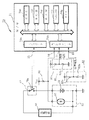
つぎに、第6実施形態として△V検出方式の充電器210について説明する。図14は充電器210の外観を示す斜視図である。携帯型の充電器210は本体210a、家庭用のACコンセントに差し込むACプラグ211、充電中に点灯するLED213、異常時に点灯するLED215およびバッテリーに接続されるDCプラグ207を有する。本体210a内には、図15に示すように電源回路240、スイッチング回路245および制御回路260が設けられている。電源回路240にはACコンセントの商用電圧から2次電圧を出力するトランス222、トランス222から出力される交流を直流に変換するダイオードブリッジ223aを備えた平滑化回路223、VCC=5Vの電源電圧を供給する3端子レギュレータ229および充電電流を供給する定電流回路224が設けれている。この定電流回路224は4Vから8Vのバッテリー電圧範囲において800mAの電流を供給する。スイッチング回路245には充電電流をスイッチングするトランジスタ225、バッテリーからの逆流を防止するダイオード226、トランジスタ225をドライブするトランジスタ228が設けられている。制御回路260はワンチップマイコン230を中心にアンプ234、リセットIC233、LED215、213、トランジスタ235、232などから構成されており、ワンチップマイコン230はマイクロプロセッサの他に、周知のROM、RAM、タイマー、割り込みコントローラ、ADコンバータ、I/Oポート等を内蔵する。
【0047】
アンプ234はバッテリー電圧をレベル変換してワンチップマイコン230に内蔵されたADコンバータに出力する。トランジスタ235、232はそれぞれLED215、213をドライブする。リセットIC233はハードウェアリセットに使用され、4.5Vを越えるとワンチップマイコン230のリセットを解除する。
【0048】
さらに、ワンチップマイコン230には異常検出回路250が接続されている。
【0049】
異常検出回路250はワンチップマイコン230のカウンタ230bに接続されたコンパレータ253、コンパレータ253の+入力端子に接続される抵抗分圧器255、−入力端子に微分回路256を介して接続される抵抗分圧器258およびDCプラグ207の端子電圧を反転して抵抗分圧器255、258に出力する反転増幅器257を備える。
【0050】
このような構成において、ACコンセントにACプラグ211が差し込まれるとトランス222に商用電圧が供給される。平滑化回路223はトランス222の二次電圧をダイオードブリッジ223aによって全波整流しコンデンサによって平滑化することで直流電圧に変換し、この直流電圧を定電流回路224および3端子レギュレータ229に供給する。3端子レギュレータ229から供給される電源電圧VCCが4.5Vを越えるとリセットIC233はハードウェアリセットを解除し、ワンチップマイコン230が動作状態になる。ワンチップマイコン230はトランジスタ228を駆動し、トランジスタ225をオンにする。ここで、バッテリーが接続されているとDCプラグ207の端子電圧はバッテリー電圧になるが、接続されていないときは解放電圧16Vになる。DCプラグ207にバッテリーが接続されているかどうかはアンプ234によってレベル変換された端子電圧をワンチップマイコン230がADコンバータ230aを介して判断する。DCプラグ207にバッテリーが接続されていると解放電圧より低い端子電圧となるが、これは定電流回路224によってバッテリーに流れる電流が制限されるため端子電圧が下がるのである。ワンチップマイコン230はバッテリーの接続を確認すると、トランジスタ232をオンにしてLED213を点灯し充電中であることを表示する。ワンチップマイコン230はADコンバータ230aに入力される端子電圧を一定の間隔でサンプリングして前述した図30に示す満充電時の電圧変化−ΔVを検出する。満充電時の電圧変化−ΔVの検出はADコンバータ230aからの刻々とサンプリングされる電圧の最大値を記憶しておき、この記憶された電圧からつぎにサンプリングされた電圧の差が100mVに達したことにより行なわれる。満充電時の電圧変化−ΔVが検出されるとワンチップマイコン230はトランジスタ225をオフし、充電を終了させると同時にトランジスタ232をオフしてLED213を消灯し使用者に充電の終了を知らせる。
【0051】
また、コンパレータ253の出力端子はワンチップマイコン230の割込み端子に接続されており、コンパレータ253の出力は+、−の入力端子にかかる電圧レベルで決定される。すなわち、DCプラグ207に急激な電圧変動がなければDCプラグ207の端子電圧は反転増幅器257で反転して抵抗分圧器255、258に与えられる。抵抗分圧器255、258では抵抗分圧器255で出力される電圧の方が抵抗分圧器258で微分回路256を介して出力される電圧よりも大きな値となっているので、コンパレータ253からHレベルの出力信号がワンチップマイコン230に入力される。ところが、DCプラグ207に接触不良が起きて端子電圧に急激な変動が発生すると分圧抵抗器258に接続されている微分回路256はこの電圧変動を増幅することになり、この変動する微分回路256の電圧と抵抗分圧器255の電圧を比較してコンパレータ253はHレベルとLレベルを交互に出力することになる。このとき、ワンチップマイコン230はコンパレータ253の出力信号の立ち下がりによって割込み処理を実行し、カウンタ230bのエラーカウント値をインクリメントする。カウンタ230bの値が一定値に達してオーバフローするとトランジスタ235を駆動してLED215を点灯し異常を表示する。LED215が点灯した状態でワンチップマイコン230は−△Vを検出しても充電中に異常があったとして充電を終了せずに充電を再開する。このとき、ワンチップマイコン230に内蔵されたタイマ230cによってLED213を0.5秒ごとに点滅させて再充電であることを知らせる。使用者はLED215の点灯によって異常のあったことを知り、LED213の点滅によって再充電であることを知ることができる。
【0052】
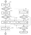
つぎに、ワンチップマイコン230によって実行される充電制御ついて説明する。図16は充電制御ルーチンを示すフローチャートである。ワンチップマイコン230は本ルーチンをくりかえし実行し、始めにソフトウェアによるイニシャル処理を行ない、カウンタ230bをクリア、タイマ230cをリセット、LED213、215を消灯するなどの初期化を行なう(ステップS710)。 つぎに、トランジスタ228を駆動してトランジスタ225がオンとなり定電流回路224によって充電電流の供給を開始する(ステップS720)。バッテリがDCプラグ207に接続されるのを待ち(ステップS730)、バッテリがDCプラグ207に接続されるとLED213を点灯する(ステップS740)。ワンチップマイコン230はA/Dコンバータ230aを介してDCプラグ207の端子電圧をサンプリングにより入力する(ステップS750)。サンプリングされたDCプラグ207の端子電圧が前回までに記憶されている最大値に較べて大きいときには今回サンプリングされた端子電圧を最大値として更新する(ステップS760)。また、記憶されている最大値に対してサンプリングされたDCプラグ207の端子電圧が100mVを下回るまで下がっているかどうかを判断する(ステップS770)。100mVを下回るまで下がっていないときは1秒間待った後に(ステップS780)、ステップS750に戻って再びサンプリングをサンプリングをくりかえす。ステップS770で100mVを下回るまでに下がっていると判断されたときは一旦、トランジスタ225をオフして充電電流の供給を停止する(ステップS790)。カウンタ230bのエラーカウント値が一定値を越えてオバーフローし異常が起こったかどうかを判断する(ステップS810)。エラーカウント値が一定値以下で異常のなかったときは満充電に至ったとしてLED213を消灯し(ステップS870)、バッテリが外されるのを待って本ルーチンを終了する(ステップS890)。一方、ステップS810でエラーカウント値が一定値を越えてオーバフローしているときはLED215を点灯して異常の起きたことを指示し(ステップS830)、さらにその異常が連続して起きたかどうかを判断する(ステップS840)。連続して異常が続いたのであればそれ以上の充電を中止するために前述と同様にLED213を消灯し(ステップS870)、バッテリが外されるのを待つ(ステップS890)。ステップS840で始めて起きたのだと判断されると、トランジスタ225を駆動して充電電流の供給を再開する(ステップS850)。このとき、タイマ割込みを0.5秒毎に行ってLED213を交互にON/OFFし、点滅表示によって再充電中であることを指示する(ステップS860)。図18はLED213、215の表示の態様を示している。この後、再びステップS750に戻ってDCプラグ207の端子電圧のサンプリングをくりかえす。
【0053】
図17はカウンタ230bのエラーカウント値が一定値を越えてオーバーフローしたときに、ワンチップマイコン230が実行する割込み処理ルーチンのフローチャートである。前述したように、DCプラグ207に接触不良などが起きて端子電圧に急激な変動が発生すると分圧抵抗器258に接続されている微分回路256はこの電圧変動を増幅することになり、この変動する微分回路256の電圧と抵抗分圧器253の電圧を比較してコンパレータ253はHレベルとLレベルを交互に出力する。ワンチップマイコン230はこの立ち下がり信号によって割込み処理を行い、カウンタ230bのエラーカウント値がオーバーフローしていない間はインクリメントする(ステップS920、S925)が、オバーフローするとそれ以後なにもせず割込み処理ルーチンを終了する。
【0054】
以上示したように、本実施形態によればDCプラグ207の端子とバッテリの間に接触不良が起きて充電不足のまま充電が終了しても、その充電中に異常のあったことをLED215によって表示するので充電不足であることを使用者は容易に知ることができ、バッテリにDCプラグを差し直すなどの処置によって充電不良を回避できる。また、一過性の充電電圧の変動に対しては即座に異常と判断して充電を中断しないので、しかも連続して異常と判断されない限り中断した充電を再開させるので、充電不良の発生を極めて抑えることができる。
【0055】
[第7実施形態]
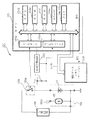
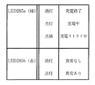
本実施形態の充電器280は前記第6実施形態の充電器210の表示制御の部分を違えるだけで構成されるので、以下に相違する部分の構成を説明する。図19は充電器280の外観を示す斜視図である。図において、特に説明を要しない部分は、前記第6実施形態と同じ符号で示す。この充電器280には前記第6実施形態のLED213、215の代わりに緑色、赤色のLED285a、285bが一体に成形された2色発光ダイオードが設けられている。LEDを駆動する回路は前記第6実施形態と同じであり、LED213、215をそれぞれ緑色、赤色のLED285a、285bにするだけでよい。ワンチップマイコンが実行する充電制御ルーチンは、前記第6実施形態のステップS790〜ステップS890部分を変更するもので、図20に示すようにステップS830の代わりにステップS887に変更し、ステップS870とステップS890の間にステップS875およびステップS885を追加して構成される。即ち、カウンタでエラーカウント値がオーバーフローしていて異常があったときはLEDを点灯させる代わりにワンチップマイコンのRAMに異常状態であることをフラグのセットにより記憶しておく(ステップS915)。始めての異常であればLED285aを点滅させて(ステップS888)充電を再開するが、異常が連続しているときには緑色のLED285aを消灯する(ステップS873)。この後、途中で異常があったかどうかをRAMに記憶されているフラグの状態から判断し(ステップS875)、異常がなければバッテリが外されるのを待つ。異常があったときには赤色のLED285bを点灯してから同様に待つ(ステップS885)。したがって、緑色、赤色のLED285a、285bの表示態様は図21に示すように示される。
【0056】
[第8実施形態]
本実施形態の充電器290も前記第6実施形態の充電器210の表示制御の部分を違えるだけで構成されるので、以下に相違する部分の構成を説明する。図22は充電器290の外観を示す斜視図である。図において、特に説明を要しない部分は、前記第6実施形態と同じ符号で示す。この充電器290は前記第6実施形態のLEDを液晶表示(LCD)モジュール294に変更して構成される。図23に示すように、前記第6実施形態のLED213、215の駆動回路の代わりにLCDモジュール294がワンチップマイコン295に接続されており、このLCDモジュール294はワンチップマイコン295に内蔵されたLCDドライバによって駆動される。その他の電気的構成は前記第6実施形態と同様である。
【0057】
ワンチップマイコン295が実行する充電制御ルーチンは前記第6実施形態の表示制御に係る部分を変更して構成され、ここではその変更部分についてだけ説明する。図24および図25に示すように、ワンチップマイコン295はイニシャル処理においてLCDモジュール294に「READY」のメッセージを表示する(ステップS901)。バッテリがDCプラグに接続されると「ジュウデン」を表示する(ステップS904)。前記第7実施形態と同様に充電中に異常があったときは異常状態をワンチップマイコンのRAMにフラグをセットすることで記憶し(ステップS915)、始めての異常であればLCDモジュール940に「リトライ」と表示して(ステップS918)充電を再開する。連続して異常が起きたときは「エラー」を表示し(ステップS919)、1度異常があった後に再充電により満充電に至ったときは「リトライOK」と表示して(ステップS920)バッテリが外されるのを待って本ルーチンを終了する。また、全く異常なく満充電に至ったときには「シュウリョウ」と表示して(ステップS911)本ルーチンを終了する。
【0058】
[第9実施形態]
本実施形態の充電器も前記第6実施形態の充電器210にタイマ機能を付加して構成されるが、タイマは前記第6実施形態で示したワンチップマイコン230に内蔵されたタイマ230cを用いているので電気的構成を特に変更させなくても実現できる。定電流回路は150mAの充電電流を供給する。本実施形態の充電制御ルーチンを図26に示すフローチャートにしたがって説明するが、本ルーチンは第6実施形態のステップS750〜ステップS780をステップS955およびステップS956に置き換えることで構成される。図において、特に説明を要しない部分は、前記第6実施形態と同じ符号で示す。即ち、ワンチップマイコンはバッテリがDCプラグに接続されて充電を開始し、LEDの点灯と同時にタイマをスタートさせる(ステップS955)。タイマが8時間経過するまで充電を続ける(ステップS956)。8時間経過したら充電を停止し、前記第6実施形態と同様にカウンタのエラーカウント値がオバーフローしているかどうかを判断してその後の充電制御を行なう。
【0059】
尚、上記実施形態は本発明の範囲を逸脱しない限りにおいて、種々の変更が可能である。例えば、サーミスタを内蔵した電池パックに限らず、サーミスタの内蔵していない電池であってもよく、電池を充電器にセットするとサーミスタが電池表面に接触して電池の温度を測定できるようにされたものでもよい。また、温度を検出する素子として、金属酸化物からなるサーミスタ以外にバイメタル式の温度センサ等を使用することができる。また、サーミスタは正特性(PTC)、負特性(NTC)のいずれも用いることができる。
【0060】
【発明の効果】
本発明によれば、端子電圧の変動のくりかえしが検出されるときは充電の異常を報知手段により示すので、使用者は充電の異常を容易に知ることができる。したがって、使用者は電池を端子に接続し直して再充電を図ってもよい。電圧の変動のくりかえしを検出する検出回数が所定回数を越えないときは一旦、終了した充電を再開するので、一過性の電圧変動による充電終了を排除することができる。また、報知手段により再充電が示されるので、使用者は再充電であることを容易に知ることができる。
【図面の簡単な説明】
【図1】第1実施形態の充電器10の電気的構成を示すブロック図である。
【図2】温度変化率検出回路26の構成を示す回路図である。
【図3】第2実施形態の充電器70の電気的構成を示すブロック図である。
【図4】MPU74が実行する充電制御ルーチンを示すフローチャートである。
【図5】図4に続く充電制御ルーチンを示すフローチャートである。
【図6】第3実施形態の充電器110の電気的構成を示すブロック図である。
【図7】第4実施形態の充電器150の電気的構成を示すブロック図である。
【図8】サーミスタ電圧変化に対応する補正時間および補正値を示す説明図である。
【図9】MPU154が実行する充電制御ルーチンを示すフローチャートである。
【図10】図9に続く充電制御ルーチンを示すフローチャートである。
【図11】第5実施形態の充電器180の電気的構成を示すブロック図である。
【図12】充電時間に対する電池電圧および電池温度の特性を示す説明図である。
【図13】CPU181が実行する充電制御ルーチンを示すフローチャートである。
【図14】第6実施形態の充電器210の外観を示す斜視図である。
【図15】充電器210の電気的構成を示す回路図である。
【図16】ワンチップマイコン230が実行する充電制御ルーチンを示すフローチャートである。
【図17】ワンチップマイコン230が実行する割り込み処理ルーチンを示すフローチャートである。
【図18】LED213、215の表示態様を示す説明図である。
【図19】第7実施形態の充電器280の外観を示す斜視図である。
【図20】充電器280によって実行される充電制御ルーチンの一部を示すフローチャートである。
【図21】LED285a、285bの表示態様を示す説明図である。
【図22】第8実施形態の充電器290の外観を示す斜視図である。
【図23】充電器290の電気的構成の一部を示すブロック図である。
【図24】ワンチップマイコン295が実行する充電制御ルーチンを示すフローチャートである。
【図25】図24に続く充電制御ルーチンを示すフローチャートである。
【図26】第9実施形態の充電器が実行する充電制御ルーチンを示すフローチャートである。
【図27】従来の充電器の電気的構成を示すブロック図である。
【図28】従来の充電器300の外観を示す斜視図である。
【図29】充電器300の電気的構成を示す回路図である。
【図30】充電時間に対する電池電圧を示す特性図である。
【図31】充電時間に対する端子電圧を示す特性図である。
【符号の説明】
10… 充電器
11… 電池
13… 電池パック
14… サーミスタ
26… 温度変化率検出回路
27、28… コンパレータ
29… 充電オンオフ回路
[0001]
TECHNICAL FIELD OF THE INVENTION
The present invention relates to a charger for controlling charging of a secondary battery and a charging method.
[0002]
[Prior art]
Conventionally, as a charger for controlling the charging of a secondary battery such as a nickel-cadmium battery or a nickel-metal hydride battery, a so-called ΔT detection method that detects the completion of charging from a temperature rise rate of the battery at full charge, and a battery at full charge There is known a so-called ΔV detection system which detects the completion of charging from the voltage drop of the voltage.
[0003]
For example, as shown in FIG. 27, the charger 100 of the ΔT detection system has a constant voltage power supply 106, a constant current circuit 101, a CPU 105, and an A / D converter 102, and a constant voltage from the constant current circuit 101 to a connected battery pack 107. Supply charging current. The battery pack 107 is integrated by combining several batteries 103 and a thermistor 104, and the temperature of the battery 103 is detected by the thermistor 104 attached to the exterior surface of the battery 103. The detected battery temperature is converted by the A / D converter 102 into data that can be handled by the CPU 105. When the battery temperature indicates a temperature increase rate of 1 ° C./min or more, the CPU 105 determines that the battery is fully charged and stops supplying the charging current.
[0004]
Next, the charger 300 of the ΔV detection method will be described with reference to FIGS. The portable charger 300 has a main body 300a, an AC plug 301 inserted into a household AC outlet, an LED 311 that lights up during charging, and a DC plug 307 connected to a battery. A power supply circuit 330, a switching circuit 340, and a control circuit 350 are provided in the main body 300a. The power supply circuit 330 includes a transformer 402 that outputs a secondary voltage from a commercial voltage of an AC outlet, a smoothing circuit 403 that includes a diode bridge 403a that converts AC output from the transformer 402 into DC, and a power supply voltage of VCC = 5V. A three-terminal regulator 409 for supplying and a constant current circuit 404 for supplying a charging current are provided. The constant current circuit 404 supplies a current of 800 mA in a battery voltage range of 4 V to 8 V. The switching circuit 340 includes a transistor 405 for switching a charging current, a diode 406 for preventing backflow from a battery, and a transistor 408 for driving the transistor 405. The control circuit 350 is composed of an amplifier 414, a reset IC 413, an LED 411, a transistor 412, and the like centering on a one-chip microcomputer 410. The one-chip microcomputer 410 has a well-known ROM, RAM, timer, interrupt controller, Built-in AD converter, I / O port, etc. The amplifier 414 converts the level of the battery voltage and outputs it to an AD converter built in the one-chip microcomputer 410. Transistor 412 drives LED 411. The reset IC 413 is used for hardware reset, and when the voltage exceeds 4.5 V, the reset of the one-chip microcomputer 410 is released.
[0005]
In such a configuration, when the AC plug 302 is inserted into the AC outlet, commercial voltage is supplied to the transformer 402. The smoothing circuit 403 converts the secondary voltage of the transformer 402 to a DC voltage by full-wave rectification by a diode bridge 403a and smoothing by a capacitor, and supplies this DC voltage to the constant current circuit 404 and the three-terminal regulator 409. When the power supply voltage VCC supplied from the three-terminal regulator 409 exceeds 4.5 V, the reset IC 413 cancels the hardware reset, and the one-chip microcomputer 410 enters an operating state. The one-chip microcomputer 410 drives the transistor 408 and turns on the transistor 405. Here, when a battery is connected, the terminal voltage of the DC plug 407 becomes the battery voltage, but when the battery is not connected, the terminal voltage becomes 16V. Whether the battery is connected to the DC plug 407 or not is determined by the one-chip microcomputer 410 via the AD converter based on the terminal voltage whose level has been converted by the amplifier 414. When a battery is connected to the DC plug 407, the terminal voltage becomes lower than the release voltage. This is because the current flowing to the battery is limited by the constant current circuit 404, so that the terminal voltage decreases. When confirming the connection of the battery, the one-chip microcomputer 410 turns on the transistor 412 to turn on the LED 411 to indicate that the battery is being charged. The one-chip microcomputer 410 samples the terminal voltage input to the AD converter at regular intervals, and detects a voltage change -ΔV at the time of full charge shown in FIG. For the detection of the voltage change during full charge-ΔV, the maximum value of the voltage sampled from the AD converter is stored every time, and the difference between the stored voltage and the next sampled voltage reaches 100 mV. It is performed by When the voltage change -.DELTA.V at the time of full charge is detected, the one-chip microcomputer 410 turns off the transistor 408 and ends the charge, and at the same time, turns off the transistor 412 and turns off the LED 411 to notify the user of the end of the charge.
[0006]
[Problems to be solved by the invention]
However, in any of the chargers of the ΔT detection method and the ΔV detection method, charging failure may occur as described below. In the case of the ΔT detection type charger, when the battery temperature in the battery pack 107 detected by the thermistor 104 is extremely low than the ambient temperature where the charger is placed, for example, the battery pack used outdoors at 0 ° C. Is set at about 0 ° C. in a charger placed indoors at 20 ° C. to start charging. At this time, the temperature of the battery 103 in the battery pack 107 rises due to the temperature rise caused by the heat generated during charging and the temperature rise caused by the heat flowing from around the charger. When the temperature rise rate detected by the thermistor 104 exceeds 1 ° C./min, it is determined that the battery is fully charged. However, when the temperature rise rate reaches 1 ° C./min. There is a problem that when the battery is judged to be fully charged and the charging is terminated, the battery becomes insufficiently charged. Also, if the temperature rise rate is set to a value higher than 1 ° C./min, it was considered that the battery would be overcharged when the temperature of the battery was not so different from the ambient temperature.
[0007]
Similarly, in the battery charger of the ΔV detection method, when detecting the voltage change −ΔV at the time of full charge, if the battery is not properly connected to the DC plug 407 and there is a contact failure, as shown in FIG. Sudden voltage fluctuations may be repeated due to intermittent contact. In such a case, the voltage change may be determined to be the voltage change at full charge minus ΔV, and charging may be terminated. As a result, charging failure occurred without the user's knowledge.
[0008]
Then, in order to solve these problems, an object of the present invention is to provide a charger and a charging method that can prevent poor charging.
[0009]
[Means for Solving the Problems]
In order to achieve the above object, a battery charger according to a first aspect of the present invention includes a charging unit for charging a battery connected to a terminal, a terminal voltage measuring unit for measuring a voltage of the terminal, and a terminal voltage measuring unit. Of the voltage Predetermined voltage drop The voltage to detect Descent Detection means and this voltage Descent Of the voltage detected by the detecting means. The predetermined voltage drop A charging control means for terminating the charging according to Measured by the terminal voltage measuring means during charging of the battery by the charging means A continuous fluctuation detecting means for detecting the repetition of the voltage fluctuation, and a notifying means for indicating the abnormality of the charging when the repetition of the voltage fluctuation is detected by the continuous fluctuation detecting means.
[0010]
Further, the battery charger of the second invention is a charging means for charging a battery connected to a terminal, a terminal voltage measuring means for measuring a voltage of the terminal, and a terminal voltage measuring means for measuring the voltage of the terminal. Predetermined voltage drop The voltage to detect Descent Detection means and this voltage Descent Of the voltage detected by the detecting means. The predetermined voltage drop A charging control means for terminating the charging according to Measured by the terminal voltage measuring means during charging of the battery by the charging means A continuous fluctuation detecting means for detecting the repetition of the voltage fluctuation; a continuous fluctuation counting means for counting the number of times the repetition of the voltage fluctuation is detected by the continuous fluctuation detecting means; Recharging means for resuming the charging terminated by the charging control means when the number of times of detection does not reach a predetermined number.
[0011]
Further, the third invention includes a notifying means indicating that charging has been restarted by the recharging means.
[0012]
According to a fourth aspect, a battery connected to a terminal is charged. charging Measuring the voltage of the terminal Voltage measurement And measuring the voltage Predetermined voltage drop And detecting the voltage of the detected voltage. The predetermined voltage drop Terminating the charging in accordance with Measured by the voltage measuring step during charging of the battery by the charging step Detecting repeated voltage fluctuations Fluctuation detection Process and By the fluctuation detecting step Indicating a charge abnormality when repeated voltage fluctuations are detected.
[0013]
Further, in the charging method according to the fifth aspect, the battery connected to the terminal is charged. charging Measuring the voltage of the terminal Voltage measurement And measuring the voltage Predetermined voltage drop Detect Voltage drop detection Process and By the voltage drop detecting step Of the detected voltage The predetermined voltage drop Terminating the charging in accordance with Measured by the voltage measuring step during charging of the battery by the charging step Detecting repeated voltage fluctuations Fluctuation detection Process and By the fluctuation detecting step Count the number of times the voltage fluctuation is detected repeatedly Counting The process, By counting process Restarting the completed charging when the counted number of times of detection does not reach a predetermined number of times.
[0015]
BEST MODE FOR CARRYING OUT THE INVENTION
[First Embodiment]
An embodiment of the present invention will be described with reference to the drawings. FIG. 1 is a block diagram illustrating an electrical configuration of the charger 10 according to the first embodiment. The charger 10 includes a charging circuit 16, a control circuit 25, and a charging on / off circuit 29. The terminal 14 is connected to the battery pack 13. A so-called NiCd battery 11 and a thermistor 12 are incorporated in the battery pack 13, and the thermistor 12 detects the surface temperature of the battery 11.
[0016]
The control circuit 25 includes a temperature conversion circuit 15 for converting the terminal voltage of the thermistor 12 into temperature data, a temperature change rate detection circuit 26 for detecting a temperature change rate indicating a change in temperature per unit time, comparators 27 and 28, An analog switch 21 is provided. The comparator 27 compares the temperature change rate from the temperature change rate detection circuit 26 with the reference voltage 1 to determine whether or not the battery temperature change rate is lower than the reference voltage 1. The reference voltage 1 is a voltage (corresponding to a temperature change rate of 0.5 ° C./min in the present embodiment) corresponding to the temperature change rate of the battery when the difference between the battery temperature and the ambient temperature is small and the battery temperature is sufficiently adapted to the surroundings. Is set in advance.
[0017]
Like the comparator 27, the comparator 28 compares the temperature change rate from the temperature change rate detection circuit 26 with the reference voltage 2 and determines whether or not the temperature change rate at the time of full charge. The reference voltage 2 is set in advance to a voltage corresponding to a temperature change rate at the time of full charge (a voltage corresponding to a temperature change rate of 1 ° C./min in the present embodiment). The resistor 22 is connected to the + input terminal of the comparator 28, and pulls down the + input terminal when the analog switch 21 is off. Further, an AND gate 23 is provided which receives the output of the comparator 27 and the inverted output of the comparator 28 as inputs. The AND gate 23 performs a logical product operation and inputs the output to the S terminal of the RS flip-flop 31 so that the RS flip-flop 31 Of the S terminal and the R terminal at the same time are prevented from becoming H level.
[0018]
The temperature conversion circuit 15 includes an amplifier and a voltage follower, and adjusts the thermistor voltage Vth to a voltage suitable for the temperature change rate detection circuit 26 at the next stage.
[0019]
The temperature change rate detection circuit 26 includes a delay circuit 41, an OP amplifier 56, and resistors R1, R2, Rf1, Rf2 as shown in FIG. The delay circuit 41 outputs the thermistor voltage amplified by the temperature conversion circuit 15 with a delay for a predetermined time. The OP amplifier 56 forms a differential amplifier with the resistors R1, R2, Rf1, and Rf2. The current I1 flowing through the resistor R1, the current If1 flowing through the resistor Rf1, the current I2 flowing through the resistor R2, the current If2 flowing through the resistor Rf2, the voltage Vp applied to the + input terminal of the OP amplifier 56, and the − input of the OP amplifier 56 When the voltage Vn applied to the terminal, the output voltage Vo of the OP amplifier 56, the thermistor voltage Vth, and the thermistor voltage Vth1 via the delay circuit 41 are denoted by symbols, the output voltage Vo of the OP amplifier 56 is obtained from the following relational expressions (1a to 4a).
Vo = Vp−If1 · Rf1 (1a)
Vp = Rf2 × Vth / (R2 + Rf2) (2a)
If1 = I1 = (Vth1-Vp) / R1 (3a)
R1 = R2 (4a)
R1 = Rf1 (5a)
It is expressed as the following equation (10A).
[0020]
Vo = Vth-Vth1 (10a)
Accordingly, the OP amplifier 56 outputs a change of the thermistor voltage Vth and the thermistor voltage Vth1 delayed by the delay circuit 41. As a result, the rate of change of the thermistor voltage in units of the delay time set by the delay circuit 41, that is, the rate of temperature change of the battery 11, can be detected. The delay circuit 41 can use a CCD as a delay element.
[0021]
The charge on / off circuit 29 has an RS flip-flop 31 and an analog switch 32. When an H level signal is input to the S terminal of the RS flip-flop 31, the output of the Q terminal becomes H level and the analog switch 32 is turned on. When an H level signal is input to the R terminal, the output of the Q terminal becomes L level. The analog switch 32 is turned off. The charging circuit 16 is mainly composed of a constant current circuit, and is turned on and off by an analog switch 32 of a charging on / off circuit 29.
[0022]
The charging control of the charger 10 having the above configuration will be described. When the battery temperature of the battery pack 13 connected to the terminal 14 of the charger 10 is lower than the ambient temperature, the battery temperature rises gradually, and when it is higher, it gradually falls. Get used to it. When the battery temperature is not adjusted to the ambient temperature, the temperature change rate output from the temperature change rate detection circuit 26 is larger than the reference voltage 1, so that the output of the comparator 27 is at the L level. At this time, the output of the AND gate 23 also becomes L level, and the S terminal of the RS flip-flop 31 becomes L level as it is. Therefore, the analog switch 32 is off, the charging circuit 16 is not turned on, and the battery pack 13 is not charged. At this time, since the + input terminal of the comparator 28 is at the L level, the R terminal of the RS flip-flop 31 remains at the L level and does not affect the output of the Q terminal.
[0023]
Next, as time passes, the battery temperature gradually adapts to the ambient temperature, and the temperature change rate gradually becomes smaller. When the temperature change rate becomes equal to or lower than the reference voltage 1 of the comparator 27, the output of the comparator 27 goes to H level, and the Q terminal of the RS flip-flop 31 is set to H level. 16 is turned on to start charging the battery 11. Further, the temperature change rate detecting circuit 26 feeds back the output of the comparator 27 via the signal line 27a, and keeps outputting the L level to the-input terminal of the comparator 27 thereafter, and keeps the output of the comparator 27 at the H level. I do. At this time, the analog switch 21 is turned on, and the comparator 28 starts detecting the temperature change rate. Until the full charge, the reference voltage 2 is higher than the temperature change rate of the battery 11, so that the comparator 28 outputs the L level and the charge continues.
[0024]
As the battery temperature approaches a fully charged state, the rate of temperature change increases. When the battery temperature finally exceeds the reference voltage 2, the output of the comparator 28 goes high and the RS flip-flop 31 is reset. As a result, the analog switch 32 is turned off, and the charging by the charging circuit 16 ends.
[0025]
As described above, after the battery pack 13 is connected to the terminal 14, it is determined from the temperature change rate, which is the slope of the battery temperature curve, that the battery temperature has adjusted to the ambient temperature. Is started, a rapid temperature change rate of the battery temperature due to a large difference between the ambient temperature and the battery temperature can be eliminated, and insufficient charging such as ending the charging without reaching the full charge can be solved.
[0026]
[Second embodiment]
Next, a second embodiment will be described. FIG. 3 is a block diagram showing the configuration of the charger 70 of the second embodiment. The charger 70 of the second embodiment is configured by providing a microprocessor unit (MPU) 74 instead of the control circuit 25 and the RS flip-flop 31 in the charger 10 of the first embodiment. The microprocessor unit 74 is a one-chip microcomputer provided with a buffer register 74c, an input / output (I / O) port 74a, an A / D converter 74b, and a timer 74g, in addition to the well-known CPU 74d, ROM 74e, and RAM 74f. An analog switch 79a of a charge on / off circuit 79 is connected to the MPU 74 via an I / O port 74a. The MPU 74 is connected to reference voltage generation circuits 81 and 82 and a thermistor 85 of the battery pack 83 via an A / D converter 74b. Divided resistors 81a, 81b, 82a and 82b for setting reference values are connected to the reference voltage generating circuits 81 and 82, respectively, and generate reference voltages 1 and 2 respectively. The reference voltage 1 and the reference voltage 2 are set to the same values as in the first embodiment.
[0027]
The MPU 74 reads the thermistor voltage Vth set by the thermistor 85 and the resistor 84 via the above-described A / D converter 74b, calculates a temperature change per unit time from the read data, that is, a temperature change rate, and calculates the calculation. The charging is not started until the temperature change rate becomes smaller than the reference voltage 1 generated by the reference voltage generation circuit 81, that is, until the temperature change rate becomes sufficiently small. An H-level control signal is output to the charge on / off circuit 79 via the control circuit. The analog switch 79a is turned on, and the charging circuit 80 starts charging. After the start of the charging, the charging is continued until the temperature change rate becomes higher than the reference voltage 2 generated by the reference voltage generating circuit 82, and when it becomes higher, an L level control signal is outputted to the charging on / off circuit 79 to terminate the charging.
[0028]
4 and 5 are flowcharts showing a charge control routine executed by the MPU 74. When activated, the MPU 74 repeats this routine. First, it is determined whether or not the battery pack 83 has been set (step S110), and if not, this routine is once ended. When it is set, the determination step S115 of the thermistor voltage Vth is executed. First, the thermistor voltage Vth is read, and its value is stored in the Ti register in the buffer register 74c (step S120). Next, the timer 74g is started (step S130), and waits for 10 seconds to elapse (step S140). After a lapse of 10 seconds, the thermistor voltage Vth is read again, and the value is stored in the T1 register in the buffer register 74c (step S150). When the value of the T1 register is subtracted from the value of the Ti register, and the change ΔVth of the thermistor voltage Vth is stored in the T0 register (step S160), the value of the T1 register is further transferred to the Ti register to read the next thermistor voltage Vth. Prepare. It is determined whether or not the change ΔVth of the thermistor voltage Vth is smaller than the reference voltage 1 (step S180). If the change ΔVth is larger than the reference voltage 1, it is determined that the battery temperature and the ambient temperature are still open, and charging is not started. The timer 74g is reset once, and the process from step S130 is repeated again (step S190).
[0029]
If it is determined in step S180 that the change ΔVth is greater than the reference voltage 1, an H-level control signal is output to the charge on / off circuit 79 to start charging (step S200). When charging is started, a determination step 215 similar to the above-described determination step S115 of the thermistor voltage Vth is executed. That is, when the thermistor voltage Vth is read and the value is stored in the Ti register, the timer 74g is started and waits for 10 seconds to elapse. After 10 seconds elapses, the thermistor voltage Vth is read again and the change ΔVth is stored in the T0 register. I do. The value of the T1 register is transferred to the Ti register to prepare for reading the next thermistor voltage Vth (steps S210 to S260). It is determined whether the variation ΔVth of the thermistor voltage Vth stored in the T0 register is equal to or higher than the reference voltage 2 (step S270). 74g is reset (step S280), and the processing from step S220 is repeated. When the variation ΔVth is equal to or higher than the reference voltage 2, it is determined that the battery has been fully charged, charging is terminated (step S 290), and the present routine is terminated once. As described above, the charger 70 of the second embodiment based on the microcomputer has the same effects as those of the first embodiment. Also, the setting of the unit time used for the temperature change rate can be easily changed by the program.
[0030]
[Third embodiment]
Next, the charger 110 of the third embodiment shown in FIG. 6 will be described. The charger 110 of the present embodiment is configured by changing the control circuit 25 and the charging on / off circuit 29 of the first embodiment. That is, the control circuit 125 of the third embodiment includes a battery presence / absence determination circuit 123, timers 124a and 124b, A / A, in addition to the temperature conversion circuit 115, the temperature change rate detection circuit 116, and the comparator 118 similar to the first embodiment. It has a D converter 125, a correction time setting circuit 126, a reference voltage selection circuit 127, a reference voltage generator 128, and a charge on / off control circuit 133. The battery presence / absence determination circuit 123 determines whether or not the battery pack 113 has been set. The timer 124a outputs an enable signal to the A / D converter 125 when a set time (one minute in this embodiment) has elapsed since the battery pack 113 was connected to the terminal. Upon receiving the enable signal, the A / D converter 125 converts the temperature change rate from the temperature change rate detection circuit 116 into a digital value. The correction time setting circuit 126 sets a correction time according to the temperature change rate converted into a digital value. The timer 124b outputs a select signal to the reference voltage select circuit 127 when the set correction time has elapsed. The reference voltage selection circuit 127 selects a reference voltage of the reference voltage generator 128 according to the temperature change rate converted into a digital value by the A / D converter 125. The reference voltage generator 128 generates, as a reference voltage, a voltage obtained by dividing the voltage applied to both ends of the resistors 128 to 132 connected in series. The values shown in FIG. 8 are used for the correction time and the correction value of the reference voltage as in the following eighth embodiment. Further, the charging on / off circuit 119 includes only an analog switch 119a, and turns on / off the charging circuit 116 according to a control signal of the charging on / off control circuit 133.
[0031]
In the charger 110 having the above configuration, the battery presence / absence determination circuit 123 detects whether or not the battery pack 113 is connected from the voltage of the terminal 123a. Upon detecting that the battery pack 113 has been connected, the timer 124a starts counting. When the set time (1 minute) of the timer 124a elapses, the timer 124a outputs an enable signal to the A / D converter 125, and simultaneously outputs a control signal to the charge on / off control circuit 133 to start charging. The A / D converter 125 outputs the temperature change rate data converted into a digital value by the enable signal to the correction time setting circuit 126 and the reference voltage selection circuit 127. The correction time setting circuit 126 sets the correction time of FIG. 8 according to the data of the temperature change rate. When the correction time is set, the timer 124b starts measuring. Further, the reference voltage selection circuit 127 outputs a selection signal to the reference voltage generation circuit 128 according to the data of the temperature change rate, and selects the reference voltage to which the correction value of FIG. For example, when the terminal voltage Va of the resistor 129 is used as the corrected reference voltage, the reference voltage selection circuit 127 connects the signal line 135 of the terminal voltage Va to the negative input terminal 118a of the comparator 118. When the timer 124b finishes measuring the correction time set by the correction time setting circuit 126, it outputs a signal to the reference voltage selection circuit 127. The reference voltage selection circuit 127 switches from the corrected reference voltage Va to the selection of the reference voltage Vb without correction. That is, after the correction time has elapsed, the comparator 118 controls charging based on the normal reference voltage Vb. As described above, the reference voltage is corrected by predicting the correction time until the battery temperature adapts to the ambient temperature from the temperature change rate of the battery after the battery pack 113 is connected, and therefore, it is necessary to wait until the battery temperature adapts to the ambient temperature. Charging can be started immediately. Therefore, the charger of the present embodiment is suitable for quick charging.
[0032]
[Fourth embodiment]
Next, a charger 150 according to the fourth embodiment shown in FIG. 7 will be described. This charger 150 is microcomputer-based, as in the second embodiment. Instead of the reference voltage generator 81 and the reference voltage generator 82 of the second embodiment, the MPU 154 includes a battery presence / absence detection circuit 152 for detecting whether the battery pack 153 is connected to the terminal 153a and a correction data memory 158. It is connected. Two timers 154g and 154h are provided. The timer 154g is used as a unit time for detecting a change in the thermistor voltage Vth, and the timer 154h is used for measuring a charging time. Other electrical configurations are the same as in the second embodiment. The correction data memory 158 stores a temperature change rate, that is, a correction value and a correction time of the reference voltage with respect to a voltage change of the thermistor in a table, and this table is stored after the battery pack 153 is connected as shown in FIG. The change (V) of the thermistor voltage indicating the change in the battery temperature after the elapse of the predetermined time (1 minute), the correction time (min) and the correction value (V) until the change of the thermistor voltage adapts to the ambient temperature It is shown.
[0033]
In the charger 150 having the above-described configuration, when the battery pack 153 is connected, the MPU 154 reads the thermistor voltage Vth corresponding to the battery temperature via the A / D converter 154b. The A / D converter 154b reads the thermistor voltage after a predetermined time (1 minute) from being connected to the 153a, and calculates a change in the thermistor voltage Vth during this time. The correction time and the correction value are read via the data bus 154k with reference to the table of the correction data memory 158 based on the calculated change ΔVth of the thermistor voltage Vth. Until the correction time is reached, the temperature change rate is detected according to the reference voltage to which the correction value has been added. After reaching the correction time, the temperature change rate is detected in accordance with the reference voltage to which no correction value is applied, and charging is controlled. These operations will be described with reference to the charging control flowcharts shown in FIGS.
[0034]
This routine is executed repeatedly. It is determined whether or not the battery pack 153 is connected to the terminal and set. If the battery pack 153 has not been set, the routine ends once (step S410). If it is set, the thermistor voltage Vth is read, and the thermistor voltage Vth is stored in the Ti register of the buffer register 154c (step S420). At the same time, the timer 154g is started (step S430). When the set time (1 minute) of the timer 154g has elapsed, the thermistor voltage Vth is read again, and the read value is stored in the T1 register of the buffer register 154c. The value obtained by subtracting the value of the T1 register from the value of the Ti register is stored in the To register of the buffer register 154c (step S460). The MPU 154 determines the correction time t and the correction value of the reference voltage from the value of the To register with reference to the table of the correction data memory 158 (Step S470) (Steps S480 and S490). The determined correction time t and correction value are stored in the RAM 154f. Thereafter, the MPU 154 turns on the analog switch 159a of the charge on / off circuit 159 to start charging (step S510), and at the same time, starts counting by the charging timer 154h (step S520). The thermistor voltage Vth is read, and the thermistor voltage Vth is stored in the Ti register of the buffer register 154c (step S530). At the same time, the timer 154g is started (step S540), and after the set time (10 seconds) of the timer 154g has elapsed (step S550), the thermistor voltage Vth is read again and the value is stored in the T1 register (step S560). The value obtained by subtracting the value of the T1 register from the value of the Ti register is stored in the To register (step S570), and the value of the T1 register is transferred to the Ti register (step S580).
[0035]
Next, it is determined whether the charging time of the timer 154h has reached the correction time t (step S590). If the correction time t has been reached, it is determined whether or not the change ΔVth of the thermistor voltage Vth stored in the To register, that is, whether the temperature change rate is equal to or higher than the reference voltage (step S600). Sometimes, the timer 154g is reset (step S610), and the measurement of the change ΔVth of the thermistor voltage Vth from step S540 is repeated again. When the variation of the thermistor voltage Vth exceeds the reference voltage in step S600, it is determined that the battery is fully charged, and the charging is terminated (step S630). On the other hand, if the charging time has not reached the correction time t in step S590, it is determined whether the change ΔVth of the thermistor voltage Vth stored in the To register is equal to or higher than the reference voltage to which the correction value has been added (step S590). S620). If the voltage is equal to or higher than the corrected reference voltage (the value obtained by adding the correction value to the reference voltage), the charging is terminated (step S630). If the voltage has not reached the reference voltage, the timer 154g is reset, and the thermistor from step S540 is returned again. The measurement of the change ΔVth of the voltage Vth is repeated.
[0036]
As described above, the charger 150 of the present embodiment can achieve the same effects as those of the third embodiment, and is suitable for quick charging.
[0037]
In the chargers of the first to fourth embodiments, the charge control is performed only based on the battery temperature and the temperature change rate, so that the thermistor does not need to be provided in the charger or the like.
[0038]
[Fifth Embodiment]
FIG. 11 is a block diagram illustrating an electrical configuration of the charger 180 according to the fifth embodiment. The charger 180 includes a CPU 181, a constant voltage power supply 182, a constant current circuit 183, an A / D converter 186, and a thermistor 187. Furthermore, the charger 180 of the fifth embodiment differs from the chargers of the first to fourth embodiments in that a thermistor 187 is provided inside the charger 180 to measure the temperature (Tc) of the charger. ing. Battery pack 190 detachably connected to terminals 180 a and 180 b of charger 180 is a combination of nickel-metal hydride battery 194 and thermistor 195. The nickel-metal hydride battery 194 is a battery in which five batteries having a nominal voltage of 1.2 V and a nominal capacity of 1100 mAh are connected in series, and the thermistor 195 measures the battery temperature (Tb) of the nickel-metal hydride battery 194.
[0039]
The A / D converter 186 converts the signals of the thermistors 187 and 195 into digital values at a constant sampling rate. The CPU 181 drives the constant current circuit 183 by performing calculations based on the data converted by the A / D converter 186. Further, the constant voltage power supply 182 is a stabilized power supply circuit, and outputs 5 V DC required for the operation of the CPU 181 and 10 V DC required for operating the constant current circuit 183 from 100 V AC.
[0040]
FIG. 12 is a graph showing the charging curve (a) and the battery surface temperature curves (b) and (c) when the nickel-metal hydride battery 194 is charged. A curve (b) is a battery surface temperature curve when the battery pack 190 is charged under the condition of the following equation (10A), and a curve (c) is when the battery pack 190 is started to be charged under the condition of the following equation (10B). 5 is a battery surface temperature curve of FIG.
[0041]
Battery temperature (Tb) −Charger temperature (Tc) ≧ −5 ° C. (10A)
Battery temperature (Tb) −Charger temperature (Tc) <− 5 ° C. (10B)
As shown by the curve (a), the battery pack 190 has a characteristic in which the maximum (d) of the battery voltage is set to the time of full charge, and the voltage thereafter becomes gradually smaller. In the area (f) of the battery surface temperature curve, a temperature rise rate of about 0.3 ° C./min is exhibited by the self-heating of the battery under the equation (10A). Similarly, in the area (e) under the equation (10A), the temperature rise rate after full charge (d) is 1 ° C./min. In the area (h) under the equation (10B), the self-heating of the battery and the temperature rise of the ambient temperature are added to show a temperature rise rate of about 1.2 ° C./min. Similarly, in the area (g) under the equation (10B), the self-heating of the battery and the temperature rise due to the ambient temperature are added as the temperature rise rate after full charge, and the rate is 1.5 ° C./min or more. Thus, when charged under the formula (10A), the battery temperature rise rate of 1 ° C./min indicates full charge, and when charged under the formula (10B), the battery temperature rise rate is 1.5. C / min indicates the time of full charge.
[0042]
Next, a charge control routine executed by the CPU 181 will be described. FIG. 13 is a flowchart showing a charge control routine. When this routine is started, the CPU 181 samples the data digitized by the A / D converter 186 five times at one second intervals, truncates the maximum value and the minimum value, and averages the data for three times to obtain the battery temperature. (Tb) data and charger temperature (Tc) data are obtained (step S610). The CPU 181 outputs a charge start command to the constant current circuit 183 (step S620). At the same time as the charging start command, the CPU 181 starts the built-in timer and measures for one minute (step S630). After one minute, the battery temperature (Tb) data is measured again according to the above-described procedure (step S640). The temperature rise rate dT / dt with a unit time of one minute is calculated according to the following equation (20A) (step S650).
[0043]
dT / dt = current battery temperature (Tb) —battery temperature one minute before (Tb) (20A)
Next, the difference between the battery temperature (Tb) before charging and the charger temperature (Tc) is calculated, and it is determined whether or not the difference satisfies (Tb−Tc) ≧ −5 ° C. (step S660). If so, it is determined that the battery temperature is sufficiently adjusted to the charger temperature, and it is determined whether the temperature rise rate of the battery 194 satisfies dT / dt ≧ 1 ° C. (step S670). If it is not satisfied, it is determined that the battery has not yet been fully charged, and the processing from step S630 is repeated. If it is satisfied, it is determined that the battery has been fully charged, and this routine is once ended (step S690). If (Tb−Tc) ≧ −5 ° C. is not satisfied in step S660, it is determined that the charger is not adapted to the charger temperature, and it is further determined whether or not the temperature rise rate satisfies dT / dt ≧ 1.5 ° C. Step S680). If it is not satisfied, it is determined that the battery has not yet been fully charged, and the processing from step S630 is repeated. If it is satisfied, it is determined that the battery has been fully charged, and this routine is once ended (step S690).
[0044]
Note that the temperature difference between the battery temperature (Tb) and the charger temperature (Tc) may be set in more detailed steps than two steps based on −5 ° C. At this time, depending on how much the battery temperature adapts to the charger temperature. The temperature rise rate at full charge can be set finely.
[0045]
Further, when calculating the temperature difference between the battery temperature (Tb) and the charger temperature (Tc), the A / D converter 186 converts the respective temperatures of the battery temperature (Tb) and the charger temperature (Tc) into analog / digital in step S610. However, a differential amplifier is added before the A / D converter 186 to input the difference between the battery temperature (Tb) and the charger temperature (Tc) to the A / D converter 186. It may be. With such a configuration, the temperature difference between the battery temperature (Tb) and the charger temperature (Tc) before the start of charging can be obtained by analog-to-digital conversion of the output of the differential amplifier by the A / D converter 186. From the obtained temperature difference, the temperature rise rate at the time of full charge can be set according to the above formulas (10A) and (10B). Also, since the charger temperature (Tc) hardly changes even after the start of charging, when the CPU 181 takes in the output of the differential amplifier at predetermined time intervals via the A / D converter 186, the change in the output of the differential amplifier is changed by the battery. This indicates a change in the temperature (Tb). The charging is terminated when the change in the battery temperature (Tb), that is, the temperature rise rate reaches the temperature rise rate at the time of full charge. By providing the differential amplifier in this way, one A / D converter can be used. In addition, the data capture of the A / D converter by the CPU 181 can be halved, which leads to an increase in processing speed.
[0046]
[Sixth embodiment]
Next, a description will be given of a の V detection type charger 210 as a sixth embodiment. FIG. 14 is a perspective view showing the appearance of the charger 210. The portable charger 210 has a main body 210a, an AC plug 211 that is inserted into a household AC outlet, an LED 213 that lights up during charging, an LED 215 that lights up when an abnormality occurs, and a DC plug 207 that is connected to a battery. As shown in FIG. 15, a power supply circuit 240, a switching circuit 245, and a control circuit 260 are provided in the main body 210a. The power supply circuit 240 includes a transformer 222 that outputs a secondary voltage from a commercial voltage of an AC outlet, a smoothing circuit 223 that includes a diode bridge 223a that converts AC output from the transformer 222 to DC, and a power supply voltage of VCC = 5V. A three-terminal regulator 229 for supplying and a constant current circuit 224 for supplying a charging current are provided. The constant current circuit 224 supplies a current of 800 mA in a battery voltage range of 4 V to 8 V. The switching circuit 245 includes a transistor 225 for switching a charging current, a diode 226 for preventing backflow from a battery, and a transistor 228 for driving the transistor 225. The control circuit 260 includes an amplifier 234, a reset IC 233, LEDs 215, 213, transistors 235, 232, and the like centering on a one-chip microcomputer 230. The one-chip microcomputer 230 includes a well-known ROM, RAM, and timer in addition to the microprocessor. , An interrupt controller, an AD converter, an I / O port, and the like.
[0047]
The amplifier 234 converts the level of the battery voltage and outputs it to an AD converter built in the one-chip microcomputer 230. Transistors 235 and 232 drive LEDs 215 and 213, respectively. The reset IC 233 is used for hardware reset, and when the voltage exceeds 4.5 V, the reset of the one-chip microcomputer 230 is released.
[0048]
Further, an abnormality detection circuit 250 is connected to the one-chip microcomputer 230.
[0049]
The abnormality detection circuit 250 includes a comparator 253 connected to the counter 230b of the one-chip microcomputer 230, a resistance voltage divider 255 connected to the + input terminal of the comparator 253, and a resistance voltage divider connected to the-input terminal via the differentiating circuit 256. 258 and an inverting amplifier 257 that inverts the terminal voltage of the DC plug 207 and outputs the inverted voltage to the resistive voltage dividers 255 and 258.
[0050]
In such a configuration, when the AC plug 211 is inserted into the AC outlet, commercial voltage is supplied to the transformer 222. The smoothing circuit 223 converts the secondary voltage of the transformer 222 to a DC voltage by full-wave rectification by a diode bridge 223a and smoothing by a capacitor, and supplies this DC voltage to the constant current circuit 224 and the three-terminal regulator 229. When the power supply voltage VCC supplied from the three-terminal regulator 229 exceeds 4.5 V, the reset IC 233 releases the hardware reset, and the one-chip microcomputer 230 enters an operation state. The one-chip microcomputer 230 drives the transistor 228 and turns on the transistor 225. Here, when the battery is connected, the terminal voltage of the DC plug 207 becomes the battery voltage, but when the battery is not connected, the release voltage becomes 16V. Whether the battery is connected to the DC plug 207 or not is determined by the one-chip microcomputer 230 via the AD converter 230a based on the terminal voltage whose level has been converted by the amplifier 234. When a battery is connected to the DC plug 207, the terminal voltage becomes lower than the release voltage. This is because the current flowing to the battery is limited by the constant current circuit 224, so that the terminal voltage decreases. When confirming the connection of the battery, the one-chip microcomputer 230 turns on the transistor 232 to turn on the LED 213 to indicate that the battery is being charged. The one-chip microcomputer 230 samples the terminal voltage input to the AD converter 230a at regular intervals to detect the above-described voltage change at full charge −ΔV shown in FIG. For the detection of the voltage change -ΔV at the time of full charge, the maximum value of the voltage sampled every moment from the AD converter 230a is stored, and the difference between the next sampled voltage from this stored voltage reaches 100 mV. It is done by doing. When the voltage change -.DELTA.V at the time of full charge is detected, the one-chip microcomputer 230 turns off the transistor 225 to terminate the charge, and at the same time, turns off the transistor 232 to turn off the LED 213 and notify the user of the end of the charge.
[0051]
The output terminal of the comparator 253 is connected to the interrupt terminal of the one-chip microcomputer 230, and the output of the comparator 253 is determined by the voltage level applied to the + and-input terminals. That is, if there is no abrupt voltage change in the DC plug 207, the terminal voltage of the DC plug 207 is inverted by the inverting amplifier 257 and supplied to the resistive voltage dividers 255 and 258. In the resistor dividers 255 and 258, the voltage output from the resistor divider 255 is higher than the voltage output from the resistor divider 258 via the differentiation circuit 256. The output signal is input to the one-chip microcomputer 230. However, when a contact failure occurs in the DC plug 207 and a sudden change occurs in the terminal voltage, the differentiating circuit 256 connected to the voltage-dividing resistor 258 amplifies this voltage change, and this fluctuating differential circuit 256 Is compared with the voltage of the resistive voltage divider 255, and the comparator 253 outputs the H level and the L level alternately. At this time, the one-chip microcomputer 230 executes an interrupt process at the falling edge of the output signal of the comparator 253, and increments the error count value of the counter 230b. When the value of the counter 230b reaches a certain value and overflows, the transistor 235 is driven to turn on the LED 215 and display an abnormality. Even when the one-chip microcomputer 230 detects -ΔV in a state where the LED 215 is turned on, it determines that there is an abnormality during charging and restarts charging without terminating the charging. At this time, the LED 213 is blinked every 0.5 seconds by the timer 230c built in the one-chip microcomputer 230 to indicate that it is recharging. The user can know that there is an abnormality by turning on the LED 215, and can know that it is recharging by blinking the LED 213.
[0052]
Next, charging control performed by the one-chip microcomputer 230 will be described. FIG. 16 is a flowchart showing a charge control routine. The one-chip microcomputer 230 repeatedly executes this routine, performs initial processing by software, and performs initialization such as clearing the counter 230b, resetting the timer 230c, and turning off the LEDs 213 and 215 (step S710). Next, the transistor 228 is driven to turn on the transistor 225, and the supply of the charging current is started by the constant current circuit 224 (step S720). It waits for the battery to be connected to the DC plug 207 (step S730), and turns on the LED 213 when the battery is connected to the DC plug 207 (step S740). The one-chip microcomputer 230 inputs the terminal voltage of the DC plug 207 through the A / D converter 230a by sampling (step S750). If the sampled terminal voltage of the DC plug 207 is higher than the previously stored maximum value, the terminal voltage sampled this time is updated as the maximum value (step S760). Further, it is determined whether or not the terminal voltage of the DC plug 207 sampled with respect to the stored maximum value has fallen below 100 mV (step S770). If the voltage has not dropped to below 100 mV, after waiting for 1 second (step S780), the process returns to step S750 to repeat sampling again. If it is determined in step S770 that the voltage has dropped below 100 mV, the transistor 225 is once turned off to stop supplying the charging current (step S790). It is determined whether the error count value of the counter 230b overflows beyond a certain value and an abnormality occurs (step S810). If the error count value is equal to or less than the predetermined value and there is no abnormality, the LED 213 is turned off assuming that the battery is fully charged (step S870), and the routine is terminated after the battery is removed (step S890). On the other hand, if the error count value exceeds a certain value and overflows in step S810, the LED 215 is turned on to indicate that an abnormality has occurred (step S830), and it is determined whether the abnormality has occurred continuously. (Step S840). If the abnormality continues, the LED 213 is turned off in the same manner as described above to stop further charging (step S870), and waits for the battery to be removed (step S890). If it is determined in step S840 that this has occurred for the first time, the transistor 225 is driven to restart the supply of the charging current (step S850). At this time, a timer interrupt is performed every 0.5 seconds, and the LED 213 is alternately turned ON / OFF, and a blinking display indicates that recharging is being performed (step S860). FIG. 18 shows a display mode of the LEDs 213 and 215. Thereafter, the flow returns to step S750 again to repeat sampling of the terminal voltage of the DC plug 207.
[0053]
FIG. 17 is a flowchart of an interrupt processing routine executed by the one-chip microcomputer 230 when the error count value of the counter 230b overflows beyond a certain value. As described above, when a contact failure or the like occurs in the DC plug 207 and a sudden change occurs in the terminal voltage, the differentiating circuit 256 connected to the voltage-dividing resistor 258 amplifies this voltage change. The comparator 253 alternately outputs the H level and the L level by comparing the voltage of the differentiating circuit 256 with the voltage of the resistance voltage divider 253. The one-chip microcomputer 230 performs an interrupt process based on the falling signal, and increments while the error count value of the counter 230b does not overflow (steps S920 and S925). finish.
[0054]
As described above, according to the present embodiment, even if charging is terminated with insufficient charging due to poor contact between the terminal of the DC plug 207 and the battery, the LED 215 indicates that there is an abnormality during the charging. Since the display is displayed, the user can easily know that the battery is insufficiently charged, and the charging failure can be avoided by taking measures such as reconnecting the DC plug to the battery. In addition, since transient charging voltage fluctuations are immediately judged to be abnormal and charging is not interrupted, and the interrupted charging is restarted unless abnormally determined to be continuous, the occurrence of poor charging is extremely low. Can be suppressed.
[0055]
[Seventh embodiment]
Since the charger 280 of the present embodiment is configured only by changing the display control part of the charger 210 of the sixth embodiment, the configuration of the different part will be described below. FIG. 19 is a perspective view showing the appearance of charger 280. In the figure, parts that do not require any particular description are indicated by the same reference numerals as in the sixth embodiment. This charger 280 is provided with a two-color light emitting diode in which green and red LEDs 285a and 285b are integrally formed instead of the LEDs 213 and 215 of the sixth embodiment. The circuit for driving the LEDs is the same as that of the sixth embodiment, and the LEDs 213 and 215 need only be green and red LEDs 285a and 285b, respectively. The charge control routine executed by the one-chip microcomputer changes the steps S790 to S890 in the sixth embodiment. As shown in FIG. 20, the charge control routine is changed to step S887 instead of step S830 as shown in FIG. Step S875 and step S885 are added during S890. That is, when the error count value overflows in the counter and there is an abnormality, instead of turning on the LED, the fact that the state is abnormal is stored in the RAM of the one-chip microcomputer by setting a flag (step S915). If this is the first abnormality, the LED 285a is turned on and off (step S888), and charging is restarted. If the abnormality is continuous, the green LED 285a is turned off (step S873). Thereafter, it is determined from the state of the flag stored in the RAM whether or not there is an abnormality on the way (step S875). If there is no abnormality, the process waits until the battery is removed. When there is an abnormality, the red LED 285b is turned on, and the process waits similarly (step S885). Accordingly, the display modes of the green and red LEDs 285a and 285b are shown as shown in FIG.
[0056]
[Eighth Embodiment]
Since the charger 290 of the present embodiment is also configured only by changing the display control portion of the charger 210 of the sixth embodiment, the configuration of the different portion will be described below. FIG. 22 is a perspective view showing the appearance of charger 290. In the figure, parts that do not require any particular description are indicated by the same reference numerals as in the sixth embodiment. The charger 290 is configured by changing the LED of the sixth embodiment to a liquid crystal display (LCD) module 294. As shown in FIG. 23, an LCD module 294 is connected to a one-chip microcomputer 295 instead of the driving circuit of the LEDs 213 and 215 of the sixth embodiment, and the LCD module 294 is an LCD built in the one-chip microcomputer 295. Driven by a driver. Other electrical configurations are the same as in the sixth embodiment.
[0057]
The charge control routine executed by the one-chip microcomputer 295 is configured by changing a portion related to the display control of the sixth embodiment. Here, only the changed portion will be described. As shown in FIGS. 24 and 25, the one-chip microcomputer 295 displays a “READY” message on the LCD module 294 in the initial processing (step S901). When the battery is connected to the DC plug, "Joden" is displayed (step S904). As in the seventh embodiment, when there is an abnormality during charging, the abnormal state is stored by setting a flag in the RAM of the one-chip microcomputer (step S915). "Retry" is displayed (step S918), and charging is restarted. If an error has occurred continuously, "error" is displayed (step S919). If the battery has been fully charged by recharging after an error has occurred, "retry OK" is displayed (step S920). This routine is terminated after waiting for. When the battery is fully charged without any abnormality, "NOW" is displayed (step S911), and this routine ends.
[0058]
[Ninth embodiment]
The charger of the present embodiment is also configured by adding a timer function to the charger 210 of the sixth embodiment. The timer uses the timer 230c built in the one-chip microcomputer 230 shown in the sixth embodiment. Therefore, it can be realized without changing the electrical configuration. The constant current circuit supplies a charging current of 150 mA. The charge control routine of this embodiment will be described with reference to the flowchart shown in FIG. 26. This routine is configured by replacing steps S750 to S780 of the sixth embodiment with steps S955 and S956. In the figure, parts that do not require any particular description are indicated by the same reference numerals as in the sixth embodiment. That is, the one-chip microcomputer starts charging when the battery is connected to the DC plug, and starts the timer simultaneously with the lighting of the LED (step S955). The charging is continued until the timer has elapsed for 8 hours (step S956). After the elapse of 8 hours, the charging is stopped, and it is determined whether or not the error count value of the counter overflows as in the sixth embodiment, and the subsequent charging control is performed.
[0059]
Note that the above embodiment can be variously modified without departing from the scope of the present invention. For example, the battery is not limited to a battery pack with a built-in thermistor, but may be a battery without a built-in thermistor. When the battery is set in a charger, the thermistor comes into contact with the surface of the battery and the temperature of the battery can be measured. It may be something. In addition, as a temperature detecting element, a bimetallic temperature sensor or the like can be used in addition to a thermistor made of a metal oxide. The thermistor can use either a positive characteristic (PTC) or a negative characteristic (NTC).
[0060]
【The invention's effect】
According to the present invention, when the repeated change of the terminal voltage is detected, the abnormality of the charging is indicated by the notification means, so that the user can easily know the abnormality of the charging. Therefore, the user may reconnect the battery to the terminal to recharge. When the number of times of detection of repeated voltage fluctuations does not exceed a predetermined number, the completed charging is resumed once, so that the charging termination due to transient voltage fluctuations can be eliminated. In addition, since recharging is indicated by the notification means, the user can easily know that recharging is being performed.
[Brief description of the drawings]
FIG. 1 is a block diagram illustrating an electrical configuration of a charger 10 according to a first embodiment.
FIG. 2 is a circuit diagram showing a configuration of a temperature change rate detection circuit 26.
FIG. 3 is a block diagram illustrating an electrical configuration of a charger 70 according to a second embodiment.
FIG. 4 is a flowchart illustrating a charge control routine executed by an MPU 74;
FIG. 5 is a flowchart showing a charge control routine following FIG. 4;
FIG. 6 is a block diagram illustrating an electrical configuration of a charger 110 according to a third embodiment.
FIG. 7 is a block diagram illustrating an electrical configuration of a charger 150 according to a fourth embodiment.
FIG. 8 is an explanatory diagram showing a correction time and a correction value corresponding to a thermistor voltage change.
FIG. 9 is a flowchart illustrating a charge control routine executed by the MPU 154.
FIG. 10 is a flowchart showing a charge control routine following FIG. 9;
FIG. 11 is a block diagram illustrating an electrical configuration of a charger 180 according to a fifth embodiment.
FIG. 12 is an explanatory diagram showing characteristics of battery voltage and battery temperature with respect to charging time.
FIG. 13 is a flowchart illustrating a charge control routine executed by a CPU 181.
FIG. 14 is a perspective view illustrating an appearance of a charger 210 according to a sixth embodiment.
FIG. 15 is a circuit diagram showing an electrical configuration of the charger 210.
FIG. 16 is a flowchart showing a charge control routine executed by the one-chip microcomputer 230.
FIG. 17 is a flowchart illustrating an interrupt processing routine executed by the one-chip microcomputer 230;
FIG. 18 is an explanatory diagram showing a display mode of LEDs 213 and 215.
FIG. 19 is a perspective view illustrating an appearance of a charger 280 according to the seventh embodiment.
FIG. 20 is a flowchart showing a part of a charge control routine executed by the charger 280.
FIG. 21 is an explanatory diagram showing a display mode of LEDs 285a and 285b.
FIG. 22 is a perspective view illustrating an appearance of a charger 290 according to the eighth embodiment.
FIG. 23 is a block diagram showing a part of the electric configuration of the charger 290.
FIG. 24 is a flowchart showing a charge control routine executed by the one-chip microcomputer 295.
FIG. 25 is a flowchart showing a charge control routine following FIG. 24;
FIG. 26 is a flowchart illustrating a charge control routine executed by the charger according to the ninth embodiment.
FIG. 27 is a block diagram showing an electrical configuration of a conventional charger.
FIG. 28 is a perspective view showing the appearance of a conventional charger 300.
FIG. 29 is a circuit diagram showing an electrical configuration of the charger 300.
FIG. 30 is a characteristic diagram showing a battery voltage with respect to a charging time.
FIG. 31 is a characteristic diagram showing a terminal voltage with respect to a charging time.
[Explanation of symbols]
10 ... Charger
11… Battery
13 ... Battery pack
14 ... Thermistor
26 ... Temperature change rate detection circuit
27, 28 ... Comparator
29… Charge on / off circuit

Claims (5)

端子に接続された電池を充電する充電手段と、
前記端子の電圧を測定する端子電圧測定手段と、
この端子電圧測定手段によって測定される前記電圧の所定の電圧降下を検出する電圧降下検出手段と、
この電圧降下検出手段によって検出される前記電圧の前記所定の電圧降下に応じて前記充電を終了する充電制御手段とを備えた充電器であって、
前記充電手段による前記電池の充電中に前記端子電圧測定手段により測定される前記電圧の変動のくりかえしを検出する連続変動検出手段と、
この連続変動検出手段によって前記電圧の変動のくりかえしが検出されたときに前記充電の異常を示す報知手段とを備えたことを特徴とする充電器。
Charging means for charging a battery connected to the terminal;
Terminal voltage measuring means for measuring the voltage of the terminal,
Voltage drop detecting means for detecting a predetermined voltage drop of the voltage measured by the terminal voltage measuring means,
Charge control means for terminating the charging in accordance with the predetermined voltage drop of the voltage detected by the voltage drop detection means,
Continuous fluctuation detecting means for detecting the repetition of the fluctuation of the voltage measured by the terminal voltage measuring means during charging of the battery by the charging means ,
And a notifying means for indicating the abnormality of the charging when the voltage fluctuation is repeatedly detected by the continuous fluctuation detecting means.
端子に接続された電池を充電する充電手段と、
前記端子の電圧を測定する端子電圧測定手段と、
この端子電圧測定手段によって測定される前記電圧の所定の電圧降下を検出する電圧降下検出手段と、
この電圧降下検出手段によって検出される前記電圧の前記所定の電圧降下に応じて前記充電を終了する充電制御手段とを備えた充電器であって、
前記充電手段による前記電池の充電中に前記端子電圧測定手段により測定される前記電圧の変動のくりかえしを検出する連続変動検出手段と、
この連続変動検出手段によって前記電圧の変動のくりかえしが検出される検出回数を計数する連続変動計数手段と、
この連続変動計数手段によって計数される前記検出回数が所定回数に達しないときは前記充電制御手段によって終了した充電を再開する再充電手段とを備えたことを特徴とする充電器。
Charging means for charging a battery connected to the terminal;
Terminal voltage measuring means for measuring the voltage of the terminal,
Voltage drop detecting means for detecting a predetermined voltage drop of the voltage measured by the terminal voltage measuring means,
Charge control means for terminating the charging in accordance with the predetermined voltage drop of the voltage detected by the voltage drop detection means,
Continuous fluctuation detecting means for detecting the repetition of the fluctuation of the voltage measured by the terminal voltage measuring means during charging of the battery by the charging means ,
A continuous fluctuation counting means for counting the number of times that the repetition of the voltage fluctuation is detected by the continuous fluctuation detecting means,
A recharging means for restarting the charging terminated by the charging control means when the number of detections counted by the continuous fluctuation counting means does not reach a predetermined number.
前記再充電手段によって充電が再開されたことを示す報知手段を備えたことを特徴とする請求項2記載の充電器。3. The charger according to claim 2, further comprising a notification unit that indicates that charging has been restarted by the recharging unit. 端子に接続された電池を充電する充電工程と、
前記端子の電圧を測定する電圧測定工程と、
該測定される前記電圧の所定の電圧降下を検出する工程と、
該検出される前記電圧の前記所定の電圧降下に応じて前記充電を終了する工程とを有する充電方法であって、
前記充電工程による前記電池の充電中に前記電圧測定工程により測定される前記電圧の変動のくりかえしを検出する変動検出工程と、
前記変動検出工程によって前記電圧の変動のくりかえしが検出されたときに前記充電の異常を示す工程とを備えたことを特徴とする充電方法。
A charging step of charging a battery connected to the terminal,
A voltage measuring step of measuring the voltage of the terminal,
Detecting a predetermined voltage drop of the measured voltage ;
Terminating the charging according to the predetermined voltage drop of the detected voltage ,
A fluctuation detecting step of detecting a repetition of fluctuation of the voltage measured by the voltage measuring step during charging of the battery by the charging step ;
Indicating a charge abnormality when the voltage change is detected repeatedly in the change detection step .
端子に接続された電池を充電する充電工程と、
前記端子の電圧を測定する電圧測定工程と、
該測定される前記電圧の所定の電圧降下を検出する電圧降下検出工程と、
該電圧降下検出工程によって検出される前記電圧の前記所定の電圧降下に応じて前記充電を終了する工程とを有する充電方法であって、
前記充電工程による前記電池の充電中に前記電圧測定工程により測定される前記電圧の変動のくりかえしを検出する変動検出工程と、
該変動検出工程によって前記電圧の変動のくりかえしが検出される検出回数を計数する計数工程と、
計数工程によって計数される前記検出回数が所定回数に達しないときは終了した充電を再開する工程とを有することを特徴とする充電方法。
A charging step of charging a battery connected to the terminal,
A voltage measuring step of measuring the voltage of the terminal,
A voltage drop detecting step of detecting a predetermined voltage drop of the measured voltage;
Terminating the charging according to the predetermined voltage drop of the voltage detected by the voltage drop detecting step ,
A fluctuation detecting step of detecting a repetition of fluctuation of the voltage measured by the voltage measuring step during charging of the battery by the charging step ;
A counting step of counting the number of times that the voltage variation is repeatedly detected by the variation detecting step ;
Charging method characterized by a step resuming the charging ended when the detected number of times counted by said counting step does not reach a predetermined number.
JP2001276255A 2001-09-12 2001-09-12 Charger and charging method Expired - Fee Related JP3548552B2 (en)

Priority Applications (1)

Application Number Priority Date Filing Date Title
JP2001276255A JP3548552B2 (en) 2001-09-12 2001-09-12 Charger and charging method

Applications Claiming Priority (1)

Application Number Priority Date Filing Date Title
JP2001276255A JP3548552B2 (en) 2001-09-12 2001-09-12 Charger and charging method

Related Parent Applications (1)

Application Number Title Priority Date Filing Date
JP18072293A Division JP3382305B2 (en) 1993-06-25 1993-06-25 Charger and charging method

Publications (2)

Publication Number Publication Date
JP2002165381A JP2002165381A (en) 2002-06-07
JP3548552B2 true JP3548552B2 (en) 2004-07-28

Family

ID=19100985

Family Applications (1)

Application Number Title Priority Date Filing Date
JP2001276255A Expired - Fee Related JP3548552B2 (en) 2001-09-12 2001-09-12 Charger and charging method

Country Status (1)

Country Link
JP (1) JP3548552B2 (en)

Families Citing this family (3)

* Cited by examiner, † Cited by third party
Publication number Priority date Publication date Assignee Title
KR100445595B1 (en) * 2002-03-06 2004-08-25 주식회사 레인콤 Method and system for controlling the charging of a battery in capable of diminishing the effect of noise
CN112838627B (en) * 2019-11-25 2024-12-31 杭州光力美电子科技有限公司 Multifunctional power adapter device
CN110752648B (en) * 2019-12-02 2024-05-17 东莞市石龙富华电子有限公司 Intelligent battery charging method and circuit for detecting negative voltage increment

Also Published As

Publication number Publication date
JP2002165381A (en) 2002-06-07

Similar Documents

Publication Publication Date Title
JP2005183098A (en) Battery pack
JP2009017703A (en) Charge control circuit of secondary battery and charge control device using the circuit
JP3901140B2 (en) Charger
JPH08236160A (en) Charging method for secondary battery
JP2005143240A (en) Charger and charging state determination method
JP7408781B2 (en) Battery management system, battery pack, electric vehicle and battery management method
JP3548552B2 (en) Charger and charging method
JP2003092842A (en) Method and apparatus for charging battery
JP2005039927A (en) Charging apparatus and charging control method
JPH08180905A (en) Judging method for connection of secondary battery with charger
JP3081392B2 (en) How to display the battery charge capacity during charging
JPH10210675A (en) Charge control method and charge controller
JP3382305B2 (en) Charger and charging method
JPH08149711A (en) Charger for wireless communication device
JP2000324709A (en) Charging device
JP2004171796A (en) Charging device
JP2007074897A (en) Charger
JP2001210387A (en) Display method of full charge of battery
JPH07123604A (en) Rechargeable battery charger
JP2010160967A (en) Inactivity detection circuit, charger, and inactivity detection method
JP2004064861A (en) Rechargeable electric equipment and vacuum cleaner
JP2004242459A (en) Charging circuit, battery charging method, and portable audio device
JP2004171795A (en) Charging device
JP2007104790A (en) Charging device
JP3222961B2 (en) Charging method

Legal Events

Date Code Title Description
A521 Written amendment

Free format text: JAPANESE INTERMEDIATE CODE: A523

Effective date: 20040209

TRDD Decision of grant or rejection written
A01 Written decision to grant a patent or to grant a registration (utility model)

Free format text: JAPANESE INTERMEDIATE CODE: A01

Effective date: 20040406

A61 First payment of annual fees (during grant procedure)

Free format text: JAPANESE INTERMEDIATE CODE: A61

Effective date: 20040416

R150 Certificate of patent or registration of utility model

Free format text: JAPANESE INTERMEDIATE CODE: R150

FPAY Renewal fee payment (event date is renewal date of database)

Free format text: PAYMENT UNTIL: 20090423

Year of fee payment: 5

FPAY Renewal fee payment (event date is renewal date of database)

Free format text: PAYMENT UNTIL: 20090423

Year of fee payment: 5

FPAY Renewal fee payment (event date is renewal date of database)

Free format text: PAYMENT UNTIL: 20100423

Year of fee payment: 6

FPAY Renewal fee payment (event date is renewal date of database)

Free format text: PAYMENT UNTIL: 20110423

Year of fee payment: 7

FPAY Renewal fee payment (event date is renewal date of database)

Free format text: PAYMENT UNTIL: 20130423

Year of fee payment: 9

LAPS Cancellation because of no payment of annual fees