JP3545723B2 - Shaft construction machine, shaft construction method and deep foundation method - Google Patents
Shaft construction machine, shaft construction method and deep foundation method Download PDFInfo
- Publication number
- JP3545723B2 JP3545723B2 JP2001154044A JP2001154044A JP3545723B2 JP 3545723 B2 JP3545723 B2 JP 3545723B2 JP 2001154044 A JP2001154044 A JP 2001154044A JP 2001154044 A JP2001154044 A JP 2001154044A JP 3545723 B2 JP3545723 B2 JP 3545723B2
- Authority
- JP
- Japan
- Prior art keywords
- shaft
- reaction force
- construction machine
- drill pipe
- fixing
- Prior art date
- Legal status (The legal status is an assumption and is not a legal conclusion. Google has not performed a legal analysis and makes no representation as to the accuracy of the status listed.)
- Expired - Fee Related
Links
Images


Description
【0001】
【発明の属する技術分野】
本発明は、土留めされた立坑を構築する立坑施工機と、該立坑施工機を用いた立坑の施工方法および深礎工法とに関する。
【0002】
【従来の技術】
都市部での工事や崖堆地の橋梁基礎などを建設する場合に深礎工法が用いられてきた。
深礎工法は、人力で円形に掘り下げていき、ライナープレートや補強リングなどにより土留めを行い、これを埋殺し型枠とし、内側に配筋してコンクリートを打設して杭を構築する工法で、狭小なスペースでの工事が可能であった。
しかし従来の深礎工法は,人力施工が主流で,狭い孔内での苦渋作業や安全作業および将来の労働人口の減少などから,機械化による新しい施工技術の開発が必要となってきた。
【0003】
そこで、最近では縦型シールド機を用いて掘削を行う縦型シールド工法が注目を浴びつつある。
縦型シールド工法として、例えば(特開平6−313395)で示された工法のように、地山に所定の深さまで杭を打設し、前記の杭を取り囲むように縦型シールド機を備え、前記立坑施工機に備えられた把持装置で前記の杭を把持し、前記の杭を反力として推進する方法が提案されている。
【0004】
【発明が解決しようとする課題】
ところで、上記の方法では立坑施工機の発進時の反力を受けるために、所定の場所にまず杭を打設するが、大口径でかつ大深度の立坑を構築する場合、非常に長い杭が必要になり、また杭を打設するための大型の杭打機が必要となり、施工現場が狭い場合に問題がある。
【0005】
また、軟弱地盤における施工の場合、杭の引き抜き抗力がシールドの発進時の反力として不十分な場合がある。
【0006】
そこで、本発明は、例えば深礎杭の施工などにおいて、立坑を構築する場合に、長い杭を必要としない縦型シールド機状の立坑施工機と、この立坑施工機による立坑の構築工法及び深礎工法を提供することを目的とする。
【0007】
【課題を解決するための手段】
以上の課題を解決するため、請求項1記載の発明は、立坑を掘削しながら該立坑の内壁面の土留めを行なう立坑施工機1であって、掘削途中の立坑の先端部において立坑の内面を保持する筒体(スキンプレート80)と、該筒体の下端部に設けられた掘削手段20と、前記筒体の上部内に設けられ、セグメント90を組み立てて環状の土留め壁を設ける組立手段(エレクター装置70)とを有する施工機本体10を備え、予め立坑を施工する位置でボーリングを行なうと共に、ボーリングされた穴の内部に反力受け材(ドリルパイプ100)を挿入した状態とし、かつ、反力受け材の下端部を根固めした状態で、前記反力受け材から反力を取って前記掘削手段による掘削時に施工機本体を下方に推進させる推進手段を備えたことを特徴とする。
【0008】
請求項1記載の発明によれば、予め立坑を施工する位置でボーリングを行い、ボーリングされた穴に反力受け材を挿入する。そして、前記反力受け材の下端部を根固めし、前記反力受け材の上部を施工機本体と固定することで、施工機本体を下方に推進させるための反力をとることができ、従来のように地上に大型の装置を必要とせずに掘削が可能となる。また、根固めを十分行えば、軟弱な地盤の掘削も可能となる。
【0009】
さらに、請求項1記載の発明は、前記反力受け材が、複数連接されたドリルパイプとされるとともに、前記ドリルパイプには、前記推進手段30に固定される固定用ドリルパイプ100aが備えられ、前記推進手段には、前記固定用ドリルパイプに着脱自在に固定される固定部33が設けられ、前記固定用ドリルパイプの外周には、前記固定部に固定される位置に、固定部と係合する係合部110が設けられ、前記推進手段が、順次、前記施工機本体を下方に推進させる際に、前記固定用ドリルパイプより下側のドリルパイプの一部を取り除くとともに固定用ドリルパイプを残ったドリルパイプに接続させることで、固定用ドリルパイプを下方に移動させながら、該固定用ドリルパイプに前記固定手段を固定させて連接されて下端部が根固めされたドリルパイプから反力を取ることを特徴とする。
【0010】
従って、請求項1記載の発明によれば、さらに、反力受け材としてドリルパイプを用いることにより、大深度の立坑を構築する場合に反力受け材が長くなっても、ドリルパイプを連接したり、外したりすることで、反力受け材の取り扱いを容易なものにできる。また、推進手段の固定部と係合する係合部を備えた固定用ドリルパイプの部分で、推進手段が常に反力を取るようになっているので、円筒状のドリルパイプから容易に反力が取れる。
【0011】
請求項2記載の発明は、請求項1記載の立坑施工機を用いた立坑の施工方法であって、地盤の立坑を施工すべき位置に、ボーリングを行うとともに、ボーリングされた穴内に下端部が根固めされた状態の前記複数連接されたドリルパイプによる反力受け材を配置する反力受け材設置工程と、次いで、前記複数連接されたドリルパイプによる反力受け材から反力を取って前記立坑施工機を下方に所定の距離だけ推進しながら前記立坑施工機の下側を掘削する掘削工程と、次いで、立坑施工機の上部側で、セグメントを組み立て、前記掘削工程で掘削された距離に対応して環状の土留め壁を構築する土留め工程とを備えるとともに、前記掘削工程と土留め工程とを繰り返し行なって所定の深さまで土留めされた状態の立坑を形成することを特徴とする。
【0012】
請求項2記載の発明によれば、立坑施工機を用いた立坑の施工方法で予め立坑を施工する位置でボーリングを行い、ボーリングされた穴に下端部が根固めされた状態の前記複数連接されたドリルパイプによる反力受け材を配置し、前記複数連接されたドリルパイプによる反力受け材から反力を取って施工機本体を下方に推進しながら、前記立坑施工機の下側を掘削するので、請求項1記載の発明と同様の効果を奏することができる。
【0013】
請求項3記載の発明は、請求項1記載の立坑施工機を用いた深礎工法であって、地盤の立坑を施工すべき位置に、ボーリングを行なうとともに、ボーリングされた穴内に下端部が根固めされた状態の前記複数連接されたドリルパイプによる反力受け材を配置する反力受け材設置工程と、次いで、前記複数連接されたドリルパイプによる反力受け材から反力を取って前記立坑施工機を下方に所定の距離だけ推進しながら前記立坑施工機の下側を掘削するとともに、立坑施工機の上部側で、セグメントを組み立て、前記掘削工程で掘削された距離に対応して環状の土留め壁を構築する立坑施工工程と、次いで、土留め壁を埋め殺しの型枠として土留め壁内に深礎杭を構築する杭施工工程とを備えることを特徴とする。
【0014】
請求項3記載の発明によれば、深礎工法において、土留めされた立坑を構築する際に、請求項1記載の発明と同様の効果を奏することができる。
【0015】
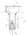
図1において、本発明の立坑施工機1の構造について説明する。図1に示すように、前記立坑施工機1は立坑の内面を保持するスキンプレート(筒体)80と、このスキンプレート80の下端部に設けられた掘削手段20と、スキンプレート80の上部内に設けられ、セグメント90を組み立てて土留めを行う組立手段(エレクター装置70)とを有する施工機本体10を備え、また施工機本体10を下方に推進させるための推進手段30を備える。なお、推進手段30は、後述するように立坑の構築位置に予め埋設された状態のドリルパイプ100から反力を取るようになっている。
【0016】
図1に示すように、前記掘削手段20として例えばカッターヘッド21を備え、前記カッターヘッド21の上部には、前記カッターヘッド21によって掘削された土砂を取り込むカッターチャンバ50を備える。前記カッターヘッド21は、周知のシールド機が備えるカッターヘッド21と同様である。前記カッターヘッド21は、軸回りに回転する円板状の基体24と、基体24の先端面に複数設けられたビット22と、カッターヘッド21に回転力を伝動する伝動部23等を備えている。
また前記カッターヘッド21の中心部は円形状の開口部25が設けられ、前記ドリルパイプ100が挿通可能になっている。
【0017】
さらに、前記カッターヘッド21を駆動させるための駆動手段として、カッター駆動モーター24をカッターヘッド21の上部に備え、前記カッター駆動モーター24には、前記カッターヘッド21のカッタートルクおよび回転速度を制御する制御手段を備えている。また、前記カッターヘッド21は駆動モーター24から旋回環26を介して回転する。
【0018】
また前記カッターチャンバ50と施工機本体10の上部とは、前記カッターチャンバ50内の上部に備えた閉塞プレート51で仕切られており、カッタチャンバ50内の泥水が立坑施工機本体10の上部に流入しないようになっている。
さらに、前記閉塞プレート51には、泥水循環装置40の送水管42と排泥管41のそれぞれの開口部44,45が設けられている。
【0019】
また、前記閉塞プレート51の中心部にはロータリー式止水機構52を備え、前記ドリルパイプ100が前記推進手段30から前記ロータリー式止水機構52を挿通し、さらに前記カッターヘッド21の開口部25を挿通し、施工機本体10の外部に延出している。
【0020】
さらに、前記泥水循環装置40の排泥管41にはスラリーポンプ43が接続されており、前記カッタチャンバ50内の泥水を坑外まで輸送される。そして、坑外まで送られた混合水は水と土砂とに分離され、水は再び送水用として送水管42からカッタチャンバ50内に送水される。
前記泥水循環装置40の送水管42と排泥管41に流量計を設置しても良い。
【0021】
図4は本発明の立坑施工機1の推進手段30周辺を拡大した様子を示している。図4に示すように、前記推進手段30は推進把持装置部31と推力伝達板部32からなり、前記推力伝達板部32は三角形状のリブ板32aを備え、前記リブ板32aの下部には、ドリルパイプ100を取り囲むように、等間隔に離間した複数本の油圧式のスラストジャッキ60が鉛直下方方向に備えられている。
【0022】
また、前記の推力伝達板部32のリブ板32a上面に推進把持装置部31が設けられている。
前記の推進把持装置部31の下端部31aと前記の推力伝達板部32の上端部32bはボルトで接合されており、前記ドリルパイプ100の後述する盛替え時には、前記ボルトを外し、前記推進把持装置部31を分割して前記ドリルパイプ100の中心軸から外側方向にスライドさせ、前記ドリルパイプ100を前記推進手段30から取り外すことが可能となる。
なお、推進把持装置部31は、複数の円弧板を接合することにより、円筒状となっている。また推進把持装置部31の内面には、後述する固定用ドリルパイプ100aの係合部110に対応して、周方向に沿った溝が上下に並んで複数設けられており、この部分がドリルパイプ100と推進手段30を固定する固定部33となっている。
【0023】
上記で示したように、前記ドリルパイプ100は複数のドリルパイプ100を一列に連接するように繋ぎ合わせ一体化させたものであるが、前記ドリルパイプ100の最上部の固定用ドリルパイプ100aの外壁に、前記固定部33に固定される位置に、固定部33と係合する係合部110が設けられている。
前記ドリルパイプ100の係合部110としては、例えばドリルパイプ100の周方向に沿った突状を複数上下に並んだ状態に設けており、上記のように固定部33には前記突条が嵌合するように溝を設けている。
このような構成により、推進把持装置部31は、各円弧板を固定用ドリルパイプ100aの係合部110を囲むようにして円筒状として、推力伝達板部32に接合することにより、固定用ドリルパイプ100aと推進把持装置部31が固定される。また、推進把持装置部31を推力伝達板部32から取り外して、各円弧板にばらすことにより、固定用ドリルパイプ100aと推進把持装置部31との固定を解除できる。
【0024】
また、上記の固定部33及び係合部110の構造は上記で説明したものに限定せず、例えば上記ドリルパイプ100の最上部の外壁に凹部を設け、立坑施工機1の推進把持装置31に前記の凹部と嵌合するように凸部を設ける構造でもよい。
【0025】
また、反力受け材となるドリルパイプ100は、ドリルパイプ100を用いてボーリングを行うことにより、ドリルパイプ100を立坑の施工位置に設置してもよいし、一度ドリルパイプ100もしくは他のドリル装置でボーリングを行い、一度ドリルパイプ100もしくは他のドリル装置を引き抜いた後にドリルパイプ100をボーリングされた穴に挿入するようにしても良い。
【0026】
また、ドリルパイプ100に代えてワイヤPC鋼線やその他の長尺な部材を反力受け材として用いることができる。なお、反力受け材をドリルパイプ100以外とした場合には、推進手段30と反力受け材の固定構造を代える必要があるが、ワイヤ等を固定する周知の方法を用いることができる。
また反力受け材の下端部を根固めする場合には、例えばボーリングの際に用いられるビッドを拡径可能な周知のものを用い、ボーリングされた穴の下端部に根固め用の空間を形成する。そして、反力受け材を挿入した状態で周知の根固め液を注入する。また、根固め液の注入には、ドリルパイプ100をパイプとして用いても良いし、ドリルパイプ100以外のものを反力受け材として用いた場合に、反力受け材とともに、根固め液を注入するチューブをボーリングされた穴に挿入しても良い。
【0027】
次に本発明の立坑施工機1の施工順序について説明する。
まず、本発明の立坑施工機1の反力受け材であるドリルパイプ100が地盤200に挿入可能なように、予め立坑を施工する位置でボーリングを行い、ボーリングがされた穴内に前記ドリルパイプ100を挿入する。
そして、所定の深度に立坑施工機1のドリルパイプ100の先端部が到達後、該先端部の開口部分から根固め液を射出して根固め部分150を造る。
【0028】
上記の場合、前記ドリルパイプ100に中空部を設け、前記ドリルパイプ100の上端部の開口部から、前記の根固め液を流し込むが、さらに根固め部分150を十分にするために、ボーリングによって掘削する穴の底部の周縁部に空間を設ける必要がある。
【0029】
前記の空間を設けるために、ボーリング時に使用する例えば掘削機のスパイラルオーガの先端に、杭の壁面方向に拡翼するビットを設ける。
まず、所定の深度までは、前記のスパイラルオーガで掘削し、前記のスパイラルオーガーの先端部が掘削予定の深度まで達したら、前記のビッドを拡げる。そして、前記のスパイラルオーガを上下に揺動させて、拡底部の径を軸部の径に対して広く設ける。
また前記根固め液の量は地盤200の性質等を考慮した上で射出する量を決定する。
【0030】
前記ドリルパイプ100の先端部で根固め部分150を造り、根固め部分150に十分な強度が発現すれば、次に前記ドリルパイプ100と施工機本体10を固定する。
前記ドリルパイプ100を施工機本体10に固定するには、前記固定ドリルパイプ100aの係合部110を、開放された前記推進把持装置部31の固定部33の位置に合わせ、前記推進把持装置部31をドリルパイプ100の中心軸から内側方向にスライドさせ、前記固定ドリルパイプ100aの係合部110を、前記推進把持装置部31の固定部33に嵌合させ、推力伝達板部32の上端部32bと推進把持装置部31の下端部31aをボルトで固定する。
【0031】
図1は、本発明の立坑施工機1で、立坑を掘削する途中の状態を示している。図1に示すように、立坑施工機1を推進させるには、まず泥水循環装置40の送水管42と排泥管41のバルブを開き、立坑施工機1のカッタチャンバ50内に送水を開始する。
【0032】
縦型シールド工法では、掘削がある程度以上の深さになると、推進時に立坑施工機1の前面に鉛直上向き方向に揚水圧がかかる。
このため、カッタチャンバ50内の泥水圧は、施工機本体10の前面にかかる揚水圧より高い圧力になるように制御する必要がある。
そこで、送水管42からの送水量と排泥管41からの排出量の割合を変化させることにより、カッターチャンバ50内の泥水圧を制御する。例えば、前記カッターチャンバ50内の泥水圧を高める場合、送水管42からの送水量を増加させ、排泥管41からの排出量を減少させる。
また、逆に前記カッターチャンバ50内の泥水圧を低下させるには、送水管42からの送水量を減少させ、また排泥管41からの排出量を増加させる。
【0033】
次に、施工機本体10の前面にあるカッターヘッド21を回転させ、切羽を開始する。前記カッターヘッド21は施工機本体10の前面の土砂を掘削し、掘削した土砂が施工機本体10のカッタチャンバ50内に送り込まれる。そして、前記カッタチャンバ50内で送水管42から送り込まれた水と混ざり排水管41の開口部44から吸引される。
【0034】
また、施工機本体10の下方に備えたカッターヘッド21にて土砂を掘削しながら、前記推進手段30のスラストジャッキ60を伸展し、前記施工機本体10を下方に推進させる。
前記スラストジャッキ60の伸展の速度は自由に設定可能で、また、施工機本体10を下方に推進させ、土砂がカッターヘッド21の前面に堆積し、カッタートルクが過大になる場合には、推進を停止させるとともに、前記スラストジャッキ60を所定の長さだけ縮小させ、カッターヘッド21の前面の土砂が取り除かれた状態で再び、前記スラストジャッキ60を伸ばしながら掘削する。
また、土砂のカッタチャンバ50内の堆積を防止するために、カッタチャンバ50内にアジテーター装置53を設ける。
【0035】
図1に示すように、地盤200とセグメント90の空隙には裏込め材250が注入されており、地盤200とセグメント90を一体化している。
またセグメント90と地盤200の間の空隙に施工機本体10のスキンプレート(筒体)80が挟まれた状態であり、そして、前記施工機本体10が下方に推進すると、前記スキンプレート(筒体)80の上端部分に新たな空隙が生じる。
【0036】
前記で新たな空隙に裏込め材250の注入を行い、地盤200とセグメント90を固定する。
前記裏込め材料250は地上で作液し、切羽現場まではパイプ圧送される。前記裏込め材料250の注入後は瞬時に高粘性となり、所定の強度を発現させ、セグメント90と地盤200とを一体化させる。
【0037】
図2は推進終了時の側面図を示している。図2に示すように、前記施工機本体10が下方に推進するにつれ、前記推進手段30のスラストジャッキ60は伸展し、前記スラストジャッキ60が最大限に伸展した時に推進を停止する。推進停止時に、立坑施工機1のカッターヘッド21のカッター駆動モーター24を停止させカッターヘッド21の回転を停止させる。また同時に泥水循環装置40を停止させ、前記カッターチャンバ50内への送水と排水を停止する。
【0038】
次に、セグメント90の組立とスラストの盛替えについて説明する。
図3に示すように、前記推進手段30のスラストジャッキ60が最大限に伸展するとカッターヘッド21の回転と泥水循環装置40を停止させる。そして、前記ドリルパイプ100を前記推進手段30の推進把持装置31から取り外して盛り替えの作業を行う。
【0039】
次に図4でスラスト盛替え時の手順について説明する。
まず上記で説明したように、立坑施工機1の推進手段30の推進把持装置部31には、前記ドリルパイプ100と施工機本体10を固定する固定部33を備え、前記ドリルパイプ100の最上部の外壁に、前記固定部33に固定される位置に、固定部33と係合する係合部110が設けられ固定されている。
前記ドリルパイプ100を開放するには、まず前記推進手段30の推力伝達板部32の上端部32bと、推進把持装置部31の下端部31aを固定しているボルトを外し、前記推進把持装置部31を立坑の壁面方向にスライドさせる。
【0040】
そして、前記ドリルパイプ100を前記推進把持装置部31から取り外し、係合部110を設けてある最上部の固定ドリルパイプ100aと最上部から2番目のドリルパイプ100b(以下第2ドリルパイプ)の連結を取り外し、固定ドリルパイプ100aを施工機内に仮置きする。そして、前記第2ドリルパイプ100bと最上部から3番目のドリルパイプ100c(以下第3ドリルパイプ)を切り離し、仮置きしてある固定ドリルパイプ100aと第3ドリルパイプ100cを連結する。第2ドリルパイプ100bは資材投入用クレーン300で地上に吊上げる。
【0041】
上記に示した作業と同時に、前記推進手段30のスラストジャッキ60を最大限に伸展した状態から前記スラストジャッキ60を最小限に縮め、前記推力伝達板部32及び推進把持装置部31を下方に降下させる。そして、上記の固定ドリルパイプ100aと第3ドリルパイプ100cを一体にした状態で、前記の固定ドリルパイプ100aの係合部110を、開放された前記推進把持装置部31の固定部33の位置に合わせ、前記推進把持装置部31をドリルパイプ100の中心軸から内側方向にスライドさせ、前記固定ドリルパイプ100aの係合部110を、前記推進把持装置部31の固定部33に嵌合させ、推力伝達板部32の上端部32bと推進把持装置部31の下端部31aをボルトで固定する。
【0042】
さらに、スラスト盛替え時にセグメント90の組立ても同時に行う。前記セグメント90は地上にて製造し、該セグメント90を資材投入用クレーン300で施工機本体10の上部のエレクター装置70に降ろす。
そして、前記エレクター装置70を立坑の内壁面の方向に移動させ、該内壁面の組立て位置まで移動させる。
また、前記のエレクター装置70を立坑の内周面に沿って旋回させながら、セグメント90を立坑の内壁に沿って組み立てる。
【0043】
セグメント90の組立てが終了後、再び推進の準備に入り、泥水循環装置40の送水管42と排泥管41のバルブを開き、施工機本体10のカッタチャンバ50内に送水を開始し、カッターヘッド21を回転させ、切羽を開始する。
【0044】
以上で説明した動作を繰り返しながら、立坑施工機1で掘削を続け、所定の深度まで立坑が完成すると、立坑施工機1のスキンプレート80内の装置を解体し、カッターヘッド21などの部品を資材投入用クレーン300にて吊りあげ回収する。
そして、立坑施工機1の回収が終了すると、立坑の底面にコンクリートを打設して底盤を形成する。
【0045】
また、前記セグメント90で土留めされた立坑内に鉄筋を配設し、コンクリートを打設して深礎抗を完成させる。
【0046】
【発明の効果】
請求項1記載の発明によれば、ボーリングされた穴に反力受け材を挿入し、前記反力受け材の下端部を根固めし、前記反力受け材の上部を施工機本体と固定することで、施工機本体を下方に推進させるための反力をとることができ、従来のように地上に大型の装置を必要とせずに掘削が可能となる。また、根固めを十分行えば、軟弱な地盤の掘削も可能となる。
【0047】
さらに、反力受け材としてドリルパイプを用いることにより、大深度の立坑を構築する場合に反力受け材が長くなっても、ドリルパイプを連接したり、外したりすることで、反力受け材の取り扱いを容易なものにできる。また、推進手段の固定部と係合する係合部を備えた固定用ドリルパイプの部分で、推進手段が常に反力を取るようになっているので、円筒状のドリルパイプから容易に反力が取れる。
【0048】
請求項2記載の発明によれば、立坑施工機を用いた立坑の施工方法で予め立坑を施工する位置でボーリングを行い、ボーリングされた穴に下端部が根固めされた状態の前記複数連接されたドリルパイプによる反力受け材を配置し、前記複数連接されたドリルパイプによる反力受け材から反力を取って施工機本体を下方に推進しながら、前記立坑施工機の下側を掘削するので、請求項1記載の発明と同様の効果を奏することができる。
【0049】
請求項3記載の発明によれば、深礎工法において、土留めされた立坑を構築する際に、請求項1記載の発明と同様の効果を奏することができる。
【図面の簡単な説明】
【図1】本発明の立坑施工機、立坑の施工方法及び深礎工法における一実施の形態で施工時の立坑施工機の推進開始時を説明する断面概略図である。
【図2】図1における施工時の立坑施工機の推進終了時を説明する断面図である。
【図3】図1における施工時の立坑施工機のセグメント組立て時及びスラスト盛替え時を説明する断面図である。
【図4】図1における施工時の立坑施工機のスラスト盛替え時の手順を説明する断面図である。
【符号の説明】
1 立坑施工機
10 施工機本体
20 掘削手段
21 カッターヘッド
22 ビット
30 推進手段
33 固定部
40 泥水循環装置
50 カッターチャンバ
60 スラストジャッキ
70 エレクター装置(組立手段)
80 スキンプレート(筒体)
90 セグメント
100 ドリルパイプ
110 係合部
150 根固め部分
200 地盤
250 裏込め材
300 資材投入用クレーン[0001]
TECHNICAL FIELD OF THE INVENTION
The present invention relates to a shaft construction machine for constructing an earth retaining shaft, a shaft construction method using the shaft construction machine, and a deep foundation method.
[0002]
[Prior art]
The deep foundation method has been used in the construction of urban areas and the construction of bridge foundations on cliffs.
The deep foundation method is a method of constructing a pile by digging down circularly with human power, retaining earth with a liner plate or reinforcing ring, burying it as a formwork, arranging reinforcement inside and placing concrete inside. The construction was possible in a small space.
However, the conventional deep foundation method is mainly performed by manual labor, and it is necessary to develop new construction technology by mechanization because of difficult work in narrow holes, safe work, and a decrease in the future workforce.
[0003]
Therefore, recently, a vertical shield method of excavating using a vertical shield machine has been receiving attention.
As a vertical shield method, for example, as shown in (Japanese Patent Laid-Open No. 6-313395), a pile is driven into a ground to a predetermined depth, and a vertical shield machine is provided so as to surround the pile. A method has been proposed in which the pile is gripped by a gripping device provided in the shaft construction machine and the pile is propelled as a reaction force.
[0004]
[Problems to be solved by the invention]
By the way, in the above method, a pile is first driven into a predetermined place in order to receive a reaction force at the time of starting of the shaft construction machine, but when building a large diameter and deep shaft, an extremely long pile is required. This is necessary, and a large pile driver for driving piles is required, which is problematic when the construction site is narrow.
[0005]
In addition, in the case of construction on soft ground, the pull-out drag of the pile may be insufficient as a reaction force when the shield starts.
[0006]
Accordingly, the present invention provides a vertical shield machine-like vertical shaft construction machine that does not require a long pile when constructing a vertical shaft, for example, in the construction of a deep foundation pile, a method for constructing a vertical shaft using this vertical shaft construction machine, and a method for constructing a vertical shaft. The purpose is to provide a foundation method.
[0007]
[Means for Solving the Problems]
In order to solve the above problems, the invention according to
[0008]
According to the first aspect of the invention, boring is performed in advance at a position where the shaft is to be constructed, and the reaction force receiving member is inserted into the bored hole. And, by fixing the lower end portion of the reaction force receiving material and fixing the upper portion of the reaction force receiving material to the construction machine body, it is possible to take a reaction force for propelling the construction machine body downward, Excavation can be performed without requiring a large device on the ground as in the related art. In addition, excavation of soft ground is possible if the foundation is sufficiently solidified.
[0009]
Further, the invention according to
[0010]
Therefore, according to the first aspect of the present invention, by using a drill pipe as a reaction force receiving material, even when the reaction force receiving material becomes long when a vertical shaft is constructed, the drill pipe is connected. By removing or removing, the handling of the reaction force receiving material can be facilitated. In addition, since the propulsion means always takes a reaction force at a portion of the fixing drill pipe having an engagement portion which engages with the fixing portion of the propulsion means, the reaction force can be easily generated from the cylindrical drill pipe. Can be taken.
[0011]
The invention according to claim 2 is a method for constructing a shaft using the shaft construction machine according to
[0012]
According to the invention of claim 2, boring is performed at a position where the shaft is to be constructed in advance by the method of constructing a shaft using a shaft construction machine, and the plurality of connected holes in a state where the lower end portion is solidified in the bored hole are connected. Drilling the lower side of the shaft construction machine while arranging a reaction force receiving material by a drill pipe and taking a reaction force from the reaction force receiving material by the plurality of connected drill pipes and propelling the construction machine body downward. Therefore, the same effect as the first aspect of the invention can be obtained.
[0013]
According to a third aspect of the present invention, there is provided a deep foundation method using the vertical shaft construction machine according to the first aspect, wherein boring is performed at a position on the ground where a vertical shaft is to be constructed, and a lower end portion is formed in a bored hole. A reaction force receiving material setting step of arranging a reaction force receiving material by the plurality of connected drill pipes in a hardened state, and then taking a reaction force from the reaction force receiving material by the plurality of connected drill pipes, Excavating the lower side of the shaft construction machine while propelling the construction machine downward by a predetermined distance, assembling the segments at the upper side of the shaft construction machine, and forming an annular shape corresponding to the distance excavated in the excavation process. It is characterized by including a shaft construction step of constructing a retaining wall, and a pile construction step of constructing a deep foundation pile in the retaining wall as a formwork for filling and burying the retaining wall.
[0014]
According to the third aspect of the invention, the same effect as that of the first aspect of the invention can be obtained when constructing an earth retaining shaft in the deep foundation method.
[0015]
In FIG. 1, the structure of the
[0016]
As shown in FIG. 1, for example, a
A
[0017]
Further, as a driving means for driving the
[0018]
Further, the
Further, the closing
[0019]
In addition, a rotary
[0020]
Further, a
A flow meter may be installed in the
[0021]
FIG. 4 shows an enlarged view of the vicinity of the propulsion means 30 of the
[0022]
A
The
In addition, the propulsion gripping
[0023]
As described above, the
As the engaging
With such a configuration, the propulsion gripping
[0024]
Further, the structures of the fixing
[0025]
Further, the
[0026]
Further, instead of the
When the lower end of the reaction force receiving material is to be solidified, for example, a well-known material capable of expanding the diameter of a bid used in boring is used, and a space for the solidification is formed at the lower end of the bored hole. I do. Then, a well-known root consolidation liquid is injected with the reaction force receiving member inserted. For injecting the consolidation liquid, the
[0027]
Next, the construction order of the
First, drilling is performed in advance at a position where a shaft is to be constructed so that the
After the tip of the
[0028]
In the above case, a hollow portion is provided in the
[0029]
In order to provide the space, a bit that expands in the direction of the wall surface of the pile is provided at the tip of a spiral auger of, for example, an excavator used during boring.
First, excavation is performed with the spiral auger up to a predetermined depth, and when the tip of the spiral auger reaches a depth to be excavated, the bid is expanded. Then, the spiral auger is swung up and down so that the diameter of the widened portion is larger than the diameter of the shaft portion.
The amount of the root compaction liquid is determined in consideration of the properties of the
[0030]
At the tip of the
In order to fix the
[0031]
FIG. 1 shows a state in which a shaft is being excavated by the
[0032]
In the vertical shield construction method, when the excavation reaches a certain depth or more, pumping pressure is applied vertically upward to the front surface of the
For this reason, it is necessary to control the muddy water pressure in the
Therefore, the mud pressure in the
Conversely, in order to decrease the muddy water pressure in the
[0033]
Next, the
[0034]
Further, while excavating earth and sand with the
The extension speed of the
Further, an
[0035]
As shown in FIG. 1, a
Further, the skin plate (tubular body) 80 of the construction machine
[0036]
The
The
[0037]
FIG. 2 shows a side view at the end of propulsion. As shown in FIG. 2, as the construction machine
[0038]
Next, assembling of the
As shown in FIG. 3, when the
[0039]
Next, the procedure at the time of thrust rearrangement will be described with reference to FIG.
First, as described above, the propulsion gripping
To open the
[0040]
Then, the
[0041]
Simultaneously with the operation described above, the
[0042]
Further, when the thrust is changed, the
Then, the
The
[0043]
After the assembly of the
[0044]
While the operation described above is repeated, digging is continued with the
When the collection of the
[0045]
In addition, a reinforcing steel bar is disposed in the shaft that has been earthed by the
[0046]
【The invention's effect】
According to the first aspect of the present invention, the reaction force receiving material is inserted into the bored hole, the lower end of the reaction force receiving material is fixed, and the upper portion of the reaction force receiving material is fixed to the construction machine body. As a result, a reaction force for propelling the construction machine body downward can be obtained, and excavation can be performed without requiring a large-sized device on the ground unlike the related art. In addition, excavation of soft ground is possible if the foundation is sufficiently solidified.
[0047]
Furthermore, by using a drill pipe as a reaction force receiving material, even if the reaction force receiving material becomes longer when constructing a deep shaft, the reaction force receiving material can be connected and removed by connecting and removing the drill pipe. Can be easily handled. In addition, since the propulsion means always takes a reaction force at a portion of the fixing drill pipe having an engagement portion which engages with the fixing portion of the propulsion means, the reaction force can be easily generated from the cylindrical drill pipe. Can be taken.
[0048]
According to the invention of claim 2, boring is performed at a position where the shaft is to be constructed in advance by the method of constructing a shaft using a shaft construction machine, and the plurality of connected pipes in a state where the lower end portion is solidified in the bored hole are connected. Drilling the lower side of the shaft construction machine while arranging a reaction force receiving material by a drill pipe and taking a reaction force from the reaction force receiving material by the plurality of connected drill pipes and propelling the construction machine body downward. Therefore, the same effect as the first aspect of the invention can be obtained.
[0049]
According to the third aspect of the invention, the same effect as that of the first aspect of the invention can be obtained when constructing an earth retaining shaft in the deep foundation method.
[Brief description of the drawings]
FIG. 1 is a schematic cross-sectional view illustrating a shaft construction machine, a shaft construction method and a deep foundation method according to an embodiment of the present invention at the time of starting the propulsion of the shaft construction machine at the time of construction.
FIG. 2 is a cross-sectional view for explaining the end of propulsion of a shaft construction machine at the time of construction in FIG.
FIG. 3 is a cross-sectional view illustrating a vertical shaft construction machine at the time of segment assembling and thrust rearrangement at the time of construction in FIG. 1;
FIG. 4 is a cross-sectional view for explaining a procedure at the time of thrust replacement of a shaft construction machine at the time of construction in FIG.
[Explanation of symbols]
DESCRIPTION OF
80 Skin Plate (Cylinder)
90
Claims (3)
掘削途中の立坑の先端部において立坑の内面を保持する筒体と、該筒体の下端部に設けられた掘削手段と、前記筒体の上部内に設けられ、セグメントを組み立てて環状の土留め壁を設ける組立手段とを有する施工機本体を備え、予め立坑を施工する位置でボーリングを行なうと共に、ボーリングされた穴の内部に反力受け材を挿入した状態とし、かつ、反力受け材の下端部を根固めした状態で、前記反力受け材から反力を取って前記掘削手段による掘削時に施工機本体を下方に推進させる推進手段を備え、
前記反力受け材が、複数連接されたドリルパイプとされるとともに、前記ドリルパイプには、前記推進手段に固定される固定用ドリルパイプが備えられ、前記推進手段には、前記固定用ドリルパイプに着脱自在に固定される固定部が設けられ、
前記固定用ドリルパイプの外周には、前記固定部に固定される位置に、固定部と係合する係合部が設けられ、
前記推進手段が、順次、前記施工機本体を下方に推進させる際に、前記固定用ドリルパイプより下側のドリルパイプの一部を取り除くとともに固定用ドリルパイプを残ったドリルパイプに接続させることで、固定用ドリルパイプを下方に移動させながら、該固定用ドリルパイプに前記固定手段を固定させて連接されて下端部が根固めされたドリルパイプから反力を取ることを特徴とする立坑施工機。A shaft construction machine for retaining an inner wall surface of the shaft while excavating the shaft,
A cylindrical body that holds the inner surface of the shaft at the tip of the shaft during excavation; a digging means provided at a lower end of the cylindrical body; A construction machine body having assembly means for providing a wall is provided, and boring is performed at a position where a shaft is to be constructed in advance, and a reaction force receiving material is inserted into the bored hole, and the reaction force receiving material is In a state where the lower end portion is solidified, a propelling means is provided for propelling the construction machine body downward during excavation by the excavating means by taking a reaction force from the reaction force receiving material,
The reaction force receiving member is a plurality of connected drill pipes, and the drill pipe includes a fixing drill pipe fixed to the propulsion means, and the propulsion means includes the fixing drill pipe. Is provided with a fixing portion that is detachably fixed to the
At the outer periphery of the fixing drill pipe, at a position fixed to the fixing portion, an engaging portion that engages with the fixing portion is provided,
The propulsion means, when sequentially propelling the construction machine body downward, by removing a part of the drill pipe below the fixing drill pipe and connecting the fixing drill pipe to the remaining drill pipe. Wherein the fixing drill is fixed to the fixing drill pipe while moving the fixing drill pipe downward, and a reaction force is taken from the drill pipe whose lower end is solidified and connected to the fixing means. .
地盤の立坑を施工すべき位置に、ボーリングを行うとともに、ボーリングされた穴内に下端部が根固めされた状態の前記複数連接されたドリルパイプによる反力受け材を配置する反力受け材設置工程と、
次いで、前記複数連接されたドリルパイプによる反力受け材から反力を取って前記立坑施工機を下方に所定の距離だけ推進しながら前記立坑施工機の下側を掘削する掘削工程と、
次いで、立坑施工機の上部側で、セグメントを組み立て、前記掘削工程で掘削された距離に対応して環状の土留め壁を構築する土留め工程とを備えるとともに、前記掘削工程と土留め工程とを繰り返し行なって所定の深さまで土留めされた状態の立坑を形成することを特徴とする立坑の施工方法。A method for constructing a shaft using the shaft construction machine according to claim 1,
A reaction force receiving member installation step of performing boring at a position where a ground shaft is to be constructed, and arranging a reaction force receiving material by the plurality of connected drill pipes in a state where the lower end portion is solidified in the bored hole When,
Then, a drilling step of excavating the lower side of the shaft construction machine while taking a reaction force from the reaction force receiving material by the plurality of connected drill pipes and propelling the shaft construction machine downward by a predetermined distance.
Subsequently, on the upper side of the shaft construction machine, while assembling the segments, including a retaining step of constructing an annular retaining wall corresponding to the distance excavated in the excavating step, the excavating step and the retaining step Is performed repeatedly to form a shaft which is retained to a predetermined depth.
地盤の立坑を施工すべき位置に、ボーリングを行なうとともに、ボーリングされた穴内に下端部が根固めされた状態の前記複数連接されたドリルパイプによる反力受け材を配置する反力受け材設置工程と、
次いで、前記複数連接されたドリルパイプによる反力受け材から反力を取って前記立坑施工機を下方に所定の距離だけ推進しながら前記立坑施工機の下側を掘削するとともに、立坑施工機の上部側で、セグメントを組み立て、前記掘削工程で掘削された距離に対応して環状の土留め壁を構築する立坑施工工程と、
次いで、土留め壁を埋め殺しの型枠として土留め壁内に深礎杭を構築する杭施工工程とを備えることを特徴とする深礎工法。A deep foundation method using the shaft construction machine according to claim 1,
A reaction force receiving member installation step of performing boring at a position where a vertical shaft is to be constructed, and arranging a reaction force receiving material by the plurality of connected drill pipes in a state where the lower end portion is solidified in the bored hole When,
Next, while taking a reaction force from the reaction force receiving material by the plurality of connected drill pipes and propelling the shaft construction machine downward by a predetermined distance, excavating the lower side of the shaft construction machine, On the upper side, assembling the segments, a shaft construction process of building an annular retaining wall corresponding to the distance excavated in the excavation process,
Then, a pile construction process for constructing a deep foundation pile in the retaining wall as a formwork for filling and killing the retaining wall.
Priority Applications (1)
| Application Number | Priority Date | Filing Date | Title |
|---|---|---|---|
| JP2001154044A JP3545723B2 (en) | 2001-05-23 | 2001-05-23 | Shaft construction machine, shaft construction method and deep foundation method |
Applications Claiming Priority (1)
| Application Number | Priority Date | Filing Date | Title |
|---|---|---|---|
| JP2001154044A JP3545723B2 (en) | 2001-05-23 | 2001-05-23 | Shaft construction machine, shaft construction method and deep foundation method |
Publications (2)
| Publication Number | Publication Date |
|---|---|
| JP2002349181A JP2002349181A (en) | 2002-12-04 |
| JP3545723B2 true JP3545723B2 (en) | 2004-07-21 |
Family
ID=18998461
Family Applications (1)
| Application Number | Title | Priority Date | Filing Date |
|---|---|---|---|
| JP2001154044A Expired - Fee Related JP3545723B2 (en) | 2001-05-23 | 2001-05-23 | Shaft construction machine, shaft construction method and deep foundation method |
Country Status (1)
| Country | Link |
|---|---|
| JP (1) | JP3545723B2 (en) |
Families Citing this family (1)
| Publication number | Priority date | Publication date | Assignee | Title |
|---|---|---|---|---|
| CN107288640B (en) * | 2016-04-13 | 2019-07-30 | 中国黄金集团建设有限公司 | A kind of nothing is surely restricted self-supporting modularization vertical shaft driving and masonry construction device |
-
2001
- 2001-05-23 JP JP2001154044A patent/JP3545723B2/en not_active Expired - Fee Related
Also Published As
| Publication number | Publication date |
|---|---|
| JP2002349181A (en) | 2002-12-04 |
Similar Documents
| Publication | Publication Date | Title |
|---|---|---|
| JP2002155530A (en) | Embedding method and tip metal fitting of existing pile | |
| JP5852038B2 (en) | Construction method of on-site cast-in-place concrete piles and steel pipes with excavation blades | |
| JP3545723B2 (en) | Shaft construction machine, shaft construction method and deep foundation method | |
| JP3663155B2 (en) | Widening excavation apparatus and widening excavation method | |
| JP3165997B2 (en) | Casting method and equipment for sheet piles | |
| KR101702180B1 (en) | A Displacement Bored Pile Method with Impermeable and Detachable Casing Shoe | |
| JP2942779B1 (en) | Underground wall construction method | |
| US4027490A (en) | Self-sinking, axial passage foundation pile and method | |
| JPH03257215A (en) | Pile constructing method | |
| JP2000144727A (en) | Construction method of footing pile | |
| JP3673171B2 (en) | Concrete pile setting method | |
| JP6952159B1 (en) | Pile excavation backfill method | |
| JP4006838B2 (en) | Drilling and stirring method and equipment | |
| JP3676850B2 (en) | Steel pile construction method | |
| JP2023150433A (en) | Foundation structure construction method | |
| JPH06100080B2 (en) | Large-section tunnel construction method and ground solidification column construction device | |
| JP2840024B2 (en) | Vertical hole forming method | |
| JPH0258626A (en) | Constructing method for foundation | |
| JPH10102966A (en) | Excavating equipment of cast-in-place concrete pile hole | |
| JP2005097853A (en) | Excavator with vertically movable rotary table, steel pipe pile driving method based on double-pipe system, and excavation method for construction of foundation pile | |
| JPH0321719A (en) | Pile driving method | |
| JPH07238543A (en) | Execution method of wide flange beam pile | |
| JP3744031B2 (en) | Drilling tools and methods | |
| JPH0213610A (en) | Water-stopping and sheeting wall construction method | |
| JPH0893399A (en) | Peripheral wall structure of foundation of large sectional underground space, excavation method and device thereof |
Legal Events
| Date | Code | Title | Description |
|---|---|---|---|
| A977 | Report on retrieval |
Free format text: JAPANESE INTERMEDIATE CODE: A971007 Effective date: 20040122 |
|
| A131 | Notification of reasons for refusal |
Free format text: JAPANESE INTERMEDIATE CODE: A131 Effective date: 20040203 |
|
| A521 | Written amendment |
Free format text: JAPANESE INTERMEDIATE CODE: A523 Effective date: 20040315 |
|
| TRDD | Decision of grant or rejection written | ||
| A01 | Written decision to grant a patent or to grant a registration (utility model) |
Free format text: JAPANESE INTERMEDIATE CODE: A01 Effective date: 20040406 |
|
| A61 | First payment of annual fees (during grant procedure) |
Free format text: JAPANESE INTERMEDIATE CODE: A61 Effective date: 20040408 |
|
| R150 | Certificate of patent or registration of utility model |
Free format text: JAPANESE INTERMEDIATE CODE: R150 |
|
| R250 | Receipt of annual fees |
Free format text: JAPANESE INTERMEDIATE CODE: R250 |
|
| FPAY | Renewal fee payment (event date is renewal date of database) |
Free format text: PAYMENT UNTIL: 20080416 Year of fee payment: 4 |
|
| FPAY | Renewal fee payment (event date is renewal date of database) |
Free format text: PAYMENT UNTIL: 20100416 Year of fee payment: 6 |
|
| FPAY | Renewal fee payment (event date is renewal date of database) |
Free format text: PAYMENT UNTIL: 20110416 Year of fee payment: 7 |
|
| FPAY | Renewal fee payment (event date is renewal date of database) |
Free format text: PAYMENT UNTIL: 20130416 Year of fee payment: 9 |
|
| FPAY | Renewal fee payment (event date is renewal date of database) |
Free format text: PAYMENT UNTIL: 20130416 Year of fee payment: 9 |
|
| FPAY | Renewal fee payment (event date is renewal date of database) |
Free format text: PAYMENT UNTIL: 20140416 Year of fee payment: 10 |
|
| R250 | Receipt of annual fees |
Free format text: JAPANESE INTERMEDIATE CODE: R250 |
|
| R250 | Receipt of annual fees |
Free format text: JAPANESE INTERMEDIATE CODE: R250 |
|
| LAPS | Cancellation because of no payment of annual fees |