JP3545552B2 - Plate making method and apparatus for heat-sensitive stencil paper - Google Patents
Plate making method and apparatus for heat-sensitive stencil paper Download PDFInfo
- Publication number
- JP3545552B2 JP3545552B2 JP29582896A JP29582896A JP3545552B2 JP 3545552 B2 JP3545552 B2 JP 3545552B2 JP 29582896 A JP29582896 A JP 29582896A JP 29582896 A JP29582896 A JP 29582896A JP 3545552 B2 JP3545552 B2 JP 3545552B2
- Authority
- JP
- Japan
- Prior art keywords
- stencil sheet
- light
- emitting device
- heat
- stencil
- Prior art date
- Legal status (The legal status is an assumption and is not a legal conclusion. Google has not performed a legal analysis and makes no representation as to the accuracy of the status listed.)
- Expired - Fee Related
Links
Images

Landscapes
- Manufacture Or Reproduction Of Printing Formes (AREA)
Description
【0001】
【発明の属する技術分野】
本発明は感熱孔版原紙の製版方法及び製版装置に関し、詳しくは、感熱孔版原紙の表面に画像を再現するように光熱変換材料を転移させた後、可視光線又は赤外線を照射して前記光熱変換材料を発熱させて前記孔版原紙に前記画像状の穿孔を形成して製版する感熱孔版原紙の製版方法及び装置に関する。
【0002】
【従来の技術】
近年、孔版印刷に使用される孔版原紙は、熱可塑性樹脂フィルム単独、または、該樹脂フィルムとこれに積層された和紙等のインキ通過性の多孔質支持体とからなる感熱孔版原紙が一般的である。
【0003】
かかる感熱孔版原紙は、複数個の発熱素子をドットマトリックス状に配列してなるサーマルヘッドに密着させることよって溶融穿孔し、製版することができる。しかし、この場合、サーマルヘッドと孔版原紙との押し付け圧の不均一に起因する穿孔不良が生じ、また、製版時に孔版原紙に皺が発生したり、孔版原紙の搬送不良が起こることもあった。
【0004】
そこで、本出願人は、特願平7−284610号において、液体中に含有せしめた光熱変換材料を該液体とともに液体吐出装置から感熱孔版原紙上に吐出して該感熱孔版原紙に転移させた後、該感熱孔版原紙に可視光線又は赤外線を照射して、該光熱変換材料が転移した該感熱孔版原紙の部位を選択的に穿孔して製版することを特徴とする感熱孔版原紙の製版方法を提案した。
【0005】
この製版方法は、光熱変換材料を含有する液体を、感熱孔版原紙と非接触状態の液体吐出装置から該孔版原紙上に吐出して該光熱変換材料を該孔版原紙に転移させる第1工程と、発光装置を用いて該孔版原紙に可視光線又は赤外線を照射して、該光熱変換材料が転移した該孔版原紙の部位を選択的に穿孔する第2工程とからなる。
【0006】
この製版方法によれば、製版時に、液体吐出装置及び発光装置の何れも孔版原紙に接触することがなく、すなわち、従来の製版方法におけるような孔版原紙とサーマルヘッドとの密着を要することもないので、かかる密着不良に起因する穿孔不良の問題も生じることがなく、画像情報に忠実な製版が行なわれる点で好都合である。
【0007】
【発明が解決しようとする課題】
しかし、上記第2工程で用いる発光装置としては一般にフラッシュランプが用いられ、サーマルヘッドに比べて縦横の寸法が大きい。したがって、サーマルヘッドと同様に孔版原紙の幅方向に対応した発光装置を設けるとすれば、発光装置全体の大きさはサーマルヘッドよりもかなり大きくなる。
【0008】
また、一般的にフラッシュランプはそのサイズが大きくなるにつれ、孔版原紙の製版に必要な光量を出力するために必要とされる電力蓄積コンデンサの容量が大きくなる。電力蓄積コンデンサの容量が大きくなるにつれ、その充電時間も長くなり、繰り返しの発光には不利になる。また、フラッシュランプ自体のコスト含め、全体のコストも高くなる。
【0009】
本発明は、冒頭で述べた感熱孔版原紙の製版方法において、小型の発光装置を用いて容易に製版できるようにするとともに、製版装置全体を小型化、軽量化及び単純化することを目的とする。
【0010】
【課題を解決するための手段】
本発明によれば、上記目的は、感熱孔版原紙の表面に画像を再現するように光熱変換材料を転移させた後、可視光線又は赤外線を照射して前記光熱変換材料を発熱させて前記孔版原紙に前記画像状の穿孔を形成して製版する感熱孔版原紙の製版方法において、前記孔版原紙の表面の上方で移動可能な架台に取り付けられ、前記孔版原紙の表面の一部分に可視光線又は赤外線を照射する発光装置及び前記架台と同一の架台に取り付けられた光熱変換材料吐出装置を用い、前記架台により前記光熱変換材料吐出装置及び前記発光装置を一緒に移動させることにより、当該光熱変換材料吐出装置から前記光熱変換材料を吐出して前記孔版原紙の表面に転移させ、前記孔版原紙の表面の所望の部分に可視光線又は赤外線を照射することを特徴とする感熱孔版原紙の製版方法によって達成される。
【0011】
本発明の製版方法において、前記孔版原紙はプラテンローラのような搬送手段によって一方向に搬送し、前記発光装置はレールに沿って摺動する架台等に取り付けて、前記孔版原紙の前記搬送方向に直交する方向に移動できるようにすれば、前記孔版原紙の表面の所望の部分に照射を容易に施すことできる。
【0012】
このように、本発明によれば、発光装置が孔版原紙の所望の部分に移動可能とされているため、大型の発光装置を用いる必要がなく、小型の発光装置を用いればよく、これを実施する装置も小型、軽量、単純化できる。
【0013】
本発明において、発光装置は、キセノンランプ、フラッシュランプ、ハロゲンランプ、赤外線ヒーター等を用いることができ、さらに、孔版原紙の表面が概略矩形に照射されるように、適当な反射板と組み合わせると好都合である。このように、孔版原紙の表面を概略矩形部分毎に照射できる発光装置を用いれば、A)前記孔版原紙を静止させたまま、前記発光装置を摺動して発光させて、前記孔版原紙の前記搬送方向に直交する帯状部分全体を照射する第一工程と、B)照射された前記帯状部分に隣接する未照射部分と前記発光装置とが対向するように前記孔版原紙を前記搬送方向に搬送する第二工程と、を繰り返すことにより前記孔版原紙全体に照射して製版することができる。この場合、孔版原紙の表面全体に切れ目無く照射を施すために、照射される前記矩形部分は、これと隣接する同様の矩形部分と、前記搬送方向及びこれと直交する方向に互いに部分的に重なり合うようにすることが好ましい。
【0014】
本発明の製版方法は、感熱孔版原紙を搬送する搬送装置と、前記孔版原紙の表面の上方で前記搬送方向に直交する方向に移動可能な架台に取り付けられた発光装置及び前記架台と同一の架台に取り付けられ、前記架台により前記発光装置と一緒に移動される光熱変換材料吐出装置とを備えてなる発光型製版装置によって実施することができる。
【0015】
本発明の製版装置は、一つの装置で上記第一工程及び第二工程を実施可能とするために、感熱孔版原紙の表面に画像を再現するように光熱変換材料を吐出して転移させる光熱変換材料吐出装置を備えていることが好ましい。かかる吐出装置としては、例えば、1インチ当たり10〜2000個(10〜2000dpi)の開口部を有するノズル、スリット、多孔質材、多孔フィルム等を圧電素子、送液ポンプ等に接続し、光熱変換材料を含有する液体を文字及び模様等画像の電気的信号に従って間欠的又は連続的に、即ち、ドット状又はライン状に吐出するようにした装置が挙げられる。
【0016】
本発明の製版装置において、該吐出装置は、発光装置と同様の架台に取り付けられて、両者は該架台によって一緒に移動されるようにされていてもよく、また、孔版原紙の表面の上方でその搬送方向に直交する方向に移動可能な別の架台に取り付けられていてもよい。
【0017】
なお、本発明で用いる感熱孔版原紙、光熱変換材料及び該光熱変換材料を含有させる液体については、特願平7−284610号、特願平8−54103号等に記載のものを使用することができ、その詳細については当該出願明細書を参照されたい。
【0018】
以下、図面を参照しつつ、本発明の具体例を説明するが、本発明は以下の具体例のみに限定されるものではない。
【0019】
【発明を実施するための形態】
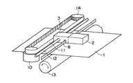
図1は本発明の製版装置の一具体例を示す斜視図である。該製版装置は、感熱孔版原紙1をその長手方向に搬送するプラテンローラ13を備えるとともに、該孔版原紙1の長手方向と直交する方向、即ち、孔版原紙1の幅方向に摺動可能な発光装置2を備えている。該発光装置2は架台3に取り付けられている。該架台3は、孔版原紙1の幅方向の両側に夫々配置された駆動モーター10とアイドルローラ14との間に架け渡された駆動ベルト11に連結し、孔版原紙1の幅方向に延在するレール12に沿って摺動する。これによって、発光装置2は、駆動ベルト11の動きに連動して孔版原紙1の表面から上方に僅かな間隔をおいて、孔版原紙1の幅方向に左右に摺動できるようにされている。
【0020】
架台3は、レール12と平行に配置された帯8を挿通して摺動する。該帯8は、印字解像度1ドット毎に白黒と変化する鉛直方向縞模様が形成された平面状の帯であり、架台3の移動に伴う白黒の変化を架台3に内蔵された光センサ(図示せず)によって読み、これをエンコーダパルスとして帯8の端からのエンコーダパルス数を加算、減算することによって、該端からの架台3の移動距離を割り出し、駆動モータ10の駆動を制御して、発光装置2の移動位置を制御できるようにしている。
【0021】
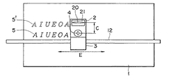
図2は、図1の装置の底面図である。図2から明らかなように、発光装置2は、孔版原紙1と対向する面にフラッシュランプ20を備えるとともにその周囲に矩形の反射板21を備えて、孔版原紙1の表面を概略矩形状に照射するようにされている。また、発光装置2の前記と同一の面には、架台3に隣接して、液体吐出装置4が設けられている。該液体吐出装置4は、通常のインクジェット方式のプリンタに用いられている印字ヘッドを利用したものであり、適当なモノクロ印刷用インキカートリッジ(図示せず)からカーボンブラック等の光熱変換材料を含有する液体を孔版原紙1上にドットマトリックス状に吐出することができる。このように、同一の架台3に発光装置2と液体吐出装置4を具備させることにより、装置全体を小型化することができる。
【0022】
製版時、まず、図2の矢印Eで示される架台摺動方向に、架台3をレール12に沿って移動させながら、液体吐出装置4から光熱変換材料を含有する液体を孔版原紙1上に吐出して、文字又は線図等の画像(図2ではAIUEOAの文字)として光熱変換材料5を孔版原紙1上に転移させる。その後、プラテンローラ13によって孔版原紙1を、発光装置2と液体吐出装置4との中心間距離Cだけ移動させる。そして、再び、架台3をレール12に沿って移動させながら、発光装置2から前記画像上に可視光線又は赤外線を照射すると、光熱変換材料が発熱して孔版原紙1に前記画像に対応する穿孔5′が形成され、かくして、孔版原紙1の製版が行なわれる。発光装置2の発光と同時に、液体吐出装置4から前記液体を孔版原紙1に吐出させて、前記穿孔5′に隣接させて光熱変換材料を文字又は線図等の画像5として転移させれば、製版時間の短縮が図られる。かかる発光装置2の摺動と孔版原紙の搬送を繰り返すことにより、孔版原紙1の全体に製版を行うことができることは明らかである。なお、架台3の位置は上記エンコーダパルスによって監視されているので、発光装置2の発光のタイミングと液体吐出装置の吐出のタイミングは、架台3の位置との関係を適切にプログラミングすることにより容易にコンピュータ制御することができる。
【0023】
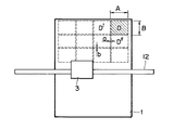
発光装置2の発光は移動とともに連続的に行うことも可能であるが、図3に示すように、発光装置2は孔版原紙1の幅A及び長さBの概略矩形部分Dを一括して照射することができるため、孔版原紙1を該矩形部分毎に断続的に発光させることが好ましい。図3では、発光装置2が一度に照射可能な範囲が幅A長さBの矩形部分Dであるため、孔版原紙1を幅方向に幅A長さBの4つの矩形製版部分に分割し、該部分毎に4回にわけて断続的に照射をする図式を示している。この場合、孔版原紙1を長さBだけ送る毎に、架台3をレール12に沿って孔版原紙1を横断させ、その間、架台3が幅Aだけ移動する毎に発光装置2を発光させれば、孔版原紙1を幅方向に帯状に製版することができる。この孔版原紙1の長手方向への搬送工程と発光装置2の幅方向への搬送及び発光工程を交互に繰り返せば、最終的には孔版原紙1の表面全体に照射することができる。
【0024】
図3のように孔版原紙1を分割製版する場合、孔版原紙1全体を均一に製版するために、上記矩形部分Dが、これと縦方向及び横方向で隣接する矩形部分D′及びD″と一部重複するようにすることが好ましい。本発明の装置において、かかる重複幅aを得るためには、図4に示されるように、架台3の移動距離を調整することにより容易に行うことができ、重複長bを得るためには、孔版原紙1のプラテンローラ13による移動距離を調整することにより容易に行うことができる。
【0025】
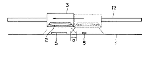
なお、液体吐出装置4から吐出される光熱変換材料含有液体が孔版原紙1の表面に転移した後、その乾燥が不十分な状態で発光装置2を発光させると、製版効率を著しく低下させる要因となる。これを解消するためには、光熱変換材料が十分に乾燥した後に発光装置2からの照射を受けるようにすることが望ましい。別法としては、図5に示されるように、発光装置2と光熱変換材料5が転移した孔版原紙1との間に送風する送風機7を設けたり、孔版原紙1を加熱する電熱器6等の加熱手段を設けることにより、光熱変換材料の乾燥を促進させることもできる。
【0026】
【発明の効果】
本発明によれば、感熱孔版原紙を、他の装置に接触させることなく、非接触製版できるだけでなく、可動の発光装置を用いるため、孔版原紙の寸法や製版領域の大小にかかわらず、小型の発光装置を用いて孔版原紙やその製版領域の全体を製版することができる。また、光熱変換材料が転移した部分のみに対して発光するように制御することもできるので、製版時間を短くすることも可能である。
【0027】
また、小型の発光装置を採用することにより、製版装置のコストを低減できるのみならず、光熱変換材料の吐出装置と発光装置を同一の架台に組み込むことにより、製版装置を小型化できるとともに、その構造を単純化することもできる。また、所望の製版領域に数回発光して、発光エネルギーを変化させることもできるので、孔版原紙の穿孔状態を部分的に変化させることも可能である。
【図面の簡単な説明】
【図1】本発明の感熱孔版原紙製版装置の一具体例を示す模式的斜視図である。
【図2】図1の装置の模式的底面図である。
【図3】図1の発光装置を用いて孔版原紙を矩形部分毎に分割製版する図式を示す模式的平面図である。
【図4】図3の発光装置の製版動作を示す模式的側面図である。
【図5】本発明の製版装置の他の具体例を示す側面図である。
【符号の説明】
1 感熱孔版原紙
2 発光装置
3 架台
4 液体吐出装置
5 光熱変換材料
5′ 穿孔
6 加熱器
7 送風機
8 帯
10 駆動モータ
11 駆動ベルト
12 レール
13 プラテンローラ
14 アイドルローラ
20 フラッシュランプ
21 反射板
A 製版部分幅
B 製版部分長
C 中心間距離
D、D′、D″ 矩形部分
E 架台摺動方向
a 重複幅
b 重複長[0001]
TECHNICAL FIELD OF THE INVENTION
The present invention relates to a method and apparatus for making a heat-sensitive stencil sheet, specifically, after transferring a light-to-heat conversion material so as to reproduce an image on the surface of the heat-sensitive stencil sheet, irradiating visible light or infrared light with the light-to-heat conversion material. The present invention relates to a method and an apparatus for making a heat-sensitive stencil sheet for making a stencil sheet by forming the image-like perforations in the stencil sheet by generating heat.
[0002]
[Prior art]
In recent years, a stencil sheet used for stencil printing is generally a thermosensitive stencil sheet composed of a thermoplastic resin film alone or an ink-permeable porous support such as Japanese paper laminated on the resin film. is there.
[0003]
Such a heat-sensitive stencil sheet can be perforated by being melt-punched by bringing a plurality of heating elements into close contact with a thermal head having a dot matrix arrangement. However, in this case, poor perforation occurs due to uneven pressing pressure between the thermal head and the stencil sheet, and wrinkles may occur on the stencil sheet during stencil making, or stencil conveyance failure may occur.
[0004]
In view of this, the present applicant has disclosed in Japanese Patent Application No. Hei 7-284610 that a photothermal conversion material contained in a liquid is discharged together with the liquid from a liquid discharger onto a heat-sensitive stencil sheet and transferred to the heat-sensitive stencil sheet. Irradiating the heat-sensitive stencil base paper with visible light or infrared light, and selectively perforating a portion of the heat-sensitive stencil base paper to which the light-to-heat conversion material is transferred to form a stencil; did.
[0005]
This stencil making method comprises: a first step of discharging a liquid containing a light-to-heat conversion material onto the stencil sheet from a liquid discharger in a non-contact state with the heat-sensitive stencil sheet to transfer the light-to-heat conversion material to the stencil sheet; A second step of irradiating the stencil paper with visible light or infrared light using a light-emitting device to selectively perforate a portion of the stencil paper to which the photothermal conversion material has been transferred.
[0006]
According to this plate making method, neither the liquid discharge device nor the light emitting device comes into contact with the stencil sheet at the time of plate making, that is, there is no need for close contact between the stencil sheet and the thermal head as in the conventional plate making method. Therefore, there is no problem of poor perforation due to such poor adhesion, and this is advantageous in that plate making faithful to image information is performed.
[0007]
[Problems to be solved by the invention]
However, a flash lamp is generally used as a light emitting device used in the second step, and has a larger vertical and horizontal dimension than a thermal head. Therefore, if a light emitting device corresponding to the width direction of the stencil sheet is provided similarly to the thermal head, the size of the entire light emitting device becomes considerably larger than that of the thermal head.
[0008]
In general, as the size of a flash lamp increases, the capacity of a power storage capacitor required to output a light amount required for stencil making of stencil paper increases. As the capacity of the power storage capacitor increases, its charging time also increases, which is disadvantageous for repeated light emission. In addition, the overall cost including the cost of the flash lamp itself increases.
[0009]
SUMMARY OF THE INVENTION It is an object of the present invention to provide a method for making a heat-sensitive stencil sheet described at the beginning, wherein a plate can be easily made using a small light emitting device, and the entire plate making device is reduced in size, weight and simplification. .
[0010]
[Means for Solving the Problems]
According to the present invention, the object is to transfer a light-to-heat conversion material so as to reproduce an image on the surface of a heat-sensitive stencil sheet, and then irradiate visible light or infrared light to cause the light-to-heat conversion material to generate heat, so that the stencil sheet is heated. In the method of making a heat-sensitive stencil sheet for forming a stencil sheet by forming an image-shaped perforation, the stencil sheet is mounted on a mount movable above the surface of the stencil sheet, and irradiates a part of the surface of the stencil sheet with visible light or infrared light. using a photothermal conversion material discharge device attached to the light emission device and the frame of the same frame you, by moving the light-heat conversion material discharge device and the light emitting device together by the frame, the photothermal conversion material discharge from the device by ejecting the photothermal conversion material is transferred to the surface of the stencil sheet, feeling and irradiating the the visible or infrared ray to a desired portion of the surface of said stencil sheet It is achieved by a method for making the stencil sheet.
[0011]
In the stencil making method of the present invention, the stencil sheet is conveyed in one direction by conveying means such as a platen roller, and the light emitting device is attached to a stand or the like that slides along a rail, in the conveying direction of the stencil sheet. If the stencil paper can be moved in the orthogonal direction, it is possible to easily irradiate a desired portion on the surface of the stencil sheet.
[0012]
As described above, according to the present invention, since the light emitting device can be moved to a desired portion of the stencil sheet, it is not necessary to use a large light emitting device, and a small light emitting device may be used. The device to be used can be small, light and simple.
[0013]
In the present invention, a xenon lamp, a flash lamp, a halogen lamp, an infrared heater, or the like can be used as the light emitting device. Further, when the light emitting device is combined with an appropriate reflecting plate so that the surface of the stencil paper is irradiated in a substantially rectangular shape, it is convenient. It is. As described above, by using the light emitting device that can irradiate the surface of the stencil sheet into each of the substantially rectangular portions, A) slide the light emitting device to emit light while keeping the stencil sheet stationary, and A first step of irradiating the entire strip portion orthogonal to the transport direction; and B) transporting the stencil sheet in the transport direction such that the non-irradiated portion adjacent to the irradiated strip portion and the light emitting device face each other. By repeating the second step, the entire stencil sheet can be irradiated to perform plate making. In this case, in order to irradiate the entire surface of the stencil sheet without interruption, the irradiated rectangular portion partially overlaps a similar rectangular portion adjacent thereto in the transport direction and a direction orthogonal thereto. It is preferable to do so.
[0014]
The stencil making method of the present invention includes a conveying device that conveys the heat-sensitive stencil sheet, a light-emitting device attached to a pedestal movable above the surface of the stencil sheet in a direction orthogonal to the conveying direction, and the same pedestal as the pedestal. And a light-to-heat conversion material discharging device which is attached to the light-emitting device and is moved together with the light-emitting device by the gantry .
[0015]
The plate making device of the present invention is a photo-thermal conversion device that discharges and transfers a photo-thermal conversion material so as to reproduce an image on the surface of a heat-sensitive stencil sheet so that the first step and the second step can be performed by one device. It is preferable to provide a material discharge device. As such a discharge device, for example, a nozzle having 10 to 2,000 openings (10 to 2,000 dpi) per inch, a slit, a porous material, a porous film, or the like is connected to a piezoelectric element, a liquid sending pump, or the like, and photothermal conversion is performed. There is an apparatus in which a liquid containing a material is ejected intermittently or continuously, that is, in a dot shape or a line shape according to an electric signal of an image such as a character and a pattern.
[0016]
In the stencil making apparatus of the present invention, the discharge device may be attached to a base similar to the light emitting device, and both may be moved together by the base. It may be attached to another stand that can move in a direction perpendicular to the transport direction.
[0017]
As the heat-sensitive stencil paper, light-to-heat conversion material and liquid containing the light-to-heat conversion material used in the present invention, those described in Japanese Patent Application Nos. 7-284610 and 8-54103 can be used. Yes, refer to the specification for details.
[0018]
Hereinafter, specific examples of the present invention will be described with reference to the drawings, but the present invention is not limited to only the following specific examples.
[0019]
BEST MODE FOR CARRYING OUT THE INVENTION
FIG. 1 is a perspective view showing a specific example of the plate making apparatus of the present invention. The stencil making apparatus includes a platen roller 13 for transporting the
[0020]
The
[0021]
FIG. 2 is a bottom view of the apparatus of FIG. As is apparent from FIG. 2, the
[0022]
At the time of plate making, first, the liquid containing the photothermal conversion material is discharged onto the
[0023]
The light emission of the
[0024]
When the
[0025]
After the liquid containing the photothermal conversion material discharged from the
[0026]
【The invention's effect】
According to the present invention, the heat-sensitive stencil sheet can be made in a non-contact manner without making contact with another apparatus, and a movable light-emitting device is used. The stencil sheet and the entire stencil making area can be stenciled using the light emitting device. In addition, since it is possible to control so as to emit light only at the portion where the light-to-heat conversion material is transferred, it is possible to shorten the plate making time.
[0027]
In addition, not only can the cost of the plate making device be reduced by employing a small light emitting device, but also the plate making device can be downsized by incorporating the light-to-heat conversion material discharge device and the light emitting device on the same base. The structure can be simplified. In addition, since the light emission energy can be changed by emitting light several times to a desired stencil making region, the perforated state of the stencil sheet can be partially changed.
[Brief description of the drawings]
FIG. 1 is a schematic perspective view showing a specific example of a heat-sensitive stencil sheet making apparatus of the present invention.
FIG. 2 is a schematic bottom view of the device of FIG.
FIG. 3 is a schematic plan view showing a scheme for dividing and making a stencil sheet into rectangular portions using the light emitting device of FIG. 1;
FIG. 4 is a schematic side view showing a plate making operation of the light emitting device of FIG.
FIG. 5 is a side view showing another specific example of the plate making apparatus of the present invention.
[Explanation of symbols]
REFERENCE SIGNS
Claims (5)
A:前記孔版原紙を静止させたまま、前記発光装置を摺動して発光させて、前記孔版原紙の前記搬送方向に直交する帯状部分全体を照射する、
B:照射された前記帯状部分に隣接する未照射部分と前記発光装置とが対向するように前記孔版原紙を前記搬送方向に搬送する、
を繰り返すことにより前記孔版原紙全体に照射して製版することを特徴とする請求項2に記載の製版方法。The light emitting device is capable of irradiating each substantially rectangular portion on the surface of the stencil sheet, and includes the following steps A and B
A: With the stencil sheet stationary, the light emitting device is slid to emit light, and the entire belt-shaped portion orthogonal to the transport direction of the stencil sheet is irradiated.
B: transporting the stencil sheet in the transport direction so that an unirradiated portion adjacent to the irradiated strip portion and the light emitting device face each other;
3. A stencil making method according to claim 2, wherein the stencil sheet is irradiated by irradiating the entire stencil sheet by repeating.
Priority Applications (1)
| Application Number | Priority Date | Filing Date | Title |
|---|---|---|---|
| JP29582896A JP3545552B2 (en) | 1996-10-16 | 1996-10-16 | Plate making method and apparatus for heat-sensitive stencil paper |
Applications Claiming Priority (1)
| Application Number | Priority Date | Filing Date | Title |
|---|---|---|---|
| JP29582896A JP3545552B2 (en) | 1996-10-16 | 1996-10-16 | Plate making method and apparatus for heat-sensitive stencil paper |
Publications (2)
| Publication Number | Publication Date |
|---|---|
| JPH10119231A JPH10119231A (en) | 1998-05-12 |
| JP3545552B2 true JP3545552B2 (en) | 2004-07-21 |
Family
ID=17825711
Family Applications (1)
| Application Number | Title | Priority Date | Filing Date |
|---|---|---|---|
| JP29582896A Expired - Fee Related JP3545552B2 (en) | 1996-10-16 | 1996-10-16 | Plate making method and apparatus for heat-sensitive stencil paper |
Country Status (1)
| Country | Link |
|---|---|
| JP (1) | JP3545552B2 (en) |
Families Citing this family (1)
| Publication number | Priority date | Publication date | Assignee | Title |
|---|---|---|---|---|
| KR102599850B1 (en) * | 2022-08-03 | 2023-11-09 | 연세대학교 산학협력단 | Photothermal transfer system, energy transfer system comprising the same, and photothermal conversion-based transfer method using THE same |
-
1996
- 1996-10-16 JP JP29582896A patent/JP3545552B2/en not_active Expired - Fee Related
Also Published As
| Publication number | Publication date |
|---|---|
| JPH10119231A (en) | 1998-05-12 |
Similar Documents
| Publication | Publication Date | Title |
|---|---|---|
| US5754208A (en) | Liquid ink printer having dryer with integral reflector | |
| JP2002011860A (en) | Ink-jet printer and printing method | |
| JP2003011935A (en) | Image forming apparatus and image forming method | |
| EP0761449A2 (en) | Segmented flexible heater for drying a printed image | |
| US20010052920A1 (en) | Ink jet printer and ink jet printing method | |
| JP5034816B2 (en) | Liquid ejector | |
| JPH09300678A (en) | Recording device | |
| JPH11198362A (en) | Printing equipment for printing image containing liquid carrier-containing colorant in recording medium | |
| JPH10315456A (en) | Printer and ink jet printer | |
| JP2006056254A (en) | Printer device having radiation source | |
| JPH1086353A (en) | Ink jet recording device | |
| JPH08174947A (en) | Curl correcting device and printer equipped therewith | |
| JP3545552B2 (en) | Plate making method and apparatus for heat-sensitive stencil paper | |
| JP4357796B2 (en) | Fixing apparatus and image forming apparatus | |
| JP2003237049A (en) | Image forming device | |
| JPH10264351A (en) | Multiple printing apparatus and recording method in multiple printing apparatus | |
| JP2003305826A (en) | Image forming device | |
| US6460454B1 (en) | System for making heat-sensitive stencil master | |
| EP4509320A1 (en) | Liquid discharge apparatus | |
| JPH0516341A (en) | Ink jet printer | |
| JPS5989156A (en) | Device for drying printed material | |
| JPH0732572A (en) | Thermal plate making equipment | |
| JP2006051618A (en) | Thermal fixing device | |
| JPH0459359A (en) | Ink jet recording device | |
| JPH07304194A (en) | Thermal recording device |
Legal Events
| Date | Code | Title | Description |
|---|---|---|---|
| TRDD | Decision of grant or rejection written | ||
| A01 | Written decision to grant a patent or to grant a registration (utility model) |
Free format text: JAPANESE INTERMEDIATE CODE: A01 Effective date: 20040330 |
|
| A61 | First payment of annual fees (during grant procedure) |
Free format text: JAPANESE INTERMEDIATE CODE: A61 Effective date: 20040408 |
|
| R150 | Certificate of patent or registration of utility model |
Free format text: JAPANESE INTERMEDIATE CODE: R150 |
|
| R250 | Receipt of annual fees |
Free format text: JAPANESE INTERMEDIATE CODE: R250 |
|
| FPAY | Renewal fee payment (event date is renewal date of database) |
Free format text: PAYMENT UNTIL: 20090416 Year of fee payment: 5 |
|
| FPAY | Renewal fee payment (event date is renewal date of database) |
Free format text: PAYMENT UNTIL: 20090416 Year of fee payment: 5 |
|
| FPAY | Renewal fee payment (event date is renewal date of database) |
Free format text: PAYMENT UNTIL: 20100416 Year of fee payment: 6 |
|
| LAPS | Cancellation because of no payment of annual fees |