本発明はプレッシャープレートを有する摩擦クラッチを備えたクラッチユニットであって、プレッシャープレートが回動不能にしかし軸方向にある程度移動可能に対向プレッシャープレートに結合可能であり、その場合、少なくとも1つの圧着ばねが設けられており、この圧着ばねがプレッシャープレートと対向プレッシャープレートとの間で締付け可能なクラッチディスクへ向かってプレッシャープレートを負荷しており、かつ、少なくともクラッチディスクの摩擦ライニングの摩耗を補償する調整手段が設けられており、この調整手段が、圧着ばねによりプレッシャープレートに対して常時変らない力を作用させるようになっており、さらに、摩擦クラッチが解離及び接続のための操作手段を備えており、この操作手段が、解離手段、例えば伝達装置ケーシングに旋回可能に枢着された解離フォークにより軸方向移動可能なシフタにより操作可能である形式のものに関する。
このように構成されかつ操作されるクラッチユニットはFR−OS第2582363号公開明細書により提案されている。この種のクラッチユニットの操作手段は例えばUS−PS第4368,810号明細書、US−PS第4,326,617号明細書、DE−OS第2752904号公開明細書及びDE−OS第2801999号公開明細書に提案されているような解離手段及びシフタによって負荷される。
クラッチディスクの少なくとも摩擦ライニングの摩耗を補償する一体型の調整手段を備えたクラッチユニット若しくは摩擦クラッチにおいては、クラッチペダルの運動がロッド及び又はボーデンケーブルを介して少なくとも1つの解離軸受の間挿下で摩擦クラッチの操作手段へ伝達されるような、いわゆる機械的な解離機構に関連して、運動の連鎖全体に存在する誤差に基づき、操作手段を負荷するシフタ領域が操作手段の被負荷領域に対比して常に同じ軸方向位置を有するとは限らず、従って摩擦クラッチの解離行程若しくは操作手段に伝達される操作行程の比較的大きなばらつきが生じるという問題が生じる。このばらつきにより、調整手段の機能が損なわれ、場合によってはまったく失なわるおそれがある。さらに、操作手段が許容されない大きな行程を進むような事態が生ずれば不所望な後調節が行なわれる結果となり、このことにより摩擦クラッチが充分に開放されなくなるか又は圧着ばねのプレロード若しくは組込み位置が変化し、この圧着ばねによって生じる力が不十分となり、充分なトルク伝達が補償されない結果を招く。
本発明の課題は上記欠点を回避して、摩擦ライニングの摩耗を補償する調整手段の充分な機能が得られるような冒頭に述べた形式のクラッチユニットを提供すると共に、このクラッチユニットを特別に簡単かつ安価に製作できるようにすることにある。
この課題を解決した本発明の要旨は、操作手段の位置の軸方向のばらつき若しくはシフタ若しくは解離手段に対する、シフタによって負荷される操作手段領域の位置の軸方向のばらつきを補償する手段が設けられていることにある。この種の手段は特に、摩擦ライニングの摩耗に関して操作手段を解離運動の軸方向に配置した本発明に係わるクラッチユニットでは特別に有利である。それというのは、これによりシフタ若しくは解離手段と操作手段との間の遊びのない力伝達が確実となるからである。これによりさらに、操作手段が常に同じ量だけ運動することが保証される。それゆえ、シフタ及び又は解離手段と操作手段との間の力の伝達経路内に実際に遊びが存在しなくなる。
補償手段が軸方向でシフタと操作手段との間に設けられ若しくは作用すると特に有利である。しかし、他の位置、例えば機能的にシフタと解離手段との間の位置に補償手段を設けることもできる。本発明に関連してシフタが有利には伝達装置側に設けられたガイド、例えば伝達装置の入力軸を取囲むガイド管に取付けられると有利である。
特に、シフタに面した底部を備えて対向プレッシャープレートに固定されたケーシング、例えば薄板カバーを有する摩擦クラッチを備えたクラッチユニットでは、補償手段が軸方向で操作手段と底部との間に配置され若しくは作用すると効果的である。さらに、圧着ばねがクラッチケーシングとプレッシャプレートとの間で軸方向にプレロードを負荷された皿ばねによって形成され、この皿ばねがばね弾性的な環状の基体とこの基体から半径方向内向きに延びて操作手段を形成した舌片とを有していると有利である。
補償手段による充分な後調節を保証するために、クラッチユニット若しくは摩擦クラッチの接続状態で補償手段が自動的若しくは自発的に充分な後調節を補償し、摩擦クラッチの操作中には自発的若しくは自動的にロックされると有利である。
補償手段は環状の部材を有することができ、この部材が摩擦クラッチの接続状態でも軸方向で操作手段に当接される。この環状の部材により、万一操作手段の負荷領域とシフタとの間隔が変化しても、この変化が補償される。補償手段の機能のために、補償手段が軸方向に上昇する後調節傾斜面若しくは乗上げ傾斜面を有すると有利であり、この場合、この傾斜面を環状の部材に設けることができる。
乗上げ傾斜面は後調節のために円筒形又は球形の転動体と協働することができる。しかし乗上げ傾斜面は対向乗上げ傾斜面と協働するのが有利である。それというのは、後者の傾斜面の乗上げ角度を適当に選択することにより、傾斜面の軸方向の緊張時に自縛作用が生じるからである。対向乗上げ傾斜面は同様に環状の部材によって支持されてよい。
摩擦クラッチの価格に有利な製作を保証するために、補償手段の少なくとも1部をプラスチックから製作するのが有利である。この種のプラスチック部分は射出成形により製作できる。プラスチックとしては特に有利には熱可塑性プラスチック、例えばポリアミドが適している。
後調節傾斜面を有する部材がクラッチユニット若しくは摩擦クラッチの操作時に軸方向に移動可能であると特に有利である。さらに、乗上げ傾斜面及び対向乗上げ傾斜面を備えた部材が互いに回動可能であると効果的であり、この場合、これら部材の一方が摩擦クラッチ特にクラッチケーシングに対して相対回動不能であることができる。
本発明の別の思想によれば、クラッチユニットの解離方向でみて、補償手段がフリーホィールに似たように作用し若しくは後調節すると共に解離方向とは逆の方向では自縛作用を有するように補償手段を構成することができる。このことのために、乗上げ傾斜面及び又は対向乗上げ傾斜面は、軸方向で5゜乃至20゜、有利には7゜乃至11゜程度の上昇角を有するように形成されることができる。後調節傾斜面は有利には摩擦係合により自縛が生じるように形成される。要するに、いかなる場合でも後調節傾斜面が自縛作用を伴なう係合を行い、これにより不所望な戻りを回避するのに必要な付加的な手段を必要としないような配慮がなされなければならない。しかし、必要ならば付加的な手段を設けることもできる。
自発的な補償手段の充分な機能を保証するためには、乗上げ傾斜面及び又は対向乗上げ傾斜面を備えた少なくとも1つの部材が後調節方向でばね負荷されていると効果的である。このばね負荷は他のばね、例えば特に圧着ばね若しくは皿ばね及び軸方向に弾性的な接触を生ぜしめるばねの機能がまったく影響されないか実際には影響されないように行なわれると有利である。乗上げ傾斜面及び対向乗上げ傾斜面を有する部材がこれら両者の間に設けられた蓄力装置、例えばコイルばねによって後調節方向に負荷されるか若しくは緊張されると特に有利な構成が保証される。このような緊張によりこれら両部材は軸方向でみて互いに逆方向に押圧され、蓄力装置及び後調節傾斜面を介して軸方向に互いに離反させられる。クラッチ接続状態ではこれにより補償手段が軸方向で操作手段の負荷領域とクラッチカバー及び又はシフタとの間で遊びなく緊張させられる。
本発明の特に有利な構成によれば、クラッチユニットが少なくとも操作手段の解離運動の制限のための手段を有することができる。このことのために、シフタ及び又は解離手段の解離方向の行程を制限する制限ストッパを設けることができる。この制限ストッパは補償手段を形成する部材が所定の解離行程の後にクラッチカバーに当接するように形成されると有利である。しかし制限は、シフタが所定の解離行程の後に軸方向に不動の部材に当接する領域を有することによって行なわれてもよい。さらに、シフタがクラッチ接続方向でも同様にストッパによって形成されることのできる制限部材を有することも有利である。有利には、クラッチユニットの接続状態で補償手段を介してシフタが軸方向に支持されるように補償手段が形成される。クラッチユニットのためのコンスタントな操作行程は、補償手段を形成する部材が解離方向及び接続方向で作用してストッパ領域と協働する行程制限領域を有することによって保証される。有利にはこの部材はシフタによって負荷される、補償手段の構成部材によって形成されることができ、その場合、制限ストッパはクラッチケーシングに設けられるか若しくはこのケーシングによって形成されることができる。しかしクラッチユニットの操作行程の制限は、シフタを軸方向に案内する部材に適当なストッパを設けることによっても行なわれる。
有利にはこのストッパはシフタの回転しない軸受リングに結合された部材と協働する。しかし少なくとも軸方向での解離行程の制限はシフタの回転する軸受リングと、シフタと一緒に回転する部材、例えばクラッチケーシングとの間でも行なうことができる。
本発明の付加的な構成によれば、特にシフタの力特性、若しくは最大に必要な解離力の削減のために、特に有利には、解離過程中に操作手段の操作行程の少なくとも一部にわたって、摩擦クラッチ若しくはクラッチディスクによって伝達されるトルクが次第に減少するような手段が設けられると有利である。この手段は例えばいわゆるライニングばねによって形成されるが、このばねはプレッシャープレートと対向プレッシャープレートとの間に締込まれるクラッチディスクの摩擦ライニングの間に設けられている。
本発明摩擦クラッチの特に有利な構成は、有利には皿ばねによって形成される圧着ばねが2つの支持部の間で(一方の支持部はプレッシャープレートに面して圧着皿ばねへ向かってばね負荷されている)ケーシングに旋回可能に支持されていることによって得られる。その場合、圧着ばねによって、摩擦クラッチの解離時には、ばね負荷された支持部に作用する最大の解離力がライニング摩耗時に増大して、ばね負荷された支持部に作用する対向力若しくは支持力を上回る。トルク伝達のためにプレッシャープレートとクラッチケーシングとの間に設けた皿ばね部材及び又は例えばDE−OS第3631863号明細書により公知のライニングばねを使用する場合には、このばねにより圧着ばねに作用する力が、ばね負荷される支持部に作用する力の決定時に考慮されなければならない。その理由は、これらの力が重複するからである。これの意味するところは、後調節を可能ならしめるためには、著しいライニング摩耗が存在する場合に短時間に調節される高められた解離力が、前述の種々の力によって生じる皿ばねの旋回直径に関した合成力に比して大きくなければならないということである。圧着皿ばねは、その構造によって規定された、摩擦クラッチ内での組込み位置を起点として、ライニング摩耗によって生じた負荷軽減時に圧着皿ばねから作用する力、ひいては解離力の特性曲線のレベルが増大し、かつ規定された組込み位置に比して変形した若しくは負荷軽減された位置では、圧着皿ばねから作用する最大力が解離過程で減少するような特性曲線を有すると有利である。圧着皿ばねのこのような構成によれば、摩耗発生時に少なくとも摩擦クラッチの最大の解離力と、ばね負荷された支持部に作用する対向力若しくは転動直径領域で圧着皿ばねに作用する合成された対向力との間の釣合いがいつでも調節される。
クラッチユニット若しくは摩擦クラッチは有利には次のようにも構成される。すなわち、軸方向に移動可能なばね負荷された支持部が摩擦クラッチの摩耗予備体上にプレッシャープレートと一緒に支承される。摩擦クラッチの寿命を考慮して行なわれる徐々に若しくは細かい段階で行なわれる調整手段の後調節中に、ばね負荷された支持部はプレッシャプレートへ向かってわずかに移動することができる。この手段によって、プレッシャプレートに支持された皿ばねが付加的な変形をこうむり、その結果、すでに述べたように皿ばねの力が減少し、ついには、ばね負荷された支持部に作用する対向力又はすでに述べた合成された対向力が解離力と釣合うに至る。要するにばね負荷された支持部の移動時にクラッチ若しくは圧着皿ばねの最大の解離力が再び減少する。
特に有利には圧着皿ばねが、解離領域の少なくとも一部にわたり、有利には実際にクラッチの解離領域全体にわたり、降下する力・行程・特性曲線を生じるように摩擦クラッチ内に組込まれる。その場合圧着ばねの組込み位置は摩擦クラッチの解離状態で圧着ばねが実際にそのサインカーブ状の力・行程・特性曲線の最少若しくは最下点に達するように選らばれる。
ばね負荷された支持部に作用する対向力は有利には少なくとも後調節領域にわたりほぼコンスタントな力を生じる蓄力装置によって得ることができる。特に有利にはこのことのために、適当に形成されプレロード下で摩擦クラッチ内に組込まれた皿ばねが適している。
本発明は上述した摩擦クラッチに限らず、少なくともクラッチディスクの摩擦ライニングの摩耗を補償する調整手段を備えた摩擦クラッチ若しくはクラッチユニットにおいて一般的に使用可能である。
本発明はさらに、回動不動かつ軸方向に若干移動可能にケーシングに結合されたプレッシャプレートを備えた、特に自動車用の摩擦クラッチであってケーシングとプレッシャプレートとの間に圧着皿ばねが軸方向にプレロード下で挿入されており、この圧着皿ばねがケーシングにより支持された旋回支承部を中心として旋回可能であると共に、プレッシャプレートをこれと対向プレッシャプレート例えばはずみ車との間に締込まれたクラッチディスクへ向かって負荷し、その場合、クラッチディスクの摩擦ライニングの摩耗を補償する調整手段が設けられている形式のものに関する。
実際に圧着皿ばねによりプレッシャプレートの常時コンスタントな力負荷を生じる自動的な後調節装置は例えばDE−OS第2916755号及び第3518781号公開明細書により公知である。少なくとも1つのセンサに依存して調節されるこの後調節装置はプレッシャプレートと圧着皿ばねとの間に配置され若しくは作用する。ケーシングへのプレッシャプレートの枢着が接線方向に配置された板ばね(この板ばねの力は板ばねが皿ばねの圧着力に抗して向けられているために比較的小さい)によって行なわれているために、比較的大きな質量を有するプレッシャプレートは摩擦クラッチの解離時に軸方向に振動し、そのさい皿ばねから離れてしまい、これによりクラッチの機能が損なわれるばかりでなく、クラッチの安全性が危険にさらされる。それというのは、後調節装置が開放状態で後調節され、ついにはプレッシャプレートがクラッチディスクに当接し、クラッチがもはや分離できなくなるからである。この理由により、この種の後調節装置は実際に普及していない。
さらに別の発明の課題はこれら欠点を排除し、実地で広く使用されると共に手荒な運転にも使用でき、構造簡単で機能が永続するばかりでなく、わずかな取付けスペースしか要せず、しかも製作費が安いような冒頭に述べた形式の調整手段を提供することにある。さらに所要の解離力はわずかであり、耐用寿命にわたり常時わずかであり、さらに摩擦クラッチの耐用寿命が著しく高められなければならない。
この課題を解決した本発明によれば、皿ばねにより負荷されたプレッシャプレートを備えた摩擦クラッチにおいて、圧着力が皿ばねによって生じ、この皿ばねが構成部材例えばケーシングに支持されていると共にケーシングに円状の配列で設けられた旋回支承部を中心に旋回可能であり、カバーと皿ばねとの間に、ケーシング側の支持部を摩耗に依存してケーシングから離反させる後調節装置が作用しており、この後調節装置が前送り装置によって移動可能であり、皿ばねが旋回支承部へ向けて支持力の作用を受けている。この支持力は効果的に永続的に存在し、従って皿ばねは解離力に逆らってたんに力伝達可能に、それも嵌合的に枢着された手段によらずにばね力によって支持されている。この皿ばねはその作業領域にわたり漸減的な特性曲線を有するように、それも支持力は皿ばねの組込み位置で、かつ摩耗による円錐度変化なしに、かつ皿ばねの解離行程にわたり、皿ばねによって支持力に抗して作用する力に比して大きくなり、皿ばねの円錐度が摩耗に依存して変化した場合には皿ばねの解離行程の一部の領域にわたり支持力が、この支持力に抗する皿ばねによる力に比して小さくなるように、支持力と皿ばねが互いに調合されている。その場合支持力はたんに1つのばね部材又は少なくとも大体においてたんに1つのばね部材又はばね部材機構によって生じる。ここでいう「支持力」とは皿ばねに抗して作用するすべてのばね力(それが顕著に生じる限り)の合計をいう、要するに例えば(トルク伝達用若しくは離反用の)板ばねによって作用する力、ライニングばね又はその「代用品」の(その他の)ばね力を意味する。
少なくともだいたいにおいて支持力を生じる蓄力装置として、効果的には後調節にわたりその形状も変化させるばね、例えば皿ばねを使用することができる。しかし、支持力を生じる蓄力装置は板ばねによって形成されてもよい。
支持力を生じる皿ばねはじかに皿ばねに、例えば軸方向に移動可能なカバー側の支持部の半径方向の高さのところに支承されてもよい。
後調節装置が軸方向で皿ばねとカバーとの間に配置されていると特に有利である。後調節装置は特に効果的には傾斜面のような乗上げ面を有することができる。
本発明によれば、皿ばねは摩擦クラッチの耐用寿命にわたって見て、実際に摩擦クラッチ接続時に常に同じ円錐度若しくは緊張度を有しており、実際に常時同じ力でプレッシャプレートひいてはクラッチディスクを負荷している(摩擦ライニング、プレッシャプレート自体又はその他の部材、例えばカバー側又はプレッシャプレート側の支持部、皿ばね又ははずみ円板の摩擦面の摩耗に依存せずに)。本発明によればさらに、プレッシャプレートの質量が後調節装置の質量により増大されない。さらに本発明後調節装置はディスク摩耗の作用から保護されている領域内に取付けられており、この領域内では後調節装置が摩擦熱源から著しく遠ざけられている。
本発明に基づく摩擦クラッチの特に有利な構成は次の通りである。圧着皿ばねが2つの支持部(そのうちの1つはプレッシャプレートに面していて圧着皿ばねへ向かってばね負荷されている)の間でケーシングに旋回可能に支持されており、その場合、クラッチの解離時に圧着皿ばねにより、ばね負荷されている支持部へ作用する力がライニング摩耗時に増大し、次いで、ばね負荷されている支持部へ作用する対向力若しくは支持力を上回る。圧着皿ばねはその場合、その構造的に規定された、摩擦クラッチ内での組込み位置を起点として、摩擦ライニング摩耗により生じた負荷軽減時には圧着皿ばねにより生じる力ひいては所要の解離力がまず上昇し、規定された組込み位置に対して著しく変形した若しくは負荷軽減された位置では圧着皿ばねによって生じる力が解離過程時に減少する。圧着皿ばねのこのような構成によれば、ライニング摩耗発生時に常時、圧着皿ばねから支持部へ解離時に作用する力と、ばね負荷されている支持部に作用する対向力との間の釣合いが生じる。その理由は、皿ばねから支持部へ作用する力による支持力の増大時に、皿ばねがセンサばねをカバー側の支持部から離反せしめると共に、後調節装置が前送り装置の力によりさらに回転させられるからである。これにより支持部が軸方向に移動し、ついにはセンサから作用する力が支持部のさらなる回転とさらなる軸方向の移動を阻止する。
圧着皿ばねが少なくとも解離領域の一部にわたり、有利には実際に摩擦クラッチの全解離領域にわたり下降するばね特性曲線を有するように摩擦クラッチ内に組込まれていると、すでに述べたように特に有利である。その場合、圧着ばねの組込み位置は、摩擦クラッチの解離状態で圧着皿ばねが実際に最小若しくはそのサインカーブ状の力・行程・特性曲線の最下点に達するか又はこれを越えるように選らばれる。
ばね負荷されている支持部に作用する対向力は有利には、だいたいにおいてコンスタントな力を少なくとも後調節領域にわたり生ぜしめる蓄力装置によって生じることができる。特に有利にはこのことのために、適当に形成されたプレロード下で摩擦クラッチ内に組込まれた皿ばねが適している。
本発明に基づく後調節装置は特に有利には摩擦クラッチにおいて圧着皿ばねと共に使用される。この場合、この圧着皿ばねは半径方向外側の領域でプレッシャプレートを負荷しかつ半径方向で著しく内側に位置する領域で2つの旋回支持部の間でケーシングに支承される。この構成では皿ばねが二腕レバーとして作用する。
本発明は皿ばね舌片の形態の解離レバーをも一体形成した皿ばねを備えた摩擦クラッチに制限されず、例えば皿ばねが付加的なレバーを介して操作されるような他のクラッチ構造においても適応される。
摩耗の充分な後調節若しくは摩擦クラッチのための最良の圧着力を保証するために、ばね負荷されている支持部から遠い側で圧着皿ばねに設けた対向支持部が、軸方向でプレッシャプレートへ向かって自動的若しくは自発的に移動し、その反対方向では何らかの手段で自発的若しくは自動的にロックされるように形成されていると特に有利である。対向支持部要するにカバー側の支持部の後調節は、この対向支持部をプレッシャプレートへ向かって、若しくは圧着皿ばねに抗して負荷する蓄力装置によって行なうことができる。要するにライニング摩耗により生じた、ばね負荷されている支持部の移動に応じて対向支持部を自発的に後調節することができ、これにより圧着皿ばねの遊びのない旋回支承を保証することができる。
対向支持部は圧着皿ばねとカバーとの間に設けた後調節装置により軸方向に移動可能であってもよい。この後調節装置はその場合環状の部材を備えており、この部材が少なくとも摩擦クラッチの接続状態では圧着皿ばねにより軸方向に負荷される。
この環状の部材を摩耗発生時及び解離過程に回転させることにより、旋回支承部はライニング摩耗に応じて後調節される。このことのために特に有利には調整手段若しくはその環状の部材が軸方向に上昇する後調節傾斜面を有することができる。さらに有利には、環状の部材が対向支持部を支持する。その場合、この対向支持部は線材リングによって形成されることができる。この線材リングは同部材の環状溝内に収容されてこの部材に嵌合的に結合されることができる。この場合嵌合はスナップで結合であってもよい。
乗上げ傾斜面は後調節のために円筒形又は球形の転動体と協働することができる。乗上げ傾斜面が関連する対向乗上げ傾斜面と協働すると特に有利である。それというのは、このようにすれば、対向乗上げ傾斜面の乗上げ角度の適当な選択により、傾斜面の軸方向の緊張時に自縛作用が生じるからである。対向乗上げ傾斜面は環状の部材によって支持されることができる。この環状の部材は乗上げ傾斜面を支持する部材とカバーとの間に配置されることができる。しかしケーシングに対向乗上げ傾斜面を設けることにより特に構造簡単な構成が保証される。この構成は特に簡単には薄板ケーシングにおいて行なうことができる。それというのは対向乗上げ傾斜面をプレス加工できるからである。その場合プレス加工ケーシングの半径方向に延びる領域内に行なわれる。
摩擦クラッチの価格に有利な製作を保証するために、後調節装置の少なくとも一部をプラスチックから製作するのが有利である。この種のプラスチック部分は射出成形により製作することができる。プラスチックとしては特に熱可塑性プラスチック、例えばポリアミドが適している。プラスチックが使用できる理由は、後調節装置が熱の影響を受けにくい領域内に配置されるからである。さらに、重量がわずかであるために慣性モーメントがわずかとなる。
本発明の別の思想によれば、後調節装置は(摩擦クラッチの解離方向でみて)フリーホィール状に作用し、解離方向とは逆の方向では自縛的に作用するように構成されることができる。このことのために、乗上げ傾斜面及び又は対向乗上げ傾斜面は、軸方向で4乃至20度、有利には5乃至12度の上昇角を有するように構成される。有利には乗上げ傾斜面及び又は対向乗上げ傾斜面は摩擦係合による自縛作用が生じるように形成される。この自縛作用は嵌合によっても得られ若しくは助成される。要するに例えば一方の傾斜面が軟く、他方の傾斜面が成形部を備えていることにより、又は両方の傾斜面が成形部を有することによっても自縛作用を得ることができる。この手段によれば、不所望な戻りを回避するために何ら付加的な手段を必要としない。
後調節装置は、周方向で作用する前送り装置が、プレロード下で組込まれたばねとして形成され、このばねが乗上げ傾斜面を支持する少なくとも1つの部材及び又は対向乗上げ傾斜面若しくは対向乗上げ領域を支持する部材が後調節方向に弾性的に負荷されると、特別有利でありかつ簡単である。ばね負荷はその場合、その他のばね例えば特に操作皿ばね及び軸方向で弾性的な支持部を負荷するばねの機能がまったく影響されないが若しくは実際には影響されないように行なわれると有利である。
多くの使用例では、調整手段が、移動可能な複数の後調節部材、例えば半径方向及び又は周方向で移動可能な後調節楔又は転動体を有していると有利である。さらに、調整手段が回転数に依存していると有利である。例えば調整手段の各部材に作用すると遠心力を、内燃機関の所定の運転状態において後調節装置の操作及び又はロックのために利用することができる。特に調整手段は遠心力に依存した手段により所定回転数以後ロックされ、このことは例えば少なくともアイドリング回転数に近い回転数又はアイドリング回転数以下の回転数で行なわれ、その結果、摩耗後調節は低回転数でのみ行なわれる。このことの利点は、高回転数時の振動によって生じるおそれのある不所望な後調節が生じなくなることである。
後調節装置の特別簡単かつ機能確実な構成は、ケーシングに対して移動可能な、乗上げ傾斜面及び又は対向乗上げ傾斜面若しくは対向乗上げ領域を有する部材がばね弾性的に負荷されることによって保証される。対応する傾斜面若しくは領域を備えた1つの対応する部材が存在する限り、そしてこの部材がケーシングに対して移動可能である限りにおいて、ケーシングが負荷される。その場合特に有利にはばね負荷が周方向の力を生じる。
摩擦クラッチの構造及び機能のために、円板ばね例えば皿ばねとして形成されたセンサばねがその半径方向の外側の領域で軸方向に定置の部材例えばケーシングに支持され、半径方向で著しく内側に位置する領域で、カバーとは逆の側の転動支承部を負荷すると有利である。この転動支承部はセンサばねと一体にも形成され、その結果センサ皿ばねは要するに支持部をも形成する。センサばねを緊張状態に保つためにケーシングが支持領域を備えることができる。この支持領域は、ケーシングに設けた複数の支持部材によって形成されることができる。しかし、支持領域が例えばケーシングにエンボス加工部又は切欠いて変形した領域を設けるなどしてケーシングと一体に形成されていると有利である。このように変形された領域はセンサばねを軸方向で支持する。
摩擦クラッチの機能、特に解離力特性若しくは最大に必要な解離力の削減のために、プレッシャプレートと対向プレッシャプレートとの間に締込まれたクラッチディスクが摩擦ライニングを備え、それらの間にいわゆるライニングばね例えばDE−OS第3631863号明細書により公知のものを設けると特に有利である。このようなクラッチディスクの使用により、摩擦クラッチの操作、特に解離過程が助成される。それというのは、摩擦クラッチの接続状態で、緊張したライニングばねがプレッシャプレートに反動力を作用するが、この反動力は圧着皿ばね若しくは操作皿ばねからこのプレッシャプレートに作用する力に逆って作用するからである。解離過程時に、プレッシャプレートの軸方向の移動中、プレッシャプレートはまず、ばね的に緊張しているライニングばねにより押戻され、そのさい同時に、解離領域内に存在する比較的急勾配で下降する、圧着皿ばねの特性曲線部分のために、このばねからプレッシャプレートへ作用する力が減少する。圧着皿ばねからプレッシャプレートへ作用する力の減少につれて、ライニングばねからこのプレッシャプレートへ作用する戻し力も減少する。摩擦クラッチの解離に必要な力はライニングばねの戻し力と圧着皿ばねの圧着力との差により生じる。ライニングばねの負荷軽減後に、要するにプレッシャプレートが摩擦ライニングから離反したさい、若しくはクラッチディスクがプレッシャプレートから解放されたさいに、所要の解離力は主として圧着皿ばねによって規定される。ライニングばねの力・行程特性及び圧着皿ばねの力・行程特性は、特に有利には次のようにして調和させられる。すなわち、クラッチディスクがプレッシャプレートから解放されたさいに、圧着皿ばねの操作に必要な力が低いレベルに在るようにすれば調和が得られる。プレッシャプレートからクラッチディスクを解放するまで圧着皿ばね特性にライニングばね特性をうまく調和又はアングライヒさせることにより、極めてわずかな、圧着皿ばねのための操作力が、残りの摩擦の克服のために必要となるのみであり、極端な場合にはこの操作力がまったく不要となる。さらにクラッチディスクの解放後、依然として圧着皿ばねから旋回に逆らう力、若しくは圧着皿ばねの旋回に必要な力がこの圧着皿ばねから摩擦クラッチの接続状態で作用する圧着力に比して極めて低いレベルに位置するように圧着ばねの特性を設計することができる。さらに、プレッシャプレートからクラッチディスクを解放した場合、クラッチの解離のために圧着皿ばねを操作するのに必要な力が極めてわずかとなるように若しくは実際上不要となるように設計することも可能である。このような摩擦クラッチは、操作力が0乃至200N内に位置するように設計される。
本発明の付加的な思想によれば、少なくとも近似的にプレッシャプレートからのクラッチディスクの解放時に、圧着皿ばねにより生じた軸方向力が零範囲に存在するように摩擦クラッチを設計することができる。この場合、解離過程の継続中に、圧着皿ばねにより生じた力が負となることができ、要するに圧着皿ばねの力の作用が逆転する。このことの意味するところは、摩擦クラッチが完全に解離したさいに、摩擦クラッチが実際に自発的に開いたままであり、外的な力の作用によってのみ再度接続されることができるということである。
本発明はさらに、特に自動車のための摩擦クラッチであって、プレッシャプレートを備え、このプレッシャプレートが回転不能かつ軸方向にある程度移動可能にケーシングに結合されており、このケーシングとプレッシャプレートとの間に少なくとも1つの緊張可能な圧着ばねが作用しており、この圧着ばねが、プレッシャプレートと対向プレッシャプレート例えばはずみ車との間に締付けられるクラッチディスクへ向ってプレッシャプレートを負荷している。
この種のクラッチは例えばDE−OS第2460963号、DE−PS第2441141号、DE−PS第898531号及びDE−AS第1267916号各明細書により公知である。
本発明の課題はさらに、この種の摩擦クラッチをその機能及び耐用寿命に関して改良することにある。特に本発明によれば、この種の摩擦クラッチの操作に要する力が軽減され、その耐用寿命にわたり常に変らない解離力特性が保証される。さらに、本発明摩擦クラッチは特に簡単かつ経済的に製作される。
上記課題を解決した本発明の構成は、クラッチディスクの摩擦ライニングの摩耗を自発的に補償する調整手段が設けられており、この調整手段が常に変らない力の負荷を圧着ばねによりプレッシャプレートに作用せしめ、かつ摩擦クラッチが接続及び解離のための操作手段を備えており、かつ解離過程中に操作手段の操作行程及び又はプレッシャプレートの解離行程の少なくとも1部分領域にわたり、摩擦クラッチ若しくはクラッチディスクから伝達されるトルクを次第に減少させるように作用する手段を有している。このような手段によれば同様に、摩擦クラッチの接続過程中に、かつ、プレッシャプレートと対向プレッシャプレートとの間で摩擦ライニングを締付けはじめるさいに、摩擦クラッチから伝達されるトルクの漸増的又は累進的な増大が得られる。
本発明に基づくこの摩擦クラッチによれば、圧着皿ばねが摩擦クラッチの耐用寿命にわたり摩擦クラッチ接続時に常に変らないプレロードを有し、かつこれによりプレッシャプレートの常に変らない力負荷を生じる。さらに、摩擦クラッチから伝達されるトルクを解離過程中に漸減させる付加的な手段により、解離力特性若しくは最大に必要な解離力の軽減若しくは減少が達成される。このようにできる理由はこの手段が摩擦クラッチの操作、特に解離過程を助成するからである。このことのためにこの手段は軸方向に弾性的な部材を有し、この部材は操作手段及び又は圧着ばね及び又はプレッシャプレート及び又は対向プレッシャプレートに反動力を作用し、この反動力は圧着ばねからプレッシャプレートへ作用する力とは逆向きにかつシリーズに作用する。
摩擦クラッチの前記手段が解離過程中に、圧着ばねにより負荷されるプレッシャプレート領域の軸方向の移動行程の一部分にわたり、摩擦クラッチ若しくはクラッチディスクから伝達されるトルクを漸減するように配置されると有利である。
多くの使用例のために、前記手段は有利に操作手段の旋回支承部の間、若しくは対向プレッシャプレートへのケーシングの固定位置例えばねじ止め位置との間の力伝達経路内に設けられる。
他の使用例のために、操作手段の旋回支承部の間若しくは圧着ばねとプレッシャプレートの摩擦面との間の力伝達経路内に前記手段が設けられると有利である。このような構成は例えばDE−OS第3742354号及びDE−OS第1450201号各公開明細書により提案されている。
さらに別の使用例のために、軸方向で背中合わせに配置された、摩擦ディスクの2つの摩擦ライニングの間に前記手段が設けられ、要するにいわゆる「ライニングばね」例えばライニング間に設けたライニングばねセグメントによって形成されると特別有利である。この種の手段は例えばDE−OS第3631863号公開明細書により公知である。
漸増的なトルク増大若しくは漸減的なトルク減少を得るための別の可能性がDE−OS第2164297号公開明細書により提案されており、これによれば、はずみ車が2部分から構成されており、かつ、対向プレッシャプレートを形成する部材が、内燃機関の被駆動軸に結合された部材に対して軸方向で弾性的に支持されている。
本発明摩擦クラッチの機能及び構成のために、前記手段がクラッチ構成部材間に軸方向の弾性を可能ならしめると特に効果的であり、この場合、この手段は次のように配置されかつ形成される。すなわち、クラッチ開放時に、前記手段に作用する力が最小であり、かつクラッチの閉鎖過程にわたり、要するにクラッチの接続行程にわたり、前記手段に作用する力が最大へ向かって漸増し、その場合この増大が効果的には操作手段若しくはプレッシャプレートの閉鎖行程若しくは接続行程の一部分にわたってのみ生じる。さらに、摩擦クラッチから伝達されるトルクの漸減若しくは漸増が少なくともほぼ、操作手段の操作行程及び又はプレッシャプレートの最大軸方向行程の40乃至70%であるように前記手段が形成されると特に有利である。対応する行程の残余領域はパワートレーンの充分な遮断のため、かつクラッチ構成部材例えば特にクラッチディスクに場合により存在する変形の補償のために必要とされる。
本発明摩擦クラッチの操作に必要な力を軽減するために、圧着ばねが摩擦クラッチの解離行程の少なくとも1部にわたり漸減的な力・行程特性曲線を有すると有利である。このことの意味するところは圧着ばねがその圧着行程若しくは変形行程の少なくとも一部分領域にわたり下降する力特性を有するということである。これによれば、摩擦クラッチの解離過程時に前記手段のばね力が圧着ばねの力に逆って作用し、その結果、解離行程の一部分領域にわたり圧着ばねの緊張若しくは変形が前記手段のばね力により助成される。その場合同時に、圧着ばねの、解離領域内に存在する漸減的な若しくは下降する力・行程特性のために、圧着ばねからプレッシャプレート若しくは摩擦ライニングへ作用する力が減少する。効果的に摩擦クラッチの解離のために必要な力特性は、重畳する付加的なばね作用が存在しない限りにおいて、前記手段から生じる力特性と圧着ばねの力特性との差から得られる。摩擦ライニングからプレッシャプレートが離れるさい、若しくはプレッシャプレートからクラッチディスクが解放されるさいに、常に変らない所要の解離力特性若しくは所要の解離力は主として圧着ばねによって規定される。前記手段の力・行程特性並びに圧着ばねの力・行程特性は、プレッシャプレートからクラッチディスクが解離されるさいに圧着ばねの操作に必要な力が比較的低いレベルに有ることによって互いに調和される。要するにプレッシャプレートからのクラッチディスクの解放まで圧着ばね特性に前記手段のばね特性若しくは力特性を近づけ又はアングライヒさせることにより、圧着ばねのために操作力が極めてわずかしか必要とされず、極端な場合にはまったく操作力が必要とされない。
圧着ばねとしては特に有利に、ケーシングによって支持された環状の旋回支承部を中心として旋回可能であると共にプレッシャプレートを負荷する皿ばねが適している。その場合、この皿ばねは環状体を有しており、この環状体から半径方向内向きに舌片が突出しており、この舌片が操作手段を形成している。しかし、操作手段はレバーによっても形成されることができ、その場合レバーは例えばケーシングに旋回可能に支承される。しかし、プレッシャプレートのための圧着力は別種のばね、例えばコイルばねによっても生じることができ、その場合、このコイルばねはこのコイルばねからプレッシャプレートへ作用する軸方向力が摩擦クラッチの接続状態で最大であり、この力が解離過程中に減少するように摩擦クラッチ内に配置される。このことは例えば摩擦クラッチの回転軸線に対してコイルばねを斜めにすることによって行なわれる。
いわゆる押圧形構造のクラッチの形成のために、皿ばねが2つの支持部の間でケーシングに旋回可能に支持されていると特に有利である。この種のクラッチでは、操作手段が摩擦クラッチの解離のために一般的にはプレッシャプレートへ向けて負荷される。しかし、本発明はこの押圧形構造のクラッチに制限されず、引張り形構造のクラッチをも含む。引張り形構造のクラッチにおいては操作手段が摩擦クラッチの解離のために一般的にはプレッシャプレートから離反する方向へ負荷される。
本発明摩擦クラッチはサインカーブ状の力・行程特性曲線を有する皿ばねを有すると特別有利であり、その場合、この皿ばねは摩擦クラッチの接続状態ではその稼働点が第1の力最大個所に続く漸減した特性領域に設けられるように組込まれている。その場合、皿ばねが第1の力最大個所とそれに続く力最小個所との間で1:0.4乃至1:0.7の力関係を有していると特に有利である。
摩擦クラッチが操作手段例えば皿ばねの舌状突起に係合する解離機構を介して操作され、その場合この解離機構がクラッチペダルを有することができ、このクラッチペダルが加速ペダルに類似して形成されて自動車内室内に配置されていると特に有利である。クラッチペダルのこの種の構成は特に有利である。それというのは本発明の構成によれば摩擦クラッチの解離に必要な力若しくは力特性が極めて低いレベルにもたらされており、従って加速ペダルに類似して形成されたクラッチペダルを介して操作力の良好な配分が可能であるからである。
摩擦クラッチの本発明による構成ならびにこれに関連して摩擦クラッチの耐用寿命にわたり最大に生じる圧着ばね力の軽減の可能性により、構成部材は適当に小型化され若しくはその強度が軽減され、これにより製作費が著しく安価となる。解離力の軽減によりさらにクラッチ内部及び解離機構内部の摩擦損失及び弾性度損失が削減され、これにより、摩擦クラッチ/解離機構のシステムの効率が著しく改善される。これにより全システムが最良に設計され、これによりクラッチ性能が著しく改善される。
本発明による構成は一般的に摩擦クラッチで使用可能であり、特に例えばDE−PS第2916755号、DE−PS第2920932号、DE−OS第3518781号、DE−OS第4092382号、FR−OS第2605692号、FR−OS第2606477号、FR−OS第2599444号、FR−OS第2599446号、GB−PS第1567019号、US−PS第4,924,991号、US−PS第4,191,285号、US−PS第4,057,131号、JP−GM第3−25026号、JP−GM第3−123号、JP−GM第2−124326号、JP−GM第1−163218号、JP−OS第51−126452号、JP−GM第3−19131号、JP−GM第3−53628号に提案されている摩擦クラッチに使用可能である。
少なくともライニング摩耗の自発的若しくは自動的な補償を伴なう(これによって少なくとも摩擦クラッチの耐用寿命にわたりほぼ変らないクラッチディスクの締付け力が保証される)摩擦クラッチの使用は、特に摩擦クラッチ、クラッチディスク及び対向プレッシャプレート例えばはずみ車が組立ユニット若しくはモジュールを形成するクラッチユニットと関連して使用されると有利である。この種の組立ユニットは、クラッチケーシングが解離不能な結合例えば溶接又は形状結合例えば可塑性材料の変形を介して対向プレッシャプレートに結合されていればコスト的に有利である。このような結合により、一般的に使用される固定手段例えばねじが不要となる。この種の組立ユニットでは、摩耗限界を上回る摩耗の発生にもとづくクラッチディスク若しくはクラッチライニングの交換は構成部材例えばクラッチケーシングの破壊なしには実際上不可能である。摩耗調節されるクラッチの使用により、この組立ユニットは自動車耐用寿命にわたり充分な機能が保証されるように形成される。要するに本発明にもとづく構成によれば、クラッチディスクの摩耗予備及び摩擦クラッチ若しくはクラッチモジュールの後調節予備は、クラッチ耐用寿命、従ってまた組立ユニットの耐用寿命が確実に少なくとも自動車の耐用寿命に達するように大きく設計されることができる。
本発明の別の構成によれば、摩耗調整手段を有する摩擦クラッチがいわゆる2質量体はずみ車に組合わされると特別有利であり、その場合、摩擦クラッチはクラッチディスクの間挿下で、伝達装置に結合可能なはずみ質量体に取付け可能であり、かつ第2のはずみ質量体が内燃機関の被駆動軸に結合可能である。本発明の摩擦クラッチを結合できる2質量体はずみ車は例えばDE−OS第3721712号、同第3721711号、同第4117571号、同第4117582号及び同第4117579号各公開明細書により公知である。これら出願の全内容は本発明の開示内容に属し、従ってこれら出願に記載された特徴は任意に本発明に開示された特徴と組合わせることができる。特にクラッチケーシング若しくはクラッチカバーは破壊なしには解離でないようにこれらを支持しているはずみ質量体に結合されることができるが、このことは例えばDE−OS第4117579号公開明細書中の種々の実施例として示されかつ記述されている。
少なくともライニング摩耗を補償する手段を備えた摩擦クラッチの使用により、摩擦クラッチの設計において特にクラッチディスクのための締付け力を生じる蓄力装置の最適化が行なわれる。この蓄力装置は所望のトルクの伝達のために必要な、クラッチディスクのための締付け力だけを生じるように設計されることができる。蓄力装置は少なくとも1つの皿ばね又は複数のコイルばねによって形成されてもよい。さらに自発的後調節可能な摩擦クラッチを2質量体はずみ車と関連して使用するのが有利であり、この場合、両はずみ質量体の間に配置される回転弾性的なダンパが半径方向でクラッチディスクの外側若しくは伝達装置に結合可能なはずみ質量体の摩擦面の外側の摩擦直径の外側に設けられていると有利である。この種の2質量体はずみ車ではクラッチディスクの摩擦直径は一般のクラッチの場合より小さくなければならず、それゆえ規定のエンジントルクを伝達することができるためには圧着力は中央の摩擦半径の比に相応して高められなければならない。一般のクラッチを使用した場合には、このことは解離力の増大を招く。しかし、クラッチディスクから伝達されるトルクの漸増的な減少を解離行程にわたって生じる請求項第1項に記載の摩耗の後調節を行なうクラッチの使用により、解離力軽減が達成され、これにより解離力の増大が回避され又は摩擦クラッチの適当な構成によって一般のクラッチに対比してまったく解離力を低下させることもできる。
摩擦クラッチの本発明の構成によれば、摩擦ライニング外径の減少、ひいてはこれにより必要となる高い圧着力にもかかわらず、解離力を低く保つことができる。解離力が低いことにより、両方のはずみ質量体を互いに回転せしめるころがり軸受の負荷も軽減される。さらに、摩耗後調節によってクラッチの耐用寿命が増大し、このため自動車の耐用寿命の部材の交換、特にクラッチディスクの交換がもはや不要となる。要するにクラッチカバーは伝達装置に結合可能なはずみ質量体に固定的に例えばリベット止め又は溶接により結合されることができる。このことは特に、限られたスペース若しくは伝達装置側のはずみ車とクラッチカバーとの、従来のようなねじによる結合を不可能ならしめるベル形クラッチハウジングの限られたプロフィールしかない場合には特に有利である。
ライニング摩耗のための一体形の調整手段を備えた摩擦クラッチでは、摩擦クラッチとはずみ車とから成るクラッチユニットを内燃機関の被駆動軸へ一般的に結合すれば、内燃機関の被駆動軸、特にクランク軸によって生じる軸方向振動、回転振動、みそすり振動がクラッチユニットへ伝達される。クラッチユニット若しくは調整手段の機能をこの種の振動によって損なうことのないように、特に摩耗補償手段の不所望な後調節を抑制するためには、調整手段の構成において、この調整手段に作用する部材の慣性力が考慮されなければならない。特に軸方向振動及びみそすり振動に起因する不所望な副作用、ひいてはこれに関連した、ライニング摩耗の補償のための調整手段の構成のための高い費用を回避するために、本発明の別の思想によれば、調整手段を有するクラッチユニットが、内燃機関の被駆動軸により励起される軸方向振動及び曲げ振動から隔離される。このことは、クラッチユニットを軸方向に弾性的な若しくはばね的な弾性部材を介して内燃機関の被駆動軸に結合させることによって行なわれる。この弾性部材の強度は、内燃機関の被駆動軸によりクラッチユニットに生じる軸方向振動及びみそすり振動若しくは曲げ振動が、この弾性部材により少なくとも摩擦クラッチ特にその調整手段の充分な機能が保証される程度まで、減衰若しくは抑制されるように設計される。この種の弾性部材は例えばEP−OS第385752号及び第0464997号公開明細書並びにSAE技術紙(Technical Paper)900391号により公知である。これら刊行物の内容は本発明の開示内容に属している。弾性部材の使用により、(特に摩擦クラッチの解離時に)クラッチカバーに対して相対的なプレッシャプレートの軸方向振動に起因する不所望な摩耗後調節をはずみ車振動及び又は皿ばねの振動により排除することができる。この種の振動は、この振動を少なくとも大幅に抑制する手段例えば特に軸方向に弾性的なディスクを有しないクラッチユニット若しくはクラッチ装置では、クラッチディスクの摩耗状態に依存しない変化する調節が行なわれ、その場合摩擦クラッチの皿ばねの圧着力は力最小へ向かって下向に調節されることになり、これにより所望トルクの伝達がもはや保証されなくなる。
さらに別の本発明の構成によれば、特に本発明に相応して構成されることのできる、自発的若しくは自動的な補償を伴なう摩擦クラッチは有利には、自動的な又は半自動的な伝達装置及び駆動エンジン例えば内燃機関と伝達装置との間に配置された、少なくとも伝達装置の操作に依存して制御若しくは調節されて操作される摩擦クラッチから成る、特に自動車の駆動ユニットに使用される。摩擦クラッチは有利には完全自動的に操作される。摩擦クラッチの自動化された若しくは完全自動的な操作は例えばDE−OS第4011850.9号公開明細書により提案されており、それゆえ作用及び所要の手段についてはここでは説明を省く。
自動化された又は半自動的な伝達装置及び一般の摩擦クラッチを備えた従来公知の駆動ユニットでは、クラッチ操作並びにこれに必要なアクチュエータ例えばピストンシリンダユニット及び又は電動機の設計のための著しい問題が従来生じている。一般のクラッチでは、所要の解離力が比較的高いために、強く若しくは大きく設計されたアクチュエータが必要である。このことは、大容積、大重量及び高コストを意味する。さらにこのように大きく設計されたアクチュエータはその慣性ゆえに応動時間の点で比較的緩慢である。操作シリンダを使用すればさらに圧力媒体の流量が多く必要とされ、その結果供給ポンプも比較的大きく設計されなければならず、さもなければ摩擦クラッチのための所望の操作時間が保証されない。前述の欠点を部分的に排除するために、例えばDE−OS第3309427号公開明細書の提案によれば、小さく設計されたアクチュエータを使用することができるように、クラッチの解離のための操作力が適当な補償ばねによって軽減されるようになっている。しかし一般のクラッチにおける解離力が耐用寿命にわたり極めて著しく変動し、換言すれば解離力が新品状態では比較的わずかであり、ライニング摩耗の増大に伴なって耐用寿命にわたって上昇するため、通常必要な解離力のわずか一部だけが補償ばねを介して軽減されるに過ぎない。全体の誤差を考慮すれば、補償ばねの使用にもかかわらず、アクチュエータの解離出力は一般の新品のクラッチに必要とされるよりも大きくなければならない。ライニング摩耗を補償する本発明摩擦クラッチを、エンジン及び自動的又は半自動的な伝達装置から成る駆動ユニットと組合わせて使用することにより、公知技術に対して極めて著しく解離力をそれもじかにクラッチ内で低下させることができる。その場合、新しいクラッチの解離力の値若しくは解離力特性はクラッチ耐用寿命全体にわたり実際に変化せずに維持される。これによりアクチュエータの設計のための著しい利点が生じる。それというのはアクチュエータの駆動出力又は操作出力が低く保たれるからであり、その場合全解離機構内に生じる力又は圧力も相応してわずかとなる。これにより、摩擦又は構成部材の弾性に基づき解離機構内に生じる損失が排除され若しくは最小に軽減される。
以下、本発明を図1〜48に基づいて詳細に説明する。
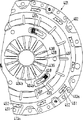
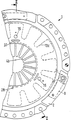
図1は、本発明に従って構成したクラッチ装置の断面図である。
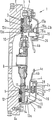
図2は、補償装置の拡大図である。
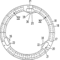
図3は、図2の矢印IIIの方向に見た図である。
図4は、摩擦クラッチのレリーズ手段に接している調整リングの、図2の矢印IVに従う図である。
図5は、図4の線V−Vによる断面図である。
図6は、図1のクラッチ装置に用いられた対向調整リングの、図2の矢印IIIに従う図である。
図7は、図6の線VII−VIIによる断面図である。
図8は、図2に示された補償装置の変化実施例の詳細図である。
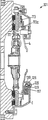
図9は、本発明のクラッチ装置のその他の細部の断面図である。
図10および11は、たとえば図9に従う本発明のクラッチ装置に使用できる摩耗調整リングを示す。
図12は、本発明のクラッチ装置の断面図である。
図12aは、図12に用いられたセンサーばねのセグメントを示す。
図13は、図12の矢印XIIIの方向に見た部分図である。
図14は、本発明の摩擦クラッチのその他の可能な構成を示す。
図15は、本発明のクラッチ装置のためのレリーズシステムの模式図である。
図16は、調整リングのためのブレーキを有する本発明の摩擦クラッチのその他の構成である。
図17は、本発明の摩擦クラッチの図である。
図18は、図17の線II−IIによる断面図である。
図19は、図17および18に従う摩擦クラッチに用いられた調節リングを示す。
図20は、図19の線IV−IVによる断面図である。
図21は、図17および18に従う摩擦クラッチに用いられた支持リングである。
図22は、図21の線VI−VIによる断面図である。
図23および23aは、調節リングに回動力を及ぼすばねを示す。
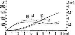
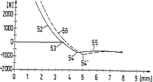
図24〜27は、本発明の摩擦クラッチの個々のばね部材と調整部材との協働を示した種々の特性曲線を記載したグラフである。
図28および29は、本発明の摩擦クラッチのその他の可能な構成を示し、図29は図28の線XIIIによる断面図である。
図30は、図28および29に従う摩擦クラッチに用いられた調節リングの図である。
図31〜33は、補償装置を有するその他の摩擦クラッチの細部を示す。
図34および35は、圧着皿ばねとライニングばねとの協働、およびそれによって発生する摩擦クラッチの解離力特性曲線に対する影響を示した種々の特性曲線を記載したグラフである。
図36は、本発明のその他の摩擦クラッチの部分図である。
図36aは、図36の矢印Aの方向に見た部分図である。
図37は、図36の線XXIによる断面図である。
図38は、図36および37に従う摩擦クラッチに用いられた調節リングの部分図である。
図39および40は、本発明の摩擦クラッチのその他の変化実施例である。
図41は、図28および29または図36および37に従う摩擦クラッチに使用できる調節リングの図である。
図42〜45は、摩擦クラッチの追加の変化実施例を示す。
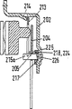
図46〜48は、摩擦クラッチの他の可能な構成の詳細を示し、図47は図46の矢印Aに従う部分図、図48は図47の矢印B−Bに従う断面図である。
図1に示すクラッチ装置は、ケーシング2を備えた摩擦クラッチ1と、このケーシングと回転しないように結合しているが軸方向に限定的に移動できるプレッシャープレート3を有する。軸方向でプレッシャープレート3とカバー2との間に圧着皿ばね4が緊定されており、この圧着皿ばねが、ケーシング2によって支持されたリング状の旋回軸受5を中心にして旋回でき、プレッシャープレート3をケーシング2と固く結合したカウンタープレッシャープレート6、たとえばフライホイールに向かって押し付けており、そうすることによってクラッチディスク8の摩擦ライニング7がプレッシャープレート3とカウンタープレッシャープレート6の摩擦面の間に固定されている。
プレッシャープレート3はケーシング2と周方向もしくは接線方向に向いた板ばね9と回転しないように結合している。図示の実施例では、クラッチディスク8はいわゆるライニングばねセグメント10を有する。このライニングばねセグメントは、2つの摩擦ライニング7の互いに向かう限られた軸方向移動を通して、摩擦ライニング7に作用する軸方向力の漸増的な増加を可能にすることによって、摩擦クラッチ1が接続するときに漸増的なトルク生成を保証する。しかしながら、摩擦ライニング7がサポートディスクに事実上剛に取り付けられているクラッチディスクも用いることができよう。
図示の実施例では、皿ばね4が圧着力を加えるリング状の基体4aを有し、この基体から半径方向内側に操作舌片4bが出ている。この場合、皿ばね4は、さらに半径方向外側に位置する範囲でプレッシャープレート3を押し付け、さらに半径方向内側に位置する範囲で旋回軸受5を傾斜できるように組み込まれている。
旋回軸受5は2つの旋回サポート11、12を包含しており、これらの旋回サポートの間で皿ばね4が軸方向に保持または固定されている。皿ばね4の、プレッシャープレート3に向いた側に設けられている旋回サポート11はケーシング2に向かって軸方向に力を受けている。このために、旋回サポート11は皿ばねもしくは皿ばね状の部材13の一部である。この部材は外側縁範囲13aによりケーシング2に弾性支持されている。そうすることによって、半径方向内側に成形した旋回サポート11が操作皿ばね4に対して、したがってまたケーシング2に向かって軸方向に押し付けられる。プレッシャープレート3と操作皿ばね4との間に軸方向に設けられている皿ばね13は、リング状の範囲13bを有する。その内縁から半径方向内側に延びた舌片13cが出て、旋回サポート11を形成している。
皿ばね状の部材13を支持するために、図示の実施例ではケーシング2と、皿ばね状の部材13の舌片状のブラケット13aとの間に、バヨネット式の結合部材もしくはロック部材が設けられている。
皿ばね状の部材もしくは皿ばね13は、所定の作動行程にわたって少なくともほぼ一定の力を生み出すセンサーばねとして形成されている。このセンサーばね13を通して、舌片先端部4cに作用するクラッチ解離力が少なくともほぼ把捉される。その際に、この解離力によって旋回サポート11に対して生み出される力と、センサー皿ばね13によってこの旋回サポート11に及ぼされる対向力との間には、常に少なくとも近似的な平衡が生じている。ここで解離力とは、摩擦クラッチ1の操作中に舌片先端部4cもしくは皿ばね舌片の解離範囲に及ぼされる最大力を意味する。
ケーシング側の旋回サポート12は、調整装置16を介してケーシング2に支持されている。この調整装置16は、旋回サポート11および12がプレッシャープレート3に向かって、もしくはカウンタープレッシャープレート6に向かって軸方向に移動する際に、旋回サポート12とケーシング2との間、もしくは旋回サポート12と皿ばね4との間に不都合な遊びが生じ得ないことを保証している。そうすることによって、摩擦クラッチ1を操作する際に不都合な死行程もしくは空行程が生じないことが保証される。その結果、最適な効率が、したがって摩擦クラッチ1の申し分ない操作が提供されている。プレッシャープレート3とカウンタープレッシャープレート6の摩擦面および摩擦ライニング7が軸方向に摩耗すると、旋回サポート11および12が軸方向に移動する。
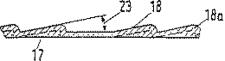
調整装置16は、リング状の部材17として構成されている、ばね作用を受けた調整部材を包含している。この部材は、周方向に延び、かつ軸方向に上昇している、部材17の円周上に分布した乗り上げ傾斜面18を有する。調整部材17は、乗り上げ傾斜面18がケーシング底部2aに向いているように、クラッチ1に組み込まれている。
調整リング17は周方向に、しかも調整回転方向にばね弾性的に負荷されている。この方向は、傾斜面18がカバー底部2aに設けた対向傾斜面19に当たることによって、調整リング17をプレッシャープレート3に向かって、つまり半径方向のケーシング部分2aから離れて軸方向に移動させる方向である。
旋回軸受5もしくは調整部材16の自動調整の機能、ならびに調整部材16のその他の形成可能性を、図17〜48との関連で詳しく設計する。
クラッチ装置は、皿ばね舌片4bによって形成された摩擦クラッチ1のレリーズ手段が軸方向に遊びなく操作され、一定の行程21を移動できることを保証する補償部材20を含んでいる。補償部材20はレリーズベアリングを包含しているレリーズ機構22と、舌片先端部4cとの間に設けられている。レリーズ機構22は模式的に示された、摩擦クラッチ1を操作するためのガイドパイプ23上で軸方向に移動できる。ガイドパイプ23は、詳細に図示されないトランスミッションケーシングに支持されており、クラッチディスク8を回転しないように載せることのできるトランスミッション・インプットシャフトを包囲している。レリーズ機構22の軸方向移動に必要な力は、操作手段24によって加えられる。この操作手段は、図示した実施例では、やはりトランスミッション側で支持できる、模式的に表現したレリーズフォークによって形成されている。しかしながら、油圧または空気圧で作動できるレリーズ機構22、つまり圧力媒体を送り込めるピストン/シリンダーユニットを有するレリーズ機構も使用できる。
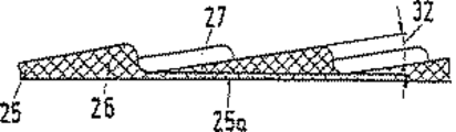
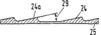
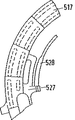
補償装置20が図2および3に拡大して表現されており、図4および5に示されているリング状の部材25として構成された調整部材を包含している。このリング状の調整部材25は、図示された実施例において、半径方向にずらし周方向に延び軸方向に上昇している2組の乗り上げ傾斜面26、27を有する。これらの乗り上げ傾斜面はそれぞれ部材25の円周上に分布している。特に図5から分かるように、半径方向内側の乗り上げ傾斜面26は、半径方向外側に配置された乗り上げ傾斜面27に対して周方向に、傾斜面長さもしくは傾斜面ピッチの約半分だけずれている。図1および2から分かるように、調整部材25は端面25aにより直接舌片先端部4cで支えられている。乗り上げ傾斜面26、27は操作手段4bと軸方向反対側に向いている。調整部材25は周方向に、しかも調整回転方向にばね作用を受けている。この方向は、傾斜面26、27が図6および7に詳細に示された支持リング30の対向傾斜面28、29に当たることによって、調整リング25をプレッシャープレート3に向かって、つまりレリーズ機構22から離れて軸方向に移動させる方向である。
図6および7から分かるように、対向乗り上げ傾斜面28、29も半径方向および周方向に互いにずれた2組の乗り上げ傾斜面を有する。支持リング30の調整部材25および28、29の傾斜面26、27は互いに合わされており、軸方向に互いに係合する。周方向にずれた傾斜面により、調整部材25と支持リング30との間に申し分のない中心案内が存在することが保証される。特に図2から分かるように、補償装置20の2つの部材25および30は軸方向に互いに入り組んでいる。支持リング30の対向乗り上げ傾斜面28、29の設置角31(図7)は、調整部材25の乗り上げ傾斜面26、27の角32(図5)に対応している。支持リング30は、ケーシング2と回転しないように結合しているが、このケーシングに対し軸方向にクラッチ操作行程21だけ限定的に移動できる。この軸方向の制限は、摩擦クラッチ1が接続した状態でカバー底部2aの半径方向内側範囲と当たる、支持リング30の半径方向範囲33を介して行われる。この当たりは、ばね作用を受けた操作手段4bによって引き起こされる。摩擦クラッチ1を解離するとき、行程制限が薄板成形部材34によって保証される。この薄板成形部材は、支持リング30の、操作手段4bと反対側に設けられており、直径範囲35でレリーズ機構22の作用を受ける。この薄板成形部材34も、摩擦クラッチ1を解離したときにカバー底部2aの半径方向内側範囲と当たることができる半径方向範囲36を有する。
図示の実施例では、調整リング25および支持リング30は耐熱プラスチック、たとえばサーモプラストで作られており、さらに繊維強化することができる。こうすることによって、これらの部材は射出成形部材として簡単に作ることができる。
乗り上げ傾斜面26、27および対向乗り上げ傾斜面28、29は、2つの部材25と30の間で少なくとも、摩擦クラッチ1の全寿命にわたって、プレッシャープレート3とカウンタープレッシャープレート6の摩擦面および摩擦ライニング7で発生する摩耗の調整を保証する回動角が可能となるように、周方向に形成されている。この調整角は乗り上げ傾斜面の設計に応じて30゜〜90゜程度であることができる。図示の実施例では、図3に符号37で示したこの回動角は75゜程度である。傾斜面および対向傾斜面の設置角31もしくは32は、6゜〜14゜程度、有利に8゜程度である。この場合、傾斜面および対向傾斜面の実際の角31もしくは32は、これらの傾斜面の半径方向長さにわたって変化する。なぜならば、与えられた回動角に対して同一の高低差が橋渡しされなければならないからである。つまり、傾斜面角31もしくは32は直径が増すに従い小さくなるのである。
部材25の調整に必要な周方向の力作用は、図示された実施例では支持リング30と調整部材25との間に弓形に配置されて緊定された2つのコイルばね38、39で形成された力貯蔵手段によって保証されている。これらのコイルばね38、39は、カバー2と回転しないように固定した支持リング30に支えられており、操作手段もしくは皿ばね舌片4bが摩耗の結果としてカバー底部2aもしくはレリーズ機構22から軸方向に離れると、すぐに調整リング25を回動させる。特に図3および6から分かるように、コイルばね38、39はそれぞれ、周方向に溝状もしくはトーラス状に延びている、リング30のソケット40、41を含んでいる。図2から分かるように、断面が力貯蔵手段38、39の壁に適合されたソケット40は、ばね38もしくは39の断面の円周の半分以上にわたって延びている。その際、図3および6から分かるように、それぞれ1つのスロット状の開口部42、43が支持リング30の操作手段4bに向いた側に、またそれぞれ1つのスロット状の開口部44、45が操作手段4bと反対側にとどまっている。これらのばね38、39は、ソケット40、41を限定する面によって、支持リング30に対して軸方向に確保されている。コイルばね38、39を通すために、扇形ソケット40、41は、それぞれ1つの通し範囲46、47を備えている。この範囲は、少なくともコイルばね38、39の壁の外径に対応する、半径方向の導入幅を有する。この通し範囲46、47を通して、力貯蔵手段38、39を扇形ソケット40、41に斜めに差し込むことができる。まだ弛緩しているコイルばね38、39を扇形ソケット40、41に通した後、調整部材25は支持リング30と組み合わされる。このために、調整リング25に設けられ、同時にコイルばね38、39のための力作用範囲もしくは支持範囲を形成している軸方向ボス48、49は、周方向で通し範囲46、47に接したそれぞれ1つの軸方向スロット範囲50、51に導入される。そうすることによって、力作用範囲48、49は弛緩したコイルばね38、39の一方の端部範囲に位置するようになる。力貯蔵手段38または39の弛緩した位置が図3に示されており、39aで表示されている。コイルばね38、39の他方の端部範囲は、扇形ソケット40、41の、周方向にある底部53、53aに支えられている。調整リング25と支持リング30が回動することによって、ばね38、39を緊張させることができる。通し範囲46、47の角に従う延びよりも大きい所定の相対回動角以後では、調整リング25の力作用範囲48、49がそれぞれスロット44、45の端部範囲に位置するので、乗り上げ傾斜面26、27と対向乗り上げ傾斜面28、29とが接するまで、調整リング25と支持リング30は互いに重なり合って動くことができる。スロット44、45と軸方向ボス48、49は、2つの部材25、30の間に軸方向に作動するスナップ結合部が存在するように互いに合わされている。このために軸方向ボス48、49は、それらの端部範囲に、支持リング30の半径方向に延びている範囲と当たることのできるフック状の部片48aを有する。2つの部材25と30が角37(図3)に対応して追加で相対的に回動することにより、ばね38、39は摩擦クラッチ1の新品状態に対応する緊定された角長54にされる。次に2つの部材25、30を図示されない手段によりこの位置で確保することができる。この手段は、たとえば形状接続を含むことができる。この形状接続は2つの部材25と30の間で働き、カウンタープレッシャープレート6に摩擦クラッチ1を取り付けた後に除くことができ、そうすることによって補償装置20が作動する。特にライニング摩耗を補償するための可能な調整角は、図3に37で示した回動角と対応している。この回動角37以後は、軸方向ボス48、49は、リング25の調整方向にあるスロット44、45の端部範囲と当たる。この位置に対応して緊定されたコイルばね38、39の位置は、図3では38aで示されている。
摩擦クラッチ1の新品状態では、乗り上げ傾斜面と対向傾斜面を形成している軸方向カム26、27および28、29は軸方向に最も離れて係合する。つまり、互いに重なるリング25および30が必要とする軸方向スペースは最も小さい。
図示の実施例では、摩擦クラッチ1の解離方向における操作行程の制限が薄板成形部材34によって保証される。図示されない実施例に従い、たとえばカバー2と協働するこれに必要な衝止範囲を、レリーズ機構22に、しかも摩擦クラッチと一緒に回転する軸受リングまたはこれと結合した部材に設けることもできよう。摩擦クラッチ1の操作行程を軸方向で少なくとも軸心方向の1つに制限することは、ガイドパイプ23に設けられた少なくとも1つの、レリーズ機構22の軸方向ストッパーによって形成することもできよう。
さらに、レリーズ機構22が操作手段4bに直接作用して、対応する補償装置をレリーズ機構22とレリーズ手段24との間に設けることができよう。
摩擦クラッチ1と補償装置20の機能を損ねない張力を、操作手段4bの方向でレリーズ機構22に加えていることが好都合である。
図2〜4から分かるように、調整リング25は半径方向内側のカム55を有する。これらのカムは、回動手段もしくは保持手段のための作用範囲をなしている。この回動手段もしくは保持手段は、必要に応じ他方で回転しないようにケーシング2または支持リング30に当たることができる。このような保持手段は、摩擦クラッチ1もしくは補償装置20を製造し、もしくは組み立てるときに設け、摩擦クラッチ1をフライホイール6に取り付けた後取り除くことができる。
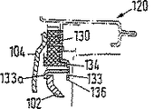
図8に示されている詳細図は、図1および2に示されている補償装置20の下半分の変化実施例を表している。図8に従う変化実施例では、摩擦クラッチが接続した状態で、補償装置120とケーシング102との間の軸方向制限は、薄板成形部材134と一体的に形成されているフック状の軸方向ブラケット133を介して行われる。ブラケット133は、圧縮部材として用いられる薄板成形部材134の外縁に設けられ、軸方向にカバー102を貫通している。ブラケット133は皿ばね104に向いた自由端に、半径方向外側に延びた範囲133aを有する。これらの範囲は、カバー102を皿ばね104に向いた側で半径方向に貫通している。このように形成することによって、皿ばね104から補償装置120に及ぼされる軸方向力を薄板からなる圧縮部材134で支持できることが保証されるので、ストッパーがプラスチック製の支持リング30の範囲33によって形成された、図2に従う補償装置20におけるよりも大きい軸方向力が補償装置120によって吸収できる。補償装置20もしくは120に対するこのような軸方向力は、何よりも輸送時に、つまり摩擦クラッチを取り付けていないときに発生することがある。なぜならばこの状態では主皿ばね4もしくは104は、ばね舌片を介して支持リングもしくはプラスチック補償部材30、130により軸方向に支えられるからである。薄板からなる圧縮部材134は、円周上に好ましくは対称的もしくは均等に分布している2つ以上、なるべくは3つ以上のフック状のブラケット133を有する。圧縮部材134の薄板の厚さは、支持すべき軸方向力に対応して設計できる。プラスチック製リング130は、圧縮部材134と回転しないように結合している。図2と類似に、圧縮部材もしくは薄板成形部材134は半径方向外側に範囲136も有する。これらの範囲は周方向に見れば、フック状のブラケット133の間に延びており、ケーシング102に当たって解離行程を制限し、もしくは許容されない程大きい超過行程を避けるために用いられる。
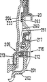
図9に示された摩擦クラッチ201の細部は、本質的に図1に従う摩擦クラッチ1の右下範囲と類似の構造を有する。図9には、クラッチケーシング202、皿ばね204の旋回軸受205、調整装置216および補償装置220が部分的に表現されている。調整装置216と補償装置220の機能に関しては、図1〜8に関する説明、もしくはドイツ特許出願第P4306505.8号および第P4239289.6号を参照されたい。これらの特許出願の内容は明らかに本出願に組み込まれているものと見なすべきである。
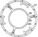
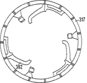
図9に従う変化実施例において、調整リング217として構成された調整部材のための回動防止部材260が設けられている。
移動防止部材もしくは回動防止部材260は、摩擦クラッチ201を取り付けていない状態で、他の部材、たとえば特にケーシング202に対する調整部材217の所定の位置を保証する。特に移動防止部材260によって、摩擦クラッチ201の新品状態で調整部材217をその後退位置、つまりまだ調整が行われていない実用的なゼロ位置に保持できることが保証される。しかもこれは、旋回サポートもしくは支持サポート212の範囲で皿ばね204が調整リング217に作用しないにもかかわらず行われる。このことは、摩擦クラッチ201を取り付けていない状態もしくは摩擦クラッチ201が発送用に準備されている状態で、主皿ばね204がばね舌片を介して補償装置220に軸方向に支持されていることに帰すことができる。これは図1および2との関連でも明らかである。この支持の結果として、主皿ばね204は皿ばね213として構成された力センサーを軸方向でケーシング202もしくは調整リング217から離れる方向に押し付ける。そうすることによって、調整リング217をケーシング202の方向で軸方向に緊定することはもはや保証されていない。したがって、回動防止部材260がなければリング217は移動できるであろう。それゆえ、摩擦クラッチ201を内燃機関の駆動軸に取り付けた状態では、リング217は、特にクラッチディスクの摩擦ライニングに発生する摩耗の調整を保証する所望された後退位置を取らないであろう。図9には、フライホイールに取り付けた摩擦クラッチに対応する部材の位置が実線で表現されている。取り付けていない新しい摩擦クラッチに対応する皿ばね204とセンサーばね213の位置が破線で暗示されている。ここから分かるように、摩擦クラッチ201を取り付けていない状態では、調整部材217もしくはリング状の支持部材212と皿ばね204との間に軸方向間隔もしく隙間がある。
特に摩擦クラッチ201の運搬用に設けられた調整装置216用の調整防止部材260は、少なくとも摩擦クラッチ201を取り付けていない状態で、場合によっては取り付けた摩擦クラッチ201が接続した状態でケーシング202に対して回転不能に保持されており、調整部材217の回転防止のためにこれと協働する、少なくとも1つの止め部材261を有する。止め部材261は、たとえば図10に示されているように、軸方向に延びている個々の若干のアーム262を持つことができる。これらのアームは半径方向外側では調整リング217と固く結合しており、半径方向内側では皿ばね204に向いたケーシング202の側に設けられたストッパー233とケーシング202との間に締め付けることができる。そうすることによって、調整部材217とケーシング202との間に形状接続による結合が与えられている。アーム262は、板ばねに類似して形成され、半径方向内側でリング状の範囲263を介して互いに結合することができる。図示の実施例では、アーム262は調整部材217とねじ止めされているが、アーム262は調整部材217とリベット止めすることもでき、さらには調整部材217と回転不能に結合させるためにこの部材を形成しているプラスチックに埋設された範囲を持つこともできる。
補償装置220もしくはその制限ストッパー233は、ケーシング202および軸方向に締め付け可能な止め部材261の範囲と結合して、摩擦クラッチ201を操作していないときに作動する、調整部材217のためのブレーキもしくはクラッチを形成する。
クラッチを解離すると、止め部材261もしくは帯金262の制動効果もしくは締め付けが解消されるので、調整部材もしくは調整リング217は必要に応じて調整できる。
止め部材261もしくはこれを形成している板ばねに類似した帯金は、軸方向にわずかなばね率もしくはばね強度を有するが、周方向では比較的剛性もしくはばね剛性を有する。
図11に示された調整リング317の実施例において、軸方向に弾力的な帯金362が直接プラスチックリング317に射出成形されている。図10と関連して示されているように、帯金362は類似の仕方で、半径方向内側で円環状の範囲を介して結合できる。
図12および13に表現されているクラッチユニットもしくは摩擦クラッチ401は、薄板カバー402で形成されたケーシング、これと回転しないように結合しているが軸方向で制限されて移動できるプレッシャープレート403、およびこのプレッシャープレート403とカバー402との間に緊定された圧着皿ばね404とを有する。この圧着皿ばね404は、旋回軸受405に傾倒可能もしくは旋回可能に保持されていることによって、ケーシング402に対して2アーム式レバーとして支持されている。皿ばね404は、プレッシャープレート403を、プレッシャープレート403とフライホイールとの間に締め付け可能なクラッチディスク408の摩擦ライニング407に向かって、リング状の旋回軸受405に対して半径方向で一層外側に位置する範囲を押し付ける。プレッシャープレート403とカバー402との間のトルク伝達は、プレッシャープレート403を摩擦ライニング407から持ち上げる方向で緊張させることのできる板ばね409を介して行われる。
皿ばね404はリング状の基体404aと、これから出て半径方向内側に向いている舌片404bとを有する。
旋回軸受405は2つの旋回サポート411、412を包含し、それらの間に皿ばね404が軸方向に保持または締め付けられている。旋回サポート411および412は類似に配置および形成されており、図1に関連して説明した旋回サポート11および12と等しい機能を有する。旋回サポート411、412に作用する部材および旋回軸受405の自動調整機能に関しては、図1および図17〜48の説明を参照されたい。
皿ばね舌片404bによって形成された、摩擦クラッチ401のレリーズ手段は、レリーズ装置422によって軸方向に操作でき、それによって皿ばね404の円錐性が変化できる。レリーズ装置422は、図1〜7との関連で説明したように、補償装置420を有する。しかしながら、自動調整レリーズベアリングを有するクラッチレリーズシステムにおいては、この種類の補償装置420は必要ない。このようなレリーズシステムでは、レリーズ装置422は、少なくとも解離動作の間にクラッチ401と一緒に回転するレリーズベアリングリングと結合していることができる。
皿ばね舌片404bによって形成されたクラッチレリーズ手段の許容されない程大きい解離行程を妨げるために、クラッチ401もしくはケーシング402に皿ばね舌片404bの行程制限手段436が設けられている。行程制限手段436は、皿ばね舌片404bを軸方向に支持し、したがってレリーズ装置420に作用する解離力を軸方向に把捉することによって皿ばね404の旋回行程もしくは旋回角を制限する。
図示された実施例では、行程制限手段436は、カバー402の半径方向内側の部片によって形成されたリング状の衝止範囲436によって形成されている。舌片先端部404cは所定の軸方向行程421の後でこの衝止範囲に当たる。リング状の衝止範囲436は、これが少なくとも皿ばね舌片の解離直径、つまりその上でレリーズ装置422が皿ばね舌片404bに当たる直径上に位置するように形成されている。衝止範囲436は、軸方向でばね舌片404bもしくはばね舌片先端部404cとクラッチディスク408との間に配置されている。
リング状の衝止範囲436は、半径方向に延びたリブもしくはウェブ437を通してカバー基体402aと結合している。図13から分かるように、図示された実施例では、このようなウェブが6つ設けられている。しかしながら若干の応用例に対しては、このようなウェブを3つのみ設けることもできる。特に大きい解離力が必要となるクラッチ仕様においては、より多くのウェブ、たとえば9つのウェブを設けることもできる。
ウェブ437は、カバー底部402bもしくはカバー基体402aから出て半径方向内側に延び、軸方向ではプレッシャープレート403もしくはクラッチディスク408に向かって傾いている。衝止範囲436は、カバー底部402bに対し軸方向でカバースペース内にずれている。ばね舌片404bは、リング状の衝止範囲436と半径方向に一層外側にあるカバー基体402aと結合リブ437との間で形成されている開口部438と係合する。このために、図示の実施例では、皿ばね舌片404bが半径方向内側に全長の一部にわたって、軸方向でウェブ437の延長と反対方向に直角に折り曲げるか、立てられている。図13から分かるように、皿ばね舌片404bは、それぞれ開口部もしくは貫通部438に付属している3体構成をなしている。個々の3体構成の間に、それぞれウェブ437を収容するためのスロット439が設けられている。この場合、スロット439とウェブ437は、皿ばね404の申し分ない旋回が可能となるように互いに合わされている。
皿ばね舌片404bを開口部438に通すことは、摩擦クラッチ401を取り付ける間に行われる。このために、皿ばね404は図12に破線で示された弛緩した状態において、舌片先端部404cの範囲に、リング状の衝止範囲436の外径441よりも大きい内径440を有する。そうすることによって、皿ばね404は、少なくとも完全に弛緩した状態では、皿ばね舌片404bによりカバー402の開口部438に軸方向に挿入できる。摩擦クラッチ401を取り付けている間、もしくは遅くとも摩擦クラッチ401をフライホイールなどに取り付けるときに、皿ばね404が旋回する。そうすることによって、皿ばね舌片404bによって制限された内径440が縮小される。摩擦クラッチをフライホイールに取り付けると、皿ばね404は動作位置を取り、舌片先端部404cは衝止範囲436の外径441より小さい内径442を限定する。旋回行程421を後退した後でも、舌片によって規定される衝止範囲436の内径が外径より小さくなるように、皿ばね404が旋回可能にケーシングに保持され、舌片404aが形成されている。
軸方向に制限された最大可能な操作行程421は、ライニング407で最大許容摩耗に達した後にもクラッチ401が少なくとも申し分のない機能、つまりクラッチ装置401の申し分のない切り離しに必要とされる完全な目標解離行程を有するように設計されている。クラッチ401もしくはクラッチにおける自動ライニング摩耗補償を保証するセンサーばね413および調整装置416は、摩擦クラッチ401の新品状態で旋回軸受405の誤った軸方向移動が行程421を完全に通過した場合でも生じないように、設計されている。
以下に、数値例に基づいて、作動方式もしくは衝止範囲436と皿ばね舌片404bとの協働について説明もしくは実証する。
摩擦クラッチ401の上述の解離行程は、公差の存在を考慮すると8.4〜10mmである。クラッチ401は、新品状態で旋回軸受405の誤った軸方向移動が解離行程14mm以上で初めて可能であるように設計されている。ストッパー436は、摩擦クラッチの新品状態でストッパー436と当たる範囲、すなわち舌片先端部404cが12.5mmの軸方向行程421を通過できるように設計もしくは位置決めされている。皿ばね舌片がストッパー436に当たり、最大解離力を加えると、カバーはさらに約0.5mm軸方向に収縮できるので、合計で13mmの最大軸方向行程421が可能である。
ライニング407で3mmの最大ライニング摩耗が可能であると仮定すると、摩擦クラッチ401の寿命にわたって、皿ばねは、旋回軸受405の軸方向移動によって、この旋回軸受を中心にしてクラッチディスクに向かって3mm移動する。それにより、最大可能解離行程421は約13mmから約10mmに減少するので、クラッチはその寿命の終わりにも依然として要求された解離公差8.4〜10mm以内にある。
図示の実施例では、ストッパー436はカバー402と一体的に構成されている。しかしながら、このストッパーは、カバー402と結合した独立の部材で形成することもできる。ウェブ437も独立の部材で形成するか、または固有の部材として形成されたストッパー436と一体的に構成ができる。
さらに、図12および13に示されたクラッチユニット401は、クラッチユニット401が動作している間、使用中にクラッチユニット401が回転する回転数範囲の少なくとも一部で、皿ばね404に対して軸方向の支持力増加を引き起こす装置もしくは手段を有する。この支持力増加により、クラッチユニット401の操作時に、少なくとも所定の回転数部分で発生する妨害因子の結果として、旋回サポート411と協働する、センサーばね413として構成されたセンサー装置の、ライニング407の摩耗に起因しない、好ましくない軸方向偏向もしくはたわみに基づいて、許容されない調整が行われるのを防止できる。
図12には、転動サポート411に作用する軸方向力を高めるために、回転数もしくは遠心力に依存した手段450が設けられている。遠心力に依存した手段450は、センサー皿ばね413の外側辺縁部に成形され、カバー402に向かって軸方向に設置された舌片450によって形成されている。図12aから分かるように、皿ばね状のセンサーばね413は半径方向外側に延びている舌片状のブラケット413aを有する。これらのブラケットは、図12および13から明らかなように、カバー402に軸方向で支えられている。ブラケット413aと、これを軸方向で支えているカバー402の範囲451との間には、バヨネット式の結合部材もしくはロック部材452が設けられている。バヨネット式の結合部材452は、センサーばね413とケーシング402を軸方向に組み合わせることにより、またそれに続くこれら2つの部材の相対的回動により、ブラケット413aが軸方向にケーシング402の支持範囲451に位置するように構成されている。センサーばね413とカバー402を一緒に組み立てると、これら2つの部材が回動する前に、センサーばね413は最初に弾性的に軸方向に緊張され、回動後に弛緩される。そうすることによって、ブラケット413aは張力によってカバー402に支えられる。図12aから分かるように、半径方向ブラケット413aの両側に舌片450が設けられている。クラッチユニット401が回転すると、遠心力が舌片450に作用する結果として、センサーばね413の張力によって加えられる力に重なる、つまり加算される力が生み出される。そうすることによって、操作皿ばね404に対する支持力は旋回サポート411の範囲で拡大される。旋回サポート411で舌片450によって追加で生み出されるこの力は、回転数が増すにつれて大きくなる。しかしながら、この力の増加は、所定の水準の回転数以後は舌片450が、これに作用する遠心力に基づいて、半径方向外側でケーシング402に支えられるように変形もしくは旋回することによって制限できる。そうすると、遠心力に依存する手段450によって生み出される追加支持力の増加が、旋回サポート411の範囲で生じないか、もしくは事実上生じない。
軸方向の力関係もしくは旋回サポート411と皿ばね404との間の力の平衡を考察する際に、さらに板ばね状のトルク伝達手段409を考慮しなければならない。クラッチユニット401の全寿命にわたってプレッシャープレート403がトルク伝達手段409によって皿ばね404に対し軸方向に力で緊定されているように、この板ばね状のトルク伝達手段409をケーシング402とプレッシャープレート403との間で緊張させることができる。したがって、トルク伝達手段409によって加えられる軸方向力は、皿ばね404からプレッシャープレート403に及ぼされる力に抗して働き、それゆえセンサーばね413によって皿ばね404に加えられる軸方向力と加算される。このとき、これら2つの力は舌片先端部404cに作用する解離力に軸方向で抵抗する。そうすると、クラッチユニット401が回転していないときに皿ばね404の軸方向移動に抵抗する実際のセンサー力は、トルク伝達手段409とセンサーばね413によって生み出され、皿ばね404に作用する合力によって形成される。クラッチユニット401が回転すると、舌片450によって生み出される回転数もしくは遠心力に依存する力がこの合力に重なる。
摩擦クラッチユニット401を操作するとプレッシャープレート403の持ち上げ行程の一部にわたって、クラッチディスク408によって伝達されるトルクの漸次的な解消もしくは漸次的な形成を保証する、たとえばライニングばね453として形成された装置を有するクラッチディスク408において、この舌片450は、プレッシャープレート403が摩擦ライニング407もしくはクラッチディスク408を解離するまでは、調整リング417として構成された調整部材に対する皿ばね404の軸方向支持を保証する。そうすることによって、少なくともほぼ調整リング417の摩擦ライニング407を解離するまでは、軸方向で皿ばね404とケーシングもしくはカバー402との間に緊定され続けており、したがって調整は行われ得ないことが保証される。クラッチユニット401が解離してプレッシャープレート403がライニング407から持ち上がると、舌片450のないクラッチユニットにおいて、板ばね状のトルク伝達手段409とセンサー皿ばね413とによって生み出される合力のみが軸方向の緊定力として主皿ばね404に作用する。この合成センサー力は、舌片404cに導入された解離力に抗して働く。所定の回転数範囲、特に高いエンジン回転数において、たとえばエンジンによって励起された振動が発生してプレッシャープレート403の軸方向振動を引き起こすことがある。プレッシャープレート403が軸方向に振動すると、このプレッシャープレート403は主皿ばねもしくは皿ばね404から短時間持ち上がることがあり、それによって合成センサー力が短時間低下する。なぜならば、このとき板ばね状のトルク伝達手段409によって生み出される軸方向力はもはや皿ばね404には作用しないからである。その結果として、皿ばね404もしくはこの皿ばねに作用する解離力と、この皿ばね404に作用する合成解離力との間で、装置416の計画的な調整に必要な力関係が阻害されている。しかも、このようなクラッチユニット401の動作状態では、皿ばね404に作用する軸方向支持力は小さくなり過ぎるので、クラッチは時期尚早の、もしくは好ましくない調整を行い、それによって皿ばね404の動作点が皿ばね最小限に向かって移動する。さらに、エンジンの所定の動作状態において、特に高いエンジン回転数で、特に大きいクランクシャフト周速が生じることがある。このクランクシャフト周速は調整リング417の慣性に基づいて周速を生み出す。これらの周速は、調整リング417とケーシング402との間で作動する調整ランプ418、419によって、皿ばね404に対する軸方向成分を生み出すことができるが、この軸方向成分は合成センサー力とは反対方向に向けられているので、やはり好ましくない調整が行われることがある。さらに、発生する振動に基づいて乗り上げ傾斜面418、419の間に存在する摩擦係合が減少し、その結果として調整リング417に周方向に作用する調整ばね417aによって生み出されて皿ばね404に作用する軸方向力が増加する。そうすることによって、やはり好ましくない調整が支援される。
遠心力に依存した支持手段450なしでクラッチユニット401の上述の短所を取り除くために、図12〜13に図示した実施例では遠心力に依存した舌片450が設けられている。これらの遠心力に依存した手段450は、センサーばね411によって生み出される力と平行に導入された、回転数もしくは遠心力に依存して増加する支持力を生み出すことによって、回転数に依存する妨害効果を補償する。
この場合、クラッチユニット401におけるライニング摩耗に必要な調整がクラッチユニット401の停止時または少ない回転数で可能であるように、遠心力に依存する手段を構成できる。そうすると、回転しているクラッチユニット401もしくは臨界的振動が発生し得る回転数以上では、調整装置416を事実上ロックできる。
図14に示されている摩擦クラッチ501の実施例では、センサーばね513が、皿ばね旋回軸受505の半径方向内部に配置されている。センサーばね513はリング状の基体513aを有し、ここから半径方向内側に向いた舌片513bが出ている。これらの舌片513bを通して、センサーばね513はリング状の衝止範囲536に支えられている。この衝止範囲は、図12および13に従うリング状の衝止範囲436のように、配置および構成されている。センサー舌片513bは、衝止範囲536の、皿ばね舌片先端部504cに向いた側に支えられている。基体513aは半径方向外側にも舌片513cを有する。これらの舌片は皿ばね504を軸方向で支持するためにこれと当たっている。
センサーばね513のカバー502への取り付けは、内側舌片513bに制限された内径540が衝止範囲536の外径541より大きくなるまで、このセンサーばねが円錐状に変形されることによって行うことができる。こうすることによって、支持舌片513bは、図12および13の舌片404bおよび開口部438との関連で説明したのと類似の仕方で、カバー502の開口部538に挿入できる。舌片513bが開口部538に挿入された後、センサーばね513は弛緩できる。そうすることによって、舌片513bの内側端部範囲はより小さい直径に移動され、衝止範囲536に当たる。
もう1つの可能性は、センサーばね513をカバー502に取り付けるために、少なくとも内側舌片513bの一部が軸方向にカバー502に向かって持ち上げられて、衝止範囲536の外径よりも大きい内径540を限定することである。センサーばねもしくは舌片513bがカバーの開口部538に挿入された後、舌片513bの半径方向内側の範囲が張力により衝止範囲536に当たるようにこの舌片を曲げ戻すことができる。この曲げ戻しによって、舌片513bは皿ばね材料の塑性変形により図14に示されている破線の位置から、実線で示された位置に旋回する。センサー舌片513bを塑性変形させるために、これらのセンサー舌片は皿ばね504の舌片504bもしくは舌片先端部504cに軸方向で支持されることができる。舌片513bの曲げ操作のために、操作皿ばね504の舌片504bを上方から支持し、センサーばね舌片513bに下方から、しかも舌片513bが折り曲げられている直径範囲で作用する工具を用いることができる。
皿ばね404および504の解離行程もしくは旋回角を制限するストッパー436および536の長所は、これらが対応するクラッチ401もしくは501に組み込まれており、皿ばね舌片404bもしくは504bの範囲で作動する点である。そうすることによって、皿ばね舌片404b、504bがストッパー436、536に当たると、皿ばね舌片は軸方向に変形できないか、わずかしか変形できないことを保証できる。そうすることによって、摩擦クラッチ401、501が解離した状態に対応する位置で、皿ばね舌片404b、504b自体はクラッチディスク408の部材に当たらないことを保証できる。図12には、解離したクラッチに対応する皿ばね404の位置が破線で示され450で表示されている。つまりそれによって、摩擦クラッチ401が解離した状態で、このクラッチ401に対して回転しているクラッチディスク408に皿ばね舌片404bが当たったり、滑ったりすることを避けることができる。
図12〜14に従う図示の実施例では、ストッパー436、536が皿ばね舌片先端部404c、504cの範囲で設けられている。しかしながら、これらのストッパーは別様に構成して、内側の舌片先端部404c、504cに対して半径方向外側にずれているようにすることもできる。しかしながら、このような構成においては、皿ばね舌片404b、504bがこれらに作用する解離力とストッパーによる支持のために許容されない程たわむことがないように、舌片先端部404c、504cと半径方向に一層外側に位置するストッパーとの間にある半径方向レバーアームが選択されていることが好都合である。
上述の過大な、もしくは許容されない大きい解離行程は、図示および説明した構成において皿ばね舌片によって形成されているクラッチ操作手段に作用するレリーズシステムもしくは操作システムによって引き起こされることがある。この操作システムは、通常摩擦クラッチの操作手段に作用するレリーズベアリング、クラッチペダルなどの操作部材およびレリーズベアリングと操作部材との間に設けられている力伝達系統を包含している。この力伝達系統はインプットシリンダーとアウトプットシリンダーを有することができる。インプットシリンダーとアウトプットシリンダーとを有するレリーズシステムにおいて、正常な解離行程を越えた許容されない解離行程は、摩擦クラッチがすばやく接続し再び解離する結果、アウトプットシリンダーが十分速く復帰できないことによって起こることがある。つまり、アウトプットシリンダーが最終位置に達しないので、その直後に行われる再解離ではアウトプットシリンダー自体は正常な解離行程に対応する行程を通過するが、正常な解離行程と実行されない残余復帰行程との合計に対応するクラッチの全解離行程が生じる。そうすることによって、クラッチの所定の最大所要解離行程を著しく越える摩擦クラッチの全操作行程が生じ得る。つまり、摩擦クラッチで設けられている操作のための予備超過行程も越えるのである。
本発明の方策もしくはストッパー36、436、536により、摩擦クラッチを操作するときに許容されない程大きい解離行程もしくは超過行程を防止できるが、クラッチの寿命にわたって必要な所定の正常解離行程が保証されている。
したがって本発明に従い、まったく一般的にクラッチにおいて、特に少なくともクラッチディスクの摩擦ライニングの摩耗を保証する調整装置を有するクラッチにおいて、クラッチ操作手段を操作するときにこのクラッチ操作手段の超過行程を避ける、少なくとも1つのストッパーをクラッチ操作系統に設けることができる。このようなストッパーは、たとえばレリーズベアリングの解離行程または皿ばねの旋回行程を制限できる。しかしながら、このようなストッパーは、別の箇所に設けることもできる。さらに、解離方向においても、接続方向においても、ストッパーなど所定の制限部材を設けることによって、摩擦クラッチの操作行程を所定の一定値に制限できる。
このような制限がレリーズベアリングの範囲で起こり得ることが好都合である。なぜならば、この範囲では摩擦クラッチの皿ばね舌片などの操作手段と所定の行程を制限している部材との間の公差連鎖は小さいからである。
このような制限部材もしくはこのようなストッパーがあると、解離の際に事実上剛な制限部材に衝突するので、部材、特にレリーズシステムの部材の過負荷がかかったり、あるいはフット操作式システムでは操作者にとっても好ましくないこともある。それゆえ、本発明の構成に従い、摩擦クラッチの操作系統に、ばね弾性的もしくは弾力的なたわみ手段および/またはレリーズシステムにおける圧力を制限する手段が設けられる。その際、この手段は、クラッチの操作に必要な最大力もしくは必要な最大圧力より少なくともやや大きい張力を有するか、最小変形力もしくは開放力を必要とする。それによって、ストッパーが作動するときにクラッチペダルをさらに踏み込めること、もしくは操作モータが所定の位置まで動作できることが保証される。摩擦クラッチの操作系統に設けられているたわみ手段は、クラッチ操作手段とレリーズベアリングとの間、またはレリーズベアリングと解離操作手段、たとえばクラッチペダルまたはレリーズモーターとの間に設けることができる。
図15には、レリーズシステム601が図示されているが、ここにはレリーズベアリング622がクラッチ操作手段604および/またはクラッチケーシング602に及ぼし得る最大力を制限するための手段の配置構成の種々の可能性が示されている。図15には、図1および2に従うストッパー36との関連で説明したのと類似に、レリーズベアリング622の所定の行程の後にケーシング602に当たる軸方向ストッパー636が設けられている。しかしながら、この解離行程制限は、たとえば図12〜14に関連して説明したように、別の仕方でも行うことができよう。レリーズシステム601は管652を通して連結されたインプットシリンダー650とアウトプットシリンダー651とを有する。アウトプットシリンダー651のピストン653はレリーズベアリング622を支持しており、ケーシング654に軸方向に移動可能に収容されている。圧力室655には管652を通して油などの液圧媒体が供給される。シリンダーユニット650は、中に設けられたピストン657と連結して容積が可変な圧力室658を形成するケーシング656を有する。圧力室658は管652を通して圧力室655と連結している。圧力室658には、ピストン657のための戻しばね659が設けられている。ピストン657は、クラッチペダルや操作モーター、たとえば電動モータまたはポンプを介して軸方向に移動できる。レリーズシステム601の圧力媒体回路は、圧力媒体容器660と連結している。インプットシリンダー650が管661を通して圧力媒体容器660と直結していることが好ましい。
解離手段604および/またはケーシング602に作用するクラッチ操作力を制限するために、図15に従う実施例では、レリーズシステム601の圧力媒体循環に、摩擦クラッチを操作したときに圧力媒体循環内に発生する圧力を所定の値に制限する、少なくとも1つの手段が設けられている。図15に従う実施例では、この手段は少なくとも1つの圧力制限弁によって形成されている。図15には、このような圧力制限弁の種々の配置構成の可能性が示されている。このような圧力制限弁662は、たとえば配管系652内に設けることができ、圧力媒体容器660内への還流路663を有する。しかしながら、圧力制限弁662の代わりに、圧力制限弁664を設けることもできる。この圧力制限弁歯面、ケーシング654によって支持され、またはこのケーシングに完全に組み込むことができ、圧力室655と連通しており、還流管665を通して圧力媒体容器660と連結している。
図15には、圧力制限弁666の配置構成の別の可能性が示されている。圧力制限弁666はインプットシリンダーの圧力室658と連結しており、ケーシング656によって支持され、またはこのケーシングに組み込むことができる。さらに、この圧力制限弁666は、圧力媒体タンク660へ還流するようになっている。このために圧力制限弁666は固有の管を有するか、管661と連結している。
圧力制限弁667を配置するもう1つの可能性は、これをインプットシリンダー650のピストン657に組み込むことである。この弁667は弛緩側で圧力媒体容器660または少なくとも中間貯蔵容器と連結している。
逃がし弁の代わりに、レリーズシステム内に発生する最大圧力を制限する圧力媒体循環内に油圧貯蔵器を設けることもできる。この油圧貯蔵器は、圧力媒体の貯蔵によって解離行程を制限するためのストッパーが行動した後にシステムを弛緩させ、したがって事実上緩衝装置もしくはばね力貯蔵手段として働くことによって、レリーズシステム内に発生する最大圧力を制限する。
図16に示されたクラッチユニット701は、上掲の図に関連して説明したのと類似に、クラッチディスク708の摩擦ライニング707で生じる摩耗を自動的に補償するための調整装置716を有する。図示の実施例では、基本的な構造と調整装置716の作動方式は、図12および13のそれに対応している。調整部材もしくは調整リング717は、クラッチユニット701の解離動作中に皿ばね704と協働できる接触範囲もしくは衝止範囲770を有する。解離動作中に皿ばね範囲771が、調整リング717に支持された衝止範囲770に少なくとも間接的に、なるべくは直接的に、軸方向に支持されるように、衝止範囲770はこれと協働する皿ばね704の範囲771を基準に軸方向に相対的に配置されている。この相互的支持が、舌片先端部704cの範囲で目標解離行程772もしくは対応する皿ばね404の旋回角に少なくともほぼ達するか、もしくはわずかに越えるたときに行われるようにされているのが好都合である。誤った、もしくは不適切に調整されたレリーズシステムが原因で、目標解離行程772cをわずかに越えることがある。皿ばね704を接触範囲770で軸方向に支えることによって、調整リング717の好ましくない回動が防止される。つまり、皿ばね704は所定の解離行程772を越えるときに、事実上調整リング717のブレーキとして働くのである。
図示された実施例において、接触範囲もしくは衝止範囲770は旋回軸受705の半径方向外部でリング717に成形されているリング状の突出部773によって形成されている。リング状の半径方向突出部の代わりに、円周上に分布した若干の半径方向ブラケット773が、図示の実施例では皿ばね704の外縁まで延びている。所定の解離行程772に達するとすぐに、皿ばね704が外側範囲771により調整リング717の衝止範囲770に支えられている。所定の解離行程772を越えると、皿ばね704の旋回直径は拡大する。なぜならば、この旋回直径は、旋回軸受705の直径から、皿ばね704の範囲711と衝止範囲770との間の接触直径に移行するからである。この移行により、舌片先端部704cの範囲で必要な解離力の減少も行われる。なぜならば、皿ばねのてこ比はiからi+1に変化するからである。しかも、最初に解離行程772までは2アームレバーとして支持されている皿ばねが、行程772を越えると事実上1アームレバーとして旋回するからである。この解離力減少によって、皿ばね704が特にセンサーばね713と板ばね709によって加えられる軸方向の合成支持力もしくは作用力によりケーシング702もしくは調整リング717に向かって圧迫されることも保証される。したがって、皿ばね704は全体が調整リング717もしくはカバー702から軸方向に離れて移動できない。所定の解離行程772を越えると、センサーばね713は軸方向にばね弾性的に変形する。しかも、それは皿ばねがこのとき旋回軸受705の範囲で調整リング717から持ち上げられるからである。
突出部もしくはブラケット773が、プラスチックから作られた調整リング770に射出成形されていることが好都合である。ブラケット773に軸方向に作用する最大力は、皿ばね舌片704cの範囲の最小解離力と、センサーばね713および板ばね部材709によって加えられる皿ばね704に対する軸方向のセンサー力もしくは支持力との差から生じる。ブラケット773は、この最大力に重大な変形なしに耐えられるように形成されている。
別の重要な長所は、プレッシャープレート703の軸方向の持ち上げが事実上一定にとどまり、したがって行程772を越えると板ばね709によって主皿ばね704に加えられる軸方向力はそれ以上低下しないことにある。板ばね709によって加えられる力は、合成センサー力の一部をなしているので、この板ばねの残っている残留張力に基づいて摩擦クラッチ701の超過行程安定性が増大する。それによって、たとえば乗用車のクラッチは、調整装置716の機能を損ねることなく、舌片先端部704cの範囲で約0.5〜2mmの超過行程を実現できる。
プレッシャープレート703の持ち上げ制限は、所定の解離行程を越えると、プレッシャープレート703がセンサーばね713に軸方向に支持されることによっても行うことができる。このためにセンサーばね713および/またはプレッシャープレート703に、カムや突起などの成形部材を設けることができる。
図17および18に示された摩擦クラッチ1は、ケーシング2、およびこのケーシングと回動不能に結合しているが、軸方向に限定的に移動可能なプレッシャープレート3を有する。プレッシャープレート3とカバー2との間には軸方向に圧着皿ばね4が緊定されている。この圧着皿ばねはケーシング2に支持されたリング状の旋回軸受5を中心にして旋回可能であり、プレッシャープレート3をケーシング2と固着したカウンタープレッシャープレート6、たとえばフライホイールに向かって押し付ける。そうすることによって、クラッチディスク8の摩擦ライニング7はプレッシャープレート3とカウンタープレッシャープレート6の摩擦面の間に締め付けられる。
プレッシャープレート3は、周方向もしくは接線方向に向いた板ばね9を介してケーシング2と回動不能に結合している。図示された実施例では、クラッチディスク8はいわゆるライニングばねセグメント10を有する。これらのライニングばねセグメントは、2つの摩擦ライニング7が互いに向かって軸方向に限定的に移動することを通して摩擦ライニング7に作用する軸方向力の累進的な増加を可能にすることによって、摩擦クラッチ1を接続したときに累進的なトルク生成を保証する。しかしながら、摩擦ライニング7が軸方向に事実上剛にサポートディスクに取り付けられているようなクラッチディスクも使用できるであろう。このような場合、「ライニングばねパッケージ」、つまり皿ばねと組み合わせたスプリング、たとえばカバーとフライホイール、カバーとカバー側サポートおよび皿ばねとプレッシャープレートとの間、またはカバー弾性によるスプリングを使用できるであろう。
図示された実施例では、皿ばね4は圧着力を加えるリング状の基体4aを有し、この基体から半径方向内側に向かって延びている操作舌片4bが出ている。この場合、皿ばね4は、半径方向一層外側に位置する範囲がプレッシャープレート3を押し付け、半径方向一層内側に位置する範囲が旋回軸受5を中心にして傾倒可能であるように組み込まれている。旋回軸受5は2つの旋回サポート11、12を包含している。これらの旋回サポートはワイヤーリングによって形成され、これらの旋回サポートの間で皿ばね4が軸方向に保持もしくは締め付けられている。皿ばね4の、プレッシャープレート3に向いた側に設けられている旋回サポート11は、力貯蔵手段13により軸方向にケーシング2に向かって押し付けられている。力貯蔵手段13は、皿ばねもしくは皿ばね状の部材13によって形成されている。この部材は、外側縁範囲13aがケーシング2に支持されており、半径方向一層内側の部片により、旋回サポート11を操作皿ばね4に対して、したがってまたケーシング2に向かって軸方向に押し付けている。プレッシャープレート3と操作皿ばね4との間に設けられている皿ばね13は、リング状の外側縁部13bを有する。その内縁から半径方向内側に延びている、旋回サポート11に支えられた舌片13cが出ている。
皿ばね状の部材13を支持するために、図示の実施例ではケーシング2に、皿ばね状の部材13のための旋回サポートを形成する追加の手段14が固定されている。これらの追加の手段は、ピン止めまたはリベット止めされて円周上に均等に分布できる、セグメント状の単独部材14によって形成できる。さらに、支持手段14は、たとえばケーシング2の軸方向範囲に設けたエンボス加工部または舌片状の部片によって直接ケーシング2から型出しできる。これらの部片は、皿ばね状の部材13を挿入し緊定した後に、材料変形によってこの部材13の外縁範囲に押し込まれる。さらに、支持部材14と皿ばね状の部材13との間に、バヨネット式の結合部材もしくはロック部材が設けられているので、皿ばね状部材13を最初に緊張させ、その半径方向外側の範囲を軸方向に支持手段14の上に置くことができる。その後で、皿ばね状の部材13をケーシング2に対して対応して回動させることにより、部材13の支持範囲を支持手段14と接触させることができる。その際、皿ばね状の部材13はリング状の基体13bから半径方向外側に向かって突き出しているブラケットによって形成できる。
操作皿ばね4、場合により皿ばね状の部材13の回動を防止するため、またワイヤーリング11、12の心出しのために、リベット部材15として形成された、軸方向に延びている心出し手段がケーシング2に固定されている。これらのリベット部材15はそれぞれ軸方向に延びているシャフト15aを有する。このシャフトは、隣り合う皿ばね舌片4bの間に設けられた部片を通って軸方向に延びており、これに付属している、皿ばね13の舌片13cに成形されている範囲13dによって一部包囲できる。
皿ばね状の部材もしくは皿ばね13は、所定の作動行程にわたって少なくともほぼ一定の力を生み出すセンサーばねとして形成されている。このセンサーばね13を通して、舌片先端部4cに加えられるクラッチ解離力が把捉される。その際に、この解離力によって旋回サポート11に対して生み出される力と、センサー皿ばね13によってこの旋回サポート11に及ぼされる対向力との間には、常に少なくとも近似的な平衡が生じている。ここで解離力とは、摩擦クラッチ1の操作中に舌片先端部4cもしくは皿ばね舌片のレリーズレバーに及ぼされる、したがってセンサーばね13に抗して働く力を意味する。
ケーシング側の旋回サポート12は、皿ばね4とケーシング2との間の軸方向スペースに設けられた調整装置16を介してケーシング2に支持されている。この調整装置16は、旋回サポート11および12がプレッシャープレート3に向かって、もしくはカウンタープレッシャープレート6に向かって軸方向に移動するときに、旋回サポート12とケーシング2との間、もしくは旋回サポート12と皿ばね4との間に不都合な遊びが生じ得ないことを保証している。そうすることによって、摩擦クラッチ1を操作する際に不都合な死行程もしくは空行程が生じないことが保証される。その結果として、最適な効率、したがって摩擦クラッチ1の申し分ない操作が提供されている。プレッシャープレート3とカウンタープレッシャープレート6の摩擦面および摩擦ライニング7が軸方向に摩耗すると、旋回サポート11および12が軸方向に移動する。しかし、本発明に従う装置においてこの調整は、旋回サポート11、12、これと軸方向に向き合う皿ばねの範囲で摩耗した場合、およびプレッシャープレートサポート(3a)の範囲あるいはこれと向き合う皿ばねの範囲で皿ばねが摩耗した場合にも行われる。旋回軸受5の自動調整を図24〜27に従うグラフに関連して詳細に説明する。
調整装置16は、図19および20に示す、リング状の部材17として構成されてばね作用を受けた調整部材を包含している。このリング状の部材17は、周方向に延び、かつ軸方向に上昇している、部材17の円周上に分布している乗り上げ傾斜面18を有する。調整部材17は、乗り上げ傾斜面18がケーシング底部2aに向いているようにクラッチ1に組み込まれている。調整部材17の、乗り上げ傾斜面18とは反対側に、ワイヤーリングによって形成された旋回サポート12が溝状のソケット19(図18)に心出しされている。ソケット19は、旋回サポート12が調整部材17において軸方向にも確保されているように形成されている。これはたちえば、少なくとも部分的にソケット19に隣接する調整部材17の範囲が、旋回サポート12を締め付けて保持するか、旋回サポート12のためのスナップ結合部材を形成することによって行うことができる。旋回サポート12および調整部材17に異なる材料を使用するときは、大きい温度変化において発生する膨張差を補償するために、ワイヤーリングとして設計された旋回軸受12が開いていること、つまり円周が少なくとも1カ所で切り離されていることが好都合であろう。そうすることによって、ワイヤーリング12がソケット19に対して周方向に移動することができ、したがってワイヤーリング12はソケット19の直径変化に適合できる。
図示の実施例では、調整部材17はプラスチック、たとえば耐熱サーモプラストで作り、さらに繊維強化することができる。こうすることによって、調整部材17はこれらの射出成形部材として簡単に作ることができる。比重の小さいプラスチック製調整部材は、上述のようにより小さい慣性重量を生むが、それによって圧力振動に対する感度も減少する。旋回サポートも、直接プラスチックリングで作れるであろう。しかしながら、調整部材17は薄板成形部材として、または焼結によって作ることもできる。さらに、材料を対応して選択すれば、旋回サポート12を調整部材17と一体的に形成できる。旋回サポート11は直接センサーばね13によって形成できる。このために、舌片13cの先端部は、対応するエンボス加工部もしくは成形部、たとえば溝を備えている。
調整リング17は、円周上に均等に分布しているリベット15の、軸方向に延びている範囲15aによって心出しされる。このために、調整リング17は、旋回サポート11の半径方向内部に位置した、周方向に延びている貫通部21によって形成された心出し輪郭20を有する。これらの貫通部21を形成するために、調整リング17は内縁範囲に半径方向内側に延びたカム22を有する。これらのカムは貫通部21の半径方向内側に輪郭を限定している。
図19から分かるように、周方向に見て、均等に分布した貫通部21の間にそれぞれ5つの乗り上げ傾斜面18が設けられている。これらの貫通部21は、摩擦クラッチ1の全寿命にわたって、プレッシャープレート3とカウンタープレッシャープレート6の摩擦面および摩擦ライニング7で発生する摩耗、さらに場合によりクラッチそのものの、つまりたとえばサポート11、12、その間にある皿ばね範囲、プレッシャープレートカム(3a)またはこれと向き合う皿ばね4の範囲の摩耗の調整を保証する、ケーシング2に対する調整リング17の回動角が可能となるように、周方向に形成されている。この調整角は乗り上げ傾斜面の設計に応じて8゜〜60゜程度、なるべくは10゜〜30゜程度であることができる。図示の実施例では、この回動角は12゜程度であり、乗り上げ傾斜面18の設置角23も12゜の範囲にある。この角度23は、調整リング17の乗り上げ傾斜面18と、図21および22に示された支持リング25の対向乗り上げ傾斜面24とを互いに押し付けると発生する摩擦が、乗り上げ傾斜面18と24との間で滑りを防ぐように選択されている。乗り上げ傾斜面18および対向乗り上げ傾斜面24の範囲における材料の組み合わせに応じ、角度23は4゜〜20゜の範囲にあることができる。
調整リング17は、周方向に、しかも調整回転方向にばね弾性的に負荷されている。この方向は、傾斜面18が支持リング25の対向傾斜面24に当たることによって、調整リング17をプレッシャープレート3に向かって、つまり半径方向のケーシング部分2aから離れて軸方向に移動させる方向である。図17および18に示された実施例では、調整リング17のばね弾性が、少なくとも1つのリング状の脚ばね26に保証されている。この脚ばねは、たとえば2つのコイルを持つことができる、その一方の端部に半径方向に延びて調整リング17と回動不能になっている脚部27、他方の端部に軸方向に延びてケーシング2と回動不能になっている脚部28を有する。ばね26は、ばね弾性によって緊張させて取り付けられている。
図21および22に示されている支持リング25も、リング状の部材によって形成されている。この部材は、乗り上げ傾斜面18によって限定された面を補完する面をなしている対向乗り上げ傾斜面24を有する。この場合、乗り上げ傾斜面18および対向傾斜面24によって限定された面は、合同であることもできる。対向傾斜面24の設置角29は、乗り上げ傾斜面18の角度23に対応している。図19と21を比較すると分かるように、乗り上げ傾斜面18と対向乗り上げ傾斜面24は周方向に類似して分布している。この支持リング25は、ケーシング2と回動不能に結合している。このために、支持リング25は円周上に分布している貫通部30を有しており、これらの貫通部を通してリベット15のリベット端部が貫通している。
図18にもう1つのリング状の脚ばね26aが破線で暗示されている。この脚ばねは脚ばね26と類似に端部範囲を持ち上げて、一方ではケーシング2と、他方では調整部材17と回動不能に結合することを保証できる。このばね26aもばね弾性的に緊張させて取り付けることができるので、調整部材17に回動力を及ぼす。2つの脚ばね26、26aを用いることは、若干の応用例にとって好都合であり得る。なぜならば、摩擦クラッチ1が回転すると、ばね26もしくは26aに作用する遠心力に基づいてばね力が増加するからである。2つの脚ばねを使用することにより、たとえばばね26で発生する力の増加を脚ばね26aによって加えられる力によって補償できる。このために脚ばね26および26aは、少なくとも遠心力の影響で調整部材17に、円周方向に反対に働く力を生み出すように巻かれている。2つの脚ばね26、26aは1つ以上のコイルを持っている。さらに、図18に示されているように、これらの脚ばね26、26aのコイル直径は異なっている。その際、通常コイルと組み合わせてばね26、26aに作用して、調整部材17に種々の大きさの周方向力を生み出すであろう遠心力は、ワイヤの太さおよび/または個々のばね26、26aのコイル数を対応して設計することにより、少なくともほぼ補償することができる。図18には、ばね26が調整部材17の半径方向内部に、またばね26aがこの調整部材17の半径方向外部に配置されている。しかしながら、2つのばねは、対応した設計により、調整部材17の半径方向内部または半径方向外部にも配置できるであろう。
図23に、脚ばね26の平面図を示す。脚ばね26が弛緩した状態では、脚27、28は角度31だけ変位している。この角度は40゜〜120゜程度であることができる。図示の実施例では、この角度31は85゜程度である。32は、脚28に対する脚27の相対的な位置を表している。この位置は、新しい摩擦ライニング7では摩擦クラッチ1内にある。33は、摩擦ライニング7の最大許容摩耗に対応する脚27の位置を表している。図示の実施例では、調整角34は12゜程度である。ばね26は、このばね26が弛緩した状態で2つの脚27、28の間に1つのワイヤーコイル35のみが延びているように形成されている。残りの円周範囲では、2つのワイヤーコイルが軸方向に上下に重なっている。ばね26aはばね26と類似に形成されているが、コイル直径は大きく、図18に従い調整部材17を基準にして別の緊定方向を有する。しかしながら、ばね26により調整リング17に及ぼされる力は、ばね26aの力より大きい。
摩擦クラッチ1の新品状態では、乗り上げ傾斜面18と対向傾斜面24を形成している軸方向カム18a、24aは軸方向に最も離れて係合している。これは、互いに重なるリング17および25は最も小さい軸方向スペースを必要とすることを意味する。
図17および18に従う実施例では、対向乗り上げ傾斜面24もしくはこれを形成しているカム状の突起24aは、固有の部材によって形成されている。しかしながら、対向乗り上げ傾斜面24は、直接ケーシング2によって、たとえばケーシング空間内に延びることのできるエンボス加工部やカム状の突起によって形成することができる。エンボス加工品は、特に一体的に形成されている薄板製のケーシングもしくはカバーにおいて好都合である。
摩擦クラッチ1を取り付ける前に調節リング17を後退した位置で保持するために、この調節リングはカム22の範囲で回動手段もしくは保持手段のための作用範囲36を有する。この回動手段もしくは保持手段は、他側でケーシング2で支えることができる。このような保持手段は、摩擦クラッチ1を組み立てるときに設け、摩擦クラッチ1をフライホイール6に取り付けた後にクラッチから取り外すことができ、そうすることによって調整装置16が作動する。図示の実施例では、このためにカバーもしくはケーシング2に円周方向に付けた細長い貫通部37が、また調整リング17には凹部もしくは突起38が設けられている。この場合、円周方向に設けた細長い貫通部37は、少なくとも調整リング17が最大可能な摩耗調整角に対応し回し戻すことができるほどの長さがなければならない。摩擦クラッチ1を組み立てた後も、回動工具を軸方向にカバーのスロット37に通し、調節リング17の貫通部38に導くことができる。その後でリング17は工具を使って回し戻すことができるので、リング17はケーシング2の半径方向範囲2aに向かって移動し、この範囲2aに対して最小の軸方向間隔を取る。次にこの位置で調整リング17が、たとえばクランブまたはピンによって確保される。ピンはカバーおよび調整リング17と同一平面の貫通部に貫入し、これら2つの部材の回動を防ぐ。このピンは、摩擦クラッチ1をフライホイール6に取り付けた後は、貫通部から取り外すことができるので、上述のように、調整装置16を解離できる。ケーシング2内のスロット37は、摩擦クラッチ1をフライホイール6から取り外すとき、もしくは取り外した後に、調整リング17がその後退位置に入れるように形成されている。このために最初にクラッチ1が解離されるので、操作皿ばね4は旋回サポート12に軸方向力を及ぼさず、したがって調整リング17の申し分ない回動が保証されている。
内燃機関にすでに固定された摩擦クラッチ1の部材を適正に機能する位置に置くもう1つの可能性は、調整部材もしくは調整リング17を、内燃機関もしくは内燃機関のフライホイールに取り付けた後に回し戻すか、後退させることである。このために、たとえば補償工具を通して摩擦クラッチ1を操作し、次に事実上弛緩したリング17をプレッシャープレートに対して後退した位置に入れることができる。その後で、摩擦クラッチ1は再び接続されるので、リング17はこの後退した位置をさしあたり維持する。
リング状の調整部材17もしくは支持リング25は、半径方向で変位して周方向に延び、軸方向に持ち上がっている、それぞれ2組の乗り上げ傾斜面を有する。これらの傾斜面は、それぞれこれらの部材の円周上に分布している。その際、半径方向内側の乗り上げ傾斜面は、半径方向外側に配置されている乗り上げ傾斜面に対して周方向に、傾斜面長さもしくは傾斜面ピッチの約半分だけ変位して配置できる。周方向に変位した傾斜面によって、調整部材17と支持リング25との間の申し分ない中心案内が実現される。
以下に、図24〜27に従うグラフに記入した特性曲線との関連で、上述の摩擦クラッチ1の機能を詳細に説明する。
図24の線40は、皿ばね4の円錐性の変化に依存して、しかも2つの支持部材の間で皿ばね4が変形するときに生み出される軸方向力を示す。これらの支持部材の半径方向間隔は、旋回軸受5と、プレッシャープレート3における半径方向外側の支持直径3aとの間の半径方向間隔に対応している。横座標には2つのサポートの間の相対的軸方向行程が、縦座標には皿ばねによって生み出された力が示されている。点41は、好ましくは閉じたクラッチ1で皿ばね4の取り付け位置として選択される皿ばねの平面位置、つまり皿ばね4が対応する取り付け位置に対して最大圧着力をプレッシャープレート3に及ぼす位置を表している。点41は、皿ばね4の円錐取り付け位置、つまり設置の変化によって、線40に沿って上方または下方に移動できる。
線42は、ライニングばねセグメント10に加えられ、2つの摩擦ライニング7の間に作用する軸方向の突っ張り力を表す。この軸方向の突っ張り力は、皿ばね4からプレッシャープレート3に及ぼされる軸方向力に抗して作用する。ばねセグメント10の可能な弾性変形に必要な軸方向力は、少なくとも皿ばね4によってプレッシャープレート3に及ぼされる力に対応していることが好都合である。摩擦クラッチ1が解離すると、ばねセグメント10は行程43にわたって弛緩する。プレッシャープレート3の対応する軸方向移動にも対応するこの行程43にわたって、クラッチ1の解離動作が支援される。つまり、ライニングばねセグメント10がない場合(ライニングばね弾性がない場合)に取り付け点41に対応するであろう解離力よりも小さい最大解離力を加えればよい。点44を越えると、摩擦ライニング7が解離され、皿ばね4の漸減的な特性曲線範囲に基づいて、なおも加えるべき解離力が、点41に対応するであろう解離力に比べて著しく減少する。クラッチ1に対する解離力は、最小値もしくは正弦状の特性曲線40の底点45に到達するまで減少する。最小値45を越えると、必要な解離力は再び増加する。その際、最小値45を越えても解離力が点44に生じている最大解離力を越えず、なるべくはその下方にとどまっているように、舌片先端部4cの範囲で解離行程が設計されている。したがって、点46は越えられないようになっている。
力センサーとして用いられるばね13は、図25の線47に対応する行程・力曲線を有する。この特性曲線47は、皿ばね状の部材13が弛緩した位置から円錐性が変化するときに、しかも旋回サポート11と14の間の半径方向間隔に対応する半径方向間隔を有する2つの旋回サポートの間で生み出される特性曲線に対応する。特性曲線47が示すように、皿ばね状の部材13は、この部材によって生み出される軸方向力が事実上一定にとどまっているばね行程48を有する。その際、この範囲48で生み出された力は、図24の点44に生じているクラッチの解離力に少なくともほぼ対応するように選択されている。センサーばね13によって加えられる支持力は、点44に対応する皿ばね4の力に比べて、この皿ばね4のてこ比に対応して小さくなっている。この変速比はたいていの場合、1:3〜1:5程度であるが、若干の応用例のために大きく、または小さくできる。
上記の皿ばね変速比は、旋回軸受5と支持部材3aの半径方向間隔と、旋回軸受5と、たとえばレリーズベアリングに対する接触直径4cの半径方向間隔との比に対応している。
摩擦クラッチ1における皿ばね状の部材13の取り付けは、この部材が旋回軸受5の範囲で摩擦ライニング7に向かって軸方向ばね行程を通過できるように選択されている。このばね行程は、摩擦面の摩耗および摩擦ライニングの摩耗によって生じた、プレッシャープレート3のカウンタープレッシャープレート6に向かう軸方向調整行程に少なくとも対応するとともに、旋回軸受5に対する少なくともほぼ一定の軸方向支持力を保証する。つまり、特性曲線47の直線範囲48は少なくとも上記の摩耗行程に対応するか、なるべくはこの摩耗行程より大きい長さを有するようになっている。なぜならば、そうすることによって組立交差は少なくとも一部は補償できるからである。
摩擦クラッチ1を解離する場合に摩擦ライニング7の事実上一定の、もしくは所定の解離点44を得るために、摩擦ライニング7の間にいわゆる二重セグメントライニングばね、つまり若干のばねセグメントを背中合わせに対にしたライニングばねを使用できる。その際、若干の対のセグメントは互いに対して相対的にある程度の軸方向張力を持つことができる。ライニングの間に設けられているばね手段の張力によって、耐用期間にわたって発生するライニング裏面におけるセグメントの埋め込み損失が少なくともほぼ補償されるようにできる。埋め込み損失とは、セグメントがライニングの裏面に埋め込まれるときに発生する損失である。2つの摩擦ライニング7の間の軸方向ばね行程の対応した制限と、摩擦ライニングの間で働く所定の張力とによって、さらに摩擦クラッチ1を解離するときにプレッシャープレート3がライニングの間に設けられているばねが所定の行程43を通って押し戻されるようにできる。所定の行程43を得るために、摩擦ライニングの軸方向行程を対応するストッパーにより、ライニングばね10の弛緩方向にも緊張方向にも制限できる。本発明との関連においてライニングばねとして、たとえば本出願の内容および対象に明確に付随している特許出願P4206880.0によって公知のライニングばねを用いることができる。
図26では、プレッシャープレートを点41から点44(図24)に動かすために、皿ばねの範囲4cと係合するレリーズ部材によってクラッチを外すための所要力を線49で示す。さらに、線49は範囲4cにおける皿ばねの舌片先端部の行程を示す。
摩擦クラッチ1もしくはライニング摩耗の自動補償の最適な機能を補償する調整装置を確保するために、図26に従う実際に生じる解離力の推移49にわたって考察した場合に、最初にライニングばね10とセンサーばね13によって皿ばね4に及ぼされ加算される力が、皿ばね4によりサポート11に及ぼされる力より大きいことが好ましい。そうすると、プレッシャープレート3を摩擦ライニング7から持ち上げた後も、センサーばね13から皿ばね4に及ぼされる力は、皿ばね舌片先端部の範囲4cで係合し図26に従い解離行程にわたって必要な可変の解離力(線49)よりも大きいか、少なくとも等しくなる。さらにこの場合、センサー皿ばね13からサポート11に及ぼされる力は、ばね26の力を受けているリング17の回動、したがって皿ばね軸方向移動が、少なくともほぼ特性曲線40の上昇する枝の、皿ばねの取り付け位置に対応する点41を越えてしまうまでは、防止されるように選択すべきである。
上述の考察は、皿ばね4の明確に決まった取り付け位置に対応するものであり、摩擦ライニング7の摩耗は考慮されていない。
たとえば摩擦ライニング7が軸方向に摩耗すると、プレッシャープレート3の位置はカウンタープレッシャープレート6に向かって移動する。そうすることによって、皿ばねの円錐性の変化(舌片先端部4cが観察者から見て右方向に移動する)、したがってまた摩擦クラッチ1が接続した状態で皿ばねから及ぼされる圧着力の変化、しかも増加が生じる。この変化に基づき、点41は点41′に向かって移動し、点44は点44′に向かって移動する。この変化により、クラッチ1が解離した当初に成立している力の平衡が、操作皿ばね4とセンサー皿ばね13との間でサポート11の範囲で妨げられる。ライニングの摩耗が原因でプレッシャープレート3に対する皿ばね圧着力が増すと、解離力の推移も増加方向に変化する。これによって生ずる解離力の推移は、図26に破線50で示されている。解離力の推移を高くすることによって、摩擦クラッチ1の解離動作中に、センサーばね13から皿ばね4に及ぼされる軸方向力が克服されるので、センサーばね13は旋回軸受5の範囲で、ほぼ摩擦ライニング7の摩耗に対応する軸方向行程だけたわむ。センサーばね13がたわむ段階の間、皿ばね4はプレッシャープレート3の作用範囲3aに支えられているので、皿ばね4はその円錐性を変化させ、したがってまたこの皿ばねに蓄積されたエネルギーもしくはこの皿ばねに蓄積されたトルク、したがってまた皿ばね4によって旋回サポート11もしくはセンサーばね13およびプレッシャープレート3に及ぼされる力も変化させる。図24との関連で示されているように、この変化は皿ばね4からプレッシャープレート3に加えられる力の変化として行われる。この変化は、旋回サポート11の範囲で皿ばね4によってセンサーばね13に及ぼされる軸方向力が、センサーばね13によって生み出される対向力と平衡するまでの間行われる。つまり、図24に従うグラフでは、点41′および44′は再び点41および44に向かって移動する。この平衡が再び作られた後は、プレッシャープレート3は再び摩擦ライニング7から持ち上がる。摩耗のこの調整段階の間、つまり摩擦クラッチ1の解離動作においてセンサーばね13がたわむ間、調整装置16の調整部材17は緊張したばね26によって回動する。それによって、旋回サポート12もライニング摩耗に対応して従動し、そうして再び皿ばね4の遊びのない旋回軸受5が保証されている。調整動作の後、解離力の推移は再び図26に従う線49に対応する。図26の線50および51は、線49、50に従う解離力・行程曲線におけるプレッシャープレート3の軸方向行程を表す。
図27に従うグラフでは、解離動作においてケーシング2もしくは皿ばね13に及ぼされる力の解離行程にわたる推移が示されている。その際、極端値は切り捨てた。図17に従う接続した位置から出発して、ケーシング2、したがってまたプレッシャープレート3に、皿ばね4の取り付け点41(図24)に対する力が最初に作用する。解離動作の間、皿ばね4からケーシング2もしくは旋回サポート12に及ぼされる軸方向力は図27の線52に対応して、しかも点53まで減少する。皿ばねが軸方向に固定してケーシングに旋回可能に支持されている、つまり旋回サポート11が軸方向にたわまないようにケーシング2と結合しているような、従来方式のクラッチでは、解離方向で点53を越えると、皿ばね4によるケーシング2に対する力の作用の、軸方向における方向反転が、旋回軸受5の半径方向の高さで行われるであろう。本発明のクラッチにおいて、旋回軸受5の範囲で皿ばね4の軸方向反転によって生み出される力は、旋回軸受5の範囲においてセンサーばね13によって把捉される。皿ばね4は点54に達すると、プレッシャープレート3の作用範囲3aから持ち上がる。少なくとも点54に達するまでは、摩擦クラッチ1の解離動作はライニングばね10によって加えられる軸方向力によって支援される。なぜならば、この軸方向力は皿ばね力に抗して働くからである。この場合、ライニングばね10によって加えられる力は、舌片先端部の範囲4cにおける解離行程の増加、もしくはプレッシャープレート3の軸方向の解離行程の増加に伴い減少する。つまり、線52は解離行程にわたって見れば、一方では舌片先端部範囲4cで作用する解離力と、他方では半径方向範囲3aにおいてライニングばね10によって皿ばね4に及ぼされる軸方向力との合力を表す。解離方向に点54を越えると、皿ばね4によって旋回サポート11に及ぼされる軸方向力は、センサーばね13によって加えられる対向力によって把捉される。その際、これら2つの力は、少なくともプレッシャープレート3により摩擦ライニング7が弛緩した後は平衡しており、解離動作を続けると、旋回軸受5の範囲でセンサーばね13によって加えられる軸方向力は、現在ある解離力よりやや大きくなる。図27に従うグラフの特性曲線52の一部55は、解離行程の増加に伴い、解離力もしくは皿ばね4によって旋回サポート11に及ぼされる力は、点54で生じている解離力より小さくなる。破線で示す線56は、摩擦ライニング7の範囲で摩耗が生じたが、まだ旋回軸受5の範囲で調整が行われていない、摩擦クラッチ1の状態に対応している。ここでも、摩耗が原因となった皿ばね4の取り付け位置の変化は、ケーシング2および旋回サポート11もしくはセンサーばね13に及ぼされる力を増大させることが分かる。その結果として特に、点54は点54′に向かって移動する。それに基づいて、摩擦クラッチ1の新たな解離動作において、旋回サポート11の範囲で皿ばね4によってセンサーばね13に及ぼされる軸方向力は、センサーばね13の対向力より大きくなり、それによって上述の調整動作がセンサーばね13の軸方向伸長によって行われる。ばね26によって引き起こされる調整動作、つまりリング17の回動とサポート12の軸方向移動により、点54′は再び点54に向かって移動する。それによって、皿ばね4とセンサーばね13との間の旋回軸受5の範囲で所望の平衡状態が再び作られている。
実際には、上述の調整は連続的に、もしくは非常に小さいピッチで行われるので、本発明を理解しやすくなるためにグラフに描いた大きい点の変位や特性曲線の変位は通常は発生しない。
若干の機能パラメーターもしくは動作点は、摩擦クラッチ1の使用期間にわたって変化し得る。たとえば摩擦クラッチ1の不適切な操作により、ライニングばね10が過熱することがあり、この過熱は減衰、つまりライニングばねもしくはライニングセグメント10の軸方向ばね弾性の減少を引き起こすことがある。しかしながら、皿ばね4の特性曲線40を対応して設計し、センサーばね13の推移47を対応して適合させることによって、摩擦クラッチの安定した機能を保証できる。ライニングばね弾性10の軸方向減衰の結果として、皿ばね4は図17に示された位置よりも押し込まれた位置を取るにすぎないであろう。その場合、図24の特性曲線40との関連で分かるように、皿ばね4によりプレッシャープレートに及ぼされる圧着力はやや小さくなるであろう。さらに、センサーばね13の対応する軸方向変形、したがって旋回サポート11の対応する軸方向移動が行われるであろう。
本発明の別の思想に従い、操作皿ばね4に作用する剛性支持力は、摩擦ライニング7の摩耗が増すのに伴い増加する。その際、この増加は、摩擦ライニング7の総じて最大許容摩耗行程の一部に制限できる。この場合、操作皿ばね4に対する支持力の増加は、センサーばね13を対応して設計することによって行うことができる。図25には、破線と参照番符47aで、範囲48にわたって対応する特性曲線が示されている。摩耗の増加に伴い操作皿ばね4に対する支持力が増加することによって、ライニングにおけるセグメントの埋め込みなどによるライニングばね弾性の低下に起因する、プレッシャープレート3に対する操作皿ばね4の圧着力減少は少なくとも一部補償できる。特に、操作皿ばね4に対する支持力がライニングばね弾性の減衰に比例して、もしくはライニングにおけるセグメントの埋め込みに比例して増加することは好都合であり得る。これは、ライニング範囲におけるプレート厚さの減少、つまりセグメント埋め込みおよび/またはライニングばね弾性の減衰および/またはライニング摩耗に基づくライニングの摩擦面の間隔の縮小に伴い、上記の支持力が増加することを意味する。第1の部分範囲にわたる力の増加が、それに続く第2の部分範囲におけるより大きくなるように行われると特に好都合である。この場合、2つの部分範囲は図25に従う範囲48の内部にある。後者の設計は、ばねセグメントとライニングとの間の上記の埋め込みの最大部分が、主として摩擦クラッチの全寿命より短い期間内で行われ、その後ではばねセグメントと摩擦ライニングとの関係が事実上安定化するので、好都合である。これは、所定の埋め込み以後は、埋め込みに関して重要な変化はもはや生じないことを意味する。操作皿ばねに対する支持力の増加は、摩擦ライニングの摩耗の少なくとも一部にわたっても行われ得る。
摩擦ライニングの摩耗を補償するための調整動作に関する以上の説明において、板ばね9によって加えられることがある軸方向力は考慮されなかった。プレッシャープレート3が対応する摩擦ライニング7から持ち上がって、つまりプレッシャープレート3が皿ばね4に圧着されて板ばね9が緊張すると、解離動作の支援が行われる。板ばね9によって加えられる軸方向力が、センサーばね13および板ばね4によって加えられる力ならびに解離力と重なる。これは、理解しやすくするために、図24〜27に従うグラフの説明ではこれまで考慮されなかった。摩擦クラッチ1が解離した状態で操作皿ばね4がカバー側の転動サポート12に作用する全力は、力の加算によって生じる。これは主として板ばね部材9、センサーばね13、および現存の解離力によって操作皿ばね4に及ぼされる力の加算によって生じる。その際、摩擦ライニング7の摩耗が増すの伴い板ばね9によって操作皿ばね4に及ぼされる軸方向力が大きくなるように、板ばね部材9をカバー2とプレッシャープレート3との間に取り付けることができる。たとえば図25に従う行程48にわたって、したがってまた調整装置16の摩耗補償行程にわたって、板ばね9によって加えられる軸方向力は線47bに従う推移を呈する。図25から、センサーばね13のたわみが増すにつれて板ばね9によってプレッシャープレート3に及ぼされて操作皿ばね4にも作用する復原力が増加することも分かる。特性曲線47bおよび皿ばね特性曲線に従う力の推移を加算することにより、合成的な力の推移が生じる。この力の推移は軸方向に皿ばね4に、しかも皿ばね4を解離することによってカバー側の旋回サポート12に対して作用する。調節範囲47dの開始時当初には力の初期増加があり、ほぼ一定の力範囲に移行するが、線47aに従う推移を得るために、センサー皿ばねが図25の線47cに従う特性曲線の推移を呈するように、センサー皿ばねを設計することが好ましい。次に、線47cに従う力の推移と線47bに従う力の推移を加算することによって、線47aに従う力の推移が生じる。板ばね9の対応する張力により、センサーばねによって加えられる支持力もしくは支持力の推移は減少する。板ばね部材9を対応して構成および配置することによって、ライニングばね弾性の減少および/またはライニングばねセグメントの埋め込みを一部補償できる。それによって、皿ばね4がほぼ同じ動作点もしくは同じ動作範囲を維持し、そうして皿ばね4が摩擦クラッチの寿命にわたって少なくとも近似的に一定の圧着力をプレッシャープレート3に及ぼすことを保証できる。さらに、摩擦クラッチ、特にセンサーばね13および/または板ばね9を設計する際には、調整部材17に作用する調整ばね26および/または26aによって生み出されてセンサーばね13および/または板ばね9に抗して働く、合成的な軸方向力を考慮しなければならない。
緊張した板ばね9を備えた摩擦クラッチ1を設計する際には、板ばね9の緊張によりプレッシャープレート3から摩擦ライニング7に及ぼされる軸方向力が影響されることも考慮しなければならない。これは、板ばね9を操作皿ばね4に向かって緊張させるときに、皿ばね4によって加えられる圧着力が板ばね9の張力だけ減少していることを意味する。つまり、このような摩擦クラッチ1においては、プレッシャープレート3もしくは摩擦ライニング7に対する合成的な圧着力の推移が生じる。この圧着力の推移は、皿ばね4の圧着推移と板ばね9の緊定推移とが重なることによって生じる。摩擦クラッチ1の動作範囲にわたって観察して、図24に従う特性曲線40が、摩擦クラッチ1の新品状態における操作皿ばね4と、緊張した板ばね9との合成的な力の推移をなすと仮定すると、ライニング摩耗に基づくプレッシャープレート3とカウンタープレッシャープレート6との間隔の減少に伴い、合成的な推移の変位が減少として生じるであろう。図24には、たとえば全ライニング摩耗1.5mmに対応する線40aが破線で示されている。摩擦クラッチの寿命にわたって線40が線40aに向かって変位することにより、摩擦クラッチ1が解離するときに皿ばね4によってセンサーばね13に及ぼされる軸方向力が、しかも摩耗の増加に伴い板ばね9によって皿ばね4に及ぼされる対向トルクに基づいて減少する。この対向トルクは、旋回軸受5と作用直径3aとの半径方向間隔に基づき、操作皿ばね4とプレッシャープレート3との間に存在する。
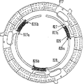
図28および29に示されている摩擦クラッチ101は、図17および18に示されている摩擦クラッチ1とは、調整リング117がコイルバネ126によって周方向に負荷されている点で本質的に異なる。摩擦ライニングの摩耗補償の機能と作動方式に関しては、調整リング117は図18〜20に従う調整リング17に対応している。図示の実施例では、クラッチケーシング2と調整リング117との間に緊張された3つのコイルばね126が円周上に均等に分布して設けられている。
特に図30から明らかなように、調整リング117は内周に半径方向の突出部もしくは段差部127を有する。これらの突出部もしくは段差部では、調整リング117を周方向に押し付けるために弓形に配置されたコイルばね126の一方の端部を支えることができる。ばね126の他方の端部範囲は、クラッチケーシング2によって支持されたストッパー128に支えられている。図示の実施例では、これらのストッパー128は、カバー2と連結しているねじ状の結合部材によって形成されている。しかしながら、これらのストッパー128は、クラッチケーシング2と一体的に形成された軸方向成形部によっても形成できる。たとえば、ストッパー128は薄板ケーシング2から軸方向に押し出したエンボス部もしくは帯金によって形成できる。特に図29および30から分かるように、少なくともほぼばね126の延長の範囲で、なるべくは摩耗調整に必要なリング117の回動角もしくはばね126の弛緩行程にわたっても、ばね126の軸方向保持および半径方向支持を保証する案内部材129が存在するように、リング117を内周に形成できる。ばね案内部材129は、図示の実施例では、断面で見て、ほぼ半円形に形成された凹部によって構成されている。これらの凹部の境界面はコイルばね126の断面にほぼ適合している。
このような構成の長所は、摩擦クラッチが回動すると、ばね126の申し分ない案内が提供されるので、これらのばねが軸方向に偏向し得ないことである。図29に示されているように、コイルばね126を追加で確保するために、カバー2はその半径方向側の縁範囲に、ばね126を軸方向に覆っている軸方向成形部130を有する。カバー2は、若干の成形部130の代わりに、円周上に連続している内縁130を付けることもできる。内縁130は皿ばね4の弛緩を制限するのに用いることができる。
図28〜30に従う調整ばね126の案内の長所は、クラッチユニット1が回転する際に、ばね126の個別コイルを遠心力の作用によって調整リング117に半径方向に支持できることである。この場合、ばね126によって周方向によって加えられる調節力は、ばねコイルと調整リング117との間で生み出される摩擦抵抗に基づいて減少するか、さらには完全に解消する。つまり、ばね126は摩擦クラッチ101が回転すると(ばね抵抗を抑圧する摩擦力に基づき)事実上剛な挙動を示す。そうすることにって、内燃機関の少なくとも無負荷回転数を越える回転数において、調整リング117はばね126によって回動され得ないようにできる。それにより、摩擦ライニングの摩耗の補償が、無負荷回転数で、もしくは少なくともほぼ無負荷回転数で摩擦クラッチ101を操作した場合のみ行われるようにすることができる。しかしながら、ライニング摩耗に基づく調整が停止した内燃機関でのみ、つまり回転していない摩擦クラッチ101でのみ行われるように、調整リング117がロックされるようにすることもできる。
摩擦クラッチ1の回転中に、もしくは所定の回転数を越えた場合に調整動作をロックすることは、図17および18に従う実施例においても好都合であり得る。このために、たとえばケーシング2に、遠心力の作用のもとで調整部材17の回動防止を、しかも脚ばね26および/または26aによって生み出された調節力に抗して引き起こす手段を設けることができる。その際、これらのロッキング手段は、少なくとも遠心力の作用で半径方向外側に圧迫可能な重量体として構成できる。この重量体は、たとえばリング17の内縁に支持され、リング17に、調節ばねによってリング17に及ぼされる回動トルクよりも大きい保持トルクを引き起こす摩擦を生み出すことができる。
ばね126の全長の少なくとも一部を半径方向に支持するために、ケーシング2によって支持される支持手段を設けることもできる。これらの支持手段は、図28および29に従う実施態様では、ストッパー128と一体的に形成できる。このために、ストッパー128は角形に形成でき、少なくともばね126の全長の一部にわたってこのばねに貫入している周方向に延びた範囲をそれぞれ1つ有する。そうすることによって、少なくともばねコイルの一部が案内され、少なくとも半径方向に支持されることができる。
図29から分かるように、図18に設けられたワイヤーリング11は省かれ、センサーばね113の舌片先端範囲に取り付けた成形部111によって置き換えられている。このために、舌片113cはそれらの先端部の範囲で、操作皿ばね4に向いた側が球状に形成されている。
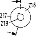
図31〜33において、リング状の調整リングの代わりに若干の調整部材217が使用されている、本発明の摩耗調整の別の変形例が示されている。これらの調節部材はカバー202の円周上に均等に分布している。調整部材217は、周方向に延び、かつ軸方向に上昇している乗り上げ傾斜面218を有する、ボタン状もしくはプレート状の部材によって形成されている。リング状の調整部材217は中心的な貫通部もしくは穴219を有する。これらの貫通部もしくは穴を通して、カバーによって支持されている軸方向のピン状の突起215aが延びており、リング状の調整部材217はこれらの突起215aに回転可能に支持されている。カバー202には、傾斜面218に対する対向乗り上げ傾斜面224をなすエンボス加工部225が設けられている。調整部材217とカバー202との間には、調整を引き起こす回転方向に調整部材217を押し付けるばね部材226が緊定されている。図31から分かるように、ばね部材226は軸方向突起215aを中心に延びており、したがってコイルばねと類似に形成されている。ばね226の端部範囲では、一方のばね端部をケーシング202で支え、他方のばね端部を対応する調整部材217で支えるために、成形部、たとえば屈曲部や脚部が設けられている。旋回サポート205範囲で皿ばね204もしくはセンサーばね213が軸方向に移動すると、調整部材217が回動し、傾斜面218が傾斜面224に乗り上げることによってこの移動が補償される。
センサー皿ばね213をケーシング202で軸方向に支持することは、ケーシング202の軸方向に延びている範囲から作り出し、半径方向内側に向かってセンサーばね213の外側範囲の下に押し込まれた帯金214を用いて行われる。
リング状の調整部材217の長所は、それらの調整角に関して十分遠心力に依存するように構成できる点である。
図31に示された回転もしくは回動する調整部材217の代わりに、摩耗調整のために半径方向および/または周方向に移動可能な、若干の楔形の調整部材を用いることもできる。これらの楔形の調整部材は、対応する調整部材を案内するために軸方向突起215aが入ることのできる細長い貫通部を持つことができる。楔形の調整部材は、これらの作用する遠心力に基づいて調整的に作用できる。しかしながら、楔形の調整部材を調整方向に押し付ける力貯蔵手段を設けることもできる。楔形の調整部材を申し分なく案内するために、ケーシング202は成形部を有することができる。摩擦クラッチの回転軸に対して直角に延びている面に対して所定の乗り上げ角度で延びている調整部材の楔面が、ケーシング側および/または操作皿ばねの側に設けられている。このような楔形の個別部材を用いる場合は、これらに作用する遠心力を最小限に押さえるために、これらの個別部材を軽量材料から作ることが好ましい。
調整ランプを構成している部材の間の材料の組み合わせは、摩擦クラッチの使用期間にわたり、乗り上げ傾斜面と対向傾斜面との間に調整を妨害する付着が発生しないように選択することが好ましい。このような付着を避けるために、少なくともこれらの部材の1つに、傾斜面もしくは対向傾斜面の範囲で被覆を設けることができる。このような被覆により、特に2つの金属部材を使用した場合に腐食を避けることができる。さらに、調整ランプを構成する部材の間の付着もしくは固着は、上下に支持し合う傾斜面および対向傾斜面を構成している部材が異なる膨張係数を有する材料で作られており、調整ランプをなしている接触している面が、摩擦クラッチの動作中に発生する温度変化に基づいて互いに相対的に動くことによって避けることができる。そうすることによって、乗り上げ傾斜面および対向傾斜面を構成している部材は、常に互いに相対的に動くように保持される。これらの部材の間に付着もしくは固着は生じ得ない。なぜならば、これらの部材は異なる膨張のために絶えず互いに再び離れたり外れたりしているからである。調整ランプを外すことは、部材の異なる強度および/または構成に基づき、これらの部材に作用する遠心力が異なる伸びもしくは運動を引き起こし、それによってまた部材の付着もしくは固着を避けることによっても実現できる。
乗り上げ傾斜面と対向傾斜面との間の付着を避けるために、摩擦クラッチの解離もしくは摩耗調整において、軸方向力を調整部材に及ぼす、少なくとも1つの装置が設けられている。このために、調整部材17、117は、摩耗が発生すると軸方向に移動する範囲を有する部材と軸方向に連結できる。この連結は、特に旋回軸受5の範囲で、しかも操作皿ばね4および/またはセンサーばね13によって行われることができる。
図34に従うグラフには、圧着皿ばねによって加えられる力が比較的小さい(約450Nm)底点もしくは最小値345を有する圧着皿ばね特性曲線340が示されている。行程・力特性曲線340を有する皿ばねの最大値は、7600Nm程度である。特性曲線340は、半径方向に隔たった2つの支持部材の間で皿ばねが変形することによって、しかも図24に従う特性曲線40に関連して、また皿ばね4との関連で説明したように生み出される。
皿ばね特性曲線340は、ライニングばね特性曲線342と組み合わせることができる。図34から分かるように、ライニングばね特性曲線342の行程・力曲線は、圧着皿ばね特性曲線340に接近し、もしくは2つの特性曲線は互いにわずかな間隔で延びているので、対応する摩擦クラッチは非常にわずかな力で操作することができる。ライニングばねの作用範囲では、垂直方向に上下している線340と342の2つの点の差から解離力が生じる。このような差が360で示されている。実際に必要な解離力は、皿ばね舌片などの操作部材の対応するてこ比だけ減少する。これは、やはり図17および18に従う実施態様および図24〜27に従うグラフと関連して説明した。
図34には、最大値もしくは底点445を有するもう1つの操作皿ばね特性曲線440が破線で示されている。この底点では、皿ばねによって加えられる力が負であり、したがって対応する摩擦クラッチの接続方向ではなく、解離方向に作用する。これは、解離段階で点461を越えると、摩擦クラッチが自動的に開いたままであることを意味する。皿ばね特性曲線440には線442に従うライニングばね特性曲線を付属させることができるが、最小解離力を得るために、ライニングばね曲線442と皿ばね特性曲線440とのできるだけ平行な推移が求められる。
図35には、対応する摩擦クラッチを解離するために皿ばね舌片などの操作レバーに加えられる解離力の推移が、付属する特性曲線340および342もしくは440および442に対する解離行程にわたって示されている。ここで分かるように、特性曲線340、342に付属している解離力の推移349は、常に正の力範囲にある。つまり、クラッチを解離した状態で保持するために、解離方向に常に力が必要なのである。特性曲線440および442に付属している解離力の推移は、部分範囲449aを有する。この部分範囲では、解離力が最初に減少し、次に正の力範囲から負の力範囲に移行するので、対応する摩擦クラッチは解離した状態で保持力を必要としない。
図36、36aおよび37に示された摩擦クラッチ501の実施態様では、センサーばね513はクラッチカバー502で軸方向にバヨネット式結合部514を介して支持されている。このために、センサーばね513は半径方向にリング状の基体513bの外周から延びている帯金513dを有する。これらの帯金は、カバー材料から作り出した帯金として、半径方向範囲502aに軸方向に支えられている。カバー帯金502aは、ほぼ軸方向に延びいてるカバーの縁範囲502bから作り出されているが、そのために帯金502aが少なくとも一部がカバー材料から最初に切り抜き502cまたは502dによって作り出されていることが好都合である。帯金502aの輪郭の少なくとも一部を裁断することによって、これらの帯金はより簡単にそれらの目標位置に変形できる。特に図37から分かるように、これらの帯金502aおよびブラケットもしくは舌片513dは、センサーばね513のカバーに対する心出しを行うころができるように互いに同調している。図示の実施例では、帯金502aはこのために小さく軸方向段差部502eを有する。
バヨネット式ロック部材514を作る間、センサーばね513をケーシング502に対して申し分なく位置決めできるようにするために、なるべくはカバー502の円周上に均等に分布した、少なくとも3つの帯金502aが、別のカバー範囲を基準にして同調されているので、センサーばね513とカバー502との間の所定の相対的回動の後に、対応するブラケット513dが円周ストッパー502fに当たり、そうすることによってセンサーばね513とカバー502との間のそれ以上の相対的回動が避けられる。特に図36aに明らかなように、図示の実施例においてストッパー502fはカバー502の軸方向段差部によって形成されている。さらに図36aから明らかなように、少なくとも若干の、なるべくは3つの帯金502aは、カバー502とセンサーばね513の舌片513dとの間で、もう1つの回動制限部材502gを構成する。図示の例では、等しい帯金502aが2つの回転方向に対して回動防止部材502fおよび502gを構成している。センサーばね513とカバー502との間のロック解除を防ぐストッパー502gは、舌片502aの、半径方向に延びた軸方向の曲げ縁によって形成されている。円周ストッパー502fおよび502gにより、センサーばね513はカバー502に対して周方向の所定の位置に決められている。ロック部材514を作るために、センサーばね513は軸方向にカバー502に向かって緊定されているので、舌片513dは軸方向に切り抜き502cおよび502dの中に入り、軸方向カバー支持部材502aの上に来る。その後で、カバー502とセンサーばね513とは、舌片513dの幾つかが回動制限部材502fと当たるまで互いに相対的に回動できる。それからセンサーばね513の部分的な弛緩が行われるので、舌片513dの幾つかは、周方向に見て対応するストッパー502fと502gの間に来て、そしてすべての舌片513dがカバーが支持部502aに載る。本発明に従うバヨネット式ロック部材514の構成により、摩擦クラッチ501を取り付ける際に、舌片513dはカバー側サポート502aの横には来ないことが保証される。
これまで示した実施例では、センサーばね513の本来のばね力を加える円環状の基体、たとえば513bが、作用範囲もしくは支持範囲の半径方向外部でプレッシャープレートと操作皿ばねとの間に設けられている。しかしながら、若干の応用例にとって、センサーばねの円環状の基体が、作用直径の半径方向内部でプレッシャープレートと操作皿ばねとの間に設けられていることも好都合であり得る。これはつまり、図17および18に従う実施態様について、センサーばね13の軸方向の緊定力を加える基体13bが、作用範囲3aの半径方向内部で操作皿ばね4とプレッシャープレート3との間に設けられていることを意味する。
図36〜37に従う実施例で、カバー側の対向乗り上げ傾斜面524が、薄板ケーシング502に取り付けたカム状のエンボス部によって形成されている。さらに、この実施態様においては、ケーシング502と調整リング517との間に規定されたコイルばね526が、調整リング517と一体的に形成されて周方向に延びているガイドピン528によって案内されている。特に図21から明らかなように、ガイドピン528は軸方向に、ばね526の内径に適合した細長い断面を有する。ガイドピン528は、少なくともばね526の全長の一部にわたってばねに貫入している。それによって少なくともばねコイルの一部を案内し、少なくとも半径方向に支持することができる。さらに、軸方向におけるばね526の座屈もしくは飛び出しを避けることができる。ガイドピン528によって、摩擦クラッチの取り付けは大幅に容易にできる。
図38に、調整リング517が一部示されている。調整リング517は半径方向内側に向かって延びている成形部527を有する。この成形部は、コイルばね526のための、周方向に延びているピン状の案内範囲528を支持している。図示の実施例では、ばね受け範囲528は、射出成形部として作られたプラスチックリング517と一体的に形成されている。しかしながら、ばね案内範囲もしくはばね受け範囲528は、若干の部材またはすべて共通に唯一の部材から形成でき、これらが調整リング517と、たとえばクリップロック機構を介して結合される。だから、すべての案内範囲528は場合によって円周が開いたリングによって形成できる。このリングは、なるべくはスナップ結合部として構成された、少なくとも3つの結合箇所を介して調整リング517と組み合わされている。
図28および29との関連で説明したのと同じように、コイルばね526を、たとえば遠心力作用などに基づいて、カバー502および/または調整リング517の、対応して形成された範囲で半径方向に追加で支えることができる。
コイルばね526に対するカバー側支持部は、カバー材料から作り出されて軸方向に延びている翼部または軸方向の壁を形成しているエンボス加工部526aによって形成されている。その際、ばねの対応する端部が案内され、それによって軸方向および/または半径方向に許容されない移動をすることがないように、ばね526の支持範囲としてのエンボス加工部526aが形成されていることが好都合である。
図39に示されたクラッチ601の実施態様において、センサーばね613はケーシング602の、プレッシャープレート603とは反対側に設けられている。プレッシャープレート603を収容しているるケーシング空間の外部にセンサーばね613を配置することによって、センサーばね613に対する熱負荷を低減できる。そうすることによって、このばね613が熱負荷によって減衰する危険は避けられる。ケーシング602の外側でも、ばね613のより良好な冷却が行われる。
操作皿ばね604の、カバーとは反対側に設けられた旋回サポート611の支持は、スペーサーリベット615を介して行われる。これらのスペーサーリベットは、皿ばね604およびケーシング602の対応する貫通部を通って軸方向に延びており、センサーばね613と軸方向に結合している。図示の実施例では、スペーサーリベット615はセンサーばね613とリベット止めされている。スペーサーリベット615の代わりに、転動サポート611とセンサーばね613との間の結合を作る他の手段を用いることもできる。そこで、たとえば、センサーばね613は半径方向内側の範囲にね軸方向に延びている帯金を有することができるよう。これらの帯金は転動サポート611を対応する半径方向範囲で支持し、またはそれどころかこの転動サポート611を対応する成形部で直接形成する。センサーばねに固くリベット止めされた部材615の代わりに、別様に形成された、たとえばセンサーにヒンジ状に凍結された部材を用いることもできる。
図40に従う実施例において、センサーばね713は操作皿ばね704に対する旋回サポート715の半径方向内部で延びている。センサーばね713は、その半径方向内側の範囲でカバー702に支持されている。そのために、カバー702は、皿ばね704の対応するスロットもしくは貫通部を通って軸方向に延びた帯金715を有する。これらの帯金はセンサー皿ばね713を軸方向で支えている。
図41に示された調整リング817は、図20〜21に従う摩擦クラッチに使用できる。調整リング817は、半径方向に延びている半径方向内側の成形部827を有する。成形部827は、周方向でクラッチカバーと調節リング817との間に緊定されているコイルばね826のための支持範囲をなす半径方向突起827aを有する。コイルばね826の取り付けを案内し容易にするために、外周を中断もしくは開けているリング528が設けられている。リング828は半径方向成形部827aと結合している。このために成形部827aは、周方向に延びた凹部もしくは溝を有する。これらの凹部もしくは溝は、リング828と組み合わせてスナップ結合部を構成するように形成されている。調整皿ばね826のカバー側支持部は、クラッチカバーの軸方向帯金826aによって形成されている。軸方向帯金826aは、リング828を収容するための軸方向切り欠き部826bを1つずつ有する。この場合、切り欠き部826bは、リング828が帯金826aに対して、少なくとも摩擦クラッチの摩耗量に応じて軸方向に移動できるように形成されている。このために、半径方向成形部827aに取り付けた、リング828を保持するための凹部と切片826bとが、軸方向に見て逆方向に形成されていること、言い換えれば、成形部827aにおける凹部が一方の軸方向に、切片826bが他方の軸方向に開いていることが、好ましい。
図42に示された摩擦クラッチ901の実施態様におはて、操作皿ばね904の解離方向における支持が、皿ばね904の基体904aの中央範囲で行われる。この基体904aは半径方向外側でプレッシャープレート903に支えられ、半径方向内側に向かって旋回軸受905を越えている。つまり、旋回軸受905は、皿ばね904の基体904aの内縁、もしくは皿ばね904の舌片を形成しているスロット端部から、従来知られている皿ばねクラッチと比べて比較的大きく離れている。図示の実施例では、旋回軸受905の半径方向内部に設けられている基体範囲と、旋回軸受905の半径方向外部にある基体範囲との半径方向幅比は、1:2程度である。この比が1:6と1:2の間にあれば好ましい。操作皿ばね904をこのように支持することにより、旋回軸受905の範囲で皿ばね基泰904aの破損もしくは過負荷を避けることができる。
さらに、図42には、プレッシャープレート903に設けられた軸方向成形部903aが破線で暗示されている。プレッシャープレート903、特に支持カム903bの範囲に設けられたこのような成形部903aを介して、操作皿ばね904をクラッチ901に対して心出しできる。つまり、操作皿ばね904は外径心出しを通してカバー902に対して半径方向に保持できるので、やはり図42に示されている心出しリベットもしくはボルト915は省略できる。図示されていかいが、外径心出しはカバー902の材料から作り出された帯金または成形部を介しても行うことができる。
摩擦クラッチ901において、力を加える基体913aがカム903bの半径方向内部に設けられているセンサーばね913が形成されている。一方では操作皿ばね904を支持するために、他方ではカバー902を独自に支持するために、センサーばね913は半径方向ブラケットもしくは舌片を有する。これらのブラケットもしくは舌片は一方では基体913aから半径方向内側に向かって延び、他方では基体913aから出て半径方向外側に向かって延びている。
図43に示された摩擦クラッチ1001の変形例では、摩擦クラッチの解離力もしくは操作皿ばね1004の旋回力とは反対方向の力が、ケーシング1002とプレッシャープレート1003との間で軸方向に緊定されたセンサーばね1013によって加えられている。このような実施態様において、操作皿ばね1004は旋回範囲もしくは傾倒範囲1005で旋回軸受によって解離方向に支持されていない。カバー側旋回軸受もしくは支持サポート1012における皿ばね1004の衝止は、センサーばね1013の張力によって保証されている。このセンサーばねは、摩擦クラッチ1001の解離動作中に、このセンサーばね1013によって皿ばね1004に加えられる軸方向力が、摩擦クラッチ1001の必要な解離力よりも大きいか、大きくなるように設計されている。その際、皿ばね1004が絶えずカバー側支持部もしくは旋回サポート1012に当たっていることが保証されていなければならない。このために、以上の実施態様に関連して説明したのと類似の仕方で、軸方向に働いて互いに重なる力が同調されなければならない。センサーばね1013、プレッシャープレート1003とケーシング1002との間に場合により設けられている板ばね部材によるライニングばね、操作皿ばね1004、摩擦クラッチ1001の解離力および調整リング1017に作用する調整部材によって生み出されるこれらの力は、互いに同調されなければならない。
図44に従う摩擦クラッチ1101において、センサーばね1113はカバー側のリング状の支持範囲1112の半径方向外部に支持されている。図示の実施例では、操作皿ばね1104とセンサーばね1113との間の相互支持が、プレッシャープレート1103において操作皿ばね1104の支持直径1103aの半径方向外部でも設けられている。センサーばね1113はカバー1102で支持されるために、半径方向外側に、半径方向外側に向いたアーム1113bとして形成された成形部を有する。これらのアームは図36〜37との関連で説明したのと類似の仕方で、バヨネット式ロック1514を介してカバー1102に軸方向に支持され、回動しないようにされている。センサーばね1113を取り付けるために、カバー1102は、対応する軸方向貫通部1502bを有する。これらの貫通部には、バヨネット式ロック1514を作るためにセンサーばね1113の半径方向外側の支持アームを差し込むことができる。皿ばね1104がカバー側旋回サポートもしくは支持サポート1112に当たることが、センサーばね1113の張力によって保証されている。
図43との関連で、クラッチの機能を詳細に説明する。ここでは、センサーばねのばね力は、調整点における解離力に対応するように設計されている。ライニング摩耗(または他の箇所における摩耗)が生じ、したがって皿ばね角度が変化し、それによって皿ばね力が増して解離すると、皿ばねは最初にサポート1012を中心に調整点近傍まで旋回する。次に、この点では解離力はセンサー力およびライニングばね弾性(残留力)と等しくなり、皿ばねはさらに解離するとプレッシャープレートのサポートを中心にして、解離力とセンサー力との間で再び力の平衡が生み出されるまで旋回する。その際、皿ばねはカバー側サポートから持ち上がり、このサポートを調整用に解除する。それ以後の解離行程にわたって解離力はさらに減少してセンサー力が勝り、プレッシャープレートを通して皿ばねをカバー側サポート1012に押し付ける。このとき、皿ばねはこのサポートを中心にして、さらに旋回する。皿ばねがカバー側支持からプレッシャープレート側支持に移行するときに、皿ばね2アーム式レバーとしての機能を傾向的に変化させる。皿ばねはプレッシャープレートで一時的にこのとき存在している解離力でプレッシャープレートに支えられ、それによって一時的にカバー側サポートから持ち上がる。さらに解離すると、これに伴う力の減少に基づき、センサーばねの力が勝り、皿ばねを再びカバー側サポートに押す。そうすることによって、調整装置はロックされ、調整動作が終了する。皿ばねはそれ以後の解離行程については、再び2アーム式レバーとして働く。皿ばねは、皿ばねに対して間接または直接に作用するすべてのばね力を考慮して設計される。これには特に、操作皿ばね、および対応する補償装置もしくは調整装置の、カバーに対して軸方向に移動可能な部材によって生み出される力が属している。
さらに、図44に従う実施例の長所は、摩擦クラッチが接続した状態で皿ばね1104が事実上2アーム式レバーとして緊定され、もしくは働き、したがって皿ばね1104がカバー側支持部1112とプレッシャープレート側支持部1103aとの間で緊定されているが、摩擦クラッチ1101が解離すると皿ばねは事実上センサーばね1113だけ支えられ、支持範囲1113aを中心にした旋回し、同時に支持範囲1113aが軸方向に移動するので、皿ばねは事実上1アーム式レバーとして働く点である。
図44に従うセンサーばね1113は、他の図のセンサー皿ばねと同様に、対応して設計もしくは適合されると、操作皿ばね1104の任意の直径に支えられることができる。たとえば、皿ばね1104におけるセンサーばね1113の支持は、カバー側旋回範囲1105と、プレッシャープレート側支持直径1103aとの間にある直径でも行うことができる。さらに、皿ばね1104におけるセンサーばね1113の支持は、カバー側支持直径1105の半径方向内部でも設けることができよう。その際、皿ばね1104における支持直径1113aが小さいほど、センサーばね1113によって加えられる軸方向支持力は傾向的に大きくなる。さらに、ばね1104と1113との間の支持直径1113aが、皿ばね1104のカバー側支持直径から離れているほど、センサーばね1113の事実上一定を有するばね範囲は大きくならなければならない。
図45に従う実施例は、先行の図、特に図17〜30との関連で説明したのと類似の仕方で働く調整装置1216を有する。操作皿ばね1204は、2つのリング状の転動サポート1211と1212との間で旋回可能に支持されている。プレッシャープレート1203と隣接しているサポート1211−、センサーばね1213の作用を受けている。摩擦クラッチ1201は、摩擦クラッチの寿命にわたって、調整リング1217の傾斜面がカバー側に設けられた対向傾斜面に付着しないことを保証する装置1261を有する。図示の実施例では、図18との関連で説明したように、対向傾斜面がカバーに回転不能に固定された支持リング1225に設けられている。傾斜面と対向傾斜面が付着すると、所望の摩耗調整はもはや起こらないであろう。
装置1261は、引き離し機構を構成している。この引き離し機構は、摩擦クラッチ1201が解離し、摩擦ライニング1207に摩耗があると調整リング1217に軸方向力を及ぼすことがてぎ、そうすることによって場合によって存在する傾斜面と対向傾斜面との間の付着が外される。この機構1261は、図示の実施例で皿ばね1204と軸方向に結合した、軸方向にばね弾性的な部材1262を包含している。この部材1262は、半径方向外側で皿ばね1204と結合した、膜状もしくは皿ばね状にばね弾性的なリング状の基体1262aを有する。リング状の基体1262aの半径方向内側の縁範囲から、円周上に分布している軸方向帯金1263が延びている。これらの帯金は皿ばね1204の軸方向貫通部を貫通している。帯金1263はそれらの自由端範囲に、調整リング1217の対向衝止輪郭1265と協働すると、屈曲部1264の形をした衝止輪郭を有する。対向衝止輪郭1265は、リング1217に半径方向に設けられたへこみ部または全周の溝によって形成されている。摩擦クラッチが接続した状態における衝止輪郭1264と対向衝止輪郭1265との間隔は、少なくともクラッチ解離段階の大部分にわたって、輪郭1264と対向輪郭1265との接触が起こらないように選択されている。摩擦クラッチが完全に解離して初めて衝止輪郭1264は対向輪郭1265に当たることが好ましい。そうすることによって、部材1262は調整リング1217と皿ばね1204との間で弾性的に緊定できる。それによって、ライニング摩耗の結果、旋回サポート1211の軸方向移動が行われるとすぐに、調整リング1217が強制的にカバー側乗り上げ傾斜面から持ち上げられることが保証される。さらに、機構1261は、たとえばレリーズシステムの誤った基本調整に基づいて解離行程が大きすぎる場合に、リング1217の調整が行われるのを防ぐ。これは、皿ばねの解離方向への旋回行程が大きすぎる場合に、ばね弾性部材1262が調整リング1217を皿ばね1204に向かって押し付けることによって実現される。そうすることによって、調整リング1217が皿ばね1204に対して回動しないようにされる。つまり、図24に従い点46を越えると、調整リング1217が皿ばね1204に対して回転不能に保持されることが保証されていなければならない。なぜならば、点46を越えるとセンサーばね1213の保持力が克服され、それによってクラッチディスクに摩耗がない場合でも調整が行われるであろうからである。その結果、動作点の変化、つまり皿ばね1204の取り付け位置の変化が、しかもより小さい圧着力の方向で生じるであろう。これは、図24で動作点41は特性曲線40に沿って45で表示した最小値に向かって移動するであろう、ということを意味する。
図46〜48に従う細部に対応して構成された摩擦クラッチの実施態様において、若干のコイルばね1326が、クラッチカバー1302と一体的に形成された帯金1328に保持されている。これらの帯金1328はカバー1302の薄板材料から、たとえば打ち抜いたU字形の切り抜き部1302aを形成することによって作られている。帯金1328は、周方向に見て、弓状または接線状に延びており、直接隣接するカバー範囲と少なくともほぼ同じ高さにあることが好ましい。図48から分かるように、図示の実施例では、帯金1328はほぼ材料の半分の厚さだけカバーの底範囲1302bに向かってずれている。帯金1328の幅は、その上に設けられているコイルばね1326が半径方向にも、軸方向にも案内されているように選択されている。
ばね1326によって調整方向に作用を受けている調整リング1317は、カバー1302と皿ばね1304との間の延び、内周に半径方向内側に向いた成形部もしくはブラケット1327を有する。ブラケット1327は半径方向内側に、軸方向に向いたフォークもしくはU字形成形部1327aを有し、軸方向に向いたそれらの歯1327bは、案内帯金1328を両側で包囲している。このために、2つの歯1327bはカバー1302の切片1302aを通って軸方向に延びている。成形部1327aもしくはそれらの歯1327bには、調整ばね1326が支持されている。
調整リング1317は、先行の図に関連して説明したのと類似の仕方で、乗り上げ傾斜面を介してカバー1302にエンボス加工された対向乗り上げ傾斜面1324に支持されている。しかしながら、対向乗り上げ傾斜面1324をなしているカバーのエンボス加工部は、クラッチの回転方向に空気孔1324を作る.ように形成されている。このように構成することによって、対応する摩擦クラッチが回転すると、強制的な空気循環により摩擦クラッチのより良好な冷却が実現される。特にそうすることによって、プラスチックから作られた調整リング1317も冷却され、それによってこの部材の熱負荷も大幅に減少できる。
その他の変形例に従い、摩擦クラッチの操作皿ばねに作用するセンサー力は、たとえばクラッチケーシングとプレッシャープレートとの間に設けられている板ばね部材によって加えられる。その際、これらの板ばね部材は、プレッシャープレートとケーシングを回転不能に、しかしながら軸方向に限定的に相対的に相互に移動可能に連結できる。このような実施態様においては特別のセンサーばねは必要なく、たとえば図1および2に従う摩擦クラッチ1の板ばね9は、さらにセンサー皿ばね13の機能も引き受けるようにように形成できるであろう。それによって、センサーばね13も転動リング11も省くことができる。この場合、板ばね部材9は、摩擦クラッチ1を操作する間、ライニング摩耗がなければ、操作皿ばね4がカバー側転動サポート12に接しているように形成できなければならない。しかしながら、摩擦ライニング7に対応する摩耗が生じ、それによって皿ばね4の解離力が増加するとすぐに、板ばね部材9は摩耗に対応する皿ばね4の対応した調整を可能にする。摩擦クラッチに埋め込まれた板ばね部材は、摩擦クラッチもしくはプレッシャープレートの少なくとも必要な最大調整行程にわたって、事実上直線的な力・行程特性曲線を有する。これは、板ばね部材9が、図25に関連して説明したのと同様に、特性曲線47または47aにした特性曲線範囲48を有することを意味する。
本発明は図示および説明した実施例の制限されるものではなく、特に本発明に関連して説明した特徴もしくは部材の組み合わせによって構成できる変形例も含む。さらに、図との関連で説明した個々の特徴もしくは機能方式は、それ自体で見れば独立した発明と見なされる。
したがって、出願人は、これまで単に発明の詳細な説明の中で、特に図との関連で開示された、発明にとって重要な意味を持つその他の特徴を請求する権利を留保する。したがって、この出願によって提出される特許請求の範囲は、方式化の提案にすぎす、より広範な特許保護を得るための不利益を伴うものではない。The present invention relates to a clutch unit with a friction clutch having a pressure plate, wherein the pressure plate can be connected to an opposing pressure plate non-rotatably but to some extent in the axial direction, in which case at least one compression spring The pressure spring loads the pressure plate towards the clutch disc which can be tightened between the pressure plate and the opposing pressure plate, and at least compensates for the wear of the friction lining of the clutch disc. Means are provided, the adjusting means applies a constant force to the pressure plate by the pressure spring, and the friction clutch further comprises operating means for disengagement and connection. , This operating means is dissociating means, eg On what format operable by axially movable shifter by pivotally hinged dissociation fork into play transmission casing.
A clutch unit constructed and operated in this way is proposed by FR-OS 2582363. Operating means of this type of clutch unit are described, for example, in US-PS 4,368,810, US-PS 4,326,617, DE-OS 2752904 and DE-OS 2801999. Loaded by dissociation means and shifters as proposed.
In a clutch unit or a friction clutch with integral adjustment means for compensating wear of at least the friction lining of the clutch disc, the movement of the clutch pedal is effected by interposition of at least one disengagement bearing via a rod and / or Bowden cable. In connection with the so-called mechanical disengagement mechanism, which is transmitted to the operating means of the friction clutch, the shifter area which loads the operating means is compared with the loaded area of the operating means based on the errors present in the entire chain of movement. Therefore, the frictional clutch does not always have the same axial position, so that there is a problem that a relatively large variation occurs in the disengagement stroke of the friction clutch or the operation stroke transmitted to the operation means. Due to this variation, the function of the adjusting means may be impaired, and in some cases may be lost altogether. Furthermore, if the operating means goes through an unacceptably large stroke, an undesired post-adjustment is effected, whereby the friction clutch is not fully released or the preloading or mounting position of the pressure spring is reduced. And the force produced by this crimp spring becomes insufficient, resulting in insufficient torque transmission being compensated.
The object of the invention is to provide a clutch unit of the type mentioned at the outset in which the above disadvantages are avoided and a sufficient function of the adjusting means for compensating the wear of the friction lining is obtained, and this clutch unit is particularly simple. And to make it cheaper to manufacture.
The gist of the present invention that solves this problem is to provide a means for compensating for the axial variation of the position of the operating means or the axial variation of the position of the operating means area loaded by the shifter with respect to the shifter or the dissociating means. Is to be. This type of measure is particularly advantageous with regard to the wear of the friction lining in the clutch unit according to the invention in which the operating means are arranged in the axial direction of the disengagement movement. This ensures a playless force transfer between the shifter or disengaging means and the operating means. This further ensures that the operating means always moves by the same amount. Therefore, there is virtually no play in the force transmission path between the shifter and / or the disengaging means and the operating means.
It is particularly advantageous if compensation means are provided or act between the shifter and the operating means in the axial direction. However, it is also possible to provide the compensating means at other positions, for example functionally between the shifter and the dissociating means. In the context of the present invention, it is advantageous if the shifter is advantageously mounted on a guide provided on the transmission side, for example a guide tube surrounding the input shaft of the transmission.
In particular, in a casing with a bottom facing the shifter and fixed to an opposing pressure plate, for example in a clutch unit with a friction clutch having a thin plate cover, the compensating means is arranged axially between the operating means and the bottom or It is effective when it works. Furthermore, the pressure spring is formed by a disc spring preloaded axially between the clutch casing and the pressure plate, the disc spring extending radially inward from the spring-elastic annular base and from the base. It is advantageous to have a tongue which forms the operating means.
In order to ensure sufficient post-adjustment by the compensating means, the compensating means automatically or spontaneously compensates for sufficient post-adjustment when the clutch unit or the friction clutch is connected, and voluntarily or automatically during operation of the friction clutch. Advantageously, it is locked in place.
The compensating means may comprise an annular member which, even in the engaged state of the friction clutch, abuts the operating means in the axial direction. Even if the distance between the load area of the operating means and the shifter changes due to the annular member, the change is compensated. For the function of the compensating means, it is advantageous if the compensating means has an axially rising rear adjusting ramp or a climbing ramp, in which case the ramp can be provided on the annular element.
The climbing ramp can cooperate with a cylindrical or spherical rolling element for rear adjustment. However, the climbing ramp advantageously cooperates with the opposite climbing ramp. The reason for this is that by appropriately selecting the climbing angle of the latter inclined plane, a self-locking action occurs when the inclined plane is tensioned in the axial direction. The opposite climbing ramp may likewise be supported by an annular member.
In order to ensure a cost-effective manufacture of the friction clutch, it is advantageous if at least part of the compensation means is made of plastic. Such plastic parts can be produced by injection molding. Suitable plastics are particularly preferably thermoplastics, for example polyamides.
It is particularly advantageous if the component with the rear adjustment ramp can be moved axially during operation of the clutch unit or the friction clutch. Furthermore, it is advantageous if the members provided with the inclining ramp and the opposing inclining ramp are rotatable relative to one another, in which case one of these members cannot rotate relative to the friction clutch, in particular the clutch casing. There can be.
According to another aspect of the invention, in the disengagement direction of the clutch unit, the compensating means acts in a manner similar to a freewheel or is post-adjusted and has a self-locking action in a direction opposite to the disengagement direction. Means can be configured. To this end, the climbing ramp and / or the opposing climbing ramp can be formed with an elevation angle in the axial direction of 5 ° to 20 °, preferably of the order of 7 ° to 11 °. . The rear adjustment ramp is preferably formed such that self-locking takes place by frictional engagement. In short, care must be taken that in any case the rear adjustment ramps engage with self-locking and thus do not require the additional measures necessary to avoid unwanted return. . However, additional means can be provided if necessary.
In order to ensure a sufficient functioning of the spontaneous compensating means, it is advantageous if at least one element with a ramp and / or an opposing ramp is spring-loaded in the rearward adjustment direction. It is advantageous if the spring load is such that the function of other springs, for example, in particular crimp springs or disc springs, and the springs which give rise to an axially resilient contact is not or is not affected. A particularly advantageous configuration is assured if the component with the inclining ramp and the opposing inclining ramp is loaded or tensioned in the rear-adjusting direction by a power storage device arranged between them, for example a coil spring. You. Due to this tension, the two members are pressed in opposite directions as viewed in the axial direction, and are separated from each other in the axial direction via the energy storage device and the rear adjustment inclined surface. In the clutch engaged state, this causes the compensating means to be tensioned axially without play between the load area of the operating means and the clutch cover and / or the shifter.
According to a particularly advantageous configuration of the invention, the clutch unit can have at least means for limiting the disengagement movement of the operating means. For this purpose, a limiting stopper can be provided which limits the travel of the shifter and / or the dissociating means in the dissociation direction. The limiting stop is advantageously formed in such a way that the member forming the compensating means abuts the clutch cover after a predetermined disengagement stroke. However, the restriction may be effected by the shifter having an area that abuts an axially immobile member after a predetermined disengagement stroke. It is further advantageous for the shifter to have a limiting member which can likewise be formed by a stopper in the clutch connection direction. Advantageously, the compensating means is formed such that the shifter is axially supported via the compensating means in the engaged state of the clutch unit. A constant operating stroke for the clutch unit is ensured by the fact that the element forming the compensating means has a stroke limiting region which acts in the disengagement and connection directions and cooperates with the stop region. Advantageously, this element can be formed by a component of the compensation means, which is loaded by the shifter, in which case the limiting stop can be provided on the clutch housing or formed by this housing. However, the operating stroke of the clutch unit can also be limited by providing a suitable stopper on the member for guiding the shifter in the axial direction.
This stop preferably cooperates with a component connected to the non-rotating bearing ring of the shifter. However, at least the restriction of the disengagement stroke in the axial direction can also take place between the rotating bearing ring of the shifter and a member rotating with the shifter, for example a clutch housing.
According to an additional embodiment of the invention, it is particularly advantageous to reduce the force characteristics of the shifter or the maximum required dissociation force, particularly advantageously during the dissociation process, at least over a part of the operating stroke of the operating means. Advantageously, means are provided such that the torque transmitted by the friction clutch or the clutch disc is gradually reduced. This means is formed, for example, by a so-called lining spring, which is provided between the friction linings of the clutch disc which are tightened between the pressure plate and the opposing pressure plate.
A particularly advantageous configuration of the friction clutch according to the invention is that the pressure spring, which is advantageously formed by a disc spring, is provided between two supports, one of which faces a pressure plate and is spring-loaded toward the pressure disc spring. ) Is pivotably supported by the casing. In that case, due to the compression spring, when the friction clutch is disengaged, the maximum disengagement force acting on the spring-loaded support increases during lining wear and exceeds the opposing force or support force acting on the spring-loaded support. . If a disc spring element provided between the pressure plate and the clutch housing for torque transmission and / or a lining spring, for example as known from DE-OS 36 36 163, is used, this acts on the compression spring. The force must be taken into account when determining the force acting on the spring-loaded support. The reason is that these forces overlap. This means that in order to enable post-adjustment, the increased dissociation force, which is adjusted in a short time in the presence of significant lining wear, increases the turning diameter of the disc spring caused by the various forces mentioned above. Must be large compared to the combined force related to The crimping disc spring has a characteristic curve of the force acting from the crimping disc spring at the time of reducing the load caused by the lining wear and, consequently, the level of the characteristic curve of the disengagement force, starting from the mounting position in the friction clutch defined by its structure. In a position which is deformed or unloaded relative to the defined mounting position, it is advantageous to have a characteristic curve in which the maximum force acting from the crimping disc spring decreases during the dissociation process. According to such a configuration of the crimping disc spring, when the wear occurs, at least the maximum disengagement force of the friction clutch and the combined force acting on the crimping disc spring in the opposing force or rolling diameter region acting on the spring-loaded support portion. The balance between the opposing forces is always adjusted.
The clutch unit or the friction clutch is also advantageously configured as follows. That is, an axially movable spring-loaded support is mounted on the wear-out body of the friction clutch together with the pressure plate. During the post-adjustment of the adjusting means, which takes place gradually or in finer steps, taking into account the life of the friction clutch, the spring-loaded support can move slightly towards the pressure plate. By this means, the disc springs supported by the pressure plate undergo additional deformation, which, as already mentioned, reduces the force of the disc springs and finally the counterforce acting on the spring-loaded support. Alternatively, the combined opposing force described above comes to balance with the dissociation force. In short, the maximum disengagement force of the clutch or the crimping disc spring is reduced again during the movement of the spring-loaded support.
Particularly preferably, a crimping disc spring is incorporated in the friction clutch in such a way as to produce a falling force-stroke-characteristic curve over at least a part of the disengagement area, and preferably in fact over the disengagement area of the clutch. In this case, the mounting position of the compression spring is selected such that the compression spring actually reaches the minimum or the lowest point of its sine curve force, stroke and characteristic curve when the friction clutch is disengaged.
The opposing force acting on the spring-loaded support can advantageously be obtained by a power storage device which produces a substantially constant force at least over the rear adjustment area. For this purpose, disc springs which are suitably formed and which are integrated under preload into a friction clutch are particularly suitable for this.
The present invention is not limited to the above-described friction clutch, but can be generally used in a friction clutch or a clutch unit provided with at least an adjusting means for compensating wear of the friction lining of the clutch disk.
The invention further provides a friction clutch, especially for motor vehicles, comprising a pressure plate coupled to the casing so as to be pivotally immovable and slightly movable in the axial direction, wherein a crimping disc spring is provided between the casing and the pressure plate in the axial direction. A clutch disc which is inserted under a preload and which can be swiveled about a swivel bearing supported by a casing and which has a pressure plate fastened between it and an opposing pressure plate, for example a flywheel. , In which case adjustment means are provided for compensating wear of the friction lining of the clutch disc.
Automatic post-adjustment devices in which the pressure plate always produces a constant force load on the pressure plate by means of crimping disc springs are known, for example, from DE-OS 29 16 755 and DE 3518781. This adjusting device, which is adjusted in dependence on at least one sensor, is arranged or acts between the pressure plate and the crimping disc spring. The pivotal attachment of the pressure plate to the casing is effected by a tangentially arranged leaf spring, the force of which is relatively small since the leaf spring is oriented against the pressure force of the disc spring. Therefore, the pressure plate having a relatively large mass oscillates in the axial direction when the friction clutch is disengaged, and separates from the disc spring at that time, which not only impairs the function of the clutch but also reduces the safety of the clutch. At risk. This is because the post-adjustment device is post-adjusted in the open state, until the pressure plate abuts the clutch disc and the clutch can no longer be disengaged. For this reason, such post-adjustment devices are not really widespread.
Yet another object of the invention is to eliminate these drawbacks, to be widely used in the field and to be used for rough driving, not only to have a simple structure and to have a long lasting function, but also to require a small amount of mounting space, and to be manufactured. It is an object of the present invention to provide an inexpensive mode of adjustment. In addition, the required disengagement forces are small and always small over the service life, and the service life of the friction clutch must be significantly increased.
According to the present invention that solves this problem, in a friction clutch having a pressure plate loaded by a disc spring, a pressing force is generated by the disc spring, and the disc spring is supported by a component member, for example, the casing, and is attached to the casing. A post-adjustment device is provided between the cover and the disc spring, which is capable of pivoting around a pivot bearing provided in a circular arrangement, and which separates the casing-side support from the casing depending on wear. In this case, the adjusting device can be moved by the forward feed device, and the disc spring is subjected to a supporting force toward the pivot bearing. This supporting force is effectively and permanently present, so that the disc spring can only transmit force against the disengagement force, which is also supported by the spring force without the aid of matingly pivoted means. I have. The disc spring has a gradual characteristic curve over its working area, so that the supporting force is maintained by the disc spring in the installed position of the disc spring and without a change in conicity due to wear and over the disengagement stroke of the disc spring. When the conicality of the disc spring changes depending on the wear, the supporting force is increased over a part of the dissociation process of the disc spring when the conicality of the disc spring changes depending on the force acting against the supporting force. The supporting force and the disc spring are combined with each other so as to be smaller than the force of the disc spring against the force. The supporting force is then generated by only one spring element or at least approximately only one spring element or spring element arrangement. The term "supporting force" as used herein refers to the sum of all the spring forces acting against the disc spring (as long as it is noticeable), that is, for example, acting by a leaf spring (for torque transmission or separation). Force, the (other) spring force of the lining spring or its "substitute".
As a power storage device which at least approximately produces a supporting force, a spring can be used which effectively changes its shape over the course of a subsequent adjustment, for example a disc spring. However, the energy storage device that generates the supporting force may be formed by a leaf spring.
The bearing springs which generate the supporting force may be mounted directly on the disk springs, for example at the radial height of the support part on the cover which is movable in the axial direction.
It is particularly advantageous if the rear adjusting device is arranged axially between the disc spring and the cover. The rear adjustment device can particularly advantageously have a riding surface such as a ramp.
According to the invention, the disc spring has, over the service life of the friction clutch, in fact always the same conicity or degree of tension when the friction clutch is engaged, and in fact loads the pressure plate and thus the clutch disc with the same force at all times. (Without relying on the wear of the friction lining, the pressure plate itself or other components, such as the support on the cover or pressure plate side, the disc spring or the friction surface of the flywheel). According to the invention, furthermore, the mass of the pressure plate is not increased by the mass of the post-adjustment device. Furthermore, the post-adjustment device according to the invention is mounted in an area which is protected from the effects of disk wear, in which area the post-adjustment device is significantly away from the frictional heat source.
A particularly advantageous configuration of the friction clutch according to the invention is as follows. A crimp disc spring is pivotally supported on the casing between two supports, one of which faces the pressure plate and is spring-loaded toward the crimp disc spring, in which case the clutch Due to the pressure spring, the force acting on the spring-loaded support during disengagement increases during lining wear and then exceeds the opposing or supporting force acting on the spring-loaded support. The crimping disc spring then has its structurally defined starting position in the friction clutch as a starting point, when the load caused by friction lining wear is reduced, the force generated by the crimping disc spring and, consequently, the required dissociation force first increases. In positions which are significantly deformed or unloaded with respect to the defined mounting position, the force generated by the crimping disc spring is reduced during the release process. According to such a configuration of the crimp disc spring, when the lining wear occurs, the balance between the force acting on the disengagement from the crimp disc spring to the support and the opposing force acting on the support loaded with the spring is always balanced. Occurs. The reason is that when the supporting force is increased by the force acting on the support portion from the disc spring, the disc spring moves the sensor spring away from the support portion on the cover side, and the rear adjustment device is further rotated by the force of the forward feed device. Because. This causes the support to move axially, and eventually the force exerted by the sensor prevents further rotation and further axial movement of the support.
As already mentioned, it is particularly advantageous if the crimping disc spring is incorporated in the friction clutch with at least a part of the disengagement area, preferably in fact having a spring characteristic curve which drops over the entire disengagement area of the friction clutch. It is. In this case, the mounting position of the crimp spring is selected such that, in the disengaged state of the friction clutch, the crimp disc spring actually reaches or exceeds the lowest point of the sine-curve force-stroke-characteristic curve. .
The counterforce acting on the spring-loaded support can advantageously be generated by a power storage device which generates a constant force at least over the rear adjustment region. For this purpose, disc springs which are integrated in a friction clutch with a suitably designed preload are particularly suitable.
The post-adjustment device according to the invention is particularly preferably used in a friction clutch with a crimping disc spring. In this case, the crimping disc spring bears on the pressure plate in the radially outer region and is mounted on the housing between the two pivot supports in the region located radially inward. In this configuration, the disc spring acts as a two-arm lever.
The invention is not limited to a friction clutch with a disc spring which also has a disengagement lever in the form of a disc spring tongue, but in other clutch structures, for example, in which the disc spring is operated via an additional lever. Is also applied.
In order to ensure sufficient post-adjustment of the wear or the best crimping force for the friction clutch, an opposing support provided on the crimping disc spring on the side remote from the spring-loaded support is axially directed to the pressure plate. It is particularly advantageous if it is configured to move automatically or spontaneously towards the other end and in the opposite direction to lock spontaneously or automatically by some means. Post-adjustment of the support on the cover side, in other words, the support on the cover side, can be performed by a power storage device which loads this support against the pressure plate or against a pressure-drilling disc spring. In other words, the opposing support can be set back spontaneously in response to the movement of the spring-loaded support caused by the lining wear, so that a play-free swivel support of the crimping disc spring can be ensured. .
The opposing support may be axially movable by an adjusting device provided between the crimping disc spring and the cover. The adjusting device is then provided with an annular element, which is axially loaded by a pressure disc spring at least in the engaged state of the friction clutch.
By rotating this annular member when wear occurs and during the disengagement process, the swivel bearing is post-adjusted according to the lining wear. For this purpose, it is particularly advantageous for the adjusting means or its annular element to have an axially rising post-adjustment ramp. More advantageously, the annular member supports the opposing support. In that case, this opposed support can be formed by a wire rod. The wire ring is housed in an annular groove of the member and can be matedly connected to the member. In this case, the fitting may be a snap connection.
The climbing ramp can cooperate with a cylindrical or spherical rolling element for rear adjustment. It is particularly advantageous if the incline ramp cooperates with the associated oncoming ramp. This is because, in this manner, the self-locking action occurs when the inclined surface is tensioned in the axial direction by an appropriate selection of the rising angle of the opposed inclined surface. The facing climbing slope can be supported by an annular member. The annular member can be disposed between the member supporting the climbing slope and the cover. However, a particularly simple construction is ensured by providing the housing with a facing ramp. This configuration can be carried out particularly simply in a sheet housing. This is because the opposing climbing inclined surface can be pressed. This takes place in the radially extending region of the pressed casing.
In order to ensure a cost-effective production of the friction clutch, it is advantageous if at least part of the rear adjusting device is made of plastic. Such plastic parts can be produced by injection molding. Particularly suitable plastics are thermoplastics, for example polyamides. Plastic can be used because the post-adjustment device is located in an area that is less susceptible to heat. Furthermore, the low moment of inertia due to the low weight.
According to another aspect of the invention, the rear adjustment device is configured to act like a freewheel (as viewed in the direction of disengagement of the friction clutch) and to act self-locking in the direction opposite to the direction of disengagement. it can. To this end, the climbing ramp and / or the opposing climbing ramp is configured to have an elevation angle of 4 to 20 degrees, preferably 5 to 12 degrees, in the axial direction. Advantageously, the climbing ramp and / or the opposing ramp is formed such that a self-locking action by frictional engagement occurs. This self-locking action can also be obtained or assisted by fitting. In other words, the self-locking action can be obtained, for example, when one of the inclined surfaces is soft and the other inclined surface has a molded portion, or when both inclined surfaces have molded portions. According to this measure, no additional measures are required to avoid an undesired return.
The rear adjustment device is formed as a spring in which a forward feed device acting in the circumferential direction is incorporated under a preload, the spring supporting at least one member for the climbing ramp and / or an opposing climbing ramp or opposing climbing. It is particularly advantageous and simple if the component supporting the area is elastically loaded in the rear adjustment direction. The spring loading is preferably carried out in such a way that the function of the other springs, in particular of the actuating disc springs and of the springs which load the axially elastic support, is not or is not affected at all.
In many applications, it is advantageous if the adjusting means comprises a plurality of movable rear adjusting members, for example radially and / or circumferentially movable rear adjusting wedges or rolling elements. Furthermore, it is advantageous if the adjusting means is dependent on the rotational speed. For example, when acting on the components of the adjusting means, the centrifugal force can be used for operating and / or locking the rear adjusting device in certain operating states of the internal combustion engine. In particular, the adjusting means is locked after a certain number of revolutions by means depending on the centrifugal force, which takes place, for example, at least at a speed close to or below the idling speed, so that the adjustment after wear is low. It takes place only at the speed. The advantage of this is that undesired after-adjustments, which can be caused by vibrations at high rpm, do not occur.
A particularly simple and functionally secure configuration of the rear adjustment device is that a member which is movable with respect to the casing and has a raised ramp and / or an opposed raised ramp or an opposed raised area is spring-loaded. Guaranteed. As long as there is one corresponding element with a corresponding slope or area, and as long as this element is movable with respect to the casing, the casing is loaded. In this case, it is particularly advantageous that the spring load produces a circumferential force.
Due to the structure and function of the friction clutch, a sensor spring formed as a disc spring, e.g. a disc spring, is supported in its radially outer region on an axially stationary member, e.g. It is advantageous to load the rolling bearings on the side opposite to the cover in the region where this occurs. The rolling bearing is also formed integrally with the sensor spring, so that the sensor disc spring also forms a support. The casing can be provided with a support area to keep the sensor spring in tension. This support area can be formed by a plurality of support members provided on the casing. However, it is advantageous if the support area is formed integrally with the casing, for example by providing an embossed part or a cut-out deformed area in the casing. The area thus deformed supports the sensor spring in the axial direction.
In order to reduce the function of the friction clutch, in particular the dissociation force characteristics or the maximum required dissociation force, the clutch disc tightened between the pressure plate and the opposing pressure plate has a friction lining, between which a so-called lining It is particularly advantageous to provide a spring, such as that known from DE-OS 36 36 163. The use of such a clutch disc assists the operation of the friction clutch, in particular the disengagement process. That is, in the connected state of the friction clutch, the tensioned lining spring acts on the pressure plate with a reaction force, which is opposed to the force acting on the pressure plate from the pressure plate spring or the operation plate spring. Because it works. During the dissociation process, during the axial movement of the pressure plate, the pressure plate is first pushed back by the spring-loaded lining spring, at the same time descending at a relatively steep slope existing in the dissociation area, Due to the characteristic curve of the crimping disc spring, the force acting on the pressure plate from this spring is reduced. As the force acting on the pressure plate from the crimping disc spring decreases, the return force acting on this pressure plate from the lining spring also decreases. The force required to disengage the friction clutch is caused by the difference between the return force of the lining spring and the pressure force of the pressure disc spring. After the load on the lining spring has been reduced, that is to say, when the pressure plate is disengaged from the friction lining or when the clutch disc is released from the pressure plate, the required disengagement force is determined mainly by the crimping disc spring. The force / stroke characteristics of the lining spring and the force / stroke characteristics of the crimping disc spring are particularly advantageously matched as follows. That is, harmonization is achieved if the force required to operate the crimping disc spring is at a low level when the clutch disc is released from the pressure plate. By successfully matching or angling the lining spring properties to the crimping disc spring properties until the clutch disc is released from the pressure plate, very little operating force for the crimping disc springs is needed to overcome the remaining friction In extreme cases, this operating force is completely unnecessary. Furthermore, after the clutch disc is released, the force against the rotation from the pressure disc spring or the force required for the rotation of the pressure disc spring is extremely lower than the pressure force applied from the pressure disc spring in the connected state of the friction clutch. The characteristics of the crimp spring can be designed to be located at Furthermore, it is possible to design such that, when the clutch disc is released from the pressure plate, the force required to operate the pressure disc spring for disengaging the clutch is extremely small or practically unnecessary. is there. Such friction clutches are designed such that the operating force is located between 0 and 200N.
According to an additional aspect of the invention, the friction clutch can be designed such that, at least approximately when the clutch disc is released from the pressure plate, the axial force generated by the crimp disc spring lies in the zero range. . In this case, during the continuation of the dissociation process, the force generated by the crimping disc spring can become negative, that is, the action of the force of the crimping disc spring is reversed. This means that, when the friction clutch is completely disengaged, the friction clutch actually remains open spontaneously and can be re-engaged only by the action of external forces. .
The invention furthermore relates to a friction clutch, in particular for a motor vehicle, comprising a pressure plate, which is non-rotatably and axially movable to a certain extent in a casing, between which the casing and the pressure plate are connected. At least one tensionable crimp spring acts on the pressure plate towards a clutch disc which is clamped between the pressure plate and an opposing pressure plate, for example a flywheel.
Clutches of this kind are known, for example, from DE-OS 24 609 63, DE-PS 24 41 141, DE-PS 898531 and DE-AS 1267916.
It is a further object of the invention to improve such a friction clutch with respect to its function and service life. In particular, according to the present invention, the force required to operate such a friction clutch is reduced, and the dissociation force characteristic which does not change over its useful life is guaranteed. Furthermore, the friction clutch according to the invention is particularly simple and economical to manufacture.
The configuration of the present invention that has solved the above-mentioned problem is provided with an adjusting unit that spontaneously compensates for the wear of the friction lining of the clutch disk, and the adjusting unit applies a constant load to the pressure plate by the compression spring. The friction clutch is provided with operating means for connection and disengagement, and is transmitted from the friction clutch or the clutch disc during the disengagement process over at least a partial region of the operating stroke of the operating means and / or the disengagement stroke of the pressure plate. Means that act to gradually reduce the applied torque. According to such a measure as well, during the connection process of the friction clutch and during the start of tightening the friction lining between the pressure plate and the opposing pressure plate, a gradual or progressive increase in the torque transmitted from the friction clutch. A significant increase is obtained.
With this friction clutch according to the invention, the crimping disc spring has a constant preload when the friction clutch is engaged over the service life of the friction clutch, and thus produces a constant force load on the pressure plate. Furthermore, a reduction or reduction in the dissociation force characteristics or the maximum required dissociation force is achieved by the additional means of gradually reducing the torque transmitted from the friction clutch during the dissociation process. The reason for this is that this aids the operation of the friction clutch, in particular the disengagement process. For this purpose, this means has an axially elastic member which acts on the operating means and / or the compression spring and / or the pressure plate and / or the opposing pressure plate, which reacts against the compression spring. Acts on the series in a direction opposite to the force acting on the pressure plate.
Advantageously, said means of the friction clutch are arranged during the disengagement process to gradually reduce the torque transmitted from the friction clutch or the clutch disk over a part of the axial travel of the pressure plate area which is loaded by the compression spring. It is.
For many applications, said means is advantageously provided in the force transmission path between the pivot bearing of the operating means or between a fixed position of the casing on the opposing pressure plate, for example a screwed position.
For other applications, it is advantageous if said means are provided in the force transmission path between the pivot bearing of the operating means or between the pressure spring and the friction surface of the pressure plate. Such a configuration is proposed, for example, in DE-OS No. 3742354 and DE-OS No. 1450201.
For a further use case, said means are provided between two friction linings of the friction disks, arranged axially back to back, that is to say by means of a so-called "lining spring", for example a lining spring segment provided between the linings. The formation is particularly advantageous. Such means are known, for example, from DE-OS 36 36 163.
Another possibility for obtaining a gradual increase in torque or a gradual decrease in torque is proposed by DE-OS 2164297, in which the flywheel consists of two parts, Further, a member forming the opposed pressure plate is elastically supported in the axial direction with respect to a member connected to a driven shaft of the internal combustion engine.
For the function and construction of the friction clutch according to the invention, it is particularly advantageous if said means allow axial resilience between the clutch components, in which case this means is arranged and formed as follows. You. That is, when the clutch is disengaged, the force acting on the means is minimal and the force acting on the means gradually increases towards the maximum over the course of closing the clutch, ie over the connecting stroke of the clutch, in which case this increase Effectively only over a part of the closing or connecting stroke of the operating means or pressure plate. Furthermore, it is particularly advantageous if said means is formed such that the gradual decrease or gradual increase of the torque transmitted from the friction clutch is at least approximately 40 to 70% of the operating stroke of the operating means and / or the maximum axial stroke of the pressure plate. is there. The remaining area of the corresponding stroke is required for a sufficient interruption of the power train and for compensating for possible deformations of the clutch components, for example clutch disks.
In order to reduce the force required to operate the friction clutch according to the invention, it is advantageous if the compression spring has a gradual force-stroke characteristic curve over at least part of the disengagement stroke of the friction clutch. This means that the compression spring has a force characteristic which descends over at least a partial area of its compression or deformation stroke. According to this, during the disengagement process of the friction clutch, the spring force of the means acts against the force of the compression spring, and as a result, the tension or deformation of the compression spring over a partial area of the disengagement stroke is caused by the spring force of the means. Granted. At the same time, the force acting on the pressure plate or the friction lining from the compression spring is reduced due to the gradual or descending force-stroke characteristics of the compression spring existing in the dissociation region. The force characteristic required for the effective disengagement of the friction clutch is obtained from the difference between the force characteristic arising from said means and the force characteristic of the compression spring, in the absence of a superimposed additional spring action. When the pressure plate separates from the friction lining or when the clutch disc is released from the pressure plate, the required disengagement force characteristic or the required disengagement force, which does not always change, is mainly determined by the pressure spring. The force-stroke characteristics of the means and the force-stroke characteristics of the compression spring are coordinated by the fact that the force required for operating the compression spring is relatively low when the clutch disc is disengaged from the pressure plate. In short, by bringing the spring or force characteristics of said means closer or to the Angleich until the release of the clutch disc from the pressure plate, very little operating force is required for the pressure spring and in extreme cases Requires no operating force.
A disc spring that is pivotable about an annular pivot bearing supported by the housing and that loads a pressure plate is particularly suitable as a pressure spring. In this case, the disc spring has an annular body from which a tongue protrudes radially inward, which forms the operating means. However, the operating means can also be formed by a lever, in which case the lever is pivotally mounted, for example, on the housing. However, the crimping force for the pressure plate can also be generated by another kind of spring, for example a coil spring, in which the axial force acting on the pressure plate from this coil spring is applied in the engaged state of the friction clutch. Is located in the friction clutch such that this force is maximum and is reduced during the dissociation process. This is done, for example, by tilting the coil spring with respect to the axis of rotation of the friction clutch.
For the formation of a clutch of the so-called push-type construction, it is particularly advantageous if the disc spring is pivotally supported on the housing between the two supports. In this type of clutch, the operating means is generally applied to the pressure plate for disengaging the friction clutch. However, the present invention is not limited to the clutch having the pressing structure, but also includes the clutch having the pulling structure. In a pull-type clutch, the operating means is generally loaded in a direction away from the pressure plate to disengage the friction clutch.
It is particularly advantageous for the friction clutch according to the invention to have a disc spring with a sine-curve force-stroke characteristic curve, in which case the operating point of the friction clutch in the engaged state of the friction clutch is at the first force maximum. It is incorporated so as to be provided in the following gradually reduced characteristic region. It is particularly advantageous in this case for the disc spring to have a force relationship between the first force maximum and the subsequent force minimum between 1: 0.4 and 1: 0.7.
The friction clutch is actuated via a disengaging mechanism which engages operating means, for example a tongue of a disc spring, wherein the disengaging mechanism can have a clutch pedal, which clutch pedal is formed analogously to an accelerator pedal. It is particularly advantageous if they are arranged in the interior of a motor vehicle. This type of construction of the clutch pedal is particularly advantageous. This is because, according to the design of the invention, the force or force characteristic required for disengaging the friction clutch is brought to a very low level, so that the operating force is applied via a clutch pedal which is formed analogously to an accelerator pedal. This is because a good distribution of is possible.
Due to the design of the friction clutch according to the invention and the associated possibility of reducing the pressure spring force which occurs maximally over the service life of the friction clutch, the components are appropriately miniaturized or reduced in strength, so that they are manufactured. The cost is significantly lower. The reduced dissociation force further reduces friction and elasticity losses within the clutch and the dissociation mechanism, thereby significantly improving the efficiency of the friction clutch / dissociation mechanism system. This results in the best design of the whole system, which significantly improves the clutch performance.
The arrangement according to the invention can generally be used in friction clutches, in particular for example DE-PS 2916755, DE-PS 2920932, DE-OS 3518781, DE-OS 4098382, FR-OS 2605692, FR-OS No. 2606477, FR-OS No. 2599444, FR-OS No. 2599446, GB-PS No. 1567019, US-PS No. 4,924,991, US-PS No. 4,191,285, US-PS No. 4,057,131 No., JP-GM No. 3-25026, JP-GM No. 3-123, JP-GM No. 2-124326, JP-GM No. 1-163218, JP-OS No. 51-126452, JP-GM No. 3-19131 and JP-GM No. 3-53628.
The use of friction clutches with at least a spontaneous or automatic compensation of the lining wear (which guarantees at least a substantially constant clamping force of the clutch discs over the service life of the friction clutches) It is advantageous if an opposing pressure plate, for example a flywheel, is used in connection with a clutch unit forming an assembly unit or module. Such an assembly unit is cost-effective if the clutch housing is connected to the opposing pressure plate via a non-detachable connection, such as welding or a form connection, such as a deformation of a plastics material. Such a connection eliminates the need for commonly used fixing means, such as screws. In such an assembly unit, it is virtually impossible to replace the clutch disk or the clutch lining due to the occurrence of wear exceeding the wear limit without destroying the components, for example the clutch casing. With the use of a wear-controlled clutch, the assembly unit is formed such that its full function is guaranteed over the service life of the vehicle. In summary, according to the arrangement according to the invention, the wear reserve of the clutch disc and the rear adjustment reserve of the friction clutch or the clutch module are such that the service life of the clutch, and thus also the service life of the assembly unit, reaches at least the service life of the motor vehicle. Can be designed large.
According to another embodiment of the invention, it is particularly advantageous if the friction clutch with the wear adjusting means is combined with a so-called double-mass flywheel, in which case the friction clutch is inserted between the clutch discs and connected to the transmission. A second flywheel mass is attachable to the connectable flywheel mass and is connectable to a driven shaft of the internal combustion engine. Two-mass flywheels to which the friction clutch according to the invention can be connected are known, for example, from DE-OS 3721712, 3721711, 4117571, 4111782 and 4117579. The entire contents of these applications belong to the disclosure content of the present invention, and thus the features described in these applications can be arbitrarily combined with the features disclosed in the present invention. In particular, the clutch casing or the clutch cover can be connected to the flywheel which supports them without disengagement without breaking, which is the case, for example, in the various publications of DE-OS 4117579. It is shown and described by way of example.
The use of a friction clutch with means for at least compensating for the lining wear leads to an optimization of the energy storage device in the design of the friction clutch, in particular for generating a clamping force for the clutch disc. This energy storage device can be designed to generate only the clamping force for the clutch disc that is necessary for the transmission of the desired torque. The energy storage device may be formed by at least one disc spring or a plurality of coil springs. It is furthermore advantageous to use a spontaneously rear-adjustable friction clutch in connection with a two-mass flywheel, in which case a rotationally elastic damper arranged between the two flywheels has a radial radial clutch disc. Is advantageously provided outside the friction diameter of the flywheel or outside the friction surface of the flywheel which can be connected to the transmission. In a double-mass flywheel of this type, the friction diameter of the clutch disc must be smaller than in a conventional clutch, so that in order to be able to transmit the specified engine torque, the pressure force is the ratio of the central friction radius. Must be raised accordingly. When a general clutch is used, this leads to an increase in dissociation force. However, a reduction in the dissociation force is achieved by the use of a wear post-adjustment clutch according to claim 1 which causes a progressive decrease in the torque transmitted from the clutch disc over the dissociation stroke. It is also possible to avoid an increase or to reduce the disengagement force altogether compared to a conventional clutch by a suitable configuration of the friction clutch.
According to the configuration of the friction clutch of the present invention, the disengagement force can be kept low despite the reduction in the outer diameter of the friction lining, and thus the required high pressing force. The low dissociation force also reduces the load on the rolling bearings that causes both flywheel masses to rotate relative to each other. Furthermore, the post-wear adjustment increases the service life of the clutch, so that the replacement of the service life components of the motor vehicle, in particular the clutch disc, is no longer necessary. In short, the clutch cover can be fixedly connected, for example by riveting or welding, to a flywheel mass which can be connected to the transmission. This is particularly advantageous when there is only limited space or a limited profile of the bell-shaped clutch housing, which makes it impossible to connect the flywheel and the clutch cover on the transmission side with the conventional screw connection. is there.
In a friction clutch with integral adjustment means for lining wear, a clutch unit consisting of a friction clutch and a flywheel is generally connected to a driven shaft of the internal combustion engine, so that the driven shaft of the internal combustion engine, especially the crank Axial vibration, rotational vibration, and shaking vibration generated by the shaft are transmitted to the clutch unit. In order to ensure that the function of the clutch unit or the adjusting means is not impaired by such vibrations, in particular in order to suppress undesired post-adjustment of the wear compensating means, a component acting on the adjusting means is provided in the configuration of the adjusting means. The inertia of the vehicle must be taken into account. In order to avoid the undesirable side effects, in particular due to axial and oscillating vibrations, and the associated high costs for the provision of adjusting means for compensating the lining wear, another idea of the invention is provided. According to this, the clutch unit having the adjusting means is isolated from the axial vibration and the bending vibration excited by the driven shaft of the internal combustion engine. This is achieved by coupling the clutch unit to the driven shaft of the internal combustion engine via an axially elastic or spring-like elastic member. The strength of this elastic member is such that the axial vibration and the oscillating or bending vibration generated in the clutch unit by the driven shaft of the internal combustion engine ensure that the elastic member at least ensures the sufficient function of the friction clutch, especially its adjusting means. Is designed to be attenuated or suppressed until Such elastic members are known, for example, from EP-OS 385752 and 0464997 published specifications and SAE Technical Paper 900391. The contents of these publications belong to the disclosure content of the present invention. The use of resilient members eliminates unwanted post-wear adjustments due to axial vibrations of the pressure plate relative to the clutch cover (particularly during disengagement of the friction clutch) by flywheel vibration and / or disk spring vibration. Can be. Vibrations of this kind are subject to a variable adjustment which is at least largely independent of the wear conditions of the clutch discs, at least in a means for suppressing these vibrations, for example, in particular in clutch units or clutch devices without axially elastic discs. In this case, the pressure of the disc spring of the friction clutch is adjusted downwardly to a minimum force, so that the transmission of the desired torque is no longer guaranteed.
According to a further embodiment of the invention, the friction clutch with spontaneous or automatic compensation, which can be constructed in particular in accordance with the invention, is advantageously an automatic or semi-automatic The transmission unit and the drive engine, for example a friction clutch arranged between the internal combustion engine and the transmission unit, which are controlled or adjusted at least depending on the operation of the transmission unit, and are used in particular in drive units of motor vehicles . The friction clutch is preferably operated completely automatically. Automated or fully automatic operation of the friction clutch is proposed, for example, in DE-OS 401 1850.9, and its operation and necessary measures are not described here.
In the known drive units with automated or semi-automatic transmissions and common friction clutches, significant problems conventionally arise for the operation of the clutches and the design of the actuators required therefor, such as piston cylinder units and / or electric motors. I have. In a general clutch, since the required dissociation force is relatively high, a strong or large designed actuator is required. This means large volume, large weight and high cost. Furthermore, actuators designed this large are relatively slow in response time due to their inertia. The use of an actuating cylinder requires a higher flow rate of the pressure medium, so that the feed pump must also be designed relatively large, otherwise the desired operating time for the friction clutch cannot be guaranteed. In order to partially eliminate the aforementioned disadvantages, for example, according to the proposal of DE-OS 3309427, the operating force for disengaging the clutch is such that a smaller designed actuator can be used. Is reduced by a suitable compensation spring. However, the disengagement force of a general clutch fluctuates extremely over the service life, in other words, the dissociation force is relatively small in a new state, and increases over the service life with an increase in lining wear. Only a small part of the force is reduced via the compensation spring. Taking into account the overall error, despite the use of compensation springs, the disengagement output of the actuator must be greater than required for a typical new clutch. By using the friction clutch according to the invention, which compensates for lining wear, in combination with a drive unit consisting of an engine and an automatic or semi-automatic transmission, a very significant dissociation force can be achieved directly in the clutch relative to the prior art. Can be reduced. In that case, the value of the disengagement force or the dissociation force characteristic of the new clutch is maintained virtually unchanged throughout the useful life of the clutch. This offers significant advantages for the design of the actuator. This is because the drive or operating output of the actuator is kept low, so that the forces or pressures generated in the entire dissociation mechanism are correspondingly small. This eliminates or minimizes losses in the dissociation mechanism due to friction or the elasticity of the components.
Hereinafter, the present invention will be described in detail with reference to FIGS.
FIG. 1 is a sectional view of a clutch device configured according to the present invention.
FIG. 2 is an enlarged view of the compensating device.
FIG. 3 is a view seen in the direction of arrow III in FIG.
FIG. 4 shows the adjusting ring in contact with the release means of the friction clutch according to arrow IV in FIG.
FIG. 5 is a sectional view taken along line VV in FIG.
FIG. 6 is a view of the opposing adjustment ring used in the clutch device of FIG. 1 along the arrow III of FIG.
FIG. 7 is a sectional view taken along line VII-VII in FIG.
FIG. 8 is a detailed view of a modified embodiment of the compensator shown in FIG.
FIG. 9 is a sectional view of other details of the clutch device of the present invention.
10 and 11 show a wear adjusting ring which can be used, for example, in the clutch device according to the invention according to FIG.
FIG. 12 is a sectional view of the clutch device of the present invention.
FIG. 12a shows a segment of the sensor spring used in FIG.
FIG. 13 is a partial view taken in the direction of arrow XIII in FIG.
FIG. 14 shows another possible configuration of the friction clutch of the present invention.
FIG. 15 is a schematic diagram of a release system for the clutch device of the present invention.
FIG. 16 shows another configuration of the friction clutch of the present invention having a brake for the adjusting ring.
FIG. 17 is a diagram of the friction clutch of the present invention.
FIG. 18 is a sectional view taken along line II-II in FIG.
FIG. 19 shows the adjusting ring used in the friction clutch according to FIGS. 17 and 18.
FIG. 20 is a sectional view taken along line IV-IV in FIG.
FIG. 21 is a support ring used in the friction clutch according to FIGS. 17 and 18.
FIG. 22 is a sectional view taken along line VI-VI in FIG.
Figures 23 and 23a show the spring exerting a turning force on the adjustment ring.
24 to 27 are graphs describing various characteristic curves showing the cooperation between the individual spring members and the adjusting members of the friction clutch according to the present invention.
FIGS. 28 and 29 show other possible configurations of the friction clutch of the present invention, and FIG. 29 is a cross-sectional view along line XIII in FIG.
FIG. 30 is a view of an adjusting ring used in the friction clutch according to FIGS. 28 and 29.
31 to 33 show details of another friction clutch with a compensating device.
FIGS. 34 and 35 are graphs describing various characteristic curves showing the cooperation between the pressure disc spring and the lining spring and the resulting effect on the dissociation force characteristic curve of the friction clutch.
FIG. 36 is a partial view of another friction clutch of the present invention.
FIG. 36a is a partial view in the direction of arrow A in FIG.
FIG. 37 is a sectional view taken along line XXI in FIG.
FIG. 38 is a partial view of an adjusting ring used in the friction clutch according to FIGS. 36 and 37.
FIGS. 39 and 40 show another modified embodiment of the friction clutch of the present invention.
FIG. 41 is a view of an adjustment ring that can be used for the friction clutch according to FIGS. 28 and 29 or FIGS. 36 and 37.
42 to 45 show additional variants of the friction clutch.
46 to 48 show details of another possible configuration of the friction clutch, FIG. 47 being a partial view according to arrow A in FIG. 46 and FIG. 48 being a sectional view according to arrow BB in FIG.
The clutch device shown in FIG. 1 has a friction clutch 1 having a casing 2 and a pressure plate 3 which is connected to the casing so as not to rotate, but can move in a limited direction in the axial direction. A crimped disc spring 4 is tightened between the pressure plate 3 and the cover 2 in the axial direction, and this crimped disc spring can pivot around a ring-shaped pivot bearing 5 supported by the casing 2. The plate 3 is pressed against a counter pressure plate 6, which is rigidly connected to the casing 2, for example a flywheel, so that the friction lining 7 of the clutch disc 8 is placed between the pressure plate 3 and the friction surface of the counter pressure plate 6. Fixed.
The pressure plate 3 is non-rotatably connected to the casing 2 and to a circumferentially or tangentially oriented leaf spring 9. In the embodiment shown, the clutch disc 8 has a so-called lining spring segment 10. This lining spring segment allows the incremental increase of the axial force acting on the friction lining 7 through a limited axial movement of the two friction linings 7 towards each other, so that when the friction clutch 1 engages To ensure incremental torque generation. However, a clutch disc in which the friction lining 7 is effectively rigidly attached to the support disc could also be used.
In the illustrated embodiment, the disc spring 4 has a ring-shaped base 4a for applying a pressing force, from which the operating tongue 4b projects radially inward. In this case, the disc spring 4 is incorporated so that the pressure plate 3 can be pressed further in a range located further outward in the radial direction, and the slewing bearing 5 can be inclined in a range located further inward in the radial direction.
The pivot bearing 5 includes two pivot supports 11, 12, between which the disc spring 4 is held or fixed in the axial direction. The turning support 11 provided on the side of the disc spring 4 facing the pressure plate 3 receives a force in the axial direction toward the casing 2. For this purpose, the pivot support 11 is a part of a disc spring or a disc-spring-like member 13. This member is elastically supported on the casing 2 by the outer edge region 13a. By doing so, the radially inwardly formed pivoting support 11 is pressed axially against the operating disc spring 4 and thus also towards the housing 2. The disc spring 13 provided in the axial direction between the pressure plate 3 and the operation disc spring 4 has a ring-shaped area 13b. A tongue piece 13c that extends radially inward from the inner edge protrudes to form the pivot support 11.
In the embodiment shown, a bayonet-type coupling or locking member is provided between the casing 2 and the tongue-shaped bracket 13a of the disk spring-shaped member 13 in order to support the disk spring-shaped member 13. ing.
The disc spring-like element or disc spring 13 is designed as a sensor spring which produces at least a substantially constant force over a predetermined operating stroke. Through this sensor spring 13, the clutch disengaging force acting on the tongue piece tip 4c is at least substantially grasped. At this time, there is always at least an approximate equilibrium between the force generated on the turning support 11 by the dissociation force and the opposing force exerted on the turning support 11 by the sensor disc spring 13. Here, the dissociation force means a maximum force exerted on the dissociation range of the tongue tip 4c or the disc spring tongue during the operation of the friction clutch 1.
The turning support 12 on the casing side is supported by the casing 2 via an adjusting device 16. The adjusting device 16 is provided between the pivoting support 12 and the casing 2 or between the pivoting support 12 and the pivoting support 12 when the pivoting supports 11 and 12 move in the axial direction toward the pressure plate 3 or the counter pressure plate 6. This guarantees that no undesired play with the disc spring 4 can occur. By doing so, it is ensured that no undesired dead or idle strokes occur when operating the friction clutch 1. As a result, an optimum efficiency and thus a satisfactory operation of the friction clutch 1 is provided. When the friction surfaces of the pressure plate 3 and the counter pressure plate 6 and the friction lining 7 are worn in the axial direction, the turning supports 11 and 12 move in the axial direction.
The adjusting device 16 includes a spring-actuated adjusting member configured as a ring-shaped member 17. This member has a climbing ramp 18 distributed on the circumference of the member 17 extending in the circumferential direction and rising in the axial direction. The adjusting member 17 is incorporated in the clutch 1 such that the climbing inclined surface 18 faces the casing bottom 2a.
The adjusting ring 17 is spring-loaded in the circumferential direction and in the adjusting rotational direction. This direction is a direction in which the adjusting ring 17 is moved toward the pressure plate 3, that is, away from the radial casing portion 2a in the axial direction by the inclined surface 18 hitting the opposed inclined surface 19 provided on the cover bottom 2a. is there.
The function of the automatic adjustment of the slewing bearing 5 or of the adjusting member 16, as well as the other possible forms of the adjusting member 16, is designed in detail in connection with FIGS.
The clutch device includes a compensating member 20 which ensures that the release means of the friction clutch 1 formed by the disc spring tongue 4b is operated without play in the axial direction and can move a constant stroke 21. The compensating member 20 is provided between a release mechanism 22 including a release bearing and the tip 4c of the tongue piece. The release mechanism 22 can move axially on a guide pipe 23 for operating the friction clutch 1, which is schematically shown. The guide pipe 23 is supported by a transmission casing (not shown in detail) and surrounds a transmission input shaft on which the clutch disc 8 can be mounted so as not to rotate. The force required for the axial movement of the release mechanism 22 is applied by the operating means 24. In the embodiment shown, this operating means is formed by a schematically represented release fork, which can also be supported on the transmission side. However, it is also possible to use a release mechanism 22 which can be actuated hydraulically or pneumatically, that is to say with a piston / cylinder unit which can feed a pressure medium.
The compensating device 20 is shown in an enlarged manner in FIGS. 2 and 3 and includes an adjusting member configured as a ring-shaped member 25 shown in FIGS. In the embodiment shown, the ring-shaped adjustment member 25 has two sets of ramps 26, 27 extending radially offset in the circumferential direction and rising in the axial direction. These climbing inclined surfaces are respectively distributed on the circumference of the member 25. As can be seen in particular from FIG. 5, the radially inner climbing ramp 26 is offset circumferentially from the radially outer ramping ramp 27 by about half the ramp length or ramp pitch. I have. As can be seen from FIGS. 1 and 2, the adjusting member 25 is directly supported by the tongue tip 4c by the end face 25a. The climbing inclined surfaces 26 and 27 face the opposite side of the operating means 4b in the axial direction. The adjusting member 25 receives a spring action in the circumferential direction and in the adjusting rotation direction. The direction is such that the adjusting ring 25 is moved towards the pressure plate 3, i.e. from the release mechanism 22, by the fact that the inclined surfaces 26, 27 hit the opposite inclined surfaces 28, 29 of the support ring 30 shown in detail in FIGS. This is the direction to move away in the axial direction.
As can be seen from FIGS. 6 and 7, the opposing ramps 28, 29 also have two sets of ramps that are radially and circumferentially offset from one another. The inclined surfaces 26, 27 of the adjusting members 25, 28, 29 of the support ring 30 are aligned with each other and engage with each other in the axial direction. The circumferentially offset inclined surfaces ensure that there is a perfect center guide between the adjusting member 25 and the support ring 30. As can be seen in particular from FIG. 2, the two parts 25 and 30 of the compensator 20 are axially intertwined with one another. The installation angle 31 (FIG. 7) of the opposed rising slopes 28, 29 of the support ring 30 corresponds to the angle 32 (FIG. 5) of the rising slopes 26, 27 of the adjusting member 25. The support ring 30 is non-rotatably connected to the casing 2, but can be limitedly moved axially relative to this casing by the clutch operation stroke 21. This axial limitation is effected via a radial range 33 of the support ring 30 which, with the friction clutch 1 connected, hits a radially inner range of the cover bottom 2a. This hit is caused by the operating means 4b which has received a spring action. When the friction clutch 1 is disengaged, the travel limitation is ensured by the sheet metal part 34. This thin plate forming member is provided on the support ring 30 on the side opposite to the operating means 4b, and is affected by the release mechanism 22 in a diameter range 35. The thin plate member 34 also has a radial range 36 that can hit the radially inner range of the cover bottom 2a when the friction clutch 1 is disengaged.
In the embodiment shown, the adjustment ring 25 and the support ring 30 are made of a heat-resistant plastic, for example thermoplast, and can be further fiber-reinforced. In this way, these components can be easily made as injection molded components.
The inclining ramps 26, 27 and the opposing inclining ramps 28, 29 are provided between the two members 25 and 30 at least for the entire life of the friction clutch 1 and the friction surfaces and friction linings 7 of the pressure plate 3 and the counter pressure plate 6. It is formed in the circumferential direction so as to enable a rotation angle that guarantees adjustment of the abrasion generated in the above. This adjustment angle can be on the order of 30 ° to 90 ° depending on the design of the climbing ramp. In the embodiment shown, this pivot angle, designated by the numeral 37 in FIG. 3, is of the order of 75 °. The installation angle 31 or 32 of the inclined surface and the opposed inclined surface is about 6 ° to 14 °, preferably about 8 °. In this case, the actual angle 31 or 32 of the inclined surface and the opposing inclined surface varies over the radial length of these inclined surfaces. This is because for a given pivot angle, the same height difference must be bridged. That is, the slope surface angle 31 or 32 becomes smaller as the diameter increases.
The circumferential force required for the adjustment of the member 25 is formed in the embodiment shown by the two coil springs 38, 39 arranged in an arcuate manner between the support ring 30 and the adjusting member 25 and tightened. Guaranteed by means of force storage. These coil springs 38, 39 are supported by a support ring 30, which is fixed against rotation with the cover 2, and the operating means or the disc spring tongue 4b is axially moved from the cover bottom 2a or the release mechanism 22 as a result of wear. , The adjustment ring 25 is immediately rotated. As can be seen in particular from FIGS. 3 and 6, the coil springs 38, 39 each include a socket 40, 41 of the ring 30 extending circumferentially in a groove or torus. As can be seen from FIG. 2, the socket 40 whose cross section is adapted to the wall of the force storage means 38, 39 extends over more than half of the circumference of the cross section of the spring 38 or 39. In this case, as can be seen from FIGS. 3 and 6, one slot-shaped opening 42, 43 is provided on the side of the support ring 30 facing the operating means 4b, and one slot-shaped opening 44, 45 is provided. It remains on the opposite side of the operating means 4b. These springs 38, 39 are secured axially with respect to the support ring 30 by surfaces defining the sockets 40, 41. In order to pass the coil springs 38, 39, the sector sockets 40, 41 are provided with one threading area 46, 47, respectively. This range has a radial introduction width corresponding at least to the outer diameter of the walls of the coil springs 38,39. Through these threaded areas 46, 47, the force storage means 38, 39 can be inserted obliquely into the sector sockets 40, 41. After passing the still relaxed coil springs 38, 39 through the sector sockets 40, 41, the adjustment member 25 is combined with the support ring 30. To this end, the axial bosses 48, 49 provided on the adjusting ring 25 and simultaneously forming a force acting area or a supporting area for the coil springs 38, 39 are circumferentially in contact with the threading areas 46, 47. Each is introduced into one axial slot region 50, 51. By doing so, the force application areas 48, 49 are located at one end area of the relaxed coil springs 38, 39. The relaxed position of the force storage means 38 or 39 is shown in FIG. 3 and is indicated by 39a. The other end areas of the coil springs 38, 39 are supported by circumferential bottoms 53, 53a of the sector sockets 40, 41. The rotation of the adjustment ring 25 and the support ring 30 can tension the springs 38 and 39. After a predetermined relative rotation angle larger than the extension according to the corners of the through areas 46 and 47, since the force application areas 48 and 49 of the adjustment ring 25 are located at the end areas of the slots 44 and 45, respectively, , 27 and the opposing climbing ramps 28, 29 allow the adjustment ring 25 and the support ring 30 to move overlapping each other. The slots 44, 45 and the axial bosses 48, 49 are mated together such that there is an axially acting snap connection between the two members 25,30. For this purpose, the axial bosses 48, 49 have, in their end regions, hook-shaped pieces 48a which can hit the radially extending region of the support ring 30. Due to the additional relative rotation of the two members 25 and 30 corresponding to the corners 37 (FIG. 3), the springs 38, 39 are brought into a tightened angular length 54 corresponding to the new state of the friction clutch 1. Is done. The two members 25, 30 can then be secured in this position by means not shown. This means may include, for example, a shape connection. This positive connection works between the two members 25 and 30 and can be removed after the friction clutch 1 has been mounted on the counter pressure plate 6, so that the compensator 20 is activated. In particular, the possible adjustment angles for compensating for lining wear correspond to the pivot angles indicated at 37 in FIG. After this rotation angle 37, the axial bosses 48, 49 hit the end ranges of the slots 44, 45 in the adjustment direction of the ring 25. The position of the coil springs 38, 39 tightened corresponding to this position is indicated by 38a in FIG.
When the friction clutch 1 is in a new state, the axial cams 26, 27 and 28, 29 forming the inclined surface facing the riding-up slope engage the furthest away in the axial direction. That is, the axial space required by the overlapping rings 25 and 30 is the smallest.
In the embodiment shown, the limiting of the operating stroke in the disengaging direction of the friction clutch 1 is ensured by the sheet metal part 34. In accordance with an embodiment not shown, the necessary stop area, for example cooperating with the cover 2, could also be provided on the release mechanism 22 and also on the bearing ring rotating with the friction clutch or its associated components. Limiting the operating stroke of the friction clutch 1 to at least one in the axial direction could also be formed by at least one axial stopper of the release mechanism 22 provided on the guide pipe 23.
Furthermore, the release mechanism 22 could act directly on the operating means 4b and a corresponding compensator could be provided between the release mechanism 22 and the release means 24.
Advantageously, a tension which does not impair the function of the friction clutch 1 and of the compensator 20 is applied to the release mechanism 22 in the direction of the operating means 4b.
As can be seen from FIGS. 2 to 4, the adjustment ring 25 has a radially inner cam 55. These cams form a working range for the pivoting or holding means. This pivoting or holding means can, if necessary, strike the casing 2 or the support ring 30 so that it does not rotate on the other side. Such holding means can be provided when manufacturing or assembling the friction clutch 1 or the compensating device 20 and can be removed after the friction clutch 1 has been mounted on the flywheel 6.
The detail shown in FIG. 8 represents a variant embodiment of the lower half of the compensator 20 shown in FIGS. In the variant according to FIG. 8, with the friction clutch engaged, the axial restriction between the compensator 120 and the casing 102 is due to the hook-shaped axial bracket 133 formed integrally with the sheet metal part 134. Done through. The bracket 133 is provided on the outer edge of the thin plate forming member 134 used as a compression member, and penetrates the cover 102 in the axial direction. The bracket 133 has at its free end facing the disc spring 104 a region 133a extending radially outward. These areas extend radially through the cover 102 on the side facing the disc spring 104. This configuration ensures that the axial force exerted by the disc spring 104 on the compensator 120 can be supported by the compression member 134 made of a thin plate, so that the stopper is formed by the area 33 of the plastic support ring 30. A larger axial force can be absorbed by the compensator 120 than in the compensator 20 according to FIG. Such an axial force on the compensator 20 or 120 can occur above all during transport, ie when no friction clutch is fitted. This is because in this state the main disc spring 4 or 104 is axially supported by the support ring or the plastic compensating member 30, 130 via the spring tongue. The compression member 134 made of a thin plate has two or more, preferably three or more hook-shaped brackets 133 distributed preferably symmetrically or evenly around the circumference. The thickness of the thin plate of the compression member 134 can be designed according to the axial force to be supported. Plastic ring 130 is non-rotatably coupled to compression member 134. Similar to FIG. 2, the compression member or sheet metal member 134 also has a region 136 radially outward. These ranges, when viewed in the circumferential direction, extend between the hook-shaped brackets 133 and are used to limit the disengagement stroke on the casing 102 or to avoid an unacceptably large excess stroke.
The details of the friction clutch 201 shown in FIG. 9 have a structure essentially similar to the lower right area of the friction clutch 1 according to FIG. FIG. 9 partially shows the clutch casing 202, the swivel bearing 205 of the disc spring 204, the adjusting device 216, and the compensating device 220. For the function of the adjusting device 216 and the compensating device 220, refer to the description relating to FIGS. The contents of these patent applications should be clearly considered to be incorporated into the present application.
In a variant according to FIG. 9, an anti-rotation member 260 for an adjusting member configured as an adjusting ring 217 is provided.
The movement preventing member or the rotation preventing member 260 ensures a predetermined position of the adjusting member 217 with respect to other members, for example, in particular, the casing 202 when the friction clutch 201 is not mounted. In particular, the movement preventing member 260 guarantees that the adjusting member 217 can be held at the retracted position, that is, a practical zero position where adjustment has not been performed yet, in a new state of the friction clutch 201. Moreover, this occurs despite the fact that the disc spring 204 does not act on the adjusting ring 217 in the region of the pivot or support support 212. This means that the main disc spring 204 is axially supported by the compensator 220 via the spring tongue when the friction clutch 201 is not attached or the friction clutch 201 is prepared for shipping. Can be attributed to This is also apparent in connection with FIGS. As a result of this support, the main disc spring 204 presses a force sensor configured as a disc spring 213 in the axial direction away from the casing 202 or the adjusting ring 217. By doing so, it is no longer ensured that the adjusting ring 217 is axially tightened in the direction of the casing 202. Therefore, without the rotation preventing member 260, the ring 217 would be able to move. Thus, with the friction clutch 201 mounted on the drive shaft of the internal combustion engine, the ring 217 will not assume the desired retracted position which ensures the adjustment of wear, especially in the friction lining of the clutch disc. In FIG. 9, the positions of the members corresponding to the friction clutch attached to the flywheel are represented by solid lines. The location of the disc spring 204 and sensor spring 213 corresponding to the new unattached friction clutch is indicated by dashed lines. As can be seen, when the friction clutch 201 is not attached, there is a gap or gap between the adjusting member 217 or the ring-shaped support member 212 and the disc spring 204 in the axial direction.
In particular, the adjustment preventing member 260 for the adjusting device 216 provided for carrying the friction clutch 201 is at least in a state where the friction clutch 201 is not attached, and in some cases, in a state where the attached friction clutch 201 is connected to the casing 202. The adjusting member 217 has at least one stop member 261 cooperating therewith for preventing rotation of the adjusting member 217. The stop member 261 can have a number of individual arms 262 extending in the axial direction, for example, as shown in FIG. These arms are rigidly connected radially outward with the adjusting ring 217 and can be clamped radially inward between a stop 233 provided on the side of the casing 202 facing the disc spring 204 and the casing 202. By doing so, a positive connection is provided between the adjustment member 217 and the casing 202. The arms 262 are formed similar to leaf springs and can be connected to each other via a ring-shaped area 263 radially inward. In the illustrated embodiment, the arm 262 is screwed to the adjusting member 217, but the arm 262 can be riveted to the adjusting member 217, and furthermore, the arm 262 can be connected to the adjusting member 217 in a non-rotatable manner. It can also have areas embedded in the forming plastic.
The compensating device 220 or its limiting stop 233 is coupled with the housing 202 and the area of the axially tightenable stop 261 to provide a brake or a brake for the adjusting member 217 which is activated when the friction clutch 201 is not operated. Form a clutch.
When the clutch is disengaged, the braking effect or tightening of the stop member 261 or the band 262 is canceled, so that the adjustment member or the adjustment ring 217 can be adjusted as needed.
The band similar to the stopper member 261 or the leaf spring forming the same has a small spring rate or spring strength in the axial direction, but has relatively rigid or spring rigidity in the circumferential direction.
In the embodiment of the adjusting ring 317 shown in FIG. As shown in connection with FIG. 10, the strap 362 can be joined in a similar manner via a toroidal area radially inward.
A clutch unit or friction clutch 401 represented in FIGS. 12 and 13 includes a casing formed of a thin plate cover 402, a pressure plate 403 coupled with the casing so as not to rotate, but capable of moving in a limited axial direction. There is a press-fit disc spring 404 tightened between the pressure plate 403 and the cover 402. The crimping disc spring 404 is supported as a two-armed lever with respect to the casing 402 by being held by the swing bearing 405 so as to be tiltable or swingable. The disc spring 404 places the pressure plate 403 radially outward with respect to the ring-shaped slewing bearing 405 toward the friction lining 407 of the clutch disc 408 that can be tightened between the pressure plate 403 and the flywheel. Press the range to be performed. Torque transmission between the pressure plate 403 and the cover 402 is performed via a leaf spring 409 that can tension the pressure plate 403 in a direction to lift the pressure plate 403 from the friction lining 407.
The disc spring 404 has a ring-shaped base 404a and a tongue piece 404b coming out of the base 404a and facing inward in the radial direction.
The slewing bearing 405 includes two slewing supports 411, 412 between which a disc spring 404 is axially held or clamped. The pivot supports 411 and 412 are similarly arranged and formed and have the same function as the pivot supports 11 and 12 described in connection with FIG. Refer to the description of FIG. 1 and FIGS.
The release means of the friction clutch 401 formed by the disc spring tongue 404b can be operated axially by a release device 422, whereby the conicality of the disc spring 404 can be changed. The release device 422 has a compensating device 420 as described in connection with FIGS. However, in clutch release systems with self-adjusting release bearings, this type of compensator 420 is not required. In such a release system, the release device 422 may be coupled to a release bearing ring that rotates with the clutch 401 at least during the disengagement operation.
In order to prevent an unacceptably large disengagement stroke of the clutch release means formed by the disc spring tongue 404b, the clutch 401 or the casing 402 is provided with a stroke limiting means 436 for the disc spring tongue 404b. The stroke limiter 436 supports the disc spring tongue piece 404b in the axial direction, and thus limits the turning stroke or the turning angle of the disc spring 404 by grasping the dissociating force acting on the release device 420 in the axial direction.
In the embodiment shown, the travel limiting means 436 is formed by a ring-shaped stop area 436 formed by a radially inner piece of the cover 402. The tongue tip 404c falls into this stop area after a predetermined axial travel 421. The ring-shaped stop area 436 is formed in such a way that it lies at least on the dissociation diameter of the disc spring tongue, ie on which the release device 422 hits the disc spring tongue 404b. The stop range 436 is disposed axially between the spring tongue 404b or the spring tongue tip 404c and the clutch disk 408.
The ring-shaped stop area 436 is connected to the cover base 402a through a radially extending rib or web 437. As can be seen from FIG. 13, in the embodiment shown, six such webs are provided. However, for some applications, only three such webs may be provided. More webs, for example nine webs, can also be provided in clutch specifications where particularly large disengaging forces are required.
The web 437 extends radially inward from the cover bottom 402b or the cover base 402a, and is inclined in the axial direction toward the pressure plate 403 or the clutch disc 408. The impact range 436 is offset in the cover space in the axial direction with respect to the cover bottom 402b. The spring tongue 404b engages an opening 438 formed between the ring-shaped stop area 436 and the cover base 402a and the connecting rib 437 which are further radially outward. To this end, in the illustrated embodiment, the disc spring tongue 404b is bent or erected radially inwardly over a portion of its entire length in the axial direction at right angles to the direction of extension of the web 437. As can be seen from FIG. 13, the disc spring tongue 404b has a three-body configuration attached to the opening or through portion 438, respectively. Slots 439 for accommodating webs 437 are provided between the individual three-body configurations. In this case, the slot 439 and the web 437 are aligned with one another so that a perfect pivoting of the disc spring 404 is possible.
Passing the disc spring tongue 404b through the opening 438 is performed while the friction clutch 401 is attached. For this reason, the disc spring 404 has an inner diameter 440 larger than the outer diameter 441 of the ring-shaped stop area 436 in the relaxed state shown by the broken line in FIG. By doing so, the disc spring 404 can be axially inserted into the opening 438 of the cover 402 by the disc spring tongue 404b, at least in a completely relaxed state. The disc spring 404 turns while the friction clutch 401 is being mounted or at the latest when the friction clutch 401 is mounted on a flywheel or the like. By doing so, the inner diameter 440 limited by the disc spring tongue 404b is reduced. When the friction clutch is mounted on the flywheel, the disc spring 404 assumes the operating position and the tongue tip 404c defines an inner diameter 442 smaller than the outer diameter 441 of the stop area 436. The disc spring 404 is pivotally held by the casing so that the inner diameter of the stop range 436 defined by the tongue is smaller than the outer diameter even after retreating the pivoting stroke 421, and the tongue 404a is formed. .
The maximum possible operating stroke 421 limited in the axial direction provides the clutch 401 with at least impeccable function after reaching the maximum permissible wear on the lining 407, i.e. the complete disengagement required for impeccable disengagement of the clutch device 401. It is designed to have a target dissociation stroke. The sensor spring 413 and the adjusting device 416, which guarantee the automatic lining wear compensation in the clutch 401 or in the clutch, ensure that the wrong axial movement of the slewing bearing 405 in the new state of the friction clutch 401 does not occur even if it has completely passed the stroke 421. In addition, it is designed.
In the following, based on a numerical example, the cooperation between the operation method or the impact range 436 and the disc spring tongue piece 404b will be described or demonstrated.
The above-described disengagement stroke of the friction clutch 401 is 8.4 to 10 mm in consideration of the existence of a tolerance. The clutch 401 is designed such that an erroneous axial movement of the slewing bearing 405 in a new state is possible only when the disengagement stroke is 14 mm or more. The stopper 436 is designed or positioned so that a range of contact with the stopper 436 in a new state of the friction clutch, that is, the tip 404c of the tongue piece can pass through the axial stroke 421 of 12.5 mm. When the disc spring tongue hits the stopper 436 and applies the maximum dissociation force, the cover can be further contracted about 0.5 mm in the axial direction, so that a maximum axial stroke 421 of 13 mm in total is possible.
Assuming a maximum lining wear of 3 mm is possible with the lining 407, over the life of the friction clutch 401, the disc spring moves 3mm about the slewing bearing 405 toward the clutch disc due to the axial movement of the slewing bearing 405. I do. Thereby, the maximum possible dissociation stroke 421 is reduced from about 13 mm to about 10 mm, so that the clutch is still within the required dissociation tolerance of 8.4-10 mm at the end of its life.
In the illustrated embodiment, the stopper 436 is formed integrally with the cover 402. However, the stopper may be formed by a separate member coupled to the cover 402. The web 437 may also be formed of a separate member or may be integrally configured with the stopper 436 formed as a unique member.
In addition, the clutch unit 401 shown in FIGS. 12 and 13 has an axis with respect to the disc spring 404 at least at a part of the rotation speed range in which the clutch unit 401 rotates during use while the clutch unit 401 is in operation. It has a device or means for causing an increase in directional support. Due to this increased supporting force, the lining 407 of the sensor device, which is configured as a sensor spring 413, cooperates with the swivel support 411, as a result of an obstruction factor occurring at least in the predetermined rotational speed section when operating the clutch unit 401. Unacceptable adjustments can be prevented from being made based on undesired axial deflections or deflections that are not due to wear.
In FIG. 12, a means 450 depending on the rotational speed or the centrifugal force is provided in order to increase the axial force acting on the rolling support 411. The means 450 depending on the centrifugal force is formed by a tongue piece 450 formed on the outer edge of the sensor disc spring 413 and installed in the axial direction toward the cover 402. As can be seen from FIG. 12a, the disc-shaped sensor spring 413 has a tongue-shaped bracket 413a extending radially outward. These brackets are axially supported by the cover 402, as is evident from FIGS. A bayonet-type coupling member or lock member 452 is provided between the bracket 413a and a range 451 of the cover 402 that supports the bracket 413a in the axial direction. The bayonet-type coupling member 452 axially combines the sensor spring 413 and the casing 402, and the subsequent relative rotation of the two members causes the bracket 413a to be axially positioned in the support range 451 of the casing 402. It is configured to be. When the sensor spring 413 and the cover 402 are assembled together, the sensor spring 413 is first elastically tensioned axially before the two members rotate, and relaxed after the rotation. By doing so, the bracket 413a is supported on the cover 402 by tension. As can be seen from FIG. 12a, tongues 450 are provided on both sides of the radial bracket 413a. When the clutch unit 401 rotates, as a result of the centrifugal force acting on the tongue piece 450, a force is generated that is superimposed on, ie, added to, the force applied by the tension of the sensor spring 413. By doing so, the supporting force on the operation disc spring 404 is expanded in the range of the turning support 411. This additional force generated by the tongue 450 on the pivot support 411 increases as the number of revolutions increases. However, this increase in force can be limited by deforming or pivoting the tongue 450 to be supported radially outward on the casing 402 after a given level of rotation, due to the centrifugal force acting on it. . Then, the additional supporting force generated by the centrifugal force dependent means 450 does not or does not occur in the region of the pivot support 411.
In considering the axial force relationship or the balance of the forces between the pivoting support 411 and the disc spring 404, a leaf spring-like torque transmitting means 409 must be taken into account. The leaf spring-like torque transmitting means 409 is attached to the casing 402 and the pressure plate 403 so that the pressure plate 403 is axially tightened by the torque transmitting means 409 with respect to the disc spring 404 over the entire life of the clutch unit 401. You can be nervous between. Accordingly, the axial force applied by the torque transmitting means 409 acts against the force exerted by the disc spring 404 on the pressure plate 403, and is therefore added to the axial force applied by the sensor spring 413 to the disc spring 404. . At this time, these two forces axially resist the dissociation force acting on the tongue tip 404c. Then, the actual sensor force that resists the axial movement of the disc spring 404 when the clutch unit 401 is not rotating is generated by the torque transmitting means 409 and the sensor spring 413, and is formed by the resultant force acting on the disc spring 404. You. When the clutch unit 401 rotates, a force depending on the rotation speed or centrifugal force generated by the tongue piece 450 overlaps the resultant force.
Operation of the friction clutch unit 401 ensures a gradual cancellation or a gradual formation of the torque transmitted by the clutch disc 408 over a part of the lifting stroke of the pressure plate 403, for example a device formed as a lining spring 453. In the clutch disc 408 having, this tongue 450 ensures axial support of the disc spring 404 on an adjusting member configured as an adjusting ring 417 until the pressure plate 403 disengages the friction lining 407 or the clutch disc 408. By doing so, at least until the friction lining 407 of the adjustment ring 417 has been disengaged, it remains axially tightened between the disc spring 404 and the casing or cover 402, so that no adjustment can be made. Is guaranteed. When the clutch unit 401 is disengaged and the pressure plate 403 is lifted from the lining 407, in the clutch unit without the tongue piece 450, only the resultant force generated by the leaf spring-shaped torque transmitting means 409 and the sensor disc spring 413 is applied in the axial direction. It acts on the main disc spring 404 as a constant force. This combined sensor force works against the dissociation force introduced into the tongue piece 404c. In a certain rotational speed range, in particular at a high engine speed, for example, vibrations excited by the engine may occur, causing axial vibration of the pressure plate 403. When the pressure plate 403 vibrates in the axial direction, the pressure plate 403 may be lifted for a short time from the main disc spring or the disc spring 404, whereby the combined sensor force is reduced for a short time. This is because, at this time, the axial force generated by the leaf spring-like torque transmitting means 409 no longer acts on the disc spring 404. As a result, the force relationship required for the planned adjustment of the device 416 is hindered between the disc spring 404 or the dissociating force acting on the disc spring 404 and the combined dissociating force acting on the disc spring 404. . Moreover, in such an operating state of the clutch unit 401, the axial supporting force acting on the disc spring 404 becomes too small, so that the clutch performs premature or undesired adjustment, thereby causing the operating point of the disc spring 404 to operate. Move toward the disc spring minimum. Furthermore, in certain operating states of the engine, particularly at high engine speeds, particularly high crankshaft peripheral speeds may occur. The peripheral speed of the crankshaft is generated based on the inertia of the adjustment ring 417. These peripheral speeds can produce an axial component to the disc spring 404 by adjusting ramps 418, 419 operating between the adjusting ring 417 and the casing 402, which axial component is opposite to the resultant sensor force. Because of the orientation, undesirable adjustments may still be made. In addition, the frictional engagement existing between the climbing ramps 418, 419 is reduced based on the generated vibration, and as a result, is exerted on the disc spring 404 by the adjusting spring 417a acting on the adjusting ring 417 in the circumferential direction. Axial force increases. Doing so also supports undesired adjustments.
In order to eliminate the above-mentioned disadvantages of the clutch unit 401 without the support means 450 depending on centrifugal force, a centrifugal force-dependent tongue 450 is provided in the embodiment shown in FIGS. These centrifugal-dependent means 450 produce a rotationally-dependent or centrifugally-dependent increasing supporting force, introduced in parallel with the force generated by the sensor spring 411, thereby producing a rotationally-dependent blocking effect. To compensate.
In this case, a means depending on the centrifugal force can be configured so that the adjustment required for the lining wear in the clutch unit 401 can be performed when the clutch unit 401 is stopped or at a low rotation speed. Then, above the rotating clutch unit 401 or the rotational speed at which critical vibration can occur, the adjusting device 416 can be effectively locked.
In the embodiment of the friction clutch 501 shown in FIG. The sensor spring 513 has a ring-shaped base 513a, from which a tongue piece 513b facing inward in the radial direction is exposed. Through these tongue pieces 513b, the sensor spring 513 is supported by a ring-shaped stop area 536. This impingement area is arranged and configured like a ring-shaped impingement area 436 according to FIGS. The sensor tongue 513b is supported on the side of the impact area 536 facing the disc spring tongue tip 504c. The base 513a also has a tongue piece 513c on the outside in the radial direction. These tongues abut to support the disc spring 504 in the axial direction.
The sensor spring 513 is attached to the cover 502 by deforming the sensor spring in a conical shape until the inner diameter 540 restricted by the inner tongue piece 513b is larger than the outer diameter 541 of the impact range 536. it can. In this way, the support tongue 513b can be inserted into the opening 538 of the cover 502 in a manner similar to that described in connection with the tongue 404b and the opening 438 in FIGS. After the tongue piece 513b is inserted into the opening 538, the sensor spring 513 can relax. By doing so, the inner end area of the tongue 513b is moved to a smaller diameter and hits the stop area 536.
Another possibility is that in order to attach the sensor spring 513 to the cover 502, at least a part of the inner tongue 513b is lifted axially towards the cover 502 and an inner diameter larger than the outer diameter of the stop area 536 It is to limit 540. After the sensor spring or tongue 513b is inserted into the opening 538 of the cover, the tongue can be bent back so that the radially inner area of the tongue 513b hits the stop area 536 by tension. By this bending back, the tongue piece 513b pivots from the position shown by the broken line in FIG. 14 to the position shown by the solid line due to the plastic deformation of the disc spring material. To plastically deform the sensor tongues 513b, these sensor tongues can be axially supported on the tongue 504b or tongue tip 504c of the disc spring 504. For the bending operation of the tongue piece 513b, a tool that supports the tongue piece 504b of the operation disc spring 504 from above and that acts on the sensor spring tongue piece 513b from below and in the diameter range where the tongue piece 513b is bent is used. be able to.
The advantage of stoppers 436 and 536 that limit the disengagement stroke or pivot angle of the disc springs 404 and 504 is that they are incorporated into the corresponding clutch 401 or 501 and operate in the range of the disc spring tongue 404b or 504b. is there. By doing so, it can be ensured that when the disc spring tongues 404b, 504b hit the stoppers 436, 536, the disc spring tongues cannot be deformed axially or only slightly. By doing so, it can be assured that the disc spring tongues 404b, 504b themselves do not hit the members of the clutch disc 408 at the position corresponding to the state where the friction clutches 401, 501 are disengaged. In FIG. 12, the position of the disc spring 404 corresponding to the disengaged clutch is indicated by a broken line and indicated by 450. That is, it is possible to prevent the disc spring tongue 404b from hitting or slipping on the clutch disk 408 rotating with respect to the clutch 401 in a state where the friction clutch 401 is disengaged.
In the illustrated embodiment according to FIGS. 12 to 14, stoppers 436, 536 are provided in the area of the disc spring tongue tips 404c, 504c. However, these stoppers can be configured differently and offset radially outward with respect to the inner tongue tips 404c, 504c. However, in such an arrangement, the tongue tip 404c, 504c and the radial direction are such that the disc spring tongues 404b, 504b do not flex unacceptably due to the disengagement forces acting on them and support by the stopper. Advantageously, a radial lever arm between the outermost stop is selected.
The above-mentioned excessive or unacceptable large disengagement strokes may be caused by a release system or operating system acting on the clutch operating means formed by the disc spring tongues in the configuration shown and described. This operating system usually includes an operating member such as a release bearing and a clutch pedal that acts on operating means of the friction clutch, and a force transmission system provided between the release bearing and the operating member. This power transmission system can have an input cylinder and an output cylinder. In a release system having an input cylinder and an output cylinder, an unacceptable disengagement stroke beyond the normal disengagement stroke can be caused by the inability of the output cylinder to return quickly enough as a result of the friction clutch quickly engaging and disengaging again. is there. In other words, since the output cylinder does not reach the final position, in the re-dissociation performed immediately after that, the output cylinder itself passes through the process corresponding to the normal dissociation process, but the normal dissociation process and the residual return process that is not executed A total disengagement stroke of the clutch corresponding to the sum of By doing so, a full actuation stroke of the friction clutch can occur which significantly exceeds the predetermined maximum required disengagement stroke of the clutch. In other words, the excess excess stroke for the operation provided by the friction clutch is also exceeded.
The measures or stoppers 36, 436, 536 of the present invention can prevent unacceptably large disengagement or excess strokes when operating the friction clutch, but guarantee the required normal disengagement stroke required over the life of the clutch. .
According to the invention, it is therefore quite common to avoid overstroke of the clutch operating means when operating the clutch operating means, at least in general in clutches, in particular in clutches having an adjusting device which ensures at least the wear of the friction lining of the clutch disc. One stopper can be provided in the clutch operating system. Such a stopper can limit, for example, the release stroke of the release bearing or the swivel stroke of the disc spring. However, such a stopper can be provided at another location. Further, by providing a predetermined restricting member such as a stopper in both the disengagement direction and the connection direction, the operation stroke of the friction clutch can be restricted to a predetermined constant value.
Advantageously, such restrictions can occur in the range of the release bearing. This is because in this range the tolerance chain between the operating means, such as the disc spring tongue of the friction clutch, and the member limiting the predetermined stroke is small.
The presence of such a limiter or such a stopper may impinge upon a substantially rigid limiter during disengagement, resulting in overloading of the components, in particular of the release system, or of operating in foot-operated systems. May not be desirable for the elderly. Therefore, according to an embodiment of the invention, the operating system of the friction clutch is provided with spring-elastic or elastic deflection means and / or means for limiting the pressure in the release system. In this case, this means has a tension which is at least slightly greater than the maximum force or the maximum pressure required for operating the clutch, or requires a minimum deformation force or a release force. This ensures that the clutch pedal can be further depressed when the stop is actuated, or that the operating motor can be moved to a predetermined position. The deflection means provided in the operation system of the friction clutch can be provided between the clutch operation means and the release bearing, or between the release bearing and the disengagement operation means, for example, a clutch pedal or a release motor.
FIG. 15 shows a release system 601 in which various arrangements of means for limiting the maximum force that the release bearing 622 can exert on the clutch operating means 604 and / or the clutch casing 602 are shown. Sex is shown. FIG. 15 is provided with an axial stop 636 that hits the casing 602 after a predetermined stroke of the release bearing 622, similar to that described in connection with the stop 36 according to FIGS. However, this dissociation stroke limitation could be done in other ways, for example, as described in connection with FIGS. Release system 601 has an input cylinder 650 and an output cylinder 651 connected through a tube 652. The piston 653 of the output cylinder 651 supports a release bearing 622, and is accommodated in the casing 654 so as to be movable in the axial direction. A hydraulic medium such as oil is supplied to the pressure chamber 655 through a pipe 652. The cylinder unit 650 has a casing 656 connected to a piston 657 provided therein to form a pressure chamber 658 having a variable volume. The pressure chamber 658 is connected to the pressure chamber 655 through the pipe 652. The pressure chamber 658 is provided with a return spring 659 for the piston 657. Piston 657 can move axially via a clutch pedal or an operating motor, such as an electric motor or pump. The pressure medium circuit of the release system 601 is connected to the pressure medium container 660. Preferably, the input cylinder 650 is directly connected to the pressure medium container 660 through the pipe 661.
In order to limit the clutch operating force acting on the disengaging means 604 and / or the casing 602, in the embodiment according to FIG. 15, the pressure medium circulation of the release system 601 occurs in the pressure medium circulation when the friction clutch is operated. At least one means is provided for limiting the pressure to a predetermined value. In the embodiment according to FIG. 15, this means is formed by at least one pressure limiting valve. FIG. 15 shows the possibility of various arrangements of such a pressure limiting valve. Such a pressure limiting valve 662 can be provided, for example, in the piping system 652, and has a return path 663 into the pressure medium container 660. However, a pressure limiting valve 664 can be provided instead of the pressure limiting valve 662. This pressure limiting valve flank, which can be supported by or fully integrated in the casing 654, is in communication with the pressure chamber 655 and is connected to the pressure medium container 660 through the return line 665.
FIG. 15 shows another possible arrangement of the pressure limiting valve 666. The pressure limiting valve 666 is connected to the pressure chamber 658 of the input cylinder and can be supported by or incorporated in a casing 656. Further, the pressure limiting valve 666 is configured to return to the pressure medium tank 660. For this purpose, the pressure limiting valve 666 has its own pipe or is connected to the pipe 661.
Another possibility of arranging the pressure limiting valve 667 is to incorporate it into the piston 657 of the input cylinder 650. This valve 667 is connected on the relaxation side to a pressure medium container 660 or at least to an intermediate storage container.
Instead of a relief valve, a hydraulic reservoir can also be provided in the pressure medium circulation which limits the maximum pressure generated in the release system. This hydraulic reservoir relaxes the system after actuation of a stopper to limit the disengagement stroke by the storage of the pressure medium, thus effectively acting as a shock absorber or spring force storage means, thereby maximizing the potential generated in the release system. Limit pressure.
The clutch unit 701 shown in FIG. 16 has an adjusting device 716 for automatically compensating for the wear caused by the friction lining 707 of the clutch disc 708, similar to that described in connection with the above figures. In the embodiment shown, the basic structure and the mode of operation of the adjusting device 716 correspond to those of FIGS. The adjustment member or adjustment ring 717 has a contact area or stop area 770 that can cooperate with the disc spring 704 during the disengagement operation of the clutch unit 701. The stop area 770 cooperates with the stop area 770 so that the disc spring area 771 is axially supported at least indirectly, preferably directly, on the stop area 770 supported by the adjusting ring 717 during the disengagement operation. It is relatively arranged in the axial direction with reference to the range 771 of the working disc spring 704. Conveniently, this mutual support is provided when at least approximately reaching or slightly exceeding the target disengagement stroke 772 or the pivot angle of the corresponding disc spring 404 in the region of the tongue tip 704c. It is. An incorrect or improperly adjusted release system may cause the target disengagement stroke 772c to be slightly exceeded. By axially supporting the disc spring 704 in the contact area 770, unwanted rotation of the adjusting ring 717 is prevented. That is, the disc spring 704 effectively acts as a brake for the adjusting ring 717 when the predetermined disengagement stroke 772 is exceeded.
In the illustrated embodiment, the contact area or stop area 770 is formed by a ring-shaped protrusion 773 formed on a ring 717 radially outside the pivot bearing 705. Instead of a ring-shaped radial projection, a few radial brackets 773 distributed around the circumference extend to the outer edge of the disc spring 704 in the embodiment shown. As soon as the predetermined disengagement stroke 772 is reached, the disc spring 704 is supported by the outer area 771 in the stop area 770 of the adjusting ring 717. Beyond the predetermined dissociation stroke 772, the turning diameter of the disc spring 704 increases. This is because the pivot diameter moves from the diameter of the pivot bearing 705 to the contact diameter between the range 711 of the disc spring 704 and the stop range 770. This transition also reduces the required dissociation force in the range of the tongue tip 704c. This is because the lever ratio of the disc spring changes from i to i + 1. Moreover, the disc spring, which is initially supported as a two-arm lever up to the disengagement stroke 772, effectively turns as a one-arm lever once the stroke 772 is exceeded. This reduction in the dissociation force also ensures that the disc spring 704 is squeezed against the casing 702 or the adjustment ring 717 due to the combined axial supporting or acting force exerted, in particular, by the sensor spring 713 and the leaf spring 709. Therefore, the entire disc spring 704 cannot move away from the adjustment ring 717 or the cover 702 in the axial direction. When the predetermined dissociation stroke 772 is exceeded, the sensor spring 713 is elastically deformed in the axial direction. Moreover, this is because the disc spring is now lifted off the adjustment ring 717 in the region of the swivel bearing 705.
Conveniently, the protrusion or bracket 773 is injection molded into an adjustment ring 770 made of plastic. The maximum force acting on the bracket 773 in the axial direction is determined by the minimum dissociation force in the range of the disc spring tongue 704c and the axial sensor or support force on the disc spring 704 applied by the sensor spring 713 and the leaf spring member 709. Arising from the difference. The bracket 773 is formed to withstand this maximum force without significant deformation.
Another important advantage is that the axial lifting of the pressure plate 703 remains virtually constant, so that beyond the stroke 772 the axial force exerted on the main disc spring 704 by the leaf spring 709 does not decrease further. . The force exerted by the leaf spring 709 forms part of the resultant sensor force, and the overstroke stability of the friction clutch 701 is increased based on the remaining residual tension of the leaf spring. Thereby, for example, a passenger car clutch can achieve an overtravel of about 0.5 to 2 mm in the range of the tongue tip 704c without impairing the function of the adjusting device 716.
The lifting restriction of the pressure plate 703 can also be performed when the pressure plate 703 is supported by the sensor spring 713 in the axial direction when a predetermined dissociation stroke is exceeded. For this purpose, the sensor spring 713 and / or the pressure plate 703 can be provided with a molded member such as a cam or a projection.
The friction clutch 1 shown in FIGS. 17 and 18 has a casing 2 and a pressure plate 3 which is non-rotatably connected to the casing, but which can be limitedly moved in the axial direction. Between the pressure plate 3 and the cover 2, a pressure disc spring 4 is tightened in the axial direction. The press-contact disc spring is pivotable about a ring-shaped pivot bearing 5 supported by the casing 2, and presses the pressure plate 3 toward a counter pressure plate 6 fixed to the casing 2, for example, a flywheel. By doing so, the friction lining 7 of the clutch disk 8 is tightened between the friction surfaces of the pressure plate 3 and the counter pressure plate 6.
The pressure plate 3 is non-rotatably connected to the casing 2 via a leaf spring 9 oriented in the circumferential or tangential direction. In the embodiment shown, the clutch disc 8 has a so-called lining spring segment 10. These lining spring segments provide a progressive increase in the axial force acting on the friction lining 7 through the limited axial movement of the two friction linings 7 towards each other, thereby providing a friction clutch 1 Ensures progressive torque generation when connected. However, it would also be possible to use a clutch disc in which the friction lining 7 is virtually rigidly mounted on the support disc in the axial direction. In such a case, a "lining spring package", i.e. a spring in combination with a disc spring, e.g. a spring between the cover and the flywheel, between the cover and the cover-side support and between the disc spring and the pressure plate, or a cover elasticity can be used. Would.
In the embodiment shown, the disc spring 4 has a ring-shaped base 4a for applying a crimping force, from which an operating tongue 4b extends radially inward. In this case, the disc spring 4 is incorporated so that the region located further outside in the radial direction presses the pressure plate 3, and the region located further inside in the radial direction can be tilted about the swing bearing 5. The slewing bearing 5 includes two slewing supports 11,12. These pivoting supports are formed by wire rings, between which the disc springs 4 are axially held or clamped. The pivot support 11 provided on the side of the disc spring 4 facing the pressure plate 3 is pressed axially toward the casing 2 by the force storage means 13. The force storage means 13 is formed by a disc spring or a disc spring-like member 13. This element has an outer edge area 13a supported by the casing 2 and the radially innermost piece presses the pivoting support 11 axially against the operating disc spring 4 and thus also towards the casing 2. I have. The disc spring 13 provided between the pressure plate 3 and the operation disc spring 4 has a ring-shaped outer edge 13b. A tongue 13c supported by the pivot support 11 extends radially inward from the inner edge thereof.
In order to support the Belleville spring-shaped member 13, in the embodiment shown, additional means 14 forming a pivot support for the Belleville spring-like member 13 are fixed to the casing 2. These additional means can be formed by segmented single members 14 which can be pinned or riveted and evenly distributed around the circumference. Furthermore, the support means 14 can be directly molded from the casing 2 by, for example, an embossed part or a tongue-shaped piece provided in the axial range of the casing 2. These pieces are pushed into the outer edge region of the member 13 by material deformation after inserting and tightening the disc spring-shaped member 13. Further, since a bayonet-type coupling member or locking member is provided between the support member 14 and the disc spring-shaped member 13, the disc spring-shaped member 13 is first tensioned, and its radially outer area is reduced. It can be placed axially on the support means 14. Thereafter, the support range of the member 13 can be brought into contact with the support means 14 by rotating the disc spring-shaped member 13 correspondingly with respect to the casing 2. At this time, the disc spring-shaped member 13 can be formed by a bracket projecting radially outward from the ring-shaped base 13b.
An axially extending centering formed as a rivet member 15 for preventing rotation of the actuating disc spring 4, possibly a disc spring-like member 13, and for centering the wire rings 11,12. Means are fixed to the casing 2. Each of these rivet members 15 has a shaft 15a extending in the axial direction. The shaft extends axially through a piece provided between the adjacent disc spring tongues 4b, and the area 13d formed on the tongue 13c of the disc spring 13 attached thereto. Can be partially surrounded by
The disc spring-like element or disc spring 13 is designed as a sensor spring which produces at least a substantially constant force over a predetermined operating stroke. Through this sensor spring 13, the clutch disengaging force applied to the tongue tip 4c is grasped. At this time, there is always at least an approximate equilibrium between the force generated on the turning support 11 by the dissociation force and the opposing force exerted on the turning support 11 by the sensor disc spring 13. Here, the disengagement force means a force exerted on the release lever of the tongue tip 4c or the disc spring tongue during operation of the friction clutch 1, and thus acts against the sensor spring 13.
The turning support 12 on the casing side is supported by the casing 2 via an adjusting device 16 provided in an axial space between the disc spring 4 and the casing 2. When the pivoting supports 11 and 12 move in the axial direction toward the pressure plate 3 or the counter pressure plate 6, the adjusting device 16 moves between the pivoting support 12 and the casing 2 or between the pivoting support 12 and the casing 2. This guarantees that no undesired play with the disc spring 4 can occur. By doing so, it is ensured that no undesired dead or idle strokes occur when operating the friction clutch 1. As a result, an optimum efficiency and thus a satisfactory operation of the friction clutch 1 is provided. When the friction surfaces of the pressure plate 3 and the counter pressure plate 6 and the friction lining 7 are worn in the axial direction, the turning supports 11 and 12 move in the axial direction. However, in the device according to the invention, this adjustment takes place in the case of wear in the area of the swiveling supports 11, 12 and the axially opposed disc springs, and in the area of the pressure plate support (3a) or in the area of the opposed springs. This is also done when the disc spring is worn. The automatic adjustment of the slewing bearing 5 will be described in detail with reference to the graphs according to FIGS.
The adjusting device 16 includes a spring-operated adjusting member configured as a ring-shaped member 17 shown in FIGS. 19 and 20. The ring-shaped member 17 has a climbing inclined surface 18 extending in the circumferential direction and rising in the axial direction and distributed on the circumference of the member 17. The adjusting member 17 is incorporated in the clutch 1 such that the climbing inclined surface 18 faces the casing bottom 2a. A turning support 12 formed by a wire ring is centered on a groove-shaped socket 19 (FIG. 18) on the opposite side of the adjusting member 17 from the rising slope 18. The socket 19 is formed such that the turning support 12 is secured in the adjusting member 17 also in the axial direction. This can take place, for example, in that the area of the adjustment member 17 at least partially adjacent to the socket 19 clamps and holds the pivot support 12 or forms a snap connection for the pivot support 12. When using different materials for the slewing support 12 and the adjustment member 17, the slewing bearing 12, which is designed as a wire ring, is open, i.e., the circumference is at least It would be advantageous to be separated in one place. By doing so, the wire ring 12 can move circumferentially with respect to the socket 19, so that the wire ring 12 can adapt to changes in the diameter of the socket 19.
In the embodiment shown, the adjustment member 17 can be made of plastic, for example heat-resistant thermoplast, and can be fiber-reinforced. By doing so, the adjusting member 17 can be easily formed as these injection molded members. A plastic adjustment member with a lower specific gravity produces a lower inertial weight as described above, but also reduces sensitivity to pressure oscillations. Swivel supports could also be made directly from plastic rings. However, the adjusting element 17 can also be made as a sheet metal part or by sintering. Furthermore, if the material is selected correspondingly, the turning support 12 can be formed integrally with the adjusting member 17. The pivot support 11 can be formed directly by the sensor spring 13. For this purpose, the tip of the tongue 13c is provided with a corresponding embossed or shaped part, for example a groove.
The adjusting ring 17 is centered by an axially extending area 15a of the rivet 15 which is evenly distributed on the circumference. To this end, the adjusting ring 17 has a centering profile 20 formed by a circumferentially extending through-hole 21 located radially inside the pivot support 11. To form these penetrations 21, the adjusting ring 17 has a cam 22 extending radially inward in the region of its inner edge. These cams define the outline radially inside the through portion 21.
As can be seen from FIG. 19, five climbing inclined surfaces 18 are provided between the penetrating portions 21 that are evenly distributed when viewed in the circumferential direction. Over the entire life of the friction clutch 1, these penetrations 21 may cause wear occurring on the friction surfaces of the pressure plate 3 and the counter pressure plate 6 and on the friction lining 7, and possibly also on the clutch itself, ie for example the supports 11, 12, Formed in the circumferential direction so as to allow a pivot angle of the adjusting ring 17 with respect to the casing 2, which guarantees a wear adjustment in the area of the disc spring, the pressure plate cam (3 a) or the area of the disc spring 4 facing it. Have been. This adjustment angle can be about 8 to 60 degrees, preferably about 10 to 30 degrees, depending on the design of the climbing slope. In the illustrated embodiment, the rotation angle is about 12 °, and the installation angle 23 of the climbing slope 18 is also in the range of 12 °. The angle 23 is such that the friction generated when the climbing slope 18 of the adjustment ring 17 and the opposite climbing slope 24 of the support ring 25 shown in FIGS. 21 and 22 are pressed against each other causes the friction between the climbing slopes 18 and 24. Selected to prevent slippage between. Depending on the material combination in the area of the ramp 18 and the oncoming ramp 24, the angle 23 can be in the range of 4 ° to 20 °.
The adjusting ring 17 is spring-loaded in the circumferential direction and in the adjusting rotation direction. This direction is a direction in which the adjusting ring 17 is moved axially toward the pressure plate 3, that is, away from the radial casing portion 2 a, when the inclined surface 18 hits the opposed inclined surface 24 of the support ring 25. In the embodiment shown in FIGS. 17 and 18, the spring elasticity of the adjusting ring 17 is ensured by at least one ring-shaped leg spring 26. This leg spring can have, for example, two coils, a leg 27 extending radially at one end and non-rotatable with the adjusting ring 17 and axially extending at the other end. The casing 2 has a leg 28 which cannot rotate. The spring 26 is attached in tension by spring elasticity.
The support ring 25 shown in FIGS. 21 and 22 is also formed by a ring-shaped member. This member has an opposing incline 24 that is complementary to the plane defined by the incline 18. In this case, the surfaces defined by the climbing inclined surface 18 and the opposing inclined surface 24 may be congruent. The installation angle 29 of the opposing inclined surface 24 corresponds to the angle 23 of the climbing inclined surface 18. As can be seen by comparing FIGS. 19 and 21, the climbing slope 18 and the opposite climbing slope 24 are distributed similarly in the circumferential direction. The support ring 25 is non-rotatably connected to the casing 2. To this end, the support ring 25 has circumferentially distributed penetrations 30 through which the rivet ends of the rivets 15 penetrate.
In FIG. 18, another ring-shaped leg spring 26a is implied by a broken line. This leg spring raises the end region analogously to the leg spring 26 and can guarantee a non-rotatable connection on the one hand with the housing 2 and on the other hand with the adjusting element 17. Since the spring 26a can also be attached while being elastically tensioned, a rotational force is exerted on the adjusting member 17. Using two leg springs 26, 26a may be advantageous for some applications. This is because when the friction clutch 1 rotates, the spring force increases based on the centrifugal force acting on the spring 26 or 26a. By using two leg springs, for example, the increased force generated by the spring 26 can be compensated by the force applied by the leg spring 26a. To this end, the leg springs 26 and 26a are wound around the adjusting member 17 at least under the influence of the centrifugal force so as to produce a force acting in the circumferential direction. The two leg springs 26, 26a have one or more coils. Further, as shown in FIG. 18, these leg springs 26, 26a have different coil diameters. In doing so, the centrifugal force, which would normally act on the springs 26, 26a in combination with the coil to produce varying amounts of circumferential force on the adjustment member 17, is due to the wire thickness and / or the individual springs 26, 26a. By correspondingly designing the number of coils of 26a, it is possible to at least substantially compensate. In FIG. 18, the spring 26 is arranged inside the adjusting member 17 in the radial direction, and the spring 26a is arranged outside the adjusting member 17 in the radial direction. However, the two springs could also be arranged radially inside or outside the adjusting member 17 depending on the corresponding design.
FIG. 23 shows a plan view of the leg spring 26. FIG. When the leg spring 26 is relaxed, the legs 27 and 28 are displaced by the angle 31. This angle can be on the order of 40 ° to 120 °. In the embodiment shown, this angle 31 is of the order of 85 °. Reference numeral 32 denotes a position of the leg 27 relative to the leg 28. This position is in the friction clutch 1 in the new friction lining 7. Reference numeral 33 denotes the position of the leg 27 corresponding to the maximum allowable wear of the friction lining 7. In the embodiment shown, the adjustment angle 34 is about 12 °. The spring 26 is formed such that only one wire coil 35 extends between the two legs 27 and 28 when the spring 26 is relaxed. In the remaining circumferential range, the two wire coils are vertically overlapped in the axial direction. The spring 26a is formed similarly to the spring 26, but has a larger coil diameter and has another direction of tightening with respect to the adjusting member 17 according to FIG. However, the force exerted by spring 26 on adjustment ring 17 is greater than the force of spring 26a.
In the new state of the friction clutch 1, the axial cams 18a and 24a forming the riding inclined surface 18 and the opposing inclined surface 24 are engaged farthest in the axial direction. This means that the overlapping rings 17 and 25 require the least axial space.
In the embodiment according to FIGS. 17 and 18, the facing climbing inclined surface 24 or the cam-like projection 24a forming the same is formed by a unique member. However, the facing ramp 24 can be formed directly by the casing 2, for example by an embossed portion or a cam-like projection that can extend into the casing space. Embossed articles are particularly advantageous in integrally formed sheet-metal casings or covers.
In order to hold the adjusting ring 17 in the retracted position before mounting the friction clutch 1, the adjusting ring has a working area 36 for the pivoting or holding means in the area of the cam 22. This turning means or holding means can be supported on the other side by the casing 2. Such holding means are provided when assembling the friction clutch 1 and can be detached from the clutch after the friction clutch 1 has been attached to the flywheel 6, so that the adjusting device 16 is activated. In the embodiment shown, the cover or casing 2 is provided with an elongate through-hole 37 for this purpose, and the adjusting ring 17 is provided with a recess or projection 38 for this purpose. In this case, the elongate penetrating portion 37 provided in the circumferential direction must be long enough to allow at least the adjusting ring 17 to rotate back corresponding to the maximum possible wear adjustment angle. Even after the friction clutch 1 has been assembled, the turning tool can be guided axially through the slot 37 of the cover and into the penetration 38 of the adjusting ring 17. The ring 17 can then be turned back with the aid of a tool, so that the ring 17 moves towards the radial area 2a of the casing 2 and takes the minimum axial spacing for this area 2a. The adjustment ring 17 is then secured in this position, for example by means of a clamp or a pin. The pin penetrates through a co-planar penetration with the cover and the adjustment ring 17 to prevent rotation of these two members. This pin can be removed from the penetrating portion after the friction clutch 1 is attached to the flywheel 6, so that the adjusting device 16 can be disengaged as described above. The slot 37 in the casing 2 is formed so that the adjusting ring 17 can be brought into the retracted position when or after the friction clutch 1 is removed from the flywheel 6. For this purpose, since the clutch 1 is initially disengaged, the actuating disc spring 4 does not exert any axial force on the pivoting support 12, thus ensuring a perfect rotation of the adjusting ring 17.
Another possibility of placing the components of the friction clutch 1 already fixed to the internal combustion engine in a properly functioning position is to turn the adjusting member or the adjusting ring 17 back after it has been mounted on the internal combustion engine or the flywheel of the internal combustion engine. Is to retreat. For this purpose, the friction clutch 1 can be operated, for example through a compensating tool, and then the virtually relaxed ring 17 can be brought into a retracted position with respect to the pressure plate. Thereafter, the friction clutch 1 is re-engaged, so that the ring 17 initially maintains this retracted position.
The ring-shaped adjusting member 17 or the support ring 25 has two sets of climbing inclined surfaces which are displaced in the radial direction, extend in the circumferential direction, and are lifted in the axial direction. These inclined surfaces are respectively distributed on the circumference of these members. In this case, the radially inner climbing slope can be displaced in the circumferential direction with respect to the radially outer climbing slope by about half of the slope length or the slope pitch. Due to the circumferentially displaced inclined surfaces, a perfect center guidance between the adjusting member 17 and the support ring 25 is realized.
In the following, the function of the above-mentioned friction clutch 1 will be explained in detail in connection with the characteristic curves drawn on the graphs according to FIGS.
The line 40 in FIG. 24 shows the axial force which is generated depending on the change of the conicality of the disc spring 4 and when the disc spring 4 deforms between the two support members. The radial spacing of these support members corresponds to the radial spacing between the slewing bearing 5 and the radially outer support diameter 3a of the pressure plate 3. The abscissa shows the relative axial travel between the two supports and the ordinate shows the force generated by the disc spring. The point 41 is the plane position of the disc spring, which is preferably selected as the mounting position of the disc spring 4 in the closed clutch 1, ie the position at which the disc spring 4 exerts the maximum pressing force on the pressure plate 3 against the corresponding mounting position. Represents. The point 41 can be moved up or down along the line 40 depending on the conical mounting position of the disc spring 4, i.e. the installation.
Line 42 represents the axial tension applied to the lining spring segment 10 and acting between the two friction linings 7. This axial tension acts against the axial force exerted on the pressure plate 3 from the disc spring 4. The axial force required for a possible elastic deformation of the spring segment 10 advantageously corresponds at least to the force exerted on the pressure plate 3 by the disc spring 4. When the friction clutch 1 disengages, the spring segment 10 relaxes over the stroke 43. The disengaging operation of the clutch 1 is supported over this stroke 43, which also corresponds to the corresponding axial movement of the pressure plate 3. That is, when the lining spring segment 10 is not provided (when there is no lining spring elasticity), a maximum dissociation force smaller than the dissociation force that would correspond to the attachment point 41 may be applied. Beyond point 44, the friction lining 7 is disengaged and, based on the decreasing characteristic range of the disc spring 4, the dissociation force still to be applied is significantly reduced compared to the dissociation force that would correspond to point 41. I do. The disengagement force on the clutch 1 decreases until it reaches a minimum or a bottom 45 of the sinusoidal characteristic curve 40. Above a minimum of 45, the required dissociation force increases again. At this time, the dissociation process is designed in the range of the tip 4c of the tongue piece so that the dissociation force does not exceed the maximum dissociation force generated at the point 44 even if it exceeds the minimum value 45, and stays below it as much as possible. ing. Therefore, point 46 cannot be exceeded.
Spring 13 used as a force sensor has a stroke / force curve corresponding to line 47 in FIG. This characteristic curve 47 indicates that when the conicality changes from the position where the disc spring-shaped member 13 has relaxed, and that the two pivot supports have a radial spacing corresponding to the radial spacing between the pivot supports 11 and 14. Corresponds to the characteristic curve created between. As shown by the characteristic curve 47, the disc spring-shaped member 13 has a spring stroke 48 in which the axial force produced by this member remains virtually constant. The force generated in this range 48 is then selected to correspond at least approximately to the clutch disengagement force occurring at point 44 in FIG. The supporting force applied by the sensor spring 13 is smaller corresponding to the leverage ratio of the disc spring 4 than the force of the disc spring 4 corresponding to the point 44. This gear ratio is often on the order of 1: 3 to 1: 5, but can be larger or smaller for some applications.
The above-mentioned disc spring speed ratio corresponds to the ratio between the radial distance between the slewing bearing 5 and the support member 3a and the radial distance between the slewing bearing 5 and, for example, the contact diameter 4c with the release bearing.
The mounting of the disc spring-like element 13 in the friction clutch 1 is selected in such a way that this element can pass through an axial spring stroke towards the friction lining 7 in the region of the slewing bearing 5. This spring stroke corresponds at least to the axial adjustment stroke of the pressure plate 3 towards the counterpressure plate 6 caused by wear of the friction surfaces and of the friction lining, and at least a substantially constant axial support force on the slewing bearing 5. To guarantee. That is, the linear range 48 of the characteristic curve 47 corresponds to at least the above-described wear stroke, or preferably has a length longer than this wear stroke. This is because by doing so, the assembly intersection can be at least partially compensated.
In order to obtain a virtually constant or predetermined disengagement point 44 of the friction lining 7 when disengaging the friction clutch 1, a so-called double-segment lining spring, i. Lining springs can be used. In doing so, some pairs of segments may have some axial tension relative to each other. Due to the tension of the spring means provided between the linings, it is possible to at least substantially compensate for the loss of segment embedding on the underside of the lining, which occurs over the service life. The embedding loss is a loss that occurs when the segment is embedded on the back surface of the lining. Due to the corresponding limitation of the axial spring travel between the two friction linings 7 and the predetermined tension acting between the friction linings, the pressure plate 3 is provided between the linings when the friction clutch 1 is further disengaged. Existing spring 43 can be pushed back through a predetermined stroke 43. In order to obtain a predetermined stroke 43, the axial stroke of the friction lining can be limited by a corresponding stopper in both the relaxing direction and the tensioning direction of the lining spring 10. As lining springs in the context of the present invention, for example, the lining springs known from patent application P4206880.0, which is clearly attached to the content and subject of the present application, can be used.
In FIG. 26, the force required to disengage the clutch by the release member engaging the range 4c of the disc spring to move the pressure plate from point 41 to point 44 (FIG. 24) is shown by line 49. Further, the line 49 indicates the stroke of the tip of the tongue of the disc spring in the range 4c.
In order to ensure an adjusting device that compensates for the optimal function of the friction clutch 1 or of the automatic compensation of the lining wear, first of all the lining spring 10 and the sensor spring 13 are considered when considering over the transition 49 of the actually occurring dissociation force according to FIG. Preferably, the force exerted on the disc spring 4 by the disc spring 4 is greater than the force exerted on the support 11 by the disc spring 4. Then, even after the pressure plate 3 is lifted from the friction lining 7, the force exerted on the disc spring 4 from the sensor spring 13 is engaged in the range 4c of the tip of the disc spring tongue, and the necessary variable is required over the disengagement stroke according to FIG. Greater than or at least equal to the dissociation force (line 49). Furthermore, in this case, the force exerted by the sensor disc spring 13 on the support 11 is such that the rotation of the ring 17 under the force of the spring 26 and thus the axial movement of the disc spring at least substantially increases the rising branch of the characteristic curve 40. Until the point 41 corresponding to the mounting location of the disc spring has been exceeded, it should be chosen to be prevented.
The above considerations correspond to a clearly defined mounting position of the disc spring 4 and do not take into account the wear of the friction lining 7.
For example, when the friction lining 7 is worn in the axial direction, the position of the pressure plate 3 moves toward the counter pressure plate 6. By doing so, the conicality of the disc spring changes (the tip 4c of the tongue moves to the right as viewed by the observer), and thus also the change in the crimping force exerted by the disc spring with the friction clutch 1 connected. In addition, an increase occurs. Based on this change, point 41 moves toward point 41 'and point 44 moves toward point 44'. Due to this change, the balance of the force that is established when the clutch 1 is disengaged is prevented between the operation disc spring 4 and the sensor disc spring 13 in the range of the support 11. When the pressure of the disc spring against the pressure plate 3 increases due to the lining wear, the transition of the dissociation force also changes in the increasing direction. The resulting transition of the dissociation force is indicated by a broken line 50 in FIG. By increasing the transition of the disengagement force, the axial force exerted on the disc spring 4 from the sensor spring 13 during the disengagement operation of the friction clutch 1 is overcome. Deflection by an axial stroke corresponding to the wear of the friction lining 7. During the flexing phase of the sensor spring 13, since the disc spring 4 rests on the working area 3a of the pressure plate 3, the disc spring 4 changes its conicity and therefore also the energy stored in this disc spring or this energy. The torque stored in the disc spring and thus also the force exerted by the disc spring 4 on the pivot support 11 or the sensor spring 13 and the pressure plate 3 are changed. As shown in connection with FIG. 24, this change occurs as a change in the force applied from disc spring 4 to pressure plate 3. This change takes place until the axial force exerted by the disc spring 4 on the sensor spring 13 in the region of the pivot support 11 balances the opposing force generated by the sensor spring 13. That is, in the graph according to FIG. 24, the points 41 'and 44' move toward the points 41 and 44 again. After this equilibrium has been established again, the pressure plate 3 is lifted again from the friction lining 7. During this adjustment phase of wear, i.e. while the sensor spring 13 deflects in the disengagement operation of the friction clutch 1, the adjustment member 17 of the adjustment device 16 is rotated by the tensioned spring 26. As a result, the pivot support 12 is also driven in response to the lining wear, so that again the play-free pivot bearing 5 of the disc spring 4 is ensured. After the adjusting operation, the transition of the dissociation force again corresponds to the line 49 according to FIG. Lines 50 and 51 in FIG. 26 represent the axial stroke of the pressure plate 3 in the dissociation force / stroke curve according to the lines 49, 50.
The graph according to FIG. 27 shows the transition of the force exerted on the casing 2 or the disc spring 13 during the dissociation operation over the dissociation process. At that time, extreme values were rounded down. Starting from the connected position according to FIG. 17, the casing 2 and thus also the pressure plate 3 are initially acted upon by a force against the mounting point 41 of the disc spring 4 (FIG. 24). During the disengagement operation, the axial force exerted on the casing 2 or the pivot support 12 from the disc spring 4 corresponds to the line 52 in FIG. In a conventional clutch in which a disc spring is axially fixed and pivotally supported by the casing, that is, the pivot support 11 is connected to the casing 2 so as not to bend in the axial direction, Beyond the point 53 in the direction, an axial reversal of the action of the force on the casing 2 by the disc spring 4 will take place at the radial height of the slewing bearing 5. In the clutch of the invention, the force generated by the axial reversal of the disc spring 4 in the region of the slewing bearing 5 is captured by the sensor spring 13 in the region of the slewing bearing 5. When the disc spring 4 reaches the point 54, it is lifted from the working range 3a of the pressure plate 3. At least until the point 54 is reached, the disengagement of the friction clutch 1 is assisted by the axial force applied by the lining spring 10. This is because this axial force acts against the disc spring force. In this case, the force applied by the lining spring 10 decreases with an increase in the dissociation stroke in the range 4c of the tip of the tongue, or with an increase in the axial dissociation stroke of the pressure plate 3. In other words, the line 52 shows the resultant force of the dissociation force acting on the tongue tip region 4c on the one hand and the axial force exerted on the disc spring 4 by the lining spring 10 on the radial region 3a on the other hand when viewed over the dissociation process. Represent. Beyond point 54 in the disengagement direction, the axial force exerted on pivot support 11 by disc spring 4 is captured by the opposing force applied by sensor spring 13. At that time, these two forces are at least balanced after the friction lining 7 is relaxed by the pressure plate 3, and when the dissociation operation is continued, the axial force applied by the sensor spring 13 in the range of the slewing bearing 5 becomes: It is slightly larger than the existing dissociation force. In a part 55 of the characteristic curve 52 of the graph according to FIG. 27, as the dissociation stroke increases, the dissociation force or the force exerted on the turning support 11 by the disc spring 4 becomes smaller than the dissociation force generated at the point 54. The dashed line 56 corresponds to the state of the friction clutch 1 in which wear has occurred in the area of the friction lining 7 but has not yet been adjusted in the area of the slewing bearing 5. Again, it can be seen that a change in the mounting position of the disc spring 4 due to wear increases the force exerted on the casing 2 and the pivot support 11 or the sensor spring 13. As a result, in particular, point 54 moves toward point 54 '. On the basis of this, in the new disengaging operation of the friction clutch 1, the axial force exerted on the sensor spring 13 by the disc spring 4 in the region of the pivot support 11 is greater than the opposing force of the sensor spring 13, whereby the adjustment described above The operation is performed by the axial extension of the sensor spring 13. Due to the adjusting action caused by the spring 26, i.e. the rotation of the ring 17 and the axial movement of the support 12, the point 54 'moves again towards the point 54. The desired equilibrium is thereby reestablished in the region of the swivel bearing 5 between the disc spring 4 and the sensor spring 13.
In practice, the above adjustments are made continuously or at very small pitches, so that large point displacements or characteristic curve displacements, as depicted in the graph, do not usually occur to facilitate understanding of the present invention.
Some functional parameters or operating points may change over the life of the friction clutch 1. For example, improper operation of the friction clutch 1 can cause the lining spring 10 to overheat, which can cause damping, i.e., a decrease in the axial spring resilience of the lining spring or lining segment 10. However, by designing the characteristic curve 40 of the disc spring 4 correspondingly and adapting the course 47 of the sensor spring 13 correspondingly, a stable functioning of the friction clutch can be guaranteed. As a result of the axial damping of the lining spring resilience 10, the disc spring 4 will only assume a more depressed position than the position shown in FIG. In that case, as can be seen in connection with the characteristic curve 40 in FIG. 24, the pressure applied by the disc spring 4 to the pressure plate will be slightly smaller. Furthermore, a corresponding axial deformation of the sensor spring 13 and thus a corresponding axial movement of the pivot support 11 will take place.
According to another aspect of the invention, the rigid bearing force acting on the operating disc spring 4 increases with increasing wear of the friction lining 7. This increase can then be limited to a portion of the friction lining 7 as a whole, which is the maximum allowable wear stroke. In this case, an increase in the supporting force on the operation disc spring 4 can be achieved by designing the sensor spring 13 correspondingly. FIG. 25 shows a characteristic curve corresponding to the range 48 by a broken line and a reference numeral 47a. Due to an increase in the supporting force on the operation disc spring 4 with an increase in wear, the decrease in the pressing force of the operation disc spring 4 against the pressure plate 3 due to a decrease in the elasticity of the lining spring due to embedding of a segment in the lining is at least partially caused. Can compensate. In particular, it may be expedient for the supporting force on the operating disc spring 4 to increase in proportion to the damping of the lining spring elasticity or in proportion to the embedding of the segments in the lining. This is due to the fact that the above-mentioned supporting force increases with a decrease in the plate thickness in the lining area, that is, with a decrease in the distance between the friction surfaces of the lining due to segment embedding and / or damping of the lining spring elasticity and / or lining wear. means. It is particularly advantageous if the increase in force over the first sub-range is made to be greater in the subsequent second sub-range. In this case, the two sub-ranges are inside the range 48 according to FIG. The latter design is such that the largest part of the above mentioned embedding between the spring segment and the lining takes place mainly within a period shorter than the full life of the friction clutch, after which the relationship between the spring segment and the friction lining is virtually stabilized It is convenient. This means that after a given embedding, no significant changes in embedding will occur anymore. The increase in the support force on the operating disc spring can also take place over at least part of the wear of the friction lining.
In the above description of the adjusting operation for compensating the wear of the friction lining, the axial forces which may be exerted by the leaf spring 9 have not been taken into account. When the pressure plate 3 is lifted from the corresponding friction lining 7, that is, when the pressure plate 3 is pressed against the disc spring 4 and the leaf spring 9 is tensioned, the dissociation operation is assisted. The axial force applied by the leaf spring 9 overlaps with the force applied by the sensor spring 13 and the leaf spring 4 and the dissociation force. This has not previously been considered in the description of the graphs according to FIGS. 24-27 for the sake of clarity. The total force that the operating disc spring 4 acts on the cover-side rolling support 12 in a state where the friction clutch 1 is disengaged is generated by adding the forces. This is mainly caused by the addition of the force exerted on the operating disc spring 4 by the leaf spring member 9, the sensor spring 13 and the existing dissociating force. At this time, the leaf spring member 9 may be attached between the cover 2 and the pressure plate 3 so that the axial force exerted on the operation disc spring 4 by the leaf spring 9 increases as the wear of the friction lining 7 increases. it can. For example, over the stroke 48 according to FIG. 25, and thus over the wear compensation stroke of the adjusting device 16, the axial force applied by the leaf spring 9 exhibits a course according to the line 47b. It can also be seen from FIG. 25 that as the deflection of the sensor spring 13 increases, the restoring force exerted on the pressure plate 3 by the leaf spring 9 and acting on the operation disc spring 4 also increases. By adding the transitions of the forces according to the characteristic curve 47b and the disc spring characteristic curve, a synthetic transition of the force occurs. This change in force acts on the disc spring 4 in the axial direction and on the cover-side pivoting support 12 by disengaging the disc spring 4. At the beginning of the adjustment range 47d, there is an initial increase in force, which shifts to a substantially constant force range, but in order to obtain a transition according to the line 47a, the sensor disc spring changes the characteristic curve according to the line 47c in FIG. It is preferable to design the sensor disc spring as presented. Next, by adding the transition of the force according to the line 47c and the transition of the force according to the line 47b, a transition of the force according to the line 47a is generated. Due to the corresponding tension of the leaf spring 9, the supporting force or the course of the supporting force applied by the sensor spring is reduced. The corresponding configuration and arrangement of the leaf spring members 9 can partially compensate for the reduction of the lining spring elasticity and / or the embedding of the lining spring segments. Thereby, it is possible to ensure that the disc springs 4 maintain substantially the same operating point or the same operating range, so that the disc springs 4 exert an at least approximately constant pressing force on the pressure plate 3 over the life of the friction clutch. Furthermore, when designing the friction clutch, in particular the sensor spring 13 and / or the leaf spring 9, it is produced by the adjusting springs 26 and / or 26 a acting on the adjusting member 17 and acting against the sensor spring 13 and / or the leaf spring 9. The combined axial forces acting on it must be considered.
When designing the friction clutch 1 with the tensioned leaf spring 9, it must be taken into account that the tension of the leaf spring 9 affects the axial force exerted on the friction lining 7 from the pressure plate 3. This means that when the leaf spring 9 is tensioned toward the operation disc spring 4, the pressing force applied by the disc spring 4 is reduced by the tension of the leaf spring 9. That is, in such a friction clutch 1, a transition of a synthetic pressure contact force to the pressure plate 3 or the friction lining 7 occurs. This change in the pressing force is caused by the change in the pressure of the disc spring 4 and the change in the tension of the leaf spring 9 overlapping each other. Observing over the operating range of the friction clutch 1 and assuming that the characteristic curve 40 according to FIG. 24 represents the synthetic force transition of the operating disc spring 4 and the tensioned leaf spring 9 when the friction clutch 1 is new. With a decrease in the distance between the pressure plate 3 and the counter pressure plate 6 due to lining wear, a displacement of the synthetic transition will occur as a decrease. In FIG. 24, for example, a line 40a corresponding to a total lining wear of 1.5 mm is indicated by a broken line. Due to the displacement of line 40 toward line 40a over the life of the friction clutch, the axial force exerted on sensor spring 13 by disc spring 4 when friction clutch 1 disengages is increased, and leaf spring 9 increases with increasing wear. On the basis of the opposing torque exerted on the disc spring 4. This opposing torque exists between the operation disc spring 4 and the pressure plate 3 based on the radial distance between the slewing bearing 5 and the working diameter 3a.
The friction clutch 101 shown in FIGS. 28 and 29 differs essentially from the friction clutch 1 shown in FIGS. 17 and 18 in that the adjusting ring 117 is circumferentially loaded by a coil spring 126. With regard to the function and the mode of operation of the wear compensation of the friction lining, the adjusting ring 117 corresponds to the adjusting ring 17 according to FIGS. In the illustrated embodiment, three coil springs 126, which are tensioned between the clutch casing 2 and the adjustment ring 117, are evenly distributed on the circumference.
As is particularly apparent from FIG. 30, the adjustment ring 117 has a radially projecting portion or step 127 on its inner periphery. These protrusions or steps can support one end of a coil spring 126 that is arranged in an arcuate shape to press the adjustment ring 117 in the circumferential direction. The other end area of the spring 126 is supported by a stop 128 supported by the clutch casing 2. In the embodiment shown, these stops 128 are formed by screw-like coupling members which are connected to the cover 2. However, these stoppers 128 can also be formed by axially formed portions formed integrally with the clutch casing 2. For example, the stopper 128 can be formed by an embossed portion or a band extruded from the thin plate casing 2 in the axial direction. As can be seen in particular from FIGS. 29 and 30, the axial retention and radius of the spring 126 is at least approximately in the range of the extension of the spring 126, preferably also over the pivot angle of the ring 117 or the relaxation stroke of the spring 126 required for wear adjustment. The ring 117 can be formed on the inner circumference so that there is a guide member 129 that guarantees directional support. In the embodiment shown, the spring guide member 129 is constituted by a recess formed in a substantially semicircular shape when viewed in cross section. The boundary surfaces of these recesses substantially conform to the cross section of the coil spring 126.
The advantage of such an arrangement is that, when the friction clutch is turned, it provides a perfect guidance of the springs 126 so that they cannot deflect axially. As shown in FIG. 29, in order to additionally secure the coil spring 126, the cover 2 has an axial shaping 130 covering the spring 126 in the axial direction in its radial edge region. The cover 2 can be provided with an inner edge 130 which is continuous on the circumference, instead of the slightly formed portion 130. The inner edge 130 can be used to limit the relaxation of the disc spring 4.
An advantage of the guidance of the adjusting spring 126 according to FIGS. 28 to 30 is that the individual coils of the spring 126 can be supported radially on the adjusting ring 117 by the action of centrifugal force as the clutch unit 1 rotates. In this case, the adjusting force exerted by the spring 126 in the circumferential direction is reduced or even completely eliminated based on the frictional resistance created between the spring coil and the adjusting ring 117. That is, when the friction clutch 101 rotates, the spring 126 exhibits a substantially rigid behavior (based on the frictional force that suppresses the spring resistance). By doing so, the adjusting ring 117 can be prevented from being rotated by the spring 126 at least at a rotational speed of the internal combustion engine exceeding the no-load rotational speed. Thereby, it is possible to compensate for the wear of the friction lining only when the friction clutch 101 is operated at the no-load rotation speed or at least substantially at the no-load rotation speed. However, the adjustment ring 117 may be locked so that the adjustment based on the lining wear is performed only in the stopped internal combustion engine, that is, only in the friction clutch 101 that is not rotating.
Locking the adjusting operation during the rotation of the friction clutch 1 or when a predetermined number of rotations is exceeded may also be advantageous in the embodiment according to FIGS. 17 and 18. For this purpose, for example, the housing 2 is provided with means for preventing rotation of the adjusting member 17 under the action of centrifugal force and against the adjusting force generated by the leg springs 26 and / or 26a. it can. In this case, these locking means can be configured as weights that can be pressed radially outward at least by the action of centrifugal force. This weight can be supported, for example, on the inner edge of the ring 17 and create a friction on the ring 17 that causes a holding torque greater than the pivoting torque exerted on the ring 17 by the adjusting spring.
In order to support at least part of the entire length of the spring 126 in the radial direction, support means supported by the casing 2 may be provided. These support means can be formed integrally with the stopper 128 in the embodiment according to FIGS. 28 and 29. For this purpose, the stoppers 128 can be formed in the shape of a square and each have at least one circumferentially extending area penetrating the spring 126 over at least part of its length. By doing so, at least a part of the spring coil can be guided and at least radially supported.
As can be seen from FIG. 29, the wire ring 11 provided in FIG. 18 has been omitted and replaced by a molding 111 attached to the tongue tip region of the sensor spring 113. For this reason, the tongue piece 113c is formed in a spherical shape on the side facing the operation disc spring 4 in the range of their tip portions.
31 to 33 show another variant of the wear adjustment according to the invention in which a slight adjustment member 217 is used instead of a ring-shaped adjustment ring. These adjustment members are evenly distributed on the circumference of the cover 202. The adjusting member 217 is formed by a button-shaped or plate-shaped member having a climbing inclined surface 218 extending in the circumferential direction and rising in the axial direction. The ring-shaped adjustment member 217 has a central through-hole or hole 219. An axial pin-shaped projection 215a supported by the cover extends through these through-holes or holes, and the ring-shaped adjustment member 217 is rotatably supported by these projections 215a. The cover 202 is provided with an embossed portion 225 that forms an inclined surface 224 that runs up from the inclined surface 218. Between the adjustment member 217 and the cover 202, a spring member 226 that presses the adjustment member 217 in the rotation direction that causes the adjustment is tightened. As can be seen from FIG. 31, the spring member 226 extends about the axial projection 215a and is thus formed similar to a coil spring. In the end region of the spring 226, a molded part, for example, a bend or a leg, is provided to support one spring end by the casing 202 and the other spring end by the corresponding adjustment member 217. When the disc spring 204 or the sensor spring 213 moves in the axial direction in the range of the turning support 205, the adjustment member 217 rotates, and the movement is compensated for by the slope 218 riding on the slope 224.
Axial support of the sensor disc spring 213 with the casing 202 is created from the axially extending area of the casing 202 and is pressed radially inward under the outer area of the sensor spring 213 below the band 214. This is performed using
The advantage of the ring-shaped adjusting members 217 is that their adjusting angles can be configured to be sufficiently dependent on centrifugal force.
Instead of the rotating or pivoting adjusting member 217 shown in FIG. 31, a slightly wedge-shaped adjusting member which can be moved radially and / or circumferentially for wear adjustment can also be used. These wedge-shaped adjustment members can have elongate penetrations into which axial projections 215a can enter to guide the corresponding adjustment members. The wedge-shaped adjusting member can act in an adjusting manner based on these acting centrifugal forces. However, it is also possible to provide a force storage means for pressing the wedge-shaped adjustment member in the adjustment direction. In order to guide the wedge-shaped adjustment member satisfactorily, the casing 202 can have a molding. A wedge surface of the adjusting member extending at a predetermined riding angle with respect to a surface extending at right angles to the rotational axis of the friction clutch is provided on the casing side and / or the operation disc spring side. When such wedge-shaped individual members are used, it is preferable that these individual members are made of a lightweight material in order to minimize the centrifugal force acting on them.
The combination of materials between the members making up the adjustment ramp is preferably selected so that there is no sticking that interferes with the adjustment between the climbing ramp and the opposing ramp over the life of the friction clutch. In order to avoid such adhesion, at least one of these members can be provided with a coating in the area of the inclined surface or the opposed inclined surface. With such a coating, corrosion can be avoided, especially when two metal parts are used. Further, the adhesion or fixation between the members forming the adjusting lamp is made by forming the members forming the inclined surfaces that support each other up and down and the opposing inclined surfaces from materials having different expansion coefficients. The contacting surfaces in contact can be avoided by moving relative to each other based on temperature changes that occur during operation of the friction clutch. By doing so, the members constituting the climbing inclined surface and the opposing inclined surface are held so as to always move relative to each other. No adhesion or sticking can occur between these members. This is because these components are constantly re-separating and disengaging from each other due to different expansions. Disconnecting the adjusting ramp can also be achieved by virtue of the different strengths and / or configurations of the components, the centrifugal forces acting on these components causing different elongations or movements, thereby also avoiding sticking or sticking of the components.
In order to avoid adhesion between the climbing ramp and the opposing ramp, at least one device is provided for exerting an axial force on the adjusting member in the disengagement or wear adjustment of the friction clutch. For this reason, the adjusting members 17 and 117 can be axially connected to a member having a range that moves in the axial direction when wear occurs. This connection can take place, in particular, in the region of the slewing bearing 5 and by means of the actuating disc spring 4 and / or the sensor spring 13.
The graph according to FIG. 34 shows a crimped disc spring characteristic curve 340 having a relatively low (approximately 450 Nm) base or minimum 345 applied by the crimped disc spring. The maximum value of the disc spring having the stroke / force characteristic curve 340 is about 7600 Nm. The characteristic curve 340 results from the deformation of the disc spring between the two radially spaced support members and also as described in connection with the characteristic curve 40 according to FIG. It is.
The disc spring characteristic curve 340 can be combined with the lining spring characteristic curve 342. As can be seen from FIG. 34, the stroke / force curve of the lining spring characteristic curve 342 approaches the crimping disc spring characteristic curve 340, or the two characteristic curves extend at a slight distance from each other, so that the corresponding friction clutch Can be operated with very little force. In the range of action of the lining spring, a dissociation force results from the difference between two points of the vertically rising and falling lines 340 and 342. Such a difference is shown at 360. The actually required release force is reduced by a corresponding leverage of the operating member, such as a disc spring tongue. This has been described in connection with the embodiment also according to FIGS. 17 and 18 and the graphs according to FIGS.
In FIG. 34, another operating disc spring characteristic curve 440 having a maximum value or bottom point 445 is shown in broken lines. At this bottom point, the force exerted by the disc spring is negative and therefore acts in the direction of disengagement rather than in the direction of engagement of the corresponding friction clutch. This means that above point 461 during the disengagement phase, the friction clutch will automatically remain open. The lining spring characteristic curve 440 can be accompanied by a lining spring characteristic curve following the line 442, but in order to obtain the minimum dissociation force, the transition between the lining spring curve 442 and the Belleville spring characteristic curve 440 is as parallel as possible.
FIG. 35 shows the course of the disengagement force applied to an operating lever such as a disc spring tongue to disengage the corresponding friction clutch over the disengagement stroke for the associated characteristic curves 340 and 342 or 440 and 442. . As can be seen, the transition 349 of the dissociation force associated with the characteristic curves 340, 342 is always in the positive force range. That is, in order to hold the clutch in the disengaged state, force is always required in the disengagement direction. The profile of the dissociation force associated with the characteristic curves 440 and 442 has a subrange 449a. In this subrange, the corresponding friction clutch does not require a holding force in the disengaged state, since the disengagement force first decreases and then transitions from the positive force range to the negative force range.
In the embodiment of the friction clutch 501 shown in FIGS. 36, 36a and 37, the sensor spring 513 is axially supported by a clutch cover 502 via a bayonet coupling 514. For this purpose, the sensor spring 513 has a band 513d extending from the outer periphery of a ring-shaped base 513b in the radial direction. These bands are axially supported in a radial range 502a as bands made from a cover material. The cover strap 502a is created from a substantially axially extending cover edge area 502b, so that the strap 502a is at least partially created by first cutting out 502c or 502d from the cover material. It is convenient. By cutting at least a portion of the outline of the straps 502a, these straps can be more easily deformed to their target positions. As can be seen in particular from FIG. 37, the strap 502a and the bracket or tongue 513d are synchronized with each other so that the sensor spring 513 can be centered with respect to the cover. In the embodiment shown, the strap 502a has a small axial step 502e for this purpose.
In order to allow the sensor spring 513 to be positioned perfectly with respect to the casing 502 during the manufacture of the bayonet locking member 514, at least three straps 502a, preferably evenly distributed around the circumference of the cover 502, After a predetermined relative rotation between the sensor spring 513 and the cover 502, the corresponding bracket 513d hits the circumferential stopper 502f because it is tuned with respect to another cover area, thereby doing so. Further relative rotation between 513 and cover 502 is avoided. 36a, the stopper 502f is formed by an axial step on the cover 502 in the embodiment shown. As is further evident from FIG. 36a, at least some, and preferably three, straps 502a constitute another pivot limiting member 502g between the cover 502 and the tongue 513d of the sensor spring 513. In the illustrated example, equal straps 502a constitute rotation preventing members 502f and 502g in two rotation directions. A stopper 502g for preventing unlocking between the sensor spring 513 and the cover 502 is formed by a radially extending axially bent edge of the tongue piece 502a. The sensor springs 513 are fixed at predetermined positions in the circumferential direction with respect to the cover 502 by the circumferential stoppers 502f and 502g. To make the locking member 514, the sensor spring 513 is axially tightened toward the cover 502, so that the tongue 513d is axially cut into the cutouts 502c and 502d and the axial cover support member 502a is Come on. Thereafter, the cover 502 and the sensor spring 513 can rotate relative to each other until some of the tongue pieces 513d hit the rotation restricting member 502f. Then a partial relaxation of the sensor spring 513 takes place, so that some of the tongues 513d come between the corresponding stoppers 502f and 502g in the circumferential direction, and all the tongues 513d are supported by the cover. It is on 502a. The configuration of the bayonet-type locking member 514 according to the present invention ensures that the tongue 513d does not come beside the cover-side support 502a when the friction clutch 501 is mounted.
In the embodiment shown so far, an annular body, for example 513b, which applies the original spring force of the sensor spring 513 is provided between the pressure plate and the operating disc spring radially outside the working range or the supporting range. I have. However, for some applications it may also be advantageous for the annular body of the sensor spring to be provided radially inside the working diameter between the pressure plate and the operating disc spring. This means that, for the embodiment according to FIGS. 17 and 18, a base 13b for applying an axial tensioning force of the sensor spring 13 is provided between the operating disc spring 4 and the pressure plate 3 radially inside the working area 3a. Means that
In the embodiment according to FIGS. 36 to 37, a facing inclined surface 524 on the cover side is formed by a cam-shaped embossed portion attached to the thin plate casing 502. Further, in this embodiment, a coil spring 526 defined between the casing 502 and the adjustment ring 517 is guided by a circumferentially extending guide pin 528 formed integrally with the adjustment ring 517. . As can be seen particularly from FIG. 21, the guide pin 528 has, in the axial direction, an elongate cross section adapted to the inside diameter of the spring 526. The guide pin 528 extends through the spring at least over a portion of the entire length of the spring 526. Thereby, at least a part of the spring coil can be guided and at least radially supported. Further, buckling or protrusion of the spring 526 in the axial direction can be avoided. The guide pin 528 greatly facilitates the mounting of the friction clutch.
FIG. 38 shows the adjustment ring 517 partially. The adjusting ring 517 has a molding 527 extending radially inward. This shaping supports a circumferentially extending pin-shaped guide area 528 for the coil spring 526. In the embodiment shown, the spring receiving area 528 is formed integrally with a plastic ring 517 made as an injection molded part. However, the spring guide area or spring receiving area 528 can be formed from some or all of a single piece, which are connected to the adjusting ring 517, for example via a clip locking mechanism. Thus, all guide areas 528 may be formed by rings that may have an open circumference. This ring is combined with the adjusting ring 517 via at least three connection points, which are preferably configured as snap connections.
As described in connection with FIGS. 28 and 29, the coil spring 526 is moved radially in the correspondingly formed area of the cover 502 and / or the adjusting ring 517, for example by centrifugal action or the like. Can be additionally supported.
The cover-side support for the coil spring 526 is formed by an embossed portion 526a formed from a cover material and forming an axially extending wing or axial wall. In this case, an embossed portion 526a is formed as a support area of the spring 526 so that the corresponding end of the spring is guided, so that no unacceptable axial and / or radial movements occur. It is convenient.
In the embodiment of the clutch 601 shown in FIG. 39, the sensor spring 613 is provided on the casing 602 on the side opposite to the pressure plate 603. By arranging the sensor spring 613 outside the casing space accommodating the pressure plate 603, the thermal load on the sensor spring 613 can be reduced. By doing so, the danger of this spring 613 being damped by thermal loads is avoided. Even outside the casing 602, better cooling of the spring 613 is provided.
The pivoting support 611 provided on the opposite side of the operation disc spring 604 from the cover is supported via a spacer rivet 615. These spacer rivets extend axially through corresponding penetrations in the disc spring 604 and the casing 602 and are axially coupled to the sensor spring 613. In the embodiment shown, the spacer rivet 615 is riveted to the sensor spring 613. Instead of the spacer rivet 615, other means of creating a connection between the rolling support 611 and the sensor spring 613 can be used. Thus, for example, the sensor spring 613 could have an axially extending band in the radially inner region. These bands support the rolling supports 611 in a corresponding radial extent, or even form the rolling supports 611 directly in the corresponding moldings. Instead of a member 615 rigidly riveted to the sensor spring, a differently formed member, for example, a hinged frozen member for the sensor, can also be used.
In the embodiment according to FIG. 40, the sensor spring 713 extends radially inside the pivot support 715 relative to the actuation disc spring 704. The sensor spring 713 is supported by the cover 702 in a radially inner area. To that end, the cover 702 has a band 715 that extends axially through a corresponding slot or penetration in the disc spring 704. These bands support the sensor disc spring 713 in the axial direction.
The adjusting ring 817 shown in FIG. 41 can be used for the friction clutch according to FIGS. The adjustment ring 817 has a radially inner molding 827 extending in the radial direction. The molding 827 has a radial projection 827a that forms a support area for a coil spring 826 that is clamped in the circumferential direction between the clutch cover and the adjustment ring 817. A ring 528 is provided which interrupts or opens the outer circumference to guide and facilitate the installation of the coil spring 826. Ring 828 is coupled to radially formed portion 827a. To this end, the molding 827a has a recess or groove extending in the circumferential direction. These recesses or grooves are formed to form a snap connection in combination with the ring 828. The cover-side support portion of the adjusting disc spring 826 is formed by an axial band 826a of the clutch cover. The axial band 826a has one axial cutout 826b for accommodating the ring 828. In this case, the notch 826b is formed so that the ring 828 can move in the axial direction relative to the metal band 826a at least according to the wear amount of the friction clutch. For this reason, the concave portion for holding the ring 828 and the piece 826b attached to the radial forming portion 827a are formed in the opposite direction as viewed in the axial direction, in other words, the concave portion in the forming portion 827a is Preferably, the section 826b is open in one axial direction in the other axial direction.
In the embodiment of the friction clutch 901 shown in FIG. The base 904a is supported by the pressure plate 903 on the outside in the radial direction, and exceeds the slewing bearing 905 inward in the radial direction. That is, the orbit bearing 905 is relatively far away from the inner edge of the base 904a of the disc spring 904 or the slot end forming the tongue of the disc spring 904 as compared with a conventionally known disc spring clutch. . In the illustrated embodiment, the radial width ratio between the base region provided inside the slewing bearing 905 in the radial direction and the base region outside the slewing bearing 905 in the radial direction is about 1: 2. Preferably, this ratio is between 1: 6 and 1: 2. By supporting the operation disc spring 904 in this manner, damage or overload of the disc spring base 904a can be avoided in the range of the slewing bearing 905.
Further, in FIG. 42, the axial forming portion 903a provided on the pressure plate 903 is implied by a broken line. The operating disc spring 904 can be centered with respect to the clutch 901 via such a formed portion 903a provided in the range of the pressure plate 903, particularly the support cam 903b. That is, since the operation disc spring 904 can be held in the radial direction with respect to the cover 902 through the outer diameter centering, the centering rivet or the bolt 915 also shown in FIG. 42 can be omitted. Although not shown, centering of the outer diameter can also be performed through a band or molded part made from the material of the cover 902.
In the friction clutch 901, a sensor spring 913 is formed in which a base 913 a for applying a force is provided inside a cam 903 b in a radial direction. The sensor spring 913 has a radial bracket or tongue on the one hand to support the operating disc spring 904 and on the other hand to support the cover 902 independently. These brackets or tongues extend radially inward from the base 913a on the one hand and extend radially outward from the base 913a on the other hand.
In the modification of the friction clutch 1001 shown in FIG. 43, a force in a direction opposite to the disengagement force of the friction clutch or the turning force of the operation disc spring 1004 is axially tensioned between the casing 1002 and the pressure plate 1003. The sensor spring 1013 has been added. In such an embodiment, the operating disc spring 1004 is not supported in the disengagement direction by the swivel bearing in the swivel or tilt range 1005. The impact of the disc spring 1004 on the cover-side slewing bearing or support 1012 is guaranteed by the tension of the sensor spring 1013. This sensor spring is designed such that the axial force applied to the disc spring 1004 by the sensor spring 1013 during the disengagement operation of the friction clutch 1001 is greater than or greater than the required disengagement force of the friction clutch 1001. I have. At this time, it must be ensured that the disc spring 1004 constantly contacts the cover-side support or the pivot support 1012. For this purpose, in a manner analogous to that described in connection with the above embodiments, the forces acting on one another in the axial direction must be synchronized. Produced by a sensor spring 1013, a lining spring by a leaf spring member optionally provided between the pressure plate 1003 and the casing 1002, an operating disc spring 1004, a disengagement force of the friction clutch 1001, and an adjustment member acting on the adjustment ring 1017. These forces must be synchronized with each other.
In the friction clutch 1101 according to FIG. 44, the sensor spring 1113 is supported outside the ring-shaped support range 1112 on the cover side in the radial direction. In the embodiment shown, mutual support between the operating disc spring 1104 and the sensor spring 1113 is also provided on the pressure plate 1103 radially outside the supporting diameter 1103a of the operating disc spring 1104. The sensor spring 1113 has a molded part formed as a radially outwardly directed arm 1113b on the radially outward side to be supported by the cover 1102. These arms are axially supported on the cover 1102 via bayonet locks 1514 and are non-rotating in a manner similar to that described in connection with FIGS. To mount the sensor spring 1113, the cover 1102 has a corresponding axial penetration 1502b. Into these penetrations a support arm radially outside the sensor spring 1113 can be inserted to make a bayonet lock 1514. It is guaranteed by the tension of the sensor spring 1113 that the disc spring 1104 abuts on the cover-side swing support or the support support 1112.
The function of the clutch will be described in detail with reference to FIG. Here, the spring force of the sensor spring is designed to correspond to the dissociation force at the adjustment point. As lining wear (or wear elsewhere) occurs and thus the disc spring angle changes, thereby increasing the disc spring force and dissociating, the disc spring first pivots about the support 1012 to near the adjustment point. Then, at this point, the dissociation force is equal to the sensor force and the lining spring elasticity (residual force), and when the dissociation further dissociates, the force reappears between the dissociation force and the sensor force, centered on the support of the pressure plate. Turn until equilibrium is created. At this time, the disc spring is lifted from the cover-side support, and this support is released for adjustment. During the subsequent dissociation process, the dissociation force is further reduced and the sensor force is superior, and the disc spring is pressed against the cover-side support 1012 through the pressure plate. At this time, the disc spring rotates further around this support. When the disc spring moves from the cover-side support to the pressure plate-side support, the function of the disc spring as a two-armed lever tends to change. The disc spring is temporarily supported by the pressure plate with the dissociating force existing at this time by the pressure plate, thereby being temporarily lifted from the cover-side support. Upon further dissociation, the force of the sensor spring prevails based on the resulting decrease in force and pushes the disc spring again against the cover-side support. By doing so, the adjusting device is locked, and the adjusting operation ends. The disc spring again acts as a two-arm lever for the subsequent disengagement stroke. Disc springs are designed with all spring forces acting indirectly or directly on the disc spring. This includes, in particular, the forces generated by the actuating disc springs and the corresponding compensating or adjusting device, which are movable axially with respect to the cover.
Further, an advantage of the embodiment according to FIG. 44 is that the disc spring 1104 is effectively tightened or acts as a two-armed lever with the friction clutch engaged, so that the disc spring 1104 is connected to the cover side support 1112 and the pressure plate side. Although it is tightened between the support portion 1103a, when the friction clutch 1101 is disengaged, the disc spring is effectively supported only by the sensor spring 1113, pivots around the support range 1113a, and at the same time, the support range 1113a moves in the axial direction. As it moves, the disc spring effectively acts as a one-armed lever.
The sensor spring 1113 according to FIG. 44, like the sensor disc springs in the other figures, can be supported on any diameter of the operating disc spring 1104 when correspondingly designed or adapted. For example, the support of the sensor spring 1113 in the disc spring 1104 can also be performed at a diameter between the cover-side turning range 1105 and the pressure-plate-side support diameter 1103a. Further, the support of the sensor spring 1113 in the disc spring 1104 could also be provided radially inside the cover-side support diameter 1105. At this time, the smaller the support diameter 1113a of the disc spring 1104 is, the larger the axial support force applied by the sensor spring 1113 tends to be. Further, the farther the support diameter 1113a between the springs 1104 and 1113 is away from the cover-side support diameter of the disc spring 1104, the greater the effectively constant spring range of the sensor spring 1113 must be.
The embodiment according to FIG. 45 has an adjusting device 1216 that works in a manner similar to that described in connection with the previous figures, especially FIGS. The operation disc spring 1204 is pivotably supported between the two ring-shaped rolling supports 1211 and 1212. The support 1211-adjacent to the pressure plate 1203 and the sensor spring 1213 act. The friction clutch 1201 has a device 1261 that ensures that the inclined surface of the adjusting ring 1217 does not adhere to the opposed inclined surface provided on the cover side over the life of the friction clutch. In the embodiment shown, the opposing inclined surfaces are provided on a support ring 1225 that is non-rotatably secured to the cover, as described in connection with FIG. Once the ramps and the opposing ramps adhere, the desired wear control will no longer occur.
The device 1261 constitutes a separation mechanism. This disengagement mechanism allows the friction clutch 1201 to disengage and exert an axial force on the adjustment ring 1217 if the friction lining 1207 is worn, thereby allowing the existing inclined surface to face the opposite inclined surface. The adhesion between them is removed. The mechanism 1261 includes an axially resilient member 1262 axially coupled to the disc spring 1204 in the embodiment shown. This member 1262 has a ring-shaped base 1262a, which is elastically elastic in the form of a membrane or a disc spring, which is connected to the disc spring 1204 on the outside in the radial direction. An axial band 1263 distributed on the circumference extends from a radially inner edge region of the ring-shaped base 1262a. These bands pass through the axial through portion of the disc spring 1204. The straps 1263 have, in their free end region, a stop contour in the form of a bend 1264 when cooperating with the opposite stop contour 1265 of the adjusting ring 1217. The counter impact profile 1265 is formed by a recess or a circumferential groove provided in the ring 1217 in the radial direction. The distance between the stop contour 1264 and the opposing stop contour 1265 with the friction clutch engaged is selected so that contact between the contour 1264 and the opposing contour 1265 does not occur at least during most of the clutch disengagement phase. It is preferable that the stop contour 1264 hits the opposing contour 1265 only after the friction clutch is completely disengaged. By doing so, the member 1262 can be elastically tightened between the adjustment ring 1217 and the disc spring 1204. This ensures that the adjusting ring 1217 is forcibly lifted off the cover-side ramp as soon as the axial movement of the pivoting support 1211 takes place as a result of the lining wear. In addition, mechanism 1261 prevents adjustment of ring 1217 from occurring if the disengagement stroke is too large, for example, due to incorrect basic adjustment of the release system. This is achieved by the spring resilient member 1262 pressing the adjustment ring 1217 against the disc spring 1204 if the disc spring's pivoting stroke in the disengagement direction is too large. By doing so, the adjustment ring 1217 is prevented from rotating with respect to the disc spring 1204. In other words, it must be ensured that beyond point 46 according to FIG. 24, the adjustment ring 1217 is held non-rotatably with respect to the disc spring 1204. This is because beyond point 46 the holding force of the sensor spring 1213 will be overcome, so that an adjustment will be made even if the clutch disc is not worn. As a result, a change in the operating point, that is, a change in the mounting position of the disc spring 1204, will occur in the direction of the smaller crimping force. This means that in FIG. 24 the operating point 41 will move along the characteristic curve 40 towards the minimum indicated at 45.
In the embodiment of the friction clutch constructed according to the details according to FIGS. These straps 1328 are made from the sheet material of the cover 1302, for example, by forming a stamped U-shaped cutout 1302a. The strap 1328 extends in an arcuate or tangential manner when viewed in the circumferential direction, and is preferably at least about the same height as the immediately adjacent coverage area. As can be seen from FIG. 48, in the illustrated embodiment, the strap 1328 is offset toward the bottom area 1302b of the cover by approximately half the thickness of the material. The width of the band 1328 is selected such that the coil spring 1326 provided thereon is guided both radially and axially.
The adjustment ring 1317, which is acted on by the spring 1326 in the adjustment direction, extends between the cover 1302 and the disc spring 1304 and has a radially inwardly formed profile or bracket 1327 on its inner circumference. The bracket 1327 has, on the radial inside, an axially oriented fork or U-shaped formation 1327a whose axially oriented teeth 1327b surround the guide band 1328 on both sides. To this end, the two teeth 1327b extend axially through a section 1302a of the cover 1302. An adjusting spring 1326 is supported on the molded portion 1327a or their teeth 1327b.
The adjustment ring 1317 is supported on the opposite ramp 1324 embossed on the cover 1302 via the ramp in a manner similar to that described in connection with the previous figures. However, the embossed portion of the cover that forms the oppositely inclined surface 1324 creates an air hole 1324 in the clutch rotation direction. It is formed as follows. With this configuration, when the corresponding friction clutch rotates, better cooling of the friction clutch is realized by forced air circulation. By doing so, in particular, the adjusting ring 1317 made of plastic is also cooled, so that the heat load of this component can also be greatly reduced.
According to another variant, the sensor force acting on the operating disc spring of the friction clutch is applied, for example, by a leaf spring member provided between the clutch casing and the pressure plate. In this case, these leaf spring members can connect the pressure plate and the casing in a non-rotatable manner, but in a limited axially relatively movable manner. In such an embodiment, no special sensor spring is required; for example, the leaf spring 9 of the friction clutch 1 according to FIGS. 1 and 2 could be formed so as to also assume the function of the sensor disc spring 13. Thereby, both the sensor spring 13 and the rolling ring 11 can be omitted. In this case, the leaf spring member 9 must be formed so that the operating disc spring 4 is in contact with the cover-side rolling support 12 if the lining is not worn while the friction clutch 1 is operated. However, as soon as a corresponding wear on the friction lining 7 occurs, thereby increasing the disengagement force of the disc spring 4, the leaf spring member 9 allows a corresponding adjustment of the disc spring 4 in response to the wear. The leaf spring element embedded in the friction clutch has a substantially linear force-stroke characteristic curve over at least the required maximum adjustment stroke of the friction clutch or the pressure plate. This means that the leaf spring member 9 has a characteristic curve range 48 in the form of the characteristic curve 47 or 47a, as described with reference to FIG.
The invention is not limited to the embodiments shown and described, but also includes variants which can be constituted in particular by a combination of the features or members described in connection with the invention. Moreover, each feature or mode of operation described in connection with the figures is, by itself, considered an independent invention.
Accordingly, the applicant reserves the right to claim other features, which have been disclosed in the foregoing detailed description, particularly in connection with the figures, and which have significance to the invention. Therefore, the claims submitted by this application are merely proposals of a formalization and do not have the disadvantage of obtaining broader patent protection.