JP3219964U - Pliers - Google Patents
Pliers Download PDFInfo
- Publication number
- JP3219964U JP3219964U JP2018004507U JP2018004507U JP3219964U JP 3219964 U JP3219964 U JP 3219964U JP 2018004507 U JP2018004507 U JP 2018004507U JP 2018004507 U JP2018004507 U JP 2018004507U JP 3219964 U JP3219964 U JP 3219964U
- Authority
- JP
- Japan
- Prior art keywords
- teeth
- screw head
- pliers
- vertical
- pinching teeth
- Prior art date
- Legal status (The legal status is an assumption and is not a legal conclusion. Google has not performed a legal analysis and makes no representation as to the accuracy of the status listed.)
- Active
Links
Images


Abstract
【課題】錆び付いて外径が異なるビス頭であっても、ビス頭を確実に挟持して取り外すことができるプライヤを提供する。
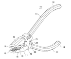
【解決手段】プライヤ10は、それぞれ先端側に顎部13,13を有し、それぞれ後端側にハンドル部14,14を有する一対のアーム11,11が連結軸12を介して回動可能に連結され、各顎部13,13間で対象物を挟持する。プライヤ10は、各顎部13,13の前方領域に複数の歯先によって先端側から見て外拡がりの台形状の凹部に形成され、これら凹部の各底面部及び各両側面部の前後方向に沿って複数の縦挟み歯15,15が形成されている。
【選択図】図1There is provided a plier that can securely clamp and remove a screw head even if the screw head is rusted and has a different outer diameter.
A pair of arms (11, 11) having jaw portions (13, 13) on the front end side and handle portions (14, 14) on the rear end side are rotatable via a connecting shaft (12). It is connected and the object is sandwiched between the jaws 13 and 13. The pliers 10 are formed in the front region of the jaws 13 and 13 into a trapezoidal recess that is outwardly spread when viewed from the tip side by a plurality of tooth tips, and along the front-rear direction of the bottom surface and the side surfaces of the recess. Thus, a plurality of vertical pinching teeth 15 are formed.
[Selection] Figure 1
Description
本考案は、顎部とハンドル部とが連結軸を介して連結されたプライヤに関する。 The present invention relates to a plier in which a jaw part and a handle part are connected via a connecting shaft.
従来、この種のプライヤは、例えば特許文献1に記載された技術がある。この技術は、対向して設けられた左顎部と右顎部からなる顎部を有している。この顎部の左顎部と右顎部との対接面の前部には、複数の縦挟み歯が設けられている。これらの縦挟み歯の歯先は、互いに同一の円弧面に配置されている。具体的には、上記縦挟み歯の歯先の上底は、同一の円弧曲面に配置されている。 Conventionally, this type of pliers has a technique described in Patent Document 1, for example. This technique has a jaw portion composed of a left jaw portion and a right jaw portion provided to face each other. A plurality of vertical pinching teeth are provided in the front part of the contact surface between the left jaw part and the right jaw part of the jaw part. The tips of these vertical pinching teeth are arranged on the same circular arc surface. Specifically, the upper base of the tip of the vertical pinch teeth is arranged on the same circular curved surface.
上記のように特許文献1に記載された技術では、縦挟み歯の歯先が同一の円弧面に配置されているため、円弧面の曲率と小ねじ(以下、単にビスという。)の頭部の外径の曲率が略同じであれば、接触面積が大きくなり、縦挟み歯の歯先で挟持する力が強くなる。 In the technique described in Patent Document 1 as described above, since the tips of the vertical pinching teeth are arranged on the same arc surface, the curvature of the arc surface and the head of a small screw (hereinafter simply referred to as a screw). If the curvatures of the outer diameters are substantially the same, the contact area is increased, and the force of clamping between the tips of the vertical pinching teeth is increased.
しかしながら、特許文献1に記載された技術では、縦挟み歯の円弧面の曲率に対してビス頭の外径の曲率が大きい場合、あるいは小さい場合には、縦挟み歯の歯先とビス頭の外周面が接触する接触面積が小さくなることから、縦挟み歯の歯先で挟持する力が極めて弱くなる。その結果、締結対象からビス頭を確実に挟持して取り外すことができないという問題がある。特に、ねじ軸が錆び付き、あるいはビス頭に設けた操作溝が変形して潰れた状態のビスにあっては、上記の問題が一段と顕著になる。 However, in the technique described in Patent Document 1, when the curvature of the outer diameter of the screw head is large or small with respect to the curvature of the arcuate surface of the vertical pinch tooth, the tip of the vertical pinch tooth and the screw head Since the contact area with which the outer peripheral surface comes into contact is reduced, the force of clamping with the tip of the vertical pinch teeth becomes extremely weak. As a result, there is a problem that the screw head cannot be securely clamped and removed from the fastening target. In particular, in the case of a screw in which the screw shaft is rusted or the operation groove provided on the screw head is deformed and crushed, the above problem becomes more remarkable.
本考案は、上記事情を考慮してなされたものであり、錆び付いて外径が異なるビス頭であっても、ビス頭を確実に挟持して取り外すことができるプライヤを提供することを目的とする。 The present invention has been made in consideration of the above circumstances, and an object of the present invention is to provide a plier that can securely nip and remove a screw head even if the screw head is rusted and has a different outer diameter. .
上記課題を解決するため、請求項1に記載の考案は、それぞれ先端側に顎部を有し、それぞれ後端側にハンドル部を有する一対のアームが連結軸を介して回動可能に連結され、前記各顎部間で対象物を挟持するプライヤであって、前記各顎部の前方領域に複数の歯先によって前記先端側から見て外拡がりの台形状の凹部に形成され、これら凹部の各底面部及び各両側面部の前後方向に沿って複数の縦挟み歯が形成されていることを特徴とする。 In order to solve the above-mentioned problems, the invention described in claim 1 is such that a pair of arms each having a jaw portion on the front end side and a handle portion on the rear end side are rotatably connected via a connecting shaft. A pliers for sandwiching an object between the jaws, and formed in a trapezoidal recess extending outwardly as viewed from the distal end side by a plurality of tooth tips in a front region of each jaw. A plurality of vertical pinching teeth are formed along the front-rear direction of each bottom surface portion and each side surface portion.
また、請求項2に記載の考案は、請求項1に記載の構成に加え、前記複数の縦挟み歯は、同一のピッチ及び高さで形成されていることを特徴とする。 Further, the invention described in claim 2 is characterized in that, in addition to the configuration described in claim 1, the plurality of vertical pinching teeth are formed at the same pitch and height.
また、請求項3に記載の考案は、請求項1又は2に記載の構成に加え、前記複数の縦挟み歯は、ピッチが1.50mm、高さが0.80mmに設定されていることを特徴とする。 In addition to the configuration according to claim 1 or 2, the invention described in claim 3 is that the plurality of vertical pinching teeth are set to have a pitch of 1.50 mm and a height of 0.80 mm. Features.
請求項1に記載の考案によれば、各顎部の前方領域に複数の歯先によって先端側から見て外拡がりの台形状の凹部に形成され、これら凹部の各底面部及び各両側面部の前後方向に沿って複数の縦挟み歯が形成されているので、錆び付いて外径が異なるビス頭であっても、縦挟み歯の歯先とビス頭が接触する接触面積が大きくなることから、ビス頭を確実に挟持して取り外すことができる。 According to the first aspect of the present invention, a plurality of tooth tips are formed in the front region of each jaw portion to form a trapezoidal concave portion that spreads outward as viewed from the distal end side, and each bottom surface portion and each side surface portion of the concave portion is Since a plurality of vertical pinching teeth are formed along the front-rear direction, even if it is a screw head that rusts and has a different outer diameter, the contact area between the vertical pinching tooth tip and the screw head increases, The screw head can be securely held and removed.
また、請求項2に記載の考案によれば、請求項1に記載の考案の効果に加え、複数の縦挟み歯は、同一のピッチ及び高さで形成されているので、縦挟み歯の歯先とビス頭が接触する接触面積がより大きくなることから、ビス頭を一段と確実に挟持して取り外すことができる。 According to the invention described in claim 2, in addition to the effect of the invention described in claim 1, since the plurality of vertical pinching teeth are formed with the same pitch and height, the teeth of the vertical pinching teeth Since the contact area where the tip and the screw head come into contact with each other is increased, the screw head can be more securely clamped and removed.
また、請求項3に記載の考案によれば、請求項1又は2に記載の考案の効果に加え、複数の縦挟み歯は、ピッチが1.50mm、高さが0.80mmに設定されているので、縦挟み歯の歯先とビス頭が接触する接触面積がさらに大きくなることから、ビス頭をさらに一段と確実に挟持して取り外すことができる。 According to the invention described in claim 3, in addition to the effects of the invention described in claim 1 or 2, the plurality of vertical pinching teeth are set to have a pitch of 1.50 mm and a height of 0.80 mm. As a result, the contact area where the tip of the vertically pinched teeth and the screw head come into contact with each other is further increased, so that the screw head can be more securely clamped and removed.
以下、本考案の実施形態について、図面を参照して詳細に説明する。 Hereinafter, embodiments of the present invention will be described in detail with reference to the drawings.
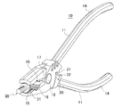
図1は、本考案の実施の形態に係るプライヤの構成を示す斜視図である。図2は、本実施の形態に係るプライヤにおいて顎部を閉じた状態を示す斜視図である。図3は、図2の縦断面図である。図4は、図2のプライヤを先端側から見た顎部を閉じた状態を示す正面図である。図5は、図4の顎部を示す拡大断面図である。 FIG. 1 is a perspective view showing a configuration of a plier according to an embodiment of the present invention. FIG. 2 is a perspective view showing a state in which the jaws are closed in the pliers according to the present embodiment. FIG. 3 is a longitudinal sectional view of FIG. FIG. 4 is a front view showing a state in which the jaw portion when the pliers of FIG. 2 are viewed from the distal end side is closed. FIG. 5 is an enlarged cross-sectional view showing the jaw part of FIG. 4.
なお、本実施の形態のプライヤでは、一対のアームにおいて顎部が設けられた側を先端側とし、ハンドル部が設けられた側を後端側として説明する。 In the pliers of the present embodiment, the side where the jaw portion is provided in the pair of arms will be described as the front end side, and the side where the handle portion is provided will be described as the rear end side.
図1〜図3に示すように、本実施の形態のプライヤ10は、一対のアーム11,11が連結軸12を介して回動可能に連結されている。一対のアーム11,11は、それぞれ先端側に顎部13,13を有し、それぞれ後端側にハンドル部14,14を有している。
As shown in FIGS. 1 to 3, the
各顎部13,13の対向面には、その先端側から連結軸12にかけてそれぞれ縦挟み歯15,15、横挟み歯16,16、及び切断刃17,17が順次形成されている。すなわち、各顎部13,13の対向面においては、前方領域にそれぞれ縦挟み歯15,15が配置され、中間領域にそれぞれ横挟み歯16,16が配置され、後方領域に切断刃17,17が配置されている。このように縦挟み歯15,15、横挟み歯16,16、及び切断刃17,17は、各顎部13,13の対向面に連続して形成されている。
On the opposing surfaces of the
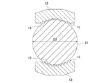
縦挟み歯15,15は、図1に示すように各顎部13,13の先端側からその長さ方向に沿って横挟み歯16,16までの前方領域において複数の歯が直線状に形成されている。縦挟み歯15,15の複数の歯先は、図4及び図5に示すようにそれぞれ先端側から見て外拡がりの台形状の凹部18,18に形成されている。すなわち、縦挟み歯15,15は、それぞれ先端側から見て歯先が外拡がりの台形状となるように分布しており、歯先の上底が同一の台形面に形成されている。縦挟み歯15,15は、後述するビス頭の外周面をビス締結面と直交する状態で挟持可能である。
As shown in FIG. 1, the
凹部18,18は、図5に示すように平坦状の底面部18a,18aと、この底面部18a,18aのそれぞれの両側に外拡がり状に形成された側面部18b,18b、側面部18b,18bと、を備える。これらの側面部18b,18b、側面部18b,18bは、それぞれ底面部18a,18aに対して緩やかな角度で傾斜している。
As shown in FIG. 5, the
底面部18a,18a、及び側面部18b,18b、側面部18b,18bには、それぞれ先端側から見て細かい多数の歯が左右方向へ山谷状に連続して形成されている。これらの細かい多数の歯は、同一のピッチで稠密に形成されている。具体的には、歯と歯の間のピッチは、1.50mmであって、歯の高さが0.80mmに設定されている。
The
横挟み歯16,16は、縦挟み歯15,15と切断刃17,17との間に、縦挟み歯15,15に直交する方向に設けられている。すなわち、横挟み歯16,16は、各顎部13,13の長さ方向に対して直交する方向に配置されている。横挟み歯16,16は、それぞれ歯先が円弧形凹溝となるように分布している。
The
切断刃17,17は、図3に示すように一対の対向刃であって、互いに対向する同一位置に半円状の小径皮むき孔17a,17aが形成されている。この小径皮むき孔17a,17aは、小径の絶縁電線を挟み込んで、その被覆部を剥ぎ取るために用いられる。
As shown in FIG. 3, the
一対のアーム11,11におけるハンドル部14,14側の連結軸12の近傍には、大径皮むき部20が設けられている。この大径皮むき部20は、小径皮むき孔17a,17aによって剥ぎ取る絶縁電線よりも大径の絶縁電線の被覆部を剥ぎ取るために用いられる。大径皮むき部20は、一方のアーム11に半円状に形成された凸部21が形成され、この凸部21に対向する他方のアーム11に円弧状に形成された凹部22が形成されている。
A large-diameter peeled
したがって、大径皮むき部20は、凸部21と凹部22との間に大径の絶縁電線を挟み込んで、その被覆部を剥ぎ取ることができる。なお、ハンドル部14,14には、それぞれ合成樹脂製のカバー14a,14aが被覆されている。
Therefore, the large-diameter
次に、本実施の形態のプライヤの作用を説明する。 Next, the operation of the pliers of this embodiment will be described.
図6は、本実施の形態に係るプライヤにおいて顎部でねじ頭を挟持した状態を示す斜視図である。図7は、図6の顎部で直径D1のねじ頭を挟持した状態を示す拡大断面図である。図8は、図6の顎部で直径D2のねじ頭を挟持した状態を示す拡大断面図である。 FIG. 6 is a perspective view showing a state in which the screw head is sandwiched between the jaws in the pliers according to the present embodiment. FIG. 7 is an enlarged cross-sectional view showing a state where a screw head having a diameter D1 is held between the jaws of FIG. FIG. 8 is an enlarged cross-sectional view showing a state where a screw head having a diameter D2 is held between the jaws of FIG.
プライヤ10の両アーム11,11のハンドル部14,14を握ると、図2〜図4に示すように顎部13,13の開く間隔が狭くなっていく。顎部13,13の間に、対象物がない場合、顎部13,13の先端部の縦挟み歯15,15の両側部同士が接触した時点で、顎部13,13が閉じた状態となる。この状態は、ハンドル部14,14が握り込み限界に達した状態である。この閉じた状態において、図3に示すように切断刃17,17の刃先が接触するとともに、一方のアーム11の凸部21が他方のアーム11の凹部22に空隙部を残して入り込む。
When the
そして、図6及び図7に示すように顎部13,13を開いて対象物としてのビス30の直径(外径)によってD1のビス頭31を挟持した場合、縦挟み歯15,15の凹部18の底面部18a,18aと、側面部18b,18b、側面部18b,18bの一部の歯を除くほとんどの歯がビス頭31を抱え込み、縦挟み歯15,15の各歯の先端がビス頭31の外周面に噛み込む。
6 and 7, when the
したがって、本実施の形態では、縦挟み歯15,15の歯先とビス頭31が接触する接触面積が大きくなることから、縦挟み歯15,15の歯先で挟持する力が極めて強くなる。その結果、プライヤ10の回転操作力をビス頭31に的確に伝達することができる。
Therefore, in the present embodiment, the contact area between the tooth tips of the vertical pinching
次に、図8に基づいて直径D1よりも大きな直径D2(D1<D2)のビス頭31を有するビス30を取り外す場合について説明する。
Next, the case where the
図8に示すように、顎部13,13を開いてビス30の直径がD2のビス頭31を挟持した場合、縦挟み歯15,15の底面部18a,18aと、側面部18b,18b、側面部18b,18bの略全ての歯がビス頭31を抱え込み、縦挟み歯15,15の各歯の先端がビス頭31の外周面に噛み込む。
As shown in FIG. 8, when the
本実施の形態では、直径D2の大きなビス頭31であっても、縦挟み歯15,15の歯先とビス頭31が接触する接触面積がさらに大きくなることから、縦挟み歯15,15の歯先で挟持する力が極めて強くなる。その結果、プライヤ10の回転操作力をビス頭31に一段と的確に伝達することができる。
In the present embodiment, even if the
ここで、本実施の形態のプライヤ10と、一般のプライヤとを比較する。一般のプライヤは、例えば縦挟み歯の複数の歯先が円弧面に配置されているものとする。これに対し、本実施の形態のプライヤ10は、上記のように縦挟み歯15,15の複数の歯先によって外拡がりの台形状の凹部18,18に形成されている。
Here, the
そのため、両者が同一ピッチ及び同一高さで歯を形成した場合、歯先を円弧面に配置したプライヤでは、ビス頭31の外径の大きさが変化することで、縦挟み歯で噛み込む歯数が極端に増減する。一方、外拡がりの台形状の凹部18,18に形成した本実施の形態のプライヤ10では、ビス頭31の外径の大きさが変化したとしても、縦挟み歯15,15で噛み込む歯数がさほど増減することなく、確実に挟持することができるようになった。
Therefore, when both teeth are formed with the same pitch and the same height, in the pliers in which the tooth tips are arranged on the circular arc surface, the outer diameter of the
したがって、本実施の形態のプライヤ10によれば、ビス頭31の直径が小さなビス30はもちろんのこと、直径が大きなビス30であっても、縦挟み歯15,15をビス頭31の外周面に食い込ませてビス頭31を的確に挟持することができる。これにより、ねじ軸が錆び付き、あるいは操作溝が変形して潰れた状態のビス30であっても、ビス頭31を的確に挟持し、緩み方向へ回転操作して、締結対象から確実に取り外すことができる。
Therefore, according to the
このように本実施の形態によれば、顎部13,13の前方領域に複数の歯先により先端側から見て外拡がりの台形状の凹部18,18に形成され、これら凹部18,18の各底面部18a,18a及び両側面部18b,18b、18b,18bにそれぞれ複数の縦挟み歯15,15が形成されているので、錆び付いて直径が異なるビス頭であっても、縦挟み歯15,15の歯先とビス頭31が接触する接触面積が大きくなることから、ビス頭31を確実に挟持して取り外すことができる。
As described above, according to the present embodiment, the front regions of the
また、本実施の形態によれば、複数の縦挟み歯15,15は、同一のピッチ及び高さで形成されているので、縦挟み歯15,15の歯先とビス頭31が接触する接触面積がさらに大きくなることから、ビス頭31を一段と確実に挟持して取り外すことができる。
Further, according to the present embodiment, since the plurality of vertical pinching
さらに、本実施の形態によれば、複数の縦挟み歯15,15は、ピッチが1.50mm、高さが0.80mmに設定されているので、上記と同様に縦挟み歯15,15の歯先とビス頭31が接触する接触面積がさらに大きくなることから、ビス頭31を一段と確実に挟持して取り外すことができる。
Furthermore, according to the present embodiment, the plurality of vertical pinching
なお、以上説明した実施の形態は、本考案の理解を容易にするために記載されたものであって、本考案を限定するために記載されたものではない。 The embodiments described above are described for facilitating understanding of the present invention, and are not described for limiting the present invention.
例えば、上記実施の形態のプライヤ10は、複数の縦挟み歯15,15のピッチが1.50mm、高さが0.80mmに設定した例について説明したが、これらの数値はあくまでも例示であって、対象物を確実に挟持できるのであれば、より細かいピッチであってもよい。
For example, in the
また、上記実施の形態のプライヤ10は、対象物としてビス30を締結対称から取り外す例について説明したが、これに限らず対象物としてその他のねじにも適用可能である。
Moreover, although the
10 プライヤ
11 アーム
12 連結軸
13 顎部
14 ハンドル部
14a カバー
15 縦挟み歯
16 横挟み歯
17 切断刃
17a 小径皮むき孔
18 凹部
18a 底面部
18b 側面部
20 大径皮むき部
21 凸部
22 凹部
30 ビス(対象物)
31 ビス頭
D1 直径
D2 直径
DESCRIPTION OF
31 Screw head D1 diameter D2 diameter
Claims (3)
前記各顎部の前方領域に複数の歯先によって前記先端側から見て外拡がりの台形状の凹部に形成され、これら凹部の各底面部及び各両側面部の前後方向に沿って複数の縦挟み歯が形成されていることを特徴とするプライヤ。 A pair of arms each having a jaw portion on the front end side and a pair of arms each having a handle portion on the rear end side are rotatably connected via a connecting shaft, and sandwich the object between the jaw portions. ,
The front region of each jaw is formed into a trapezoidal concave portion that spreads outward as viewed from the tip side by a plurality of tooth tips, and a plurality of vertical pinches along the front-rear direction of each bottom surface portion and each side surface portion of these concave portions A pliers characterized in that teeth are formed.
Priority Applications (1)
| Application Number | Priority Date | Filing Date | Title |
|---|---|---|---|
| JP2018004507U JP3219964U (en) | 2018-11-20 | 2018-11-20 | Pliers |
Applications Claiming Priority (1)
| Application Number | Priority Date | Filing Date | Title |
|---|---|---|---|
| JP2018004507U JP3219964U (en) | 2018-11-20 | 2018-11-20 | Pliers |
Publications (1)
| Publication Number | Publication Date |
|---|---|
| JP3219964U true JP3219964U (en) | 2019-01-31 |
Family
ID=65228750
Family Applications (1)
| Application Number | Title | Priority Date | Filing Date |
|---|---|---|---|
| JP2018004507U Active JP3219964U (en) | 2018-11-20 | 2018-11-20 | Pliers |
Country Status (1)
| Country | Link |
|---|---|
| JP (1) | JP3219964U (en) |
-
2018
- 2018-11-20 JP JP2018004507U patent/JP3219964U/en active Active
Similar Documents
| Publication | Publication Date | Title |
|---|---|---|
| JP5726365B1 (en) | Clamping tool | |
| US8656812B2 (en) | Plier | |
| JP3219964U (en) | Pliers | |
| TWI665056B (en) | Clamping tool | |
| JP2005279801A (en) | Prier | |
| TWI770103B (en) | wire stripper | |
| TWI807649B (en) | Pliers with angled crimping opening | |
| JP2019205219A (en) | Indirect live wire holding tool | |
| TWI312716B (en) | ||
| JP2018081813A (en) | Battery post terminal | |
| JP3221704U (en) | Clamping device | |
| JP2021178384A (en) | Hand tool | |
| JP6625715B1 (en) | Pliers | |
| JP2004330348A (en) | Pliers | |
| TWM600681U (en) | Pliers | |
| TWI718238B (en) | Pliers with two pliers legs | |
| TWM519572U (en) | Locking pliers | |
| JP3186586U (en) | Pliers with excellent cutting force | |
| US10411445B2 (en) | Clamping device | |
| CN211136837U (en) | Pliers | |
| JP3149145U (en) | Hammer with grooves for wire processing | |
| JP2008238316A (en) | Cutting tool | |
| TWM511135U (en) | Battery clamp | |
| JP6473432B2 (en) | Welding torch maintenance tool | |
| JP2021171912A (en) | Clamping tool |
Legal Events
| Date | Code | Title | Description |
|---|---|---|---|
| R150 | Certificate of patent or registration of utility model |
Ref document number: 3219964 Country of ref document: JP Free format text: JAPANESE INTERMEDIATE CODE: R150 |