JP3201836U - Lantern lighting device - Google Patents
Lantern lighting device Download PDFInfo
- Publication number
- JP3201836U JP3201836U JP2015005256U JP2015005256U JP3201836U JP 3201836 U JP3201836 U JP 3201836U JP 2015005256 U JP2015005256 U JP 2015005256U JP 2015005256 U JP2015005256 U JP 2015005256U JP 3201836 U JP3201836 U JP 3201836U
- Authority
- JP
- Japan
- Prior art keywords
- base
- connection
- illumination
- lantern
- members
- Prior art date
- Legal status (The legal status is an assumption and is not a legal conclusion. Google has not performed a legal analysis and makes no representation as to the accuracy of the status listed.)
- Active
Links
- 238000005286 illumination Methods 0.000 claims abstract description 79
- 230000017525 heat dissipation Effects 0.000 claims description 14
- 239000000758 substrate Substances 0.000 claims description 12
- 230000002093 peripheral effect Effects 0.000 abstract 1
- 238000010586 diagram Methods 0.000 description 2
- 230000000694 effects Effects 0.000 description 2
- 238000005452 bending Methods 0.000 description 1
- 238000001816 cooling Methods 0.000 description 1
- 239000007858 starting material Substances 0.000 description 1
Images


Abstract
【課題】それぞれ簡単に交換できる複数の筒状照明部材を環設してなるランタン状照明用装置を提供する。【解決手段】口金部材1と、第一基部2と、第二基部3と、複数の連結棒4と、複数の接続手段5とを備え、第一基部2および第二基部3は、それぞれ複数の連結棒4の両端に連結され、口金部材1は、第一基部2における複数の連結棒4の反対側に連結され、複数の接続手段5の何れも、第一接続部材51と、第二接続部材52とを有し、第一接続部材51は、第一基部2における第二基部3に面する表面の周縁にリング状に配置されると共に、第二接続部材52は、第二基部3における第一基部2に面する表面の周縁にリング状に配置され、第一基部2および第二基部3は、対向に設置され、複数の接続手段5が口金部材1と並列に電気接続される。【選択図】図1A lantern-shaped illumination device is provided that includes a plurality of cylindrical illumination members that can be easily replaced. A base member, a first base portion, a second base portion, a plurality of connecting rods, and a plurality of connecting means are provided, each of which includes a plurality of first base portions and a plurality of second base portions. The base member 1 is connected to the opposite side of the plurality of connecting rods 4 in the first base 2, and any of the plurality of connecting means 5 is connected to the first connecting member 51 and the second connecting rod 4. The first connection member 51 is arranged in a ring shape on the peripheral edge of the surface facing the second base 3 in the first base 2, and the second connection member 52 is connected to the second base 3. The first base 2 and the second base 3 are arranged opposite to each other at the periphery of the surface facing the first base 2, and the plurality of connection means 5 are electrically connected in parallel with the base member 1. . [Selection] Figure 1
Description
本考案は、特にそれぞれの筒状照明部材を容易に交換できるように環設される複数の筒状照明部材を保持するランタン状照明用装置に関するものである。 In particular, the present invention relates to a lantern-shaped illumination device that holds a plurality of tubular illumination members that are provided so that the respective tubular illumination members can be easily replaced.
従来の360度方向照射式ランタン状照明装置は、360度方向への照射を可能にするように、発光管を折り曲げるなどの形態で、照明部材の形状を改変するものである。例えばスパイラル型照明部材、またはトリプルU形照明部材などを用いるランタン状照明装置が提案される。 The conventional 360 degree direction irradiation type lantern-shaped illuminating device modifies the shape of the illumination member by bending the arc tube so as to enable irradiation in the 360 degree direction. For example, a lantern-shaped illumination device using a spiral illumination member or a triple U-shaped illumination member is proposed.
しかしながら、前記従来のランタン状照明装置の照明部材が故障しても、故障の照明部材を容易に交換することができないことから、使用者は高いコストを負担することになってしまう。また、従来の照明装置の放熱構成は、照明部材の内部の照明素子を対象とするものであり、同時に照明部材自体の放熱に寄与することができないので、照明部材が高温にさらされる状態で使用され、照明部材の寿命が短縮してしまう。 However, even if the illumination member of the conventional lantern-shaped illumination device breaks down, the failed illumination member cannot be easily replaced, so that the user bears a high cost. Also, the heat dissipation structure of the conventional lighting device is intended for the lighting element inside the lighting member, and at the same time cannot contribute to the heat dissipation of the lighting member itself, so it is used in a state where the lighting member is exposed to high temperature As a result, the life of the illumination member is shortened.
そこで、案出されたのが本考案であって、環設される複数の筒状照明部材を保持するランタン状照明用装置を提供することを目的としている。 Accordingly, the present invention has been devised, and an object thereof is to provide a lantern-like illumination device that holds a plurality of annular illumination members that are provided in a ring.
本願の請求項1の考案は、口金部材1と、第一基部2と、第二基部3と、複数の連結棒4と、複数の接続手段5とを備え、
前記第一基部2および第二基部3は、それぞれ前記複数の連結棒4の両端に連結され、
前記口金部材1は、前記第一基部2における該複数の連結棒4の反対側に連結され、
前記複数の接続手段5の何れも、第一接続部材51と、第二接続部材52とを有し、該複数の接続手段5の複数の第一接続部材51は、該第一基部2における前記第二基部3に面する表面の周縁にリング状に配置されると共に、該複数の接続手段5の複数の第二接続部材52は、該第二基部3における前記第一基部2に面する表面の周縁にリング状に配置され、該第一基部2および第二基部3は、対向に設置され、前記複数の接続手段5が前記口金部材1と並列に電気接続されることを特徴とするランタン状照明用装置、を提供する。
The invention of claim 1 of the present application comprises a base member 1, a first base 2, a
The first base 2 and the
The base member 1 is connected to the opposite side of the plurality of connecting rods 4 in the first base 2,
Each of the plurality of connection means 5 includes a
本願の請求項2の考案は、前記第一基部2と第二基部3との間に設置される放熱手段7と、
それぞれ前記複数の接続手段5における第一接続部材51と第二接続部材52との間に接続され、リング状に配置されると共に、前記放熱手段7を囲む複数の照明部材6とを有することを特徴とする請求項1に記載のランタン状照明用装置、を提供する。
The invention of claim 2 of the present application includes a heat dissipating means 7 installed between the first base 2 and the
Each of the plurality of connection means 5 includes a plurality of
本願の請求項3の考案は、前記放熱手段7は、複数の連結ロッド71と、ファン72とを有し、
該複数の連結ロッド71の一端は、前記第二基部3における前記第一基部2に面する表面に連結され、
該ファン72は、前記複数の連結ロッド71における該第二基部3の反対端に連結されると共に、前記第一基部2と第二基部3との間に位置することを特徴とする請求項2に記載のランタン状照明用装置、を提供する。
In the invention of
One ends of the plurality of connecting
The
本考案のランタン状照明用装置は、複数の筒状照明部材を環状に配置させるものであるので、環状に配置された複数の筒状照明部材により、360度方向へ照射することができる。また、該複数の筒状照明部材が並列に接続され、一部の照明部材が故障する場合でも、ほかの照明部材は使用不能にはならない。さらに、故障した照明部材を容易に交換することができる。よって、使用者が負担するコストの低減を図ることができる。 Since the lantern-shaped illumination device of the present invention has a plurality of cylindrical illumination members arranged in a ring shape, it can be irradiated in a 360-degree direction by the plurality of cylindrical illumination members arranged in a ring shape. Further, even when the plurality of tubular illumination members are connected in parallel and some of the illumination members fail, other illumination members are not disabled. Furthermore, the failed lighting member can be easily replaced. Therefore, the cost borne by the user can be reduced.
さらに、複数の筒状照明部材が放熱手段の周囲に配置されることから、該放熱手段で同時に該複数の筒状照明部材の放熱を促進し、該複数の筒状照明部材の温度を下げ、その寿命の増大を図ることができる。 Further, since the plurality of cylindrical illumination members are arranged around the heat dissipation means, the heat dissipation means simultaneously promotes heat dissipation of the plurality of cylindrical illumination members, and reduces the temperature of the plurality of cylindrical illumination members, The lifetime can be increased.
以下、添付図面を参照して本考案の好適な実施の形態を詳細に説明する。 Hereinafter, preferred embodiments of the present invention will be described in detail with reference to the accompanying drawings.
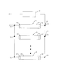
図1ないし図5に示すように、本考案に係るランタン状照明用装置の第一実施例は、口金部材1と、第一基部2と、第二基部3と、複数の連結棒4と、複数の接続手段5と、複数の照明部材6と、放熱手段7とを備える。
As shown in FIGS. 1 to 5, the first embodiment of the lantern-shaped illumination device according to the present invention includes a base member 1, a first base portion 2, a
前記口金部材1は、連結座11と、該連結座11の一端に連結される、外部電源を接続するための口金本体12とを備える。
前記第一基部2および第二基部3は、それぞれプレート状を呈するものである。前記複数の連結棒4は、前記第一基部2と第二基部3との間に、間隔を開けて配置される。前記第一基部2および第二基部3は、固定部材8により、それぞれ前記複数の連結棒4の両端に連結される。また、前記口金部材1の連結座11は、前記第一基部2における該複数の連結棒4の反対側に連結される。
The base member 1 includes a connecting
The first base 2 and the
また、該第二基部3の底面における中央部に複数の発光素子(図示せず)が設けられることが好ましい。前記該第二基部3の底面における中央部に設けられる複数の発光素子により、本考案に係るランタン状照明用装置の下方へ光線を照射することができるので、本考案の照射範囲をさらに拡大することができる。
In addition, it is preferable that a plurality of light emitting elements (not shown) are provided at the center of the bottom surface of the
前記複数の接続手段5の何れも、第一接続部材51と、第二接続部材52とを有する。該複数の接続手段5の複数の第一接続部材51は、該第一基部2における前記第二基部3に面する表面の周縁にリング状に配置されると共に、該第一基部2に固定される。該複数の接続手段5の複数の第二接続部材52は、該第二基部3における前記第一基部2に面する表面の周縁にリング状に配置されると共に、該第二基部3に固定される。該第一基部2および第二基部3は、対向に設置される。また、本実施例において、該第一接続部材51および第二接続部材52は共に回転固定方式で照明部材6を保持するものである。
Each of the plurality of connection means 5 includes a
各照明部材6は、本体61と、該本体61の両端にそれぞれ設けられる二つの電気接続端子62とを有する。該複数の接続手段5の複数の第一接続部材51及び第二接続部材52は、それぞれ前記複数の照明部材6の二つの電気接続端子62を挿入させる。二つの電気接続端子62がそれぞれ前記第一接続部材51及び第二接続部材52に挿入した照明部材6の本体61を回転させると、該二つの電気接続端子62はそれぞれ前記第一接続部材51及び第二接続部材52に電気接続される。図5に示すように、各接続手段5の第一接続部材51は、該複数の照明部材6がそれぞれ前記口金部材1の口金本体12と並列回路を構成するために、それぞれ前記口金部材1の口金本体12に繋がる。これにより、前記複数の接続手段5の第一接続部材51を介して、該複数の照明部材6に対して、シングルサイド給電することができる。本実施例において、該照明部材6は、T5型、T8型、T9型またはT10型など、電源内蔵の直管形照明部材であることが好ましい。
Each
前記放熱手段7は、複数の連結ロッド71と、ファン72とを有する。該複数の連結ロッド71の一端は、前記第二基部3における前記第一基部2に面する表面に連結される。該ファン72は、前記複数の連結ロッド71における該第二基部3の反対端に連結されると共に、前記第一基部2と第二基部3との間に位置する。また、前記複数の照明部材6は、該ファン72を囲むように、リング状に配置される。
The heat dissipation means 7 includes a plurality of connecting
本考案に係るランタン状照明用装置の使用状態において、各照明部材6の両端の電気接続端子62は、それぞれ前記第一接続部材51及び第二接続部材52に挿入され、該照明部材6を回転させることで、該電気接続端子62は、それぞれ前記第一接続部材51及び第二接続部材52に電気接続される。前記複数の第一接続部材51を介して、該複数の照明部材6は、それぞれ前記口金部材1の口金本体12と並列回路を構成する。また、該複数の照明部材6は、360度方向へ照射することができるように、リング状に配置される。前記第一基部2と第二基部3との間に、放熱手段7が設置され、該放熱手段7のファン72は、リング状に配置されると共に、360度方向へ照射することができる前記複数の照明部材6に囲まれる。前記口金部材1の口金本体12と外部電源とが電気接続されると、該複数の照明部材6は点灯し、光線を360度方向へ照射することができる。同時に、該放熱手段7のファン72は、該複数の照明部材6の動作により加熱された空気を交換させ、該複数の照明部材6を冷却させる。具体的に、図4に示すように、前記複数の照明部材6は、間隔をおいて配置されているものであるので、該ファン72の稼働により、照明部材6同士の間から、本考案に係るランタン状照明用装置の内部に流入する外部の低温度空気で、該複数の照明部材6の動作により加熱された空気が交換されるので、該複数の照明部材6に対する冷却効果を齎すことに寄与する。
In the use state of the lantern-shaped illumination device according to the present invention, the
図6に示すように、ほかの回路実施形態として、各接続手段5の第一接続部材51および第二接続部材52は、前記口金部材1の口金本体12と並列回路を構成するものである。これにより、前記複数の接続手段5の第一接続部材51および第二接続部材52を介して、該複数の照明部材6に対して、ダブルサイド給電することができる。また、この実施形態では、スターター内蔵のT8型の直管形発光ダイオードランプが照明部材6として用いられている。この直管形発光ダイオードランプは、正面と背面とを有する直尺基板と、該直尺基板の正面に設けられる複数の発光ダイオード素子と、該複数の発光ダイオード素子を被覆するように該直尺基板の正面に設けられ、該直尺基板の長手方向に延在する透明カバーと、該直尺基板の背面に設けられ、該直尺基板の長手方向に延在すると共に、該発光ダイオード素子からの熱量を放熱するヒートシンクと、該直尺基板に電気接続され、それぞれ前記複数の接続手段5の第一接続部材51および第二接続部材52に電気接続し得る構成を有すると共に、前記直尺基板および発光ダイオード素子を前記透明カバーと前記ヒートシンクとに保持するように、前記透明カバーと前記ヒートシンクと結合される二つの口金と、を備える。本実施形態では、前記複数の照明部材6として用いられた複数の直管形発光ダイオードランプは、それぞれのヒートシンクが前記放熱手段7に面するように配置される。よって、該放熱手段7のファン72により駆動される空気の流れは、前記ヒートシンクの熱交換を促進するので、放熱効果をさらに向上させることができる。
As shown in FIG. 6, as another circuit embodiment, the
図7及び図8に示すように、本考案に係るランタン状照明用装置の第二実施例は、前記第一実施例とほぼ同様のものであるが、以下の点で異なる。前記第一実施例で用いられたのは、回転固定方式で照明部材6を保持する第一接続部材51および第二接続部材52を有する接続手段5であるが、この実施例において、押圧固定方式で照明部材6を保持する第一接続部材51’および第二接続部材52’を有する接続手段5’が用いられている。前記複数の照明部材6の二つの電気接続端子62は、それぞれ前記複数の接続手段5’における第一接続部材51’及び第二接続部材52’の穴挿入されると共に、該第一接続部材51’及び第二接続部材52’に当接されるので、前記複数の照明部材6はそれぞれ前記複数の接続手段5’の第一接続部材51’及び第二接続部材52’と電気接続される。
As shown in FIGS. 7 and 8, the second embodiment of the lantern-shaped illumination device according to the present invention is substantially the same as the first embodiment, but differs in the following points. What is used in the first embodiment is the connection means 5 having the
本考案は上記の構成を有するので、第一基部2と、第二基部3と前記環状に配置された複数の筒状照明部材により、360度方向への照射を可能にする。また、該複数の筒状照明部材が並列に接続され、故障した照明部材を容易に交換することができる。さらに、複数の筒状照明部材が放熱手段の周囲に配置されることから、該放熱手段で同時に該複数の筒状照明部材の放熱を促進し、該複数の筒状照明部材の温度を下げ、その寿命を増大することができる。
Since the present invention has the above-described configuration, the first base portion 2, the
1 口金部材
11 連結座
12 口金本体
2 第一基部
3 第二基部
4 連結棒
5、5’ 接続手段
51、51’ 第一接続部材
52、52’ 第二接続部材
6 照明部材
61 本体
62 電気接続端子
7 放熱手段
71 連結ロッド
72 ファン
8 固定部材
DESCRIPTION OF SYMBOLS 1
Claims (4)
前記第一基部2および第二基部3は、それぞれ前記複数の連結棒4の両端に連結され、
前記口金部材1は、前記第一基部2における該複数の連結棒4の反対側に連結され、
前記複数の接続手段5の何れも、第一接続部材51と、第二接続部材52とを有し、該複数の接続手段5の複数の第一接続部材51は、該第一基部2における前記第二基部3に面する表面の周縁にリング状に配置されると共に、該複数の接続手段5の複数の第二接続部材52は、該第二基部3における前記第一基部2に面する表面の周縁にリング状に配置され、該第一基部2および第二基部3は、対向に設置され、前記複数の接続手段5が前記口金部材1と並列に電気接続されることを特徴とするランタン状照明用装置。 A base member 1, a first base 2, a second base 3, a plurality of connecting rods 4, and a plurality of connecting means 5,
The first base 2 and the second base 3 are respectively connected to both ends of the plurality of connecting rods 4,
The base member 1 is connected to the opposite side of the plurality of connecting rods 4 in the first base 2,
Each of the plurality of connection means 5 includes a first connection member 51 and a second connection member 52, and the plurality of first connection members 51 of the plurality of connection means 5 are arranged in the first base 2. A plurality of second connection members 52 of the plurality of connecting means 5 are arranged on the periphery of the surface facing the second base 3 and the surface facing the first base 2 in the second base 3 The lantern is characterized in that the first base 2 and the second base 3 are arranged opposite to each other, and the plurality of connecting means 5 are electrically connected in parallel with the base member 1. -Like lighting device.
それぞれ前記複数の接続手段5における第一接続部材51と第二接続部材52との間に接続され、リング状に配置されると共に、前記放熱手段7を囲む複数の照明部材6とを有することを特徴とする請求項1に記載のランタン状照明用装置。 Heat radiating means 7 installed between the first base 2 and the second base 3;
Each of the plurality of connection means 5 includes a plurality of illumination members 6 connected between the first connection member 51 and the second connection member 52, arranged in a ring shape, and surrounding the heat dissipation means 7. The lantern-shaped illumination device according to claim 1, wherein the device is a lantern-shaped illumination device.
該複数の連結ロッド71の一端は、前記第二基部3における前記第一基部2に面する表面に連結され、
該ファン72は、前記複数の連結ロッド71における該第二基部3の反対端に連結されると共に、前記第一基部2と第二基部3との間に位置することを特徴とする請求項2に記載のランタン状照明用装置。 The heat dissipation means 7 has a plurality of connecting rods 71 and a fan 72,
One ends of the plurality of connecting rods 71 are connected to the surface of the second base 3 facing the first base 2,
The fan 72 is connected to an opposite end of the second base portion 3 of the plurality of connecting rods 71 and is positioned between the first base portion 2 and the second base portion 3. A lantern-shaped illumination device according to claim 1.
前記複数の照明部材6は、それぞれのヒートシンクが前記放熱手段7に面するように配置されることを特徴とする請求項2または請求項3に記載のランタン状照明用装置。 The plurality of illumination members 6 includes a straight substrate having a front surface and a back surface, a plurality of light emitting diode elements provided on the front surface of the straight substrate, and the straight substrate so as to cover the plurality of light emitting diode elements. A transparent cover extending in the longitudinal direction of the linear substrate, and provided on the back surface of the linear substrate, extending in the longitudinal direction of the linear substrate, and extending from the light emitting diode element. A heat sink that dissipates heat, and a structure that can be electrically connected to the first connection member 51 and the second connection member 52 of the plurality of connection means 5, respectively, Two caps coupled to the transparent cover and the heat sink so as to hold the light emitting diode element on the transparent cover and the heat sink;
The lantern-shaped illumination device according to claim 2, wherein the plurality of illumination members 6 are arranged such that each heat sink faces the heat radiating means 7.
Priority Applications (1)
| Application Number | Priority Date | Filing Date | Title |
|---|---|---|---|
| JP2015005256U JP3201836U (en) | 2015-10-17 | 2015-10-17 | Lantern lighting device |
Applications Claiming Priority (1)
| Application Number | Priority Date | Filing Date | Title |
|---|---|---|---|
| JP2015005256U JP3201836U (en) | 2015-10-17 | 2015-10-17 | Lantern lighting device |
Publications (1)
| Publication Number | Publication Date |
|---|---|
| JP3201836U true JP3201836U (en) | 2016-01-07 |
Family
ID=55069381
Family Applications (1)
| Application Number | Title | Priority Date | Filing Date |
|---|---|---|---|
| JP2015005256U Active JP3201836U (en) | 2015-10-17 | 2015-10-17 | Lantern lighting device |
Country Status (1)
| Country | Link |
|---|---|
| JP (1) | JP3201836U (en) |
-
2015
- 2015-10-17 JP JP2015005256U patent/JP3201836U/en active Active
Similar Documents
| Publication | Publication Date | Title |
|---|---|---|
| KR101253199B1 (en) | Lighting apparatus | |
| KR101227527B1 (en) | Lighting apparatus | |
| JP5499475B2 (en) | Lamp device and lighting device | |
| KR101349843B1 (en) | Lighting apparatus | |
| KR20140038116A (en) | Led lamp | |
| KR101295281B1 (en) | Lighting apparatus | |
| JP3164034U (en) | LED lighting device | |
| JP5835815B2 (en) | Apparatus, method and system for modular light emitting diode circuit assembly | |
| TW201425811A (en) | Solid-state illuminator with air passage | |
| JP2014154230A (en) | Lamp device, light-emitting device, and lighting device | |
| JP2013239253A (en) | Bulb-type lamp and lighting fixture | |
| JP3163443U (en) | LED lighting device | |
| JP2015153639A (en) | Lighting device using led lamp | |
| US20070090386A1 (en) | Air cooled high-efficiency light emitting diode spotlight or floodlight | |
| JP3201836U (en) | Lantern lighting device | |
| KR102047686B1 (en) | Lighting apparatus | |
| JP2013143397A (en) | Led light source device | |
| JP6331877B2 (en) | lamp | |
| WO2016031370A1 (en) | Lamp | |
| KR101202406B1 (en) | Lighting device of LED | |
| JP2012038695A (en) | Led bulb for lighting with high heat radiation effect | |
| JP2011076905A (en) | Led lamp | |
| JP6172460B2 (en) | Lamp device, socket and lighting device | |
| JP6331876B2 (en) | lamp | |
| JP2006244726A (en) | Led lighting system |
Legal Events
| Date | Code | Title | Description |
|---|---|---|---|
| R150 | Certificate of patent or registration of utility model |
Ref document number: 3201836 Country of ref document: JP Free format text: JAPANESE INTERMEDIATE CODE: R150 |
|
| R250 | Receipt of annual fees |
Free format text: JAPANESE INTERMEDIATE CODE: R250 |
|
| R250 | Receipt of annual fees |
Free format text: JAPANESE INTERMEDIATE CODE: R250 |
|
| R250 | Receipt of annual fees |
Free format text: JAPANESE INTERMEDIATE CODE: R250 |
|
| R250 | Receipt of annual fees |
Free format text: JAPANESE INTERMEDIATE CODE: R250 |
|
| R250 | Receipt of annual fees |
Free format text: JAPANESE INTERMEDIATE CODE: R250 |
|
| R250 | Receipt of annual fees |
Free format text: JAPANESE INTERMEDIATE CODE: R250 |