JP3189404U - Joint box - Google Patents
Joint box Download PDFInfo
- Publication number
- JP3189404U JP3189404U JP2013007310U JP2013007310U JP3189404U JP 3189404 U JP3189404 U JP 3189404U JP 2013007310 U JP2013007310 U JP 2013007310U JP 2013007310 U JP2013007310 U JP 2013007310U JP 3189404 U JP3189404 U JP 3189404U
- Authority
- JP
- Japan
- Prior art keywords
- valve body
- joint box
- peripheral wall
- bundle
- frame
- Prior art date
- Legal status (The legal status is an assumption and is not a legal conclusion. Google has not performed a legal analysis and makes no representation as to the accuracy of the status listed.)
- Ceased
Links
- 230000002093 peripheral Effects 0.000 claims abstract description 77
- 238000003780 insertion Methods 0.000 claims description 6
- 230000000149 penetrating Effects 0.000 claims description 2
- 239000000463 material Substances 0.000 description 7
- 238000009413 insulation Methods 0.000 description 6
- 239000004035 construction material Substances 0.000 description 4
- 238000009429 electrical wiring Methods 0.000 description 4
- XEEYBQQBJWHFJM-UHFFFAOYSA-N iron Chemical compound [Fe] XEEYBQQBJWHFJM-UHFFFAOYSA-N 0.000 description 4
- 238000000034 method Methods 0.000 description 4
- 239000000203 mixture Substances 0.000 description 4
- 230000004308 accommodation Effects 0.000 description 2
- 238000005452 bending Methods 0.000 description 2
- 229910052742 iron Inorganic materials 0.000 description 2
- 238000004519 manufacturing process Methods 0.000 description 2
- 238000000465 moulding Methods 0.000 description 2
- -1 polypropylene Polymers 0.000 description 2
- 239000000725 suspension Substances 0.000 description 2
- 229920003002 synthetic resin Polymers 0.000 description 2
- 239000000057 synthetic resin Substances 0.000 description 2
- 239000004698 Polyethylene (PE) Substances 0.000 description 1
- 239000004743 Polypropylene Substances 0.000 description 1
- 230000000903 blocking Effects 0.000 description 1
- 238000005516 engineering process Methods 0.000 description 1
- 238000007689 inspection Methods 0.000 description 1
- 230000004048 modification Effects 0.000 description 1
- 238000006011 modification reaction Methods 0.000 description 1
- 229920000573 polyethylene Polymers 0.000 description 1
- 229920001155 polypropylene Polymers 0.000 description 1
- 238000009420 retrofitting Methods 0.000 description 1
- 239000007779 soft material Substances 0.000 description 1
Images


Abstract
【課題】多くの電線を束ねて処理しても容易に被せることができ、また、容易に取り外すことができるジョイントボックスを提供する。
【解決手段】ジョイントボックス1Aは、長手方向に対する垂直断面が多角形の形状に形成された周壁3と、周壁の一方の端部を覆うように連結された端面部材4と、周壁の他方の端部に連結されて、周壁及び端面部材で囲まれる収容空間に結線束を挿入するための開口部を開口可能なように覆う第一弁体21及び第二弁体群20と、周壁における多角形の形状に相似させ、かつ、周壁の他方の端部側の外形サイズと同一またはそれよりも大きく形成されて第一弁体及び第二弁体群が内周側に周設される枠体10を有する台座2Aと、を備える。
【選択図】図1Provided is a joint box that can be easily covered even if many electric wires are bundled and processed and can be easily removed.
A joint box 1A includes a peripheral wall 3 having a polygonal cross section perpendicular to the longitudinal direction, an end face member 4 connected so as to cover one end of the peripheral wall, and the other end of the peripheral wall. The first valve body 21 and the second valve body group 20 that are connected to the part and cover the opening for inserting the wire bundle in the accommodating space surrounded by the peripheral wall and the end face member, and the polygon on the peripheral wall And a frame body 10 that is formed to be equal to or larger than the outer size of the other end side of the peripheral wall and in which the first valve body and the second valve body group are provided on the inner peripheral side. And a pedestal 2 </ b> A.
[Selection] Figure 1
Description
本考案は、先端相互が結束された複数の電線を束ねて処理される結線束を絶縁保護する為のジョイントボックスに関する。 The present invention relates to a joint box for insulating and protecting a bundle of bundles that are processed by bundling a plurality of electric wires whose ends are bound together.
屋内電気配線工事において、先端相互が結束された複数の電線を束ねて処理される結線束に、絶縁保護する為のジョイントボックスを被せている。 In indoor electrical wiring work, a joint bundle for insulating protection is put on a bundle of wires that is processed by bundling a plurality of electric wires whose ends are bound together.
なお、内側には、複数の電線の先端相互を結束して成る結線束を挿入する為の空間を備え、かつ一面には結線束を内部空間に挿入する為の口開部を有する電気配線用ジョイントボックスにおいて、ボックスの内周壁から中央部に向けて、複数の電線先端相互の結線束に係合させて結線束からボックスが抜脱するのを防ぐ為の複数の弁体を伸長させ、しかも弁体には結線束を口開部から内部空間に押込み挿入する場合は弾力的に曲がってその挿入を許容し、ボックスの全自重に相当する力では結線束の通過を阻止するような弾力性を備えさせたものが知られている(例えば、特許文献1を参照)。 In addition, the inside has a space for inserting a wire bundle formed by bundling the ends of a plurality of electric wires, and one side has an opening for inserting the wire bundle into the internal space. In the joint box, from the inner peripheral wall of the box toward the center, it engages with the connection bundle between the ends of the wires and extends a plurality of valve bodies to prevent the box from being pulled out of the connection bundle. The valve body is elastic enough to bend and insert the connection bundle into the internal space from the mouth opening, allowing it to be inserted, and blocking the connection bundle with a force equivalent to the total weight of the box. Is known (see, for example, Patent Document 1).
前述した技術等によるジョイントボックスでは、多くの電線を処理してジョイントボックスを被せる作業において、その開口部を覆おう弁体に電線やコネクタ等が引っかかり挿入し難く、作業に手間がかかるという課題があった。また、保守等の際に、ジョイントボックスを電線から取り外すと、弁体の根元から破損し易いなどの課題があった。 In the joint box by the above-described technology, in the work of processing a lot of electric wires and covering the joint box, there is a problem that it is difficult to insert the electric wire or the connector on the valve body covering the opening, and the work is troublesome. there were. Further, when the joint box is removed from the electric wire during maintenance, there is a problem that the valve body is easily damaged.
本考案が解決しようとする課題は、多くの電線を束ねて処理しても容易に被ることができ、また、容易に取り外すことができるジョイントボックスを提供することである。 The problem to be solved by the present invention is to provide a joint box that can be easily covered even when many electric wires are bundled and processed and can be easily removed.
上記課題を解決するために、本考案に係るジョイントボックスは、先端相互が結束された複数の電線を束ねて処理される結線束に被せて絶縁保護するためのジョイントボックスである。当該ジョイントボックスは、前記結線束の頭部の周囲を囲むように位置させる、当該ジョイントボックスの長手方向に対する垂直断面が多角形の形状に形成された周壁と、前記結線束の頭部を覆うように位置させると共に前記周壁の一方の端部を覆うように連結された端面部材と、前記周壁の他方の端部に連結されて、前記周壁及び前記端面部材で囲まれる収容空間に前記結線束の頭部を前記端面部材の方向に向けて挿入可能な開口部が設けられ、前記開口部を開口可能なように覆う第一弁体及び第二弁体と、前記周壁における前記多角形の形状に相似させ、かつ、前記周壁の他方の端部側の外形のサイズと同一またはそれよりも大きく形成されて前記第一弁体及び第二弁体が内周側に周設される枠体とを有する台座と、を備えている。前記第一弁体は、板状が伸びきった状態において、前記枠体の前記内周側に対向する一組の辺に各々を一辺又は各々を分割した辺を一辺とする略四角形の板状とされ、当該略四角形の板状の長手方向に沿ってその先端部から切り込み又は二股構造を有し、前記第二弁体は、前記一組の辺以外の前記内周側の他の辺の各々を底辺又は各々を分割した辺を底辺とする略三角形の板状とされ、当該略三角形の板状の前記台座の中央部に向く先端部が丸みを帯びるように形成され、複数の前記第一弁体及び第二弁体の隣り合う各々が、間隔を設けて前記台座の中央部に向く状態で周設されて、前記第一弁体及び第二弁体は、前記結線束を前記周壁及び前記端面部材で囲まれる収容空間に挿入する場合においては当該挿入を許容し、さらに、前記結線束に対して当該ジョイントボックスを被せ付けた後の場合においては当該ジョイントボックスの自重によって当該ジョイントボックスが抜脱しない弾力性を有することを特徴とする。 In order to solve the above-described problems, a joint box according to the present invention is a joint box for insulating protection by covering a bundle of wires which are processed by bundling a plurality of electric wires whose ends are bound together. The joint box is positioned so as to surround the periphery of the head of the connection bundle, and covers the peripheral wall formed in a polygonal shape with respect to the longitudinal direction of the joint box, and the head of the connection bundle. An end face member connected to cover one end of the peripheral wall and the other end of the peripheral wall, and the connection bundle is connected to the housing space surrounded by the peripheral wall and the end face member. An opening that can be inserted with the head directed in the direction of the end face member is provided, and the first valve body and the second valve body that cover the opening so as to be openable, and the polygonal shape in the peripheral wall A frame body that is similar and is formed to be equal to or larger than the size of the outer shape on the other end side of the peripheral wall, and the first valve body and the second valve body are provided around the inner peripheral side. And a pedestal having the same. The first valve body has a substantially rectangular plate shape in which one side is divided into a set of sides facing the inner peripheral side of the frame body or a side obtained by dividing each side in a state where the plate shape is fully extended. And has a notch or bifurcated structure along the substantially rectangular plate-like longitudinal direction, and the second valve body is formed on the other side of the inner peripheral side other than the set of sides. Each plate has a substantially triangular plate shape with each of the bases or a divided side as a base, and a tip portion facing the center of the substantially triangular plate-like pedestal is rounded. Each adjacent one of the one valve body and the second valve body is circumferentially provided in a state facing the central portion of the pedestal, and the first valve body and the second valve body connect the wire bundle to the peripheral wall. And insertion in the housing space surrounded by the end face member, the insertion is allowed, and the wire bundle The joint box is characterized by having a resilient not pulled out by the weight of the joint box in the case of after applying covered the joint box for.
本考案に係るジョイントボックスによれば、多くの電線を束ねて処理しても容易に被ることができ、また、容易に取り外すことができる。 According to the joint box according to the present invention, even if many electric wires are bundled and processed, they can be easily covered, and can be easily removed.
以下、本考案に係る実施形態のジョイントボックスについて、図面を参照して具体的に説明する。ここで、互いに同一または類似の部分には共通の符号を付して、重複説明は省略する。ここで説明する下記の実施形態はいずれも、屋内電気配線工事の一例をとりあげて説明する。 Hereinafter, a joint box according to an embodiment of the present invention will be specifically described with reference to the drawings. Here, the same or similar parts are denoted by common reference numerals, and redundant description is omitted. Each of the following embodiments described here will be described by taking an example of indoor electrical wiring work.
[第1の実施形態]
以下、本考案に係るジョイントボックスの第1の実施形態の構成について、図1乃至図11を用いて説明する。
[First Embodiment]
Hereinafter, the configuration of the first embodiment of the joint box according to the present invention will be described with reference to FIGS. 1 to 11.
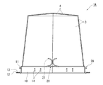
図1は、本考案に係るジョイントボックス1Aの第1の実施形態の構成を示す斜視図である。また、図2は図1に示すジョイントボックス1Aの正面図であり、図4は同じく平面図であり、図7は同じく底面図である。この他にも、図3は、図1に示すジョイントボックス1Aの留板12を係止した状態の正面図である。また、図5は図4のI−I線矢視縦断面図、図6は図4のII−II線矢視縦断面図である。
FIG. 1 is a perspective view showing a configuration of a first embodiment of a
第1の実施形態のジョイントボックス1Aは、先端相互が結束された複数の絶縁被覆電線61(例えば図8に示す)を束ねて処理される結線束6(図9に示す)に被せて絶縁保護する為のカバーである。ジョイントボックス1Aは、図1乃至図7に示すように、台座2Aと、周壁3と、端面部材4とを備えている。台座2Aは、さらに、図1及び図7などに示すように、枠板10と、第一弁体21及び第二弁体群20とを有する。
The
なお、ここでは、端面部材4が連結される周壁3の一方の端部を上端部とし、台座2Aが連結される周壁3の他方の端部を下端部とする上下方向の定義にて記載している。したがって、上下方向を逆に定義する場合には、以降の記載においても、その定義で読み替えることができる。例えば、結線束6の頭部が下側に向き、端面部材4を下方、台座2Aを上方として、ジョイントボックス1Aを結線束6の頭部に被せる場合などである。また、左右方向についても同様とする。
In addition, it describes with the definition of an up-down direction which makes one edge part of the surrounding
周壁3は、結線束6の頭部の周囲を囲むように位置させる。周壁3は、中空の収容空間が設けられた筒状とされる。周壁3(の筒状)は、ジョイントボックス1Aの長手方向に対する垂直断面が多角形の形状に形成される。図1の実施例では、多角形の形状は正六角形である。周壁3のその断面積は、図4乃至図6を参照してわかるように、下部から上部に向けて次第に小さくなる。
The
端面部材4は、結線束6の上部側に位置せると共に、周壁3の上端部を覆うように連結される。図1乃至図6に示す端面部材4は、上部に頂点を設けて周壁3の上端部までに傾斜をつけるように板材で囲むように形成されている。なお、端面部材4を平らな板材で形成してもよい。
The
台座2Aでは、枠板10が周壁3の下端部に連結される。台座2Aには、周壁3及び端面部材4で囲まれる収容空間に、結線束6の頭部を端面部材4の方向に向けて挿入可能な開口部(枠板10の内周側の開口)が設けられる。
In the pedestal 2 </ b> A, the
台座2Aの開口部は、図7に示すように、複数の第一弁体21及び第二弁体群20で覆われている。ジョイントボックス1Aの長手方向に対する台座2Aの断面形状は、図7に示すように、周壁3の断面形状に相似した形状である。
The opening of the
すなわち、枠体10の断面形状は、周壁3における多角形の形状に相似した形状で、枠体10の高さ(ジョイントボックス1Aの長手方向)は、周壁3の高さよりも十分低く形成された、板状の枠である。その枠の外形は、周壁3の下端部側の外形のサイズと同一またはそれよりも大きく形成される。
That is, the cross-sectional shape of the
枠体10の内周側には、複数の第一弁体21及び第二弁体群20が周設(接続)される。ここで、第二弁体群20は、図7に示すように、第二弁体25a、25b及び25cから構成される。詳しくは、後述するように、複数の第一弁体21及び第二弁体25a、25b、25cの隣り合う各々が、間隔を設けて台座2Aの中央部に向く状態で周設される。さらに、第一弁体21及び第二弁体群20は、台座2Aの開口部(枠体10の開口)を開口可能なように覆う。
A plurality of
第一弁体21は、板状が伸びきった状態において、枠体10の内周側の対向する一組の辺に各々を一辺、又は、各々を分割した辺を一辺とする略四角形の板状とされる。第二弁体25a、25b及び25cは、枠体10の上記一組の辺以外の他の辺の各々を底辺、又は、各々を分割した辺を底辺とする略三角形の板状とされる。
The
第一弁体21、第二弁体25a、25b及び25cは、結線束6を周壁3及び端面部材4で囲まれる収容空間に挿入する場合においては当該挿入を許容する弾力性を有し、かつ、結線束6に対してジョイントボックス1Aを被せ付けた後の場合においては当該ジョイントボックス1Aの自重によってジョイントボックス1Aが抜脱しない弾力性を有する。
The
第一弁体21は、図7に示すように、主に台座2Aの中央部付近の開口部を覆う。第一弁体21は、略四角形の片(薄い板厚の板状)からなり、略四角形の長手方向に沿って切込部22が設けられる。
As shown in FIG. 7, the
切込部22は、板状の先端部から切り込みまたは二股構造とされる。切り込みは、1つ、又は、複数あってもよい。また、二股構造とは、先端部からの幅を有する一部の切り抜きであり、その切り抜きが複数(三股以上も含む)あってもよい。第一弁体21において、この切込部22の構造により、板状の先端部からこの切込部22にかけての位置がより曲がり易くなる。
The
図7の例では、略四角形の長手方向に沿って板状の先端部の中央から板状の中央部付近にかけて、二股構造を有する切込部22が設けられている。第一弁体21は、この切込部22の構造により、板状の先端部から中央部付近にかけて曲がり易くなる。
In the example of FIG. 7, a
さらに、図1、図5乃至図7に示すように、第一弁体21の切込部22が設けられた先端部分において、丸みを帯びるように、又は、弧を描くように流線型に曲がっている構造を有する。これにより、挿入される結線束6の頭部にかかる抵抗を小さくすることができる。
Further, as shown in FIGS. 1 and 5 to 7, the front end portion of the
以上のような第一弁体21は、切込部22側の先端部分が台座2Aの中央部に向くように、枠体10の内周側の一辺に第一間隔23を設けて2つの片が周設され、また、対向側の他の一辺にも同様に2つの片が周設される。また、第一弁体21は、隣り合う第二弁体25aと第二間隔24を設けて、周設される。
The
結線束6(例えば電線束の数、束の大きさ等)に応じて、例えば小束には、切込部22が有効に作用する。また、大束には、切込部22、第一間隔23及び第二間隔24が有効に作用する。
Depending on the connection bundle 6 (for example, the number of wire bundles, the size of the bundle, etc.), for example, the
以上のような、第一弁体21の構造及び弾力性により、結線束6に損傷を与えることなく、かつ、第一弁体21自体にも損傷を受けにくい。
Due to the structure and elasticity of the
さらに、好ましくは、第一弁体21は、図1、図5及び図6に示すように、結線束6にジョイントボックス1Aを被せ付ける前の状態において、枠体10の内周側の一組の辺から延設された一の第一弁体21の先端部と対向する他の第一弁体21の先端部とが、互いに接触に至る直前又は軽く接触する程度で、かつ、互いに反対方向を向くように端面部材4側に流線型に曲がるような弾力性を有するように形成される。
Further, preferably, the
さらに、第一弁体21は、図8及び図9に示すように、結線束6に対してジョイントボックス1Aを被せ付けた後の状態において、第一弁体21が結線束6の嵩のある頭部の周囲の電線62やコネクタ63により押し曲げられた場合でも、結線束6における嵩のある頭部の下側の掛り合いする位置に向かうような弾力性を有するように形成される。
Further, as shown in FIGS. 8 and 9, the
第二弁体群20は、図7に示すように、主に台座2Aの中央部以外の開口部を覆う。そのために、第二弁体群20は、第一弁体21が周設される枠体10の辺以外の内周側の辺に、複数が周設される。それらの辺に周設される第二弁体群20は、略三角形の複数の片からなる。
As shown in FIG. 7, the second
具体的には、第二弁体群20は、図7に示すように、略三角形の3つの片(第二弁体25a、25b及び25c)からなる。各々の略三角形の片の一つの頂点の先端部分が、台座2Aの中央部に向けて、丸みを帯びた流線型に形成されている。第二弁体25a、25b及び25cの各々が、全体で弾力性を有する構造となっている。
Specifically, as shown in FIG. 7, the second
第二弁体25a、25b及び25cは、略三角形の片の板厚方向に貫通する中抜き構造を有する。具体的には、第二弁体25aは、中抜き構造26aを有する。また、第二弁体25bは中抜き構造26bを有し、第二弁体25cは中抜き構造26cを有する。
The
中抜き構造部26a、26b及び26cは、各々、略三角形の片の中央付近がさらに小形状の三角形でくり貫かれている。なお、中抜き構造部26a、26b及び26cの形状は、この他にも、丸、四角形などでもよい。このくり貫き形状の大きさは、結線束6のコネクタ63などが引っ掛からない程度に考慮される。このようなくり貫き形状により、第二弁体群20は、結線束6の挿入に対してより曲がり易くなる。
Each of the
第二弁体25a、25b及び25cは、第一弁体21が周設される枠体10の一組の辺以外の内周側の他の辺の各々から、互いに接触に至る前まで延設される。第二弁体25a、25b及び25cは、台座2Aの中央部に向く略三角形の板状の先端部が丸みを帯びるように、かつ、当該板状全体が弾力性を有するように形成される。
The
図7に示すように、第二弁体25aと第二弁体25bとの間には、第三間隔27が設けられる。また、第二弁体25bと第二弁体25cとの間には第四間隔28が設けられ、一辺の第二弁体25cとそれと隣り合う第二弁体25cとの間には第五間隔29が設けられる。
As shown in FIG. 7, a
第二弁体群20は、以上のような構成により、主に台座2Aの中央部以外の開口部を覆う。これにより、例えば図8に示すように、結線束6に対して当該ジョイントボックス1Aを被せ付けた後の状態において、第一弁体21が結線束6の嵩のある頭部の周囲の電線62により押し曲げられた場合でも、第二弁体群20は、結線束6の頭部からジョイントボックス1Aが抜け出すのを防止するように、結線束6における嵩のある頭部の下側の掛り合い可能な位置にある。
The 2nd
枠体10の外周側には、図2及び図3に示すように、複数の留板係止部11および当該留板係止部11に係合する折り畳み可能な複数の留板12が形成される。さらに、留板12には、留板係止部11の突起が貫通可能なように、留板孔13が設けられる。
As shown in FIGS. 2 and 3, a plurality of retaining
また、枠体10には、例えば結束バンド71(図11)を枠体10の板厚方向に貫通させて棒状の固定物(例えば図11に示す棒部7)に固定可能な結束バンド孔14が複数設けられる。
The
例えば、図2などに示すように、台座2Aの枠板10の2箇所の位置に、造営材固定用の取付脚として留板12が設けられる。また、枠板10の他の箇所に、鉄棒、吊ボルト等の棒部7へジョイントボックス1Aを固定可能にする結束バンド71を通すための4組(1組が2つの孔)の結束バンド孔14が設けられる。
For example, as shown in FIG. 2 etc., the
本実施形態のジョイントボックス1Aでは、周壁3の断面形状及び台座2Aの断面形状(及び底面)が正六角形の形状である例を示すものであるが、本発明に係る他の実施形態として、多角形の辺の比は問わない。例えば、同じ多角形の辺数とすると、台座2Aの開口部を覆う第一弁体21の割合を小さくしたい場合、第一弁体21が周設される辺を小さく設ける。一方、第一弁体21の割合を大きくしたい場合、第一弁体21が周設される辺を大きく設ける等である。すなわち、弁体構造と相まって、さらに周壁3、台座2A等の断面の形状(多角形数、辺の比の組み合わせ等)により第一弁体21が開口部を覆う割合を決定することができる。
In the
また、ジョイントボックス1Aの製作面での優位点として、第一弁体21の形状は略四角形状であるため、枠体10の内周側の一辺に後付する等の取り付けが構造的にも容易である。例えば、第一弁体21を除いた台座2Aと、周壁3と、端面部材4とを一体成型で製作し、後工程で、枠体10の内周側の一辺に2つの片で一組の第一弁体21を接続し、それと対向するもう一辺に2つの片で一組の第一弁体21を接続することが容易である。
Further, as an advantage in terms of manufacturing the
これにより、一体成型では、例えば材料に硬めの合成樹脂としてポリプロピレンを用い、後工程(後付)では、材料に柔らかめの合成樹脂としてポリエチレンなどを用いることにより、ジョイントボックス1Aの量産的製造が可能である。この場合には、第二弁体群20が硬めの材料となり、第一弁体21が柔らかめの材料となるため、第一弁体21の弾力性をより高めることができる。なお、本例示の材料は一例であり、これらの材料に限定されるものではない。
Thus, in the integral molding, for example, polypropylene is used as a hard synthetic resin for the material, and in the later process (retrofit), polyethylene or the like is used as a soft synthetic resin for the material, thereby allowing mass production of the
図8に、第1の実施形態のジョイントボックス1Aに結線束6を挿入した状態を示す。また、図9は、図8に示すジョイントボックス1Aの正面図である。
FIG. 8 shows a state where the
図8及び図9に示すように、結線束6は、例えば複数の絶縁被覆電線61がコネクタ63などにより電線62の先端相互が結束され、処理(電線62の先端側の折り曲げ、丸めなど)されたものである。第一弁体21及び第二弁体群20は、図8及び図9に示すように、ジョイントボックス1Aに挿入された結線束6の絶縁被覆電線61、電線62、コネクタ63などを軽度な力で押さえる。したがって、複数の絶縁被覆電線61を結線後に、結線束6に上からジョイントボックス1Aを被せることにより、台座2Aの第一弁体21及び第二弁体群20の押さえにより、ジョイントボックス1Aがこの接続ポイントより外れ難い。
As shown in FIGS. 8 and 9, the
図10は、ジョイントボックス1Aから結線束6を取り出す状態を示す正面図である。
FIG. 10 is a front view showing a state in which the
一方、電気配線工事の点検等によりジョイントボックス1Aを結線束6から取り外す場合、図10に示すように、ジョイントボックス1Aを引き上げると、この作業過程で、台座2Aの開口部側の中央付近に位置する第一弁体21が、台座2Aの下方側(この場合にはジョイントボックス1Aの取り外し方向と反対側とする)に向けて、第一弁体21の先端部の丸みが回転して舌状に伸びる。この第一弁体21による伸長作用により、結線束6の電線62、コネクタ63などを傷つけることなく、ジョイントボックス1Aをスムーズに取り外すことができる。
On the other hand, when the
また、従来のジョイントボックスの弁体の構造に比べて、第一弁体21の柔軟な構造によって、第一弁体21の根元と板枠10との接続部に過渡な力がかからず、第一弁体21が根元から破損したり、台座2Aから取れ易くなることを防ぐことができる。
Moreover, compared with the structure of the valve body of the conventional joint box, the transitional force is not applied to the connection part of the base of the
以上のような弁体の構造により、作業員は、ジョイントボックス1Aへの結線束6の挿入をよりスムーズに行うことができる。また、ジョイントボックス1Aの開口部の中央付近から容易に結線束6を取り出すことができるため、結線束6の取り出しの際にも電線62、コネクタ63等を傷めることない。また、弁体を破損するような無理な力を要しない。
With the structure of the valve body as described above, the worker can more smoothly insert the
電気配線工事の現場において、本実施形態のジョイントボックス1Aを用いることにより、複数の絶縁被覆電線61を束ねて処理する結線束6にすばやく、かつ、容易に取り付けることができるため、作業時間及び労力を軽減することができる。すなわち、作業効率を高めることができる。
By using the
また、本実施形態のジョイントボックス1Aは、第一弁体21が周設された台座2Aの中央部分から結線束6を挿入し易くし、かつ、それによる容易に開口可能な面積の割合を大きくとれるため、より多数の電線を収容できる。これにより、従来のジョイントボックスでは、二箇所に分けていた接続を一箇所に集中することができるため、作業効率を高めることができる。
Further, the
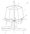
図11は、ジョイントボックス1Aを結束バンド71で固定した状態を示す斜視図である。
FIG. 11 is a perspective view showing a state in which the joint box 1 </ b> A is fixed by the binding
例えば、複数の絶縁被覆電線61を束ねて処理した結線束6にジョイントボックス1Aを被せた後に、図11に示すように、結束バンド71を結束バンド孔14に通して、鉄棒、吊ボルト等の棒部7にジョイントボックス1Aを固定することができる。
For example, after covering the
また、造営材固定用の取付脚として用いられる、使用しない2箇所の留板12は、折り畳んで留板係止部11に係止させておくことができる。
Further, the two retaining
以上のように、一つのジョイントボックス1Aでの固定方法に関して、一つの固定方法だけでなく、複数の選択が可能となる。これにより、固定場所が限定されず、造営材や、棒部などに固定することができる。このため、複数種類のジョイントボックスを用意する必要がないため、作業効率を高めることができる。
As described above, regarding the fixing method in one
第1の実施形態のジョイントボックスによれば、多くの電線を束ねて処理しても容易に被ることができ、また、容易に取り外すことができる。 According to the joint box of 1st Embodiment, even if it bundles and processes many electric wires, it can be easily covered and can also be removed easily.
また、第1の実施形態のジョイントボックスによれば、より多くの結線束を収容することができ、固定方法に関しても複数の選択が可能となるため、作業効率を高めることができる。 In addition, according to the joint box of the first embodiment, more connection bundles can be accommodated, and a plurality of selections can be made with respect to the fixing method, so that work efficiency can be improved.
[第2の実施形態]
図12は、本考案に係るジョイントボックス1Bの第2の実施形態の構成を示す斜視図である。
[Second Embodiment]
FIG. 12 is a perspective view showing the configuration of the second embodiment of the
第2の実施形態のジョイントボックス1Bは、第1の実施形態のジョイントボックス1Aと同様に、先端相互が結束された複数の絶縁被覆電線61(例えば図8に示す)を束ねて処理される結線束6(図9に示す)に被せて絶縁保護する為のカバーである。
In the
ジョイントボックス1Bは、図12に示すように、台座2Aと、周壁3Bと、端面部材4Bとを備えている。なお、図12に示す台座2Aは、前述した図1及び図7などに示す台座2Aと同様な構成であるため、ここではその説明は省くものとする。以下、第1の実施形態のジョイントボックス1Aの構成と異なる、周壁3B及び端面部材4Bについて主に説明する。
As shown in FIG. 12, the
図12に示す周壁3Bの断面形状は、正六角形である。また、ジョイントボックス1Bにおける周壁3Bの断面積は、ジョイントボックス1Bの長手方向のいずれの位置においても同じ面積である。
The cross-sectional shape of the
周壁3Bの下端部は、台座2Aに連結される。ジョイントボックス1Bの長手方向に対する台座2Aの断面形状は、周壁3Bの断面形状に相似した形状、すなわり、正六角形である。
The lower end of the
端面部材4Bは、正六角形状の平らな板材で形成され、周壁3Bの上端部に連結される。図12に示す周壁3B及び端面部材4Bの形状は、図1に示す周壁3及び端面部材4の形状よりも簡易な形状である。
The
また、台座2Aの断面積が同一である場合、図12に示すジョイントボックス1Bは、図1に示すジョイントボックス1Aに比べて、結線束6の収容空間の体積をより大きくとることができる。
Moreover, when the cross-sectional area of the
第2の実施形態のジョイントボックスによれば、多くの電線を束ねて処理しても容易に被ることができ、また、容易に取り外すことができる。 According to the joint box of the second embodiment, even if many electric wires are bundled and processed, they can be easily covered and can be easily removed.
また、第2の実施形態のジョイントボックスによれば、より多くの結線束を収容することができ、固定方法に関しても複数の選択が可能となるため、作業効率を高めることができる。 In addition, according to the joint box of the second embodiment, more connection bundles can be accommodated, and a plurality of selections can be made with respect to the fixing method, so that work efficiency can be improved.
[第3の実施形態]
図13は、本考案に係るジョイントボックス1Cの第3の実施形態の構成を示す斜視図である。また、図14は、図13に示すジョイントボックス1Cの底面図である。
[Third Embodiment]
FIG. 13: is a perspective view which shows the structure of 3rd Embodiment of the joint box 1C which concerns on this invention. FIG. 14 is a bottom view of the joint box 1C shown in FIG.
第3の実施形態のジョイントボックス1Cは、第1の実施形態のジョイントボックス1Aと同様に、先端相互が結束された複数の絶縁被覆電線61(例えば図8に示す)を束ねて処理される結線束6(図9に示す)に被せて絶縁保護する為のカバーである。
As with the
ジョイントボックス1Cは、図13に示すように、台座2Bと、周壁3Cと、端面部材4Cとを備えている。台座2Bは、さらに、図14に示すように、枠板10と、第一弁体21及び第二弁体群20とを有する。また、図13に示す枠板10には、第1の実施形態のジョイントボックス1Aと同様に、留板係止部11、留板12及び留板孔13、結束バンド孔14が設けられる。なお、これらの機能については、前述した第1の実施形態で説明した内容と同様であるため、ここではその説明を省く。
As shown in FIG. 13, the joint box 1C includes a
周壁3C(の筒状)は、ジョイントボックス1Cの長手方向に対する垂直断面が多角形として、正八角形の形状に形成される。多角形の形状は、図1の実施例では正六角形であったが、本実施例では正八角形とするものである。周壁3Cのその断面積は、下部から上部に向けて次第に小さくなる。
The
ここで、図7の台座2A(断面が正六角形)と図14の台座2B(断面が正八角形)との開口部全体の面積の比率に基づいて、第一弁体21と第二弁体群20とで開口部を覆う割合を比べるとする。そうすると、図14に示す台座2Bの開口部全体の面積に占める第一弁体21と第二弁体群20と、図7に示す台座2Aのその割合が異なることになる。
Here, the
具体的には、図7の台座2Aにおける第一弁体21が開口部を覆う割合が、図14の台座2Bにおける第一弁体21が開口部を覆う割合よりも大きい。このことは、図7の台座2Aを備えるジョイントボックス1Aが、図14の台座2Bを備えるジョイントボックス1Cに比べて、より大束の結線束6を挿入し易い構造であると言える。
Specifically, the ratio of the
すなわち、結線束6を、例えば電線62などを束ねる本数により小束、中束、大束のように区分した場合、第一弁体21が開口部を覆う割合により、小束及び中束に適した台座2Bの断面形状や辺数、中束及び大束に適した台座2Aなどのように前述した実施形態のジョイントボックス1A、1Bや、本実施形態のジョイントボックス1C等の用途を決定してもよい。
That is, when the
本実施形態のジョイントボックス1Cでは、周壁3Cの断面形状及び台座2Bの断面形状(及び底面)が正八角形の形状である例を示すものであるが、本発明に係る他の実施形態として、多角形の辺数、及び、多角形の辺の比は問わない。
In the joint box 1C of the present embodiment, an example in which the cross-sectional shape of the
例えば、同じ多角形の辺数とすると、台座2Bの開口部を覆う第一弁体21の割合を小さくしたい場合、第一弁体21が周設される辺を小さく設ける。一方、第一弁体21の割合を大きくしたい場合、第一弁体21が周設される辺を大きく設ける等である。すなわち、弁体構造と相まって、さらに周壁3C、台座2B等の断面の形状(多角形数、辺の比の組み合わせ等)により第一弁体21が開口部を覆う割合を決定することができる。
For example, assuming that the number of sides of the same polygon is the same, if it is desired to reduce the ratio of the
第3の実施形態のジョイントボックスによれば、多くの電線を束ねて処理しても容易に被ることができ、また、容易に取り外すことができる。 According to the joint box of the third embodiment, even if many electric wires are bundled and processed, they can be easily covered and can be easily removed.
また、第3の実施形態のジョイントボックスによれば、より多くの結線束を収容することができ、固定方法に関しても複数の選択が可能となるため、作業効率を高めることができる。 Moreover, according to the joint box of 3rd Embodiment, more connection bundles can be accommodated, Since a several selection is also possible regarding a fixing method, work efficiency can be improved.
[他の実施形態]
以上、本考案の実施形態を説明したが、これらの実施形態は、例として提示したものであり、考案の範囲を限定することは意図していない。また、例えば各実施形態の特徴を組み合わせてもよい。さらに、これらの実施形態は、その他の様々な形態で実施されることが可能であり、考案の要旨を逸脱しない範囲で、種々の省略、置き換え、変更を行うことができる。これら実施形態やその変形には、考案の範囲や要旨に含まれると同様に、実用新案登録請求の範囲に記載された発明とその均等の範囲に含まれるものである。
[Other Embodiments]
As mentioned above, although embodiment of this invention was described, these embodiment is shown as an example and is not intending limiting the range of invention. For example, the features of the embodiments may be combined. Furthermore, these embodiments can be implemented in various other forms, and various omissions, replacements, and changes can be made without departing from the spirit of the invention. These embodiments and modifications thereof are included in the invention described in the claims of the utility model registration and equivalents thereof as well as included in the scope and gist of the invention.
1A、1B、1C…ジョイントボックス、2A、2B…台座、3、3B、3C…周壁、4、4B、4C…端面部材、6…結線束、7…棒部、10…枠体、11…留板係止部、12…留板、13…留板孔、14…結束バンド孔、20…第二弁体群、21…第一弁体、22…切込部、23…第一間隔、24…第二間隔、25a、25b、25c…第二弁体、26a、26b、26c…中抜き構造、27…第三間隔、28…第四間隔、29…第五間隔、61…絶縁被覆電線、62…電線、63…コネクタ、71…結束バンド
DESCRIPTION OF
第1の実施形態のジョイントボックス1Aは、先端相互が結束された複数の絶縁被覆電線61(例えば図8に示す)を束ねて処理される結線束6(図9に示す)に被せて絶縁保護する為のカバーである。ジョイントボックス1Aは、図1乃至図7に示すように、台座2Aと、周壁3と、端面部材4とを備えている。台座2Aは、さらに、図1及び図7などに示すように、枠体10と、第一弁体21及び第二弁体群20とを有する。
The
台座2Aでは、枠体10が周壁3の下端部に連結される。台座2Aには、周壁3及び端面部材4で囲まれる収容空間に、結線束6の頭部を端面部材4の方向に向けて挿入可能な開口部(枠体10の内周側の開口)が設けられる。
In the base 2 </ b> A , the
中抜き構造26a、26b及び26cは、各々、略三角形の片の中央付近がさらに小形状の三角形でくり貫かれている。なお、中抜き構造26a、26b及び26cの形状は、この他にも、丸、四角形などでもよい。このくり貫き形状の大きさは、結線束6のコネクタ63などが引っ掛からない程度に考慮される。このようなくり貫き形状により、第二弁体群20は、結線束6の挿入に対してより曲がり易くなる。
In the
例えば、図2などに示すように、台座2Aの枠体10の2箇所の位置に、造営材固定用の取付脚として留板12が設けられる。また、枠体10の他の箇所に、鉄棒、吊ボルト等の棒部7へジョイントボックス1Aを固定可能にする結束バンド71を通すための4組(1組が2つの孔)の結束バンド孔14が設けられる。
For example, as shown in FIG. 2 and the like, the retaining
また、従来のジョイントボックスの弁体の構造に比べて、第一弁体21の柔軟な構造によって、第一弁体21の根元と枠体10との接続部に過渡な力がかからず、第一弁体21が根元から破損したり、台座2Aから取れ易くなることを防ぐことができる。
Moreover, compared with the structure of the valve body of the conventional joint box, the transitional force is not applied to the connection part of the base of the
ジョイントボックス1Cは、図13に示すように、台座2Bと、周壁3Cと、端面部材4Cとを備えている。台座2Bは、さらに、図14に示すように、枠体10と、第一弁体21及び第二弁体群20とを有する。また、図13に示す枠体10には、第1の実施形態のジョイントボックス1Aと同様に、留板係止部11、留板12及び留板孔13、結束バンド孔14が設けられる。なお、これらの機能については、前述した第1の実施形態で説明した内容と同様であるため、ここではその説明を省く。
As shown in FIG. 13, the joint box 1C includes a
Claims (6)
前記結線束の頭部の周囲を囲むように位置させる、当該ジョイントボックスの長手方向に対する垂直断面が多角形の形状に形成された周壁と、
前記結線束の頭部を覆うように位置させると共に前記周壁の一方の端部を覆うように連結された端面部材と、
前記周壁の他方の端部に連結されて、前記周壁及び前記端面部材で囲まれる収容空間に前記結線束の頭部を前記端面部材の方向に向けて挿入可能な開口部が設けられ、前記開口部を開口可能なように覆う第一弁体及び第二弁体と、前記周壁における前記多角形の形状に相似させ、かつ、前記周壁の他方の端部側の外形のサイズと同一またはそれよりも大きく形成されて前記第一弁体及び第二弁体が内周側に周設される枠体とを有する台座と、を備え、
前記第一弁体は、板状が伸びきった状態において、前記枠体の前記内周側に対向する一組の辺に各々を一辺又は各々を分割した辺を一辺とする略四角形の板状とされ、当該略四角形の板状の長手方向に沿ってその先端部から切り込み又は二股構造を有し、前記第二弁体は、前記一組の辺以外の前記内周側の他の辺の各々を底辺又は各々を分割した辺を底辺とする略三角形の板状とされ、当該略三角形の板状の前記台座の中央部に向く先端部が丸みを帯びるように形成され、複数の前記第一弁体及び第二弁体の隣り合う各々が、間隔を設けて前記台座の中央部に向く状態で周設されて、
前記第一弁体及び第二弁体は、前記結線束を前記周壁及び前記端面部材で囲まれる収容空間に挿入する場合においては当該挿入を許容し、さらに、前記結線束に対して当該ジョイントボックスを被せ付けた後の場合においては当該ジョイントボックスの自重によって当該ジョイントボックスが抜脱しない弾力性を有する
ことを特徴とするジョイントボックス。 It is a joint box for insulating protection by covering a bundle of wires to be processed by bundling a plurality of electric wires whose ends are bound together,
A peripheral wall that is positioned so as to surround the periphery of the head of the wire bundle, and a vertical cross section with respect to the longitudinal direction of the joint box is formed in a polygonal shape;
An end face member that is positioned so as to cover the head of the wire bundle and is connected so as to cover one end of the peripheral wall;
An opening that is coupled to the other end of the peripheral wall and is capable of inserting the head of the wire bundle in the direction of the end surface member is provided in a housing space surrounded by the peripheral wall and the end surface member. A first valve body and a second valve body covering the portion so as to be openable, and similar to the polygonal shape of the peripheral wall, and the same or larger than the size of the outer shape on the other end side of the peripheral wall And a pedestal having a frame body formed so that the first valve body and the second valve body are provided on the inner peripheral side,
The first valve body has a substantially rectangular plate shape in which one side is divided into a set of sides facing the inner peripheral side of the frame body or a side obtained by dividing each side in a state where the plate shape is fully extended. And has a notch or bifurcated structure along the substantially rectangular plate-like longitudinal direction, and the second valve body is formed on the other side of the inner peripheral side other than the set of sides. Each plate has a substantially triangular plate shape with each of the bases or a divided side as a base, and a tip portion facing the center of the substantially triangular plate-like pedestal is rounded. Each of the adjacent one valve body and the second valve body is circumferentially provided in a state facing the central portion of the pedestal with an interval,
The first valve body and the second valve body allow the insertion when the connection bundle is inserted into a housing space surrounded by the peripheral wall and the end face member, and further, the joint box with respect to the connection bundle. A joint box characterized by having elasticity that prevents the joint box from being pulled out by the weight of the joint box after the cover is attached.
ことを特徴とする請求項1に記載のジョイントボックス。 The first valve body is further extended from one side of the set on the inner peripheral side of the frame body in a state before the joint box is covered with the connection bundle. The tip of the first valve body and the tip of the other first valve body extended from the other side of the set face in opposite directions just before or slightly touching each other. The joint box according to claim 1, wherein the joint box has elasticity such that the end surface member bends in a streamline shape.
ことを特徴とする請求項1又は請求項2に記載のジョイントボックス。 The joint box according to claim 1, wherein the second valve body has a hollow structure penetrating in a plate thickness direction in the substantially triangular plate shape.
ことを特徴とする請求項1乃至請求項3のいずれか一項に記載のジョイントボックス。 The said polygon is a regular hexagon or a regular octagon. The joint box as described in any one of Claim 1 thru | or 3 characterized by the above-mentioned.
ことを特徴とする請求項1乃至請求項4のいずれか一項に記載のジョイントボックス。 The plurality of foldable retaining plates that engage with the plurality of retaining plate engaging portions and the retaining plate engaging portions are formed on the outer peripheral side of the frame body. The joint box according to any one of the above.
ことを特徴とする請求項1乃至請求項5のいずれか一項に記載のジョイントボックス。
6. The frame according to any one of claims 1 to 5, wherein the frame is provided with a plurality of binding band holes through which the binding band penetrates in the plate thickness direction of the frame and can be fixed to a rod-like fixed object. A joint box according to claim 1.
Related Child Applications (1)
| Application Number | Title | Priority Date | Filing Date |
|---|---|---|---|
| JP2014087789A Continuation JP5574517B1 (en) | 2014-04-22 | 2014-04-22 | Joint box |
Publications (1)
| Publication Number | Publication Date |
|---|---|
| JP3189404U true JP3189404U (en) | 2014-03-13 |
Family
ID=
Similar Documents
| Publication | Publication Date | Title |
|---|---|---|
| JP2006311785A (en) | Protector | |
| JP6149746B2 (en) | Wire harness with protector | |
| JP2011239619A (en) | Branch holding jig for wiring harness | |
| JP3189404U (en) | Joint box | |
| JP5574517B1 (en) | Joint box | |
| JP5714661B2 (en) | Insulation protective cover | |
| JP5796541B2 (en) | Wire harness fixture | |
| JP5465509B2 (en) | Indirect hot-wire construction clip | |
| JP6386255B2 (en) | Wire Harness | |
| JP3194639U (en) | Slit tube | |
| KR101266247B1 (en) | Array tool of cable | |
| JP2017135877A (en) | Tube for wiring harness sheath, and wiring harness | |
| JP5896416B2 (en) | Electrical junction box | |
| JP6717879B2 (en) | Protector | |
| JP7075266B2 (en) | Wire fixture | |
| JP2012157093A (en) | Electric wire having protective member and method for manufacturing the same | |
| JP2007181307A (en) | Cable bundling tool and cable bundling method | |
| JP5541597B2 (en) | Output cable fixing structure of terminal box for solar cell module | |
| JP6887695B2 (en) | Resin member | |
| KR200416736Y1 (en) | A corrugate tube assembly for wiring protection | |
| WO2017110428A1 (en) | Wire harness | |
| JP3189736U (en) | Joint box | |
| JP5602258B2 (en) | Bird damage prevention tool | |
| WO2015072325A1 (en) | Wire harness and cable-retaining component | |
| KR101190851B1 (en) | Rope fixing apparatus for fishery |