JP3168317U - Plug for plug - Google Patents
Plug for plug Download PDFInfo
- Publication number
- JP3168317U JP3168317U JP2011001642U JP2011001642U JP3168317U JP 3168317 U JP3168317 U JP 3168317U JP 2011001642 U JP2011001642 U JP 2011001642U JP 2011001642 U JP2011001642 U JP 2011001642U JP 3168317 U JP3168317 U JP 3168317U
- Authority
- JP
- Japan
- Prior art keywords
- packing
- plug
- head
- mounting portion
- fitted
- Prior art date
- Legal status (The legal status is an assumption and is not a legal conclusion. Google has not performed a legal analysis and makes no representation as to the accuracy of the status listed.)
- Expired - Fee Related
Links
- 238000012856 packing Methods 0.000 claims abstract description 86
- 230000007423 decrease Effects 0.000 claims abstract description 6
- 229910052751 metal Inorganic materials 0.000 claims description 8
- 239000002184 metal Substances 0.000 claims description 8
- CWYNVVGOOAEACU-UHFFFAOYSA-N Fe2+ Chemical compound [Fe+2] CWYNVVGOOAEACU-UHFFFAOYSA-N 0.000 claims description 7
- 230000002093 peripheral effect Effects 0.000 claims description 7
- RYGMFSIKBFXOCR-UHFFFAOYSA-N Copper Chemical compound [Cu] RYGMFSIKBFXOCR-UHFFFAOYSA-N 0.000 claims description 6
- 229910052782 aluminium Inorganic materials 0.000 claims description 6
- XAGFODPZIPBFFR-UHFFFAOYSA-N aluminium Chemical compound [Al] XAGFODPZIPBFFR-UHFFFAOYSA-N 0.000 claims description 6
- 229910052802 copper Inorganic materials 0.000 claims description 6
- 239000010949 copper Substances 0.000 claims description 6
- XLYOFNOQVPJJNP-UHFFFAOYSA-N water Substances O XLYOFNOQVPJJNP-UHFFFAOYSA-N 0.000 description 3
- 238000001816 cooling Methods 0.000 description 1
- 239000000498 cooling water Substances 0.000 description 1
- 238000005520 cutting process Methods 0.000 description 1
- 238000003780 insertion Methods 0.000 description 1
- 230000037431 insertion Effects 0.000 description 1
- 238000009434 installation Methods 0.000 description 1
- 238000004519 manufacturing process Methods 0.000 description 1
- 239000000463 material Substances 0.000 description 1
Images

Landscapes
- Gasket Seals (AREA)
Abstract
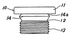
【課題】プラグ本体におけるパッキン取付部の製作が容易に行え、プラグ本体の頭部座面にパッキンを常時当接状態で移動不能にセットできるようにする。【解決手段】プラグ本体10とパッキン20を備えた詰栓用プラグ1におけるプラグ本体10の頭部11座面とくびれ部12との間にねじ部13の外径よりも大径でパッキン20の厚みとほぼ同幅のパッキン取付部14を設けると共に、パッキン取付部14の外周に頭部11座面に至るほど次第に縮径するテーパ凹部14aを形成する。パッキン20の内径をパッキン取付部14のテーパ凹部14aに嵌合可能な大きさとして、パッキン20をパッキン取付部14のテーパ凹部14aに嵌合保持するように構成した。【選択図】図1A packing mounting portion in a plug body can be easily manufactured, and the packing can be set so as to be immovable in a constantly contacted state with a head seating surface of the plug body. In a plug 1 having a plug body 10 and a packing 20, a plug 11 has a diameter larger than an outer diameter of a screw portion 13 between a seating surface of a head 11 of the plug body 10 and a constricted portion 12. A packing mounting portion 14 having a width substantially the same as the thickness is provided, and a tapered concave portion 14 a that gradually decreases in diameter toward the seat surface of the head 11 is formed on the outer periphery of the packing mounting portion 14. The packing 20 was configured to be fitted and held in the tapered recess 14a of the packing mounting portion 14 so that the inner diameter of the packing 20 could be fitted into the tapered recess 14a of the packing mounting portion 14. [Selection] Figure 1
Description
本考案は、主として自動車のエンジン内に溜まる水を水抜きするため、或いはオイル又は冷却水などを交換するためにオイルパンなどの収容体に設けられる詰栓用プラグに関するものである。 The present invention relates to a plug for plugs provided in a container such as an oil pan mainly for draining water accumulated in an engine of an automobile or exchanging oil or cooling water.
従来、たとえば、頭部を有し、頭部の下端にオイルパンなどの収容体における排出口のねじ孔に螺合可能なねじ部を設けたプラグ本体と、プラグ本体の頭部座面とねじ部との間に介装されるリング状のアルミ製又は銅製などの非鉄金属製パッキンとから構成される詰栓用プラグにおいて、頭部座面とねじ部との間に、ねじ部の外径よりも大径の筒状でかつその外周面にギザギザ溝や斜め方向の切り溝などの係合溝を有するパッキン取付部を設ける一方、パッキンの内径をパッキン取付部の係合部に嵌合可能な大きさとして、パッキンをパッキン取付部に軸方向に移動不能に取り付けるように構成したものが知られている。 2. Description of the Related Art Conventionally, for example, a plug body having a head and provided with a screw portion that can be screwed into a screw hole of a discharge port in a container such as an oil pan at the lower end of the head, and a head seating surface and a screw of the plug body In the plug for plugs composed of a ring-shaped aluminum or copper non-ferrous metal packing interposed between the head and the screw, the outer diameter of the screw is between the head seating surface and the screw. A packing attachment part with an engagement groove such as a jagged groove or a diagonal cut groove is provided on the outer peripheral surface of the cylinder, while the inner diameter of the packing can be fitted to the engagement part of the packing attachment part. As a large size, there is known a configuration in which the packing is attached to the packing mounting portion so as not to move in the axial direction.
これにより、プラグ本体の頭部座面に設けたパッキン取付部にパッキンを軸方向に対して移動不能にセットすることができるので、詰栓用プラグの収容体の排出口への螺合による着脱が簡単容易にでき、ロボットなどによる取り付けの自動化が容易に図り得るようにしている。 As a result, the packing can be set so as not to move in the axial direction on the packing mounting portion provided on the head seat surface of the plug body, so that the plug plug can be attached or detached by screwing it into the outlet of the container. This makes it easy to automate the installation by a robot or the like.
ところが、上記した詰栓用プラグによれば、プラグ本体の頭部座面に連設したパッキン取付部の外周面に、ギザギザ溝や斜め方向の切り溝などの係合溝を頭部座面の際まで設ける構造であるため、その係合溝の頭部座面際への溝加工が非常に複雑で高度な技術と手間を要する問題を有していた。また、詰栓用プラグをパッキン取付部に嵌合して取り付ける場合、詰栓用プラグを頭部座面に当接するまで、つまりパッキン取付部の外周面最奥部まで必ず確実に押し込む必要があった。 However, according to the plug for plugs described above, an engagement groove such as a jagged groove or a diagonal cut groove is formed on the outer peripheral surface of the packing mounting portion provided continuously with the head seat surface of the plug body. Since the structure is provided until the end, the groove processing of the engaging groove on the side of the head seating surface is very complicated and has a problem that requires advanced technology and labor. In addition, when the plug for plugging is fitted to the packing mounting part, it must be surely pushed in until the plug for plugging comes into contact with the head seat surface, that is, the innermost part of the outer peripheral surface of the packing mounting part. It was.
そこで本考案は、上記のような問題点を解消し、パッキン取付部の製作が容易に行えながら、プラグ本体の座面にパッキンを常時当接状態で移動不能にセットできるようにして、詰栓用プラグの収容体の排出口への螺合による着脱が簡単容易にでき、ロボットなどによる取り付けの自動化が容易に図り得る詰栓用プラグの提供を課題とする。 Therefore, the present invention eliminates the above-mentioned problems, makes it easy to manufacture the packing mounting part, and allows the packing to be set in a non-movable state in a constantly contacting state on the seat surface of the plug body. It is an object of the present invention to provide a plug for plugging that can be easily attached / detached by screwing a container for a container into a discharge port and that can be easily automated by a robot or the like.
上記した問題を解決するため、本願の請求項1記載の考案は、頭部を有し、頭部の下端にくびれ部を介して収容体における排出口のねじ孔に螺合可能なねじ部を設けてなるプラグ本体と、プラグ本体の頭部座面に介装されるリング状のパッキンとで構成される詰栓用プラグにおいて、プラグ本体の頭部座面とくびれ部との間にねじ部の外径よりも大径でパッキンの厚みとほぼ同幅のパッキン取付部を設けると共に、パッキン取付部の外周に頭部座面に至るほど次第に縮径するテーパ凹部を形成する一方、パッキンの内径をパッキン取付部のテーパ凹部に嵌合可能な大きさとして、パッキンをパッキン取付部のテーパ凹部に嵌合保持するように構成したことを特徴とする。 In order to solve the above-described problem, the device according to
また、本願の請求項2記載の考案は、請求項1記載のパッキンが、アルミ製又は銅製などの非鉄金属パッキンからなりリング状を呈する一方、その内周面の厚み方向中間部に該パッキンの厚みよりも薄肉で半径方向内方に突出する薄肉突出片を所定間隔置いて複数個備えていることを特徴とする。 Further, in the invention according to claim 2 of the present application, the packing according to
上記した詰栓用プラグによれば、テーパ凹部を有するパッキン取付部の形成が単純な切削加工により簡単容易に行うことができ、しかも、パッキンをパッキン取付部のテーパ凹部に嵌合したとき、テーパ凹部の座面に至るほど次第に縮径するテーパ面によりパッキンを積極的に頭部座面側に移動させるように作用させて保持することになるので、プラグ本体の座面にパッキンを常に当接状態にセットすることができる。その結果、詰栓用プラグの収容体の排出口への螺合による着脱が簡単容易にでき、ロボットなどによる取り付けの自動化が容易に図ることができる。 According to the plug for plug described above, the packing mounting portion having the tapered recess can be easily formed by a simple cutting process, and when the packing is fitted into the taper recess of the packing mounting portion, the taper mounting portion is tapered. Since the packing is positively moved to the head seat surface side by the taper surface that gradually decreases in diameter toward the seat surface of the recess, the packing is always in contact with the seat surface of the plug body. Can be set to state. As a result, the plugging plug can be easily attached and detached by screwing it into the outlet of the container, and the attachment by a robot or the like can be easily automated.
また、パッキンがアルミ製又は銅製などの非鉄金属製パッキンでリング状を呈する一方、その内周面の厚み方向中間部に該パッキンの厚みよりも薄肉で半径方向内方に突出する薄肉突出片を所定間隔置いて複数個備えている構成とすれば、非鉄金属製パッキンをパッキン取付部のテーパ凹部に嵌合する際、該パッキンの内周面に設けた複数個の薄肉突出片を容易に変形させて嵌合させることができるのでこのましい。 Also, while the packing is made of a nonferrous metal packing such as aluminum or copper, a thin protruding piece that is thinner than the thickness of the packing and protrudes inward in the radial direction is provided in the middle in the thickness direction of the inner peripheral surface. When a plurality of non-ferrous metal packings are provided at predetermined intervals, a plurality of thin protruding pieces provided on the inner peripheral surface of the packing can be easily deformed when the non-ferrous metal packing is fitted into the tapered recess of the packing mounting part. This is good because it can be fitted.
以下本考案の実施の形態を図に基づいて説明する。 Embodiments of the present invention will be described below with reference to the drawings.
図1及び図2において、1は水抜きをするためオイルパンなどの収容体(図示せず)の底部に設けられるドレン用としての詰栓用プラグを示すもので、この詰栓用プラグ1は、頭部11を有し、頭部11の下端にくびれ部12を介して収容体における排出口のねじ孔に螺合可能なねじ部13を設けてなるプラグ本体10と、プラグ本体10の頭部11座面に介装されるリング状のパッキン20とで構成される。上記頭部11の上面中央部には、締付用治具(図示せず)の挿入用角穴11aが形成されている。 1 and 2,
そして、頭部11座面とくびれ部12との間にねじ部13の外径よりもやや大径でパッキン20の厚みとほぼ同幅のパッキン取付部14を設けると共に、パッキン取付部14の外周に頭部11座面に至るほど次第に縮径するテーパ凹部14aを形成する一方、パッキン20の内径をパッキン取付部14のテーパ凹部14aに嵌合可能な大きさとして、パッキン20をパッキン取付部14のテーパ凹部14aに嵌合保持するように構成している。 A
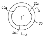
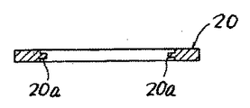
パッキン20は、アルミ製又は銅製などの非鉄金属パッキンからなり、図3及び図4に示すようにリング状を呈する一方、パッキン20の内周面にはその厚み方向中間部にパッキン20の厚みよりも薄肉で半径方向内方に突出する薄肉突出片20a…20aを所定間隔置いて複数個(図では三個)備えている。 The
また、図1に示すように、プラグ本体10のパッキン取付部14にパッキン20を嵌合してセットする場合、たとえばパッキン20をパッキン取付部14に圧入するプレス式の適宜圧入機(図示せず)などを用いて行う。 Further, as shown in FIG. 1, when the
次に、上記した詰栓用プラグの作用について説明する。 Next, the operation of the plug for plug described above will be described.
まず、プラグ本体10のパッキン取付部14にパッキン20を嵌合する場合、適宜圧入機(図示せず)を用いてパッキン20をプラグ本体10のねじ部からパッキン取付部14に圧入して嵌合する。その場合、パッキン20内周の薄肉突出片20a…20aを変形させながらパッキン取付部14のテーパ凹部14a内に入り込むように圧入する。そして、パッキン20をパッキン取付部14のテーパ凹部14aに嵌合したとき、テーパ凹部14aの座面に至るほど次第に縮径するテーパ面によりパッキン20を積極的に頭部11座面側に移動させるように作用させて保持することになる。これにより、パッキン20はくびれ部12側に位置ずれしたりすることなくプラグ本体10の頭部11座面にパッキン20を常に当接状態にセットできる。その結果、詰栓用プラグ1の収容体の排出口への螺合による着脱が簡単容易にでき、ロボットなどによる取り付けの自動化が容易に図ることができる。 First, when the
なお、上記した実施の形態では、オイルパンに設けられるドレン用としての詰栓用プラグ1について説明したけれども、何らドレン用のプラグ1に限定されるものではなく、たとえばオイル交換用のプラグや冷却水交換用のプラグなどいろいろな用途の詰栓用プラグに広く使用できることは勿論である。また、パッキン20としては、アルミ製又は銅製などの非鉄金属パッキン以外の材料からなるパッキンを用いることも可能である。 In the above-described embodiment, the plug for
1 詰栓用プラグ
10 プラグ本体
12 中心軸部
11 頭部
12 くびれ部
13 ねじ部
14 パッキン取付部
14a テーパ凹部
15a テーパ先端部
20 パッキン
20a 薄肉突出片DESCRIPTION OF
Claims (2)
Priority Applications (1)
| Application Number | Priority Date | Filing Date | Title |
|---|---|---|---|
| JP2011001642U JP3168317U (en) | 2011-03-08 | 2011-03-08 | Plug for plug |
Applications Claiming Priority (1)
| Application Number | Priority Date | Filing Date | Title |
|---|---|---|---|
| JP2011001642U JP3168317U (en) | 2011-03-08 | 2011-03-08 | Plug for plug |
Publications (1)
| Publication Number | Publication Date |
|---|---|
| JP3168317U true JP3168317U (en) | 2011-06-09 |
Family
ID=54879306
Family Applications (1)
| Application Number | Title | Priority Date | Filing Date |
|---|---|---|---|
| JP2011001642U Expired - Fee Related JP3168317U (en) | 2011-03-08 | 2011-03-08 | Plug for plug |
Country Status (1)
| Country | Link |
|---|---|
| JP (1) | JP3168317U (en) |
-
2011
- 2011-03-08 JP JP2011001642U patent/JP3168317U/en not_active Expired - Fee Related
Similar Documents
| Publication | Publication Date | Title |
|---|---|---|
| JP3168317U (en) | Plug for plug | |
| JP2017522510A (en) | Pressure seal with elastomeric body | |
| CN204262395U (en) | A kind of tile type fixture for thin-wall workpiece | |
| CN202667527U (en) | Cold heading forming mold | |
| CN205136312U (en) | Vehicle vent -pipe bolt | |
| CN203289232U (en) | Insert structure | |
| JP3168318U (en) | Plug for plug | |
| CN204412945U (en) | The resetting chuck of high accuracy punch die | |
| CN211819558U (en) | A plug-in hybrid vehicle oil pan liquid release plug | |
| CN103722528B (en) | Stifle expansion device and dilate method | |
| CN204075309U (en) | A kind of drill jig for holing to reel | |
| JP2014210323A (en) | Collet chuck | |
| CN204201025U (en) | A kind of ransaxle adjusting nut | |
| CN204253640U (en) | A kind of bearing unit with profile of tooth seat | |
| CN204985371U (en) | Multi -wire saw's transmission shaft bearing closing device | |
| JP5794841B2 (en) | Fastening structure | |
| CN204477046U (en) | A kind of connecting rod cast blank with tank structure | |
| CN202894849U (en) | Flat turbine head end face clamp structure | |
| JP3228548U (en) | Closing plug | |
| CN204186725U (en) | A kind of easy-to-dismount locating stud | |
| CN202418610U (en) | Direct stroke cut-off valve | |
| JP3176402U (en) | Retaining washer for bolt | |
| CN210876803U (en) | Large inlaid ring gear extrusion die | |
| CN205977984U (en) | Integration nut | |
| JP6009979B2 (en) | Oil seal removal jig |
Legal Events
| Date | Code | Title | Description |
|---|---|---|---|
| R150 | Certificate of patent or registration of utility model |
Ref document number: 3168317 Country of ref document: JP Free format text: JAPANESE INTERMEDIATE CODE: R150 Free format text: JAPANESE INTERMEDIATE CODE: R150 |
|
| FPAY | Renewal fee payment (event date is renewal date of database) |
Free format text: PAYMENT UNTIL: 20140518 Year of fee payment: 3 |
|
| R250 | Receipt of annual fees |
Free format text: JAPANESE INTERMEDIATE CODE: R250 |
|
| R250 | Receipt of annual fees |
Free format text: JAPANESE INTERMEDIATE CODE: R250 |
|
| R250 | Receipt of annual fees |
Free format text: JAPANESE INTERMEDIATE CODE: R250 |
|
| R250 | Receipt of annual fees |
Free format text: JAPANESE INTERMEDIATE CODE: R250 |
|
| R250 | Receipt of annual fees |
Free format text: JAPANESE INTERMEDIATE CODE: R250 |
|
| LAPS | Cancellation because of no payment of annual fees |