JP3152201U - Planter water supply equipment - Google Patents
Planter water supply equipment Download PDFInfo
- Publication number
- JP3152201U JP3152201U JP2009003014U JP2009003014U JP3152201U JP 3152201 U JP3152201 U JP 3152201U JP 2009003014 U JP2009003014 U JP 2009003014U JP 2009003014 U JP2009003014 U JP 2009003014U JP 3152201 U JP3152201 U JP 3152201U
- Authority
- JP
- Japan
- Prior art keywords
- water
- float
- planter
- chamber
- water supply
- Prior art date
- Legal status (The legal status is an assumption and is not a legal conclusion. Google has not performed a legal analysis and makes no representation as to the accuracy of the status listed.)
- Expired - Fee Related
Links
Images


Abstract
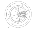
【課題】プランターの水供給装置として実用上好適な装置を提供する。【解決手段】下部に多孔板3を敷設して上部側を培土室5、下部側を貯水室4としたプランター1に、無底円筒体9を収容して前記貯水室4に通じる、フロート10の案内室を設ける。該案内室に円柱状のフロート10を縦動自在に嵌合し、該フロート10の上面中央に、フロート10が前記多孔板3位置に浮上したとき、一端の接触子が接する揺動片13の他端を、前記フロート案内室11の上壁に吊設した支承片に揺動自在に枢着する。そして、該揺動片13の長手方向の中間部には、前記上壁に設けた注水口を開閉する弁体を装置し、前記注水口にストレーナ15を介して連通する水道管路17を、前記プランター1外部に導出する。【選択図】図1An apparatus suitable for practical use as a water supply apparatus for a planter is provided. A float 10 in which a bottom plate is accommodated in a planter 1 in which a perforated plate 3 is laid in the lower part and the upper side is a culture chamber 5 and the lower side is a water storage chamber 4 and is connected to the water storage chamber 4 is provided. An information room will be provided. A columnar float 10 is vertically fitted in the guide chamber, and when the float 10 floats to the position of the perforated plate 3 at the center of the top surface of the float 10, The other end is pivotally attached to a support piece suspended from the upper wall of the float guide chamber 11. And in the middle part of the longitudinal direction of the rocking piece 13, a valve body for opening and closing a water inlet provided on the upper wall is installed, and a water pipe 17 communicating with the water inlet via a strainer 15 is provided. Derived outside the planter 1. [Selection] Figure 1
Description
本考案は、栽培植物が育成中の培土に自動的に水を供給するようにした、プランターの水供給装置に関するものである。 The present invention relates to a water supply device for a planter that automatically supplies water to a cultivated soil by a cultivated plant.
プランターの一側に給水装置を設け、給水装置は、上部側の貯水タンクからの水を、下部側の水溜室を経て培土室の培土中に給水するようにし、水溜室に装置したフロートが水溜室に溜め込まれた水量によって浮上して貯水タンクと水溜室間の止水弁を閉じて貯水タンクからの給水を中断し、水がなくなれば、止水弁が開放され水溜室への給水が行われ、培土中への水の供給を行うようにした構造のものがある(例えば、特許文献1)。 A water supply device is provided on one side of the planter, and the water supply device supplies water from the upper water storage tank to the soil in the soil storage chamber through the water storage chamber on the lower side, and the float installed in the water storage chamber is filled with water. The water floats up by the amount of water stored in the chamber, closes the water stop valve between the water storage tank and the water storage chamber, interrupts water supply from the water storage tank, and when the water runs out, the water stop valve is opened and water is supplied to the water storage chamber. There is a structure in which water is supplied to the soil (for example, Patent Document 1).
前記従来構造のものは、水溜室と培土室はその隔壁に設けた通水孔で連通しているので、水溜室と培土室は水位が同じとなり、水の供給過多となり、水供給装置として必ずしも適切ではない。 In the conventional structure, since the water storage chamber and the culture chamber are communicated with each other through a water passage hole provided in the partition wall, the water level of the water storage chamber and the culture chamber are the same, and the water supply is excessive. Not appropriate.
また、貯水タンクから得て水を供給するため、自動的に水を供給することを意図したにも係らず、貯水タンクへの水の供給を怠り、給水が中断されるおそれもあり、実用性に欠ける。 In addition, because water is obtained from the water storage tank and supplied automatically, there is a possibility that the water supply to the water storage tank may be neglected and water supply may be interrupted even though it is intended to supply water automatically. Lack.
本考案は、斯様な従来例の欠点に着目し、プランターの水供給装置として実用上好適な装置を提供することを目的として突出したものである。 The present invention focuses on the drawbacks of such a conventional example and protrudes for the purpose of providing a practically suitable device as a water supply device for a planter.
下部に多孔板を敷設して上部側を培土室、下部側を貯水室としたプランターに、無底円筒体を収容して前記貯水室に通じる、フロートの案内室を設け、該案内室に円柱状のフロートを縦動自在に嵌合し、該フロートの上面中央に、フロートが前記多孔板位置に浮上したとき、一端の接触子が接する揺動片の他端を、前記フロート案内室の上壁に吊設した支承片に揺動自在に枢着し、該揺動片の長手方向の中間部には、前記上壁に設けた注水口を開閉する弁体を装置し、前記注水口にストレーナを介して連通する水道管路を、前記プランター外部に導出したことを基本的手段とする。 A floater is installed in the planter with a perforated plate in the lower part and the upper part is a soil storage room and the lower part is a water storage room, and a bottomless cylindrical body is accommodated and communicates with the water storage room. A columnar float is fitted in a vertically movable manner, and the other end of the swinging piece with which the contact at one end contacts the upper surface of the float guide chamber when the float floats to the position of the perforated plate at the center of the upper surface of the float. A swinging pivot is pivotally attached to a support piece suspended from a wall, and a valve body for opening and closing a water inlet provided in the upper wall is provided at an intermediate portion in the longitudinal direction of the rocking piece. A basic means is that a water pipe communicating with a strainer is led out of the planter.
この基本的手段に無底円筒体で、フロートの案内室を取り囲んだ点を付加することにより成育する根がからまることなく、当初の状態を維持して水の供給操作を円滑に行うことができる。 By adding a point surrounding the float guide chamber to this basic means with a bottomless cylindrical body, it is possible to smoothly perform the water supply operation while maintaining the original state without entanglement of the root to grow. .
本考案によれば、培土室の下側に貯水室を配し、該貯水室に連通する案内室内においてフロートを浮上させて貯水室内への水の供給を自動的に中断させる構成を採るものであるから、水面が培土室の培土に接する位置以上に上昇することはなく、従って、培土への水の供給過多が生じることなく、実用的なプランターの水供給装置を提供でき、水道管路を利用するものであることから水の供給忘れが全くない、水の供給装置を提供できる。 According to the present invention, a water storage chamber is arranged below the soil storage chamber, and the float is floated in the guide chamber communicating with the water storage chamber to automatically interrupt the supply of water to the water storage chamber. Therefore, the water level does not rise above the position where it contacts the soil in the soil cultivating room, and therefore, a water supply device for a practical planter can be provided without excessive supply of water to the soil. Since it is used, it is possible to provide a water supply device that never forgets to supply water.
図面は本考案に係るプランターの水供給装置の一実施例を示し、1はプランターで、プランター1は、下部に収納した支持枠2上に多孔板3を載置、敷設して、内部を下部側の貯水室4と上部側の培土室5に区画し、培土室5に充填した培土e中に植物bを植込み、該植物bに前記貯水室4から培土eを通じて水を供給するようにしたものである。
The drawings show an embodiment of a water supply device for a planter according to the present invention, wherein 1 is a planter, and the planter 1 has a
図示、6は、プランター1を上部側の培土室5と下(底)部側の貯水室4とに区画する前記多孔板3に設けた嵌合孔7に嵌通させて、プランター1の底壁1a上に載置して立設した区画筒で、区画筒6で取り囲んで成る空室8は、該区画筒6を前記底壁1aとの間の隙間aを通じて前記貯水室4に連通し、この空室8には、区画筒6と同様に底壁1a上に無底円筒体9を載置して、該無底円筒体9で取り囲んで構成した、フロート10の案内室11を設けてある。
In FIG. 6, a planter 1 is inserted into a fitting hole 7 provided in the
案内室11は、該案内室11を構成する無底円筒体9と前記底壁1a間の隙間a´を通じて、前記空室8および前記隙間a順次介して前記貯水室4に連通し、空室8を通じて貯水室4に連通することにより、貯水室4と同水位になるようにしてある。
The guide chamber 11 communicates with the water storage chamber 4 through the gap 8 and the gap a sequentially through a gap a ′ between the bottomless
この案内室11には、該案内室11より径を小さくした円柱状の前記フロート10を縦動自在に嵌合し、該フロート10の上面中央には針部12bをフロート10内に嵌入させて一体的にした、金属製の補強片12を装置し、該補強片12によって一端の接触子13aが押し上げられる揺動片13を、前記無底円筒体9の上蓋材9bに揺動自在に支持させてある。
A
無底円筒体9は円筒主体9aの上端部に厚肉の前記上蓋材9bを嵌合、止着して構成し、上蓋材9bには、軸線上に注水口14aを備えた注水材14を螺合して取付け、注水材14の内側には、前記軸線上位置にして焼結金属で成るろ材15aを通じて前記注水口14aに連通するストレーナ15を設け、該ストレーナ15は、前記注水材14に螺合接続したホース接続材16に組付けたホース17に連通させてある。
The bottomless
一端に前記接触子13aを備えた前記揺動片13は、案内室11の上壁を構成する前記上蓋材9bに吊設した支承片18に他端を揺動自在に枢着され、この枢着部と前記接触子13aとの間すなわち長手方向の中間部に弁体19を装置し、該弁体19が接離する弁座20を前記注水口14aを構成する突子を前記注水材14に設けてある。
The
前記区画筒6は、上端部をプランター1内に収容した培土eより突出させて開口上端を蓋体6aで閉塞して、内側延いては貯水室4等への虫の侵入を防ぎ、植物bの根が無底円筒体9等にからまるのを防ぎ、円滑な水の供給操作を行うためのものである。前記ホース(供給管)17はこの区画筒6の蓋体6aを通じてプランター1外部に導出し元栓に連通して水道管路を構成する。
The
そして、水道管路すなわちホース17を通じて水を供給すると、水はストレーナ15でろ過されて注水口14aを通じて案内室11に注入され、案内室11と貯水室4は隙間a,a´を通じて連通しているので、同水位となって予め設定した多孔板3位置の水位まで上昇し、当該水位に至ると、案内室11内で浮上したフロートは接触子13aを押し上げ、その結果、揺動片13は揺動し、揺動片13に備えた弁体19は弁座20部に接触して注水口14aを閉塞して水の供給を中断させるのである。
When water is supplied through the water pipe, that is, the
そして、この状態で貯水室4中の水が培土eに浸み込んで植物bに吸引されて減少すると、フロート10は、該減少に従って降下し、降下によって弁体19が弁座20から離れ、再び注水口14aから水が供給され、植物bは適度に水が補給され、育成されるのである。
In this state, when the water in the water storage chamber 4 is soaked in the soil e and sucked and reduced by the plant b, the
1 プランター
3 多孔板
4 貯水室
9 無底円筒体
10 フロート
11 案内室
13 揺動片
13a 接触子
14a 注水口
15 ストレーナ
17 水道管路
18 支承片
DESCRIPTION OF SYMBOLS 1
Claims (2)
Priority Applications (1)
| Application Number | Priority Date | Filing Date | Title |
|---|---|---|---|
| JP2009003014U JP3152201U (en) | 2009-05-11 | 2009-05-11 | Planter water supply equipment |
Applications Claiming Priority (1)
| Application Number | Priority Date | Filing Date | Title |
|---|---|---|---|
| JP2009003014U JP3152201U (en) | 2009-05-11 | 2009-05-11 | Planter water supply equipment |
Publications (1)
| Publication Number | Publication Date |
|---|---|
| JP3152201U true JP3152201U (en) | 2009-07-23 |
Family
ID=54856535
Family Applications (1)
| Application Number | Title | Priority Date | Filing Date |
|---|---|---|---|
| JP2009003014U Expired - Fee Related JP3152201U (en) | 2009-05-11 | 2009-05-11 | Planter water supply equipment |
Country Status (1)
| Country | Link |
|---|---|
| JP (1) | JP3152201U (en) |
Cited By (1)
| Publication number | Priority date | Publication date | Assignee | Title |
|---|---|---|---|---|
| JP2013531493A (en) * | 2010-06-10 | 2013-08-08 | マン ソン,ヨン | Non-powered irrigation and nutrient solution apparatus and non-powered pot cultivation system using the same |
-
2009
- 2009-05-11 JP JP2009003014U patent/JP3152201U/en not_active Expired - Fee Related
Cited By (1)
| Publication number | Priority date | Publication date | Assignee | Title |
|---|---|---|---|---|
| JP2013531493A (en) * | 2010-06-10 | 2013-08-08 | マン ソン,ヨン | Non-powered irrigation and nutrient solution apparatus and non-powered pot cultivation system using the same |
Similar Documents
| Publication | Publication Date | Title |
|---|---|---|
| US6363658B1 (en) | Flower pot | |
| US5502924A (en) | Planter assembly having automatic water-feeding and drying intervals | |
| US20040035466A1 (en) | Float valve | |
| JP2021531830A (en) | Suspended flowerpot capable of automatic water supply | |
| JP2005525806A5 (en) | ||
| KR101774647B1 (en) | Water reservoir for pot | |
| JP3152201U (en) | Planter water supply equipment | |
| KR100835312B1 (en) | Humidifier and supplement water bucket for the same | |
| JP3985238B2 (en) | Action storage type siphon unit | |
| US8533995B1 (en) | Automatic watering device for plants | |
| JP3158180U (en) | Automatic water supply device | |
| US5743290A (en) | Multi-purpose automatic filling and leveling liquid basin with liquid transfer | |
| TWI355889B (en) | ||
| JPH11192031A (en) | Flowerpot with automatic water supply | |
| JP3765025B2 (en) | Automatic irrigation equipment | |
| EP2805090B1 (en) | Valve assembly | |
| JP4896189B2 (en) | Hydroponics equipment | |
| WO2007141704B1 (en) | A dispenser for dispensing a dosing liquid into a toilet cistern | |
| JPS585742Y2 (en) | Simple gray water system | |
| KR200417195Y1 (en) | Apparatus for Growing Sprouts | |
| RU2742148C1 (en) | Installation for automatic plant irrigation | |
| JP4977306B2 (en) | Automatic water supply device and automatic water supply system for plant cultivation containers | |
| RU2275796C1 (en) | Automatic waterer | |
| CN106912435A (en) | Magnetcisuspension valve hydrocone type aquarium automatic water changer | |
| AU782914B2 (en) | Flower pot |
Legal Events
| Date | Code | Title | Description |
|---|---|---|---|
| R150 | Certificate of patent (=grant) or registration of utility model |
Free format text: JAPANESE INTERMEDIATE CODE: R150 |
|
| FPAY | Renewal fee payment (prs date is renewal date of database) |
Free format text: PAYMENT UNTIL: 20120701 Year of fee payment: 3 |
|
| FPAY | Renewal fee payment (prs date is renewal date of database) |
Free format text: PAYMENT UNTIL: 20120701 Year of fee payment: 3 |
|
| FPAY | Renewal fee payment (prs date is renewal date of database) |
Free format text: PAYMENT UNTIL: 20130701 Year of fee payment: 4 |
|
| LAPS | Cancellation because of no payment of annual fees |