JP3148769U - Speed increase drive mechanism, bicycle with speed increase drive mechanism, wheelchair with speed increase drive mechanism - Google Patents
Speed increase drive mechanism, bicycle with speed increase drive mechanism, wheelchair with speed increase drive mechanism Download PDFInfo
- Publication number
- JP3148769U JP3148769U JP2008008815U JP2008008815U JP3148769U JP 3148769 U JP3148769 U JP 3148769U JP 2008008815 U JP2008008815 U JP 2008008815U JP 2008008815 U JP2008008815 U JP 2008008815U JP 3148769 U JP3148769 U JP 3148769U
- Authority
- JP
- Japan
- Prior art keywords
- axle
- chain
- drive mechanism
- pedal
- crank
- Prior art date
- Legal status (The legal status is an assumption and is not a legal conclusion. Google has not performed a legal analysis and makes no representation as to the accuracy of the status listed.)
- Expired - Fee Related
Links
- 230000007246 mechanism Effects 0.000 title claims abstract description 43
- 230000000149 penetrating effect Effects 0.000 claims abstract description 6
- 230000005540 biological transmission Effects 0.000 description 2
- 230000005484 gravity Effects 0.000 description 2
- 238000004519 manufacturing process Methods 0.000 description 2
- 230000035515 penetration Effects 0.000 description 2
- 230000002093 peripheral effect Effects 0.000 description 2
- 238000005452 bending Methods 0.000 description 1
- 229910003460 diamond Inorganic materials 0.000 description 1
- 239000010432 diamond Substances 0.000 description 1
- 230000000694 effects Effects 0.000 description 1
- 238000003672 processing method Methods 0.000 description 1
Images


Landscapes
- Automatic Cycles, And Cycles In General (AREA)
Abstract
【課題】安定性と安全性の高い車輪の増速機構を提供すること【解決手段】車軸貫通用のホールを備えた内側ケースと、内側ケース内面の端部に取り付けられたチェーンガイドと、ペダル付きクランクと、このペダル付きクランクの回転軸が貫通する外側ケースと、内側ケースのホールを貫通する車軸の先端に取り付けられ内側ケースと外側ケースにより形成されるケース内に位置する車軸歯車と、この車軸歯車とチェーンガイドとにかけられるチェーンと、ペダル付きクランクと一体化されておりケース内部でチェーンと噛み合う内歯の大型歯車とを有し、車軸の回転中心と大型歯の回転中心とペダル付きクランクの回転軸の回転中心が一致する増速駆動機構。【選択図】図6A speed increasing mechanism for a wheel having high stability and safety is provided. An inner case having a hole for penetrating an axle, a chain guide attached to an end of the inner surface of the inner case, and a pedal. A crank with a shaft, an outer case through which a rotating shaft of the crank with a pedal passes, an axle gear mounted in a tip of an axle passing through a hole in the inner case and formed in a case formed by the inner case and the outer case, A chain that is hung on an axle gear and a chain guide, and a large gear with an internal tooth that is integrated with a crank with a pedal and meshes with the chain inside the case. A speed increasing drive mechanism in which the rotation centers of the rotating shafts coincide. [Selection] Figure 6
Description
本考案は自転車の車輪、特に前輪駆動方式の自転車の前輪、車椅子の車輪等、車輪軸をクランクやペダル等で駆動する場合における増速のための増速駆動機構、及び、前輪に増速駆動機構を用いた自転車の簡素化されたフレーム構造に関する。 The present invention is a bicycle wheel, in particular, a front wheel drive type bicycle front wheel, a wheelchair wheel, etc., a speed increasing drive mechanism for speed increasing when the wheel shaft is driven by a crank or a pedal, etc. The present invention relates to a simplified frame structure of a bicycle using a mechanism.
自転車等に用いる増速駆動機構は、種々提案されている。たとえば、特許文献1には増速機構を備えた前輪駆動式の自転車が記載されている。この自転車の前輪増速機構は、前輪の車軸に設けた歯車に、クランク及びペダルと連結された内歯の大型歯車を直接かみ合わせ駆動・増速するものであるが、駆動力の伝達点は歯車がかみ合う部分だけであり負荷のバランスに偏りがあり、大小2つの歯車のずれによって危険な状況も生じる。さらに、この例では前輪軸と大型歯車の軸は一致せず同心円にはならない。また、他の例として特許文献2には前輪駆動にチェーンを使用する例が記載されているが、構造が複雑化する。
特許文献1に記載された自転車の前輪の増速機構ではペダルの回転軸と車輪の回転軸の位置がずれる。具体的には大型歯車の回転軸がペダルの回転軸となり、前輪の車軸とは同心円の配置にはならない。しかし、車輪の回転軸とペダルの回転軸が同じなのが普通であるから、これは操縦者にとって馴染みのない構造であり、脚がペダルを押す下向きの力の方向が地面とタイヤの接触部と一致せず操縦者によっては不安定感が増す。また、自転車以外で使用される車輪に応用する際の制約条件ともなる。また、ペダルからの駆動力の伝達点が2つの歯車のかみ合う部分に限られ、負荷のバランスや、安全性にも問題が生じ得る。 In the bicycle front wheel speed increasing mechanism described in Patent Document 1, the positions of the pedal rotation shaft and the wheel rotation shaft are shifted. Specifically, the rotating shaft of the large gear is the rotating shaft of the pedal, and is not concentrically arranged with the front axle. However, since the rotation axis of the wheel and the rotation axis of the pedal are usually the same, this is a structure unfamiliar to the operator, and the direction of the downward force with which the leg presses the pedal is the contact part between the ground and the tire. It doesn't match and some pilots feel more unstable. In addition, it becomes a constraint condition when applied to wheels used other than bicycles. Further, the transmission point of the driving force from the pedal is limited to the portion where the two gears mesh with each other, and there may be a problem in load balance and safety.
自転車前輪に特許文献1に記載された増速駆動機構を取り付けても構造が簡素化されず、自転車の折り畳みが複雑になる。 Even if the speed increasing drive mechanism described in Patent Document 1 is attached to the bicycle front wheel, the structure is not simplified, and the folding of the bicycle becomes complicated.
本考案の増速駆動機構は、車軸貫通用のホールを備えた内側ケースと、内側ケース内面の端部に取り付けられたチェーンガイドと、ペダル付きクランクと、このペダル付きクランクの回転軸が貫通する外側ケースと、内側ケースのホールを貫通する車軸の先端に取り付けられ内側ケースと外側ケースにより形成されるケース内に位置する車軸歯車と、この車軸歯車とチェーンガイドとにかけられるチェーンと、ペダル付きクランクと一体化されておりケース内部でチェーンと噛み合う内歯の大型歯車とを有し、車軸の回転中心と大型歯の回転中心とペダル付きクランクの回転軸の回転中心が一致するように構成されている。 The speed increasing drive mechanism according to the present invention includes an inner case having a hole for penetrating an axle, a chain guide attached to an end of the inner surface of the inner case, a crank with a pedal, and a rotating shaft of the crank with the pedal. An outer case, an axle gear that is attached to the tip of the axle that passes through the hole of the inner case and is formed by the inner case and the outer case, a chain that is hung between the axle gear and the chain guide, and a crank with a pedal And a large gear with an internal tooth that meshes with the chain inside the case, and the rotation center of the axle, the rotation center of the large tooth, and the rotation center of the rotation shaft of the crank with a pedal coincide with each other. Yes.
本考案の自転車は、上記の増速機構を備えている。 The bicycle of the present invention includes the speed increasing mechanism described above.
本考案の車いすは、上記の増速機構を備えている。 The wheelchair of the present invention includes the speed increasing mechanism described above.
本考案の自転車は、上記の増速駆動機構を前輪に装着し、ハンドルとフォークを支えるヘッドチューブと、一端がサドルに連結され他端がヘッドチューブとそのフォークの出口付近で連結されたシートチューブと、一端がサドルに連結され他端が後輪軸部分に連結されたシートステイとを備えている。 The bicycle according to the present invention is a seat tube in which the speed increasing drive mechanism is mounted on the front wheel, the handle tube and the head tube for supporting the fork, and one end connected to the saddle and the other end connected to the head tube near the fork exit. And a seat stay having one end connected to the saddle and the other end connected to the rear wheel shaft portion.
本考案の増速駆動機構は、車軸歯車の回転中心と駆動用の大型歯車の回転中心位置を一致させることができ、従って、車輪全体の軸とペダル及びクランクの回転軸を一致させることができる。車軸歯車の回転軸と増速駆動機構のペダルの回転軸を一致させる配置の場合は、力学的に安定し、操縦者によるペダルを下方に押す力を効果的に吸収でき安定性と安全性が向上し、操縦者に与える不安定感を無くすことができる。また、チェーンの使用によって歯車同士を直接かみ合わせる場合に比べ歯車上で駆動力が伝達される領域が広がり、各パーツへの負荷が分散され安全性も増す。さらに、図5、図6のように、ケースの上下方向にチェーンガイドを設ければ、大型歯車が垂直方向からチェーンにかみ合うことができ、重力の方向とも一致して高速回転時にも強く安定したチェーンの駆動が可能である。 The speed increasing drive mechanism of the present invention can make the rotation center of the axle gear coincide with the rotation center of the large driving gear, and therefore, the shaft of the entire wheel can coincide with the rotation shaft of the pedal and the crank. . In the case of the arrangement in which the rotation shaft of the axle gear and the rotation shaft of the speed increasing drive mechanism are made to coincide with each other, it is stable mechanically and can effectively absorb the force of the driver pushing the pedal downward. This improves the feeling of instability given to the pilot. In addition, compared to the case where the gears are directly meshed with each other by using a chain, a region where the driving force is transmitted on the gears is widened, and the load on each part is distributed and safety is increased. Furthermore, as shown in FIGS. 5 and 6, if a chain guide is provided in the vertical direction of the case, the large gear can be engaged with the chain from the vertical direction, and it is strong and stable even at high speed rotation in line with the direction of gravity. The chain can be driven.
本考案の自転車は、上記の増速機構を前輪に装着し、シートチューブをサドルとヘッドチューブのフォーク出口付近に接続することにより、フレーム構造からトップチューブ、ダウンチューブ、及び、チェーンステイを省き簡素化することができる。そのため、製造の際に部品数の減少と工数の削減を図ることができる。また、折り畳みの機構を付加する場合にも、簡単な構造の折り畳み機構で足りる。 The bicycle of the present invention has the above speed increasing mechanism attached to the front wheel, and the seat tube is connected to the saddle and the head tube near the fork outlet, thereby eliminating the top tube, down tube and chain stay from the frame structure. Can be Therefore, it is possible to reduce the number of parts and the number of man-hours during manufacturing. Further, when a folding mechanism is added, a folding mechanism with a simple structure is sufficient.
本考案の一実施形態である増速駆動機構2の構成と作用を、自転車の前輪1に応用する場合を例として図面を参照して説明する。最終的には図1のように前輪1の両側面にそれぞれ増速駆動機構2を取り付ける。操縦者の体重と自転車の自重の一部はフォーク12bから車軸5aに伝えられ前輪1の接地部により支持される。フォーク12bは、ハンドル(図示せず)による方向操作ができるように、ヘッドチューブ12に連結されており、その上部にはハンドルが取り付けられている。自転車の操縦者は二つのペダル付きクランク3を回転させ、その回転は、後述するように内側ケース8と外側ケース9により形成されるケース16の内部に設けられた大型歯車10とチェーン11とを介して車軸歯車5(図5参照)に伝えられ、車軸5aを回転させる。大型歯車10の回転中心とペダル付きクランクの回転軸4の回転中心と車軸5aの回転中心はいずれも一つの直線Aで一致している。内側ケース8はフォーク12bとフォーク取り付け板12dに、ネジ穴12f(図2参照)を通してネジ止めで固定されていいる。外側ケース9の中央部をペダル付きクランクの回転軸4が貫通している。
The configuration and operation of the speed increasing
図2(a)に示すように、車軸5aの先端には車軸歯車5が取り付けられている。図2(b)及び図2(c)に示すように、車軸歯車5は、フォーク12bの下部の通常の車軸受けを備えたホール12eを通る車軸5aの先端に設けられ、ケース16(図1参照)の内部に配置される。車軸を中心に放射状に配置されたスポークは、両端が車軸5aと前輪1にそれぞれ固定されているので、車軸5aを回転させると前輪1が回転する。なお、図2(a)、図2(b)、図2(c)は前輪1の片面の車軸5aと車軸歯車5だけが示されているが、他面も同じ構造となる。
As shown in FIG. 2A, an axle gear 5 is attached to the tip of the
内側ケース8と外側ケース9の斜視図を図3に示す。内側ケース8は、たとえばプラスチック製の円盤状の部材で、車軸貫通用のホール6と内面6aの端部に取り付けられたチェーンガイド7が備わっている。内側ケースのネジ穴12gは、フォーク側のネジ穴12fと一致する位置に設けてある。チェーンガイド7は、車軸貫通用のホール6を中心として対称位置に設けるのを本考案の標準とし、図3では上下及び左右の4カ所に対称的に設けている。車輪1の大きさや車軸歯車5の大きさ等によっては、効果的に車軸5aを駆動するために、非対称的な配置をとることもできる。車軸5a(図2参照)は、回転に障害が生じないように、隙間をベアリング等で塞がれたホール6を貫通している。
A perspective view of the
外側ケース9は、たとえばプラスチック製のドーム状部材で、その中央部ではペダル付きクランクの回転軸4が貫通している。ペダル付きクランクの回転軸4は、外側ケース9の中央部に設けられた、たとえばボールベアリングにより、回転可能に保持されている。
The outer case 9 is a plastic dome-shaped member, for example, and the
内側ケース8と外側ケース9は、たとえばそれぞれの外周部分をネジ止めすることにより結合され、内部に車軸歯車5とチェーンガイド7と大型歯車10とチェーン11(図5参照)を収容するケース16を形成する。ペダル付きクランク3と一体化された大型歯車10(図5参照)をケース16の内部に収容することにより、ペダル付きクランク3が外側方向に逸脱するのを防止している。
The
一体に構成された大型歯車10とペダル付きクランク3の正面図と側面図をそれぞれ図4(a)と図4(b)に示す。大型歯車10は、リング状の部材の内側の面にチェーン11(図5参照)とかみ合う内歯を設けたもので、ケース16の内部でスポーク10aを介してペダル付きクランクの回転軸4に一体的に取り付けられている。
A front view and a side view of the integrally constructed
チェーン11の掛け方については図5で説明する。内側ケース8の車軸貫通用のホール6(図3参照)を通った車軸5aの先端に取り付けられた車軸歯車5の左右でかみ合うようにチェーン11を装着し、チェーン11の上下両端はチェーンガイド7にかける。
How to hang the chain 11 will be described with reference to FIG. A chain 11 is mounted so as to mesh with the left and right sides of the axle gear 5 attached to the tip of the
チェーンガイド7の側面図を図6(b)に、正面図を図6(c)にそれぞれ示す。チェーンガイド7は、略楕円柱状の部材としてあり、その一端が内側ケース8に固定されている。チェーンガイド7の外側部分でチェーン11は内歯をもった大型歯車10の内歯とかみ合うので、チェーンガイド7は、図6(a)及び図6(b)のようにチェーン11と大型歯車10が激しい回転時にも外れないように、周辺部のうち少なくともチェーン11がかけられる部分は、十分深く凹状にして大型歯車10も十分保持できるようにし、その凹面は滑らかに仕上げる。また、チェーンと接する部分の形状は、チェーン11を確実に大型歯車10にかみ合わせるとともに、チェーン11がスムーズに移動できるようにするため、大型歯車10の内径よりやや小さい曲げ半径を持つ円弧状とすることが望ましい。また、チェーンガイド7は、激しい回転時にも外れないように大型歯車10を安定させる働きもするため、図5、図6(a)のようにチェーンがかけられないチェーンガイド7(左右の2個)も、チェーン11がかけられるチェーンガイド7(上下の2個)と同様に仕上げる。
A side view of the
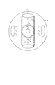
このチェーン11を駆動するための内歯をもった大型歯車10の配置を図6(a)で示す。図6(a)では外側ケース9は省略されている。円形の大型歯車10の中心は車軸歯車5の中心と一致し、2つの歯車は同心円の関係になる。大型歯車10の内歯は内側ケース8の両端に設けられたチェーンガイド7の外側に沿ってかけられたチェーン11とかみ合う。ペダル付きクランク3が回転することで大型歯車10が回転し、かみ合ったチェーン11が同じ向きに回転し、さらに、車軸歯車5も同じ向きに回転する。
An arrangement of the
チェーン11のかけ方は、図5及び図6(a)に示した態様には限定されない。チェーン11の一部を車軸歯車5に直接かけることができ、かつ、チェーン11の他の一部を大型歯車10の内歯にかけることができれば、チェーンガイド7の位置、配置個数は任意である。また、チェーンガイド7の形状も、この実施形態で説明したものには限定されない。チェーン11と接する部分でチェーン11を滑動させることができれば、どのような形状でもよい。
The manner of hanging the chain 11 is not limited to the mode shown in FIGS. 5 and 6A. If a part of the chain 11 can be directly applied to the axle gear 5 and another part of the chain 11 can be applied to the internal teeth of the
また、増速駆動機構2にはチェーン11の代わりに内歯と外歯の双方を供えたドーナツ型の歯車を使用して、ドーナツ型の歯車の内歯で車軸歯車5を駆動し、ドーナツ型の歯車の外歯で大型歯車10とかみ合うようにして、ペダルの回転力を車軸歯車5に伝達することもできる。この場合も車軸の回転中心と大型歯車の回転中心とペダル付きクランクの回転軸の回転中心が一致する。ドーナツ型の歯車の安定にはチェーンガイド7と類似のガイドが使用されるが、基本的にはチェーン11による駆動と同じである。
Further, the speed increasing
大型歯車10と車軸歯車5の歯数の組み合わせによって、ペダル付きクランク3が1回転するときの前輪1の回転数が決まる。増速するためには、大型歯車10の歯数を車軸歯車5の歯数より多くする。前輪1の直径が普及型の後輪駆動の自転車の前輪より小さくても、本増速駆動機構2によってペダル付きクランク3の1回転当たりの進行距離がペダルで直接前輪1を駆動する場合に比べ大きくなり、操縦者は楽に速度をあげることができる。
The number of teeth of the
増速駆動機構2は、チェーン11をチェーンガイド7により大型歯車10の内歯と車軸歯車5にかけることができるように位置決めし、大型歯車10と一体となっているペダル付きクランク3の回転を車軸歯車5に伝達するように構成され、車軸5aの回転軸と大型歯車11の回転軸とペダル付きクランク3の回転軸は一致している。そのため、力学的に安定し、操縦者がペダル付きクランク3を上から下方向に回したときに生じる下向きの力を効果的に吸収でき安定性と安全性が向上し、操縦者に与える不安定感を無くすことができる。これは、増速駆動機構2を自転車の前輪に適用する場合に顕著である。また、チェーン11を介して大型歯車10の回転を車軸歯車5に伝達することによって、歯車同士を直接かみ合わせる場合に比べ車軸歯車5上で駆動力が伝達される領域が広がり、各パーツへの負荷が分散され安全性も増す。特にチェーン11を図5のように垂直方向に渡した場合は、大型歯車10とのかみ合わせ、及び、チェーン11の動きが重力の効果で強くなり、効果的な駆動力が得られる。
The speed increasing
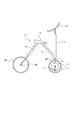
この増速駆動機構2を前輪1に取り付けた自転車17の外観を図7に示す。自転車17は、ハンドル12a、フォーク12b、これらを保持するヘッドチューブ12、増速駆動機構2を取り付けた前輪1、シートチューブ13、シートステイ14、後輪14a、操縦者が腰掛けるサドル15を備えている。自転車のフレーム構造として一般的なダイヤモンドフレームではシートチューブの下端は、サドルの下方のやや前輪よりに位置するボトムブラケットシェルでチェーンステイ及びダウンチューブと接続される。しかし、自転車17では、シートチューブ13の上端はサドル15に、下端はヘッドチューブ12のフォーク出口12c付近に接続されている。シートステイ14は、上端をサドル15に、下端を後輪の軸部14bに接続されている。
FIG. 7 shows the appearance of a
このような構成としたため、自転車17のフレーム構造からトップチューブ、ダウンチューブ、及び、チェーンステイを省くことができる。また、通常の後輪駆動式の自転車であればサドルの下方に設けられるペダルで後輪を駆動するために必要なチェーンも不要になる。ただし、構造の強度を保つために、フレームパイプ(シートチューブ13とシートステイ14)には強度の十分なものを使用する必要があるが、最近の素材技術の進歩により、そのようなフレームパイプも安価に製造できる。
With such a configuration, the top tube, the down tube, and the chain stay can be omitted from the frame structure of the
そのため、フレーム構造を簡素化することができ、製造の際に部品数の減少と工数の削減を図ることができる。また、折り畳みの機構を付加する場合にも、後輪駆動用のチェーンやダウンチューブの処理方法を考慮する必要が無く、簡単な構造の折り畳み機構で足りる。たとえば、シートチューブ13とサドル15の連結部及びシートステイ14とサドル15の連結部をそれぞれロック可能なヒンジ構造とすれば、上記二つ連結部を回転させて前輪1と後輪14aの間隔を狭めるように折りたたむことができる。
Therefore, the frame structure can be simplified, and the number of parts and man-hours can be reduced during manufacturing. Also, when a folding mechanism is added, it is not necessary to consider the rear wheel drive chain or down tube processing method, and a folding mechanism with a simple structure is sufficient. For example, if the connecting portion between the
増速駆動機構2は、自転車に限らず車輪をクランクやペダル等で駆動する乗り物一般に適用することができる。たとえば、車いすに適用する場合には、左右の車輪のそれぞれ外側に増速駆動機構2を設けるようにすればよい。
The speed increasing
1・・・前輪、2・・・増速駆動機構、3・・・ペダル付きクランク、4・・・ペダル付きクランクの回転軸、5・・・車軸歯車、5a・・・車軸、6・・・車軸貫通用のホール、7・・・チェーンガイド、8・・・内側ケース、9・・・外側ケース、10・・・大型歯車、10a・・・スポーク、11・・・チェーン、12・・・ヘッドチューブ、12a・・・ハンドル、12b・・・フォーク、12c・・・フォーク出口、12d・・・増速駆動機構の取り付け板、12e・・・車軸受けとなるホール、12f・・・フォーク側のネジ穴、12g・・・内側ケースのネジ穴、13・・・シートチューブ、14・・・シートステイ、14a・・・後輪、14b・・・後輪の軸部、15・・・サドル、16・・・ケース、17・・・自転車 DESCRIPTION OF SYMBOLS 1 ... Front wheel, 2 ... Speed-up drive mechanism, 3 ... Crank with pedal, 4 ... Rotating shaft of crank with pedal, 5 ... Axle gear, 5a ... Axle, 6 ...・ Hole for axle penetration, 7 ... Chain guide, 8 ... Inner case, 9 ... Outer case, 10 ... Large gear, 10a ... Spoke, 11 ... Chain, 12 ... Head tube, 12a ... handle, 12b ... fork, 12c ... fork outlet, 12d ... speed increasing drive mechanism mounting plate, 12e ... axle bearing hole, 12f ... fork Screw hole on the side, 12g ... Screw hole in the inner case, 13 ... Seat tube, 14 ... Seat stay, 14a ... Rear wheel, 14b ... Shaft part of the rear wheel, 15 ... Saddle, 16 ... case, 17 ... bicycle
Claims (4)
Priority Applications (1)
| Application Number | Priority Date | Filing Date | Title |
|---|---|---|---|
| JP2008008815U JP3148769U (en) | 2008-12-16 | 2008-12-16 | Speed increase drive mechanism, bicycle with speed increase drive mechanism, wheelchair with speed increase drive mechanism |
Applications Claiming Priority (1)
| Application Number | Priority Date | Filing Date | Title |
|---|---|---|---|
| JP2008008815U JP3148769U (en) | 2008-12-16 | 2008-12-16 | Speed increase drive mechanism, bicycle with speed increase drive mechanism, wheelchair with speed increase drive mechanism |
Publications (1)
| Publication Number | Publication Date |
|---|---|
| JP3148769U true JP3148769U (en) | 2009-02-26 |
Family
ID=54782289
Family Applications (1)
| Application Number | Title | Priority Date | Filing Date |
|---|---|---|---|
| JP2008008815U Expired - Fee Related JP3148769U (en) | 2008-12-16 | 2008-12-16 | Speed increase drive mechanism, bicycle with speed increase drive mechanism, wheelchair with speed increase drive mechanism |
Country Status (1)
| Country | Link |
|---|---|
| JP (1) | JP3148769U (en) |
-
2008
- 2008-12-16 JP JP2008008815U patent/JP3148769U/en not_active Expired - Fee Related
Similar Documents
| Publication | Publication Date | Title |
|---|---|---|
| JP2009012627A (en) | Hub for motor-driven wheel, and vehicle provided with the hub | |
| US20150217833A1 (en) | Bicycle with electric motor assist | |
| US20160304149A1 (en) | Tricycle with two riding modes | |
| US20220348286A1 (en) | Rear sprocket assembly and lock device | |
| US8382140B2 (en) | Reconfigurable wheeled cycle | |
| JP6941388B2 (en) | bicycle | |
| JP3148769U (en) | Speed increase drive mechanism, bicycle with speed increase drive mechanism, wheelchair with speed increase drive mechanism | |
| JP4807644B2 (en) | bicycle | |
| JP2020050043A (en) | Three-wheel bicycle | |
| JP2008224020A (en) | Differential device for tricycle | |
| KR20170106788A (en) | Wheel Motor Assembly for electric bicycle | |
| KR20100134950A (en) | Handsfree cycle | |
| JP7142266B2 (en) | Electric bicycle | |
| GB2467624A (en) | Bicycle convertible into a tricycle or quadracycle | |
| JP2009119990A (en) | Chainless bicycle | |
| JP2013001145A (en) | Vehicle for children | |
| JP4310575B2 (en) | Power transmission method and apparatus | |
| KR200306897Y1 (en) | An eccentric wheel | |
| KR100837445B1 (en) | Steering mechanism for four wheeled cycle | |
| KR100781765B1 (en) | One-seat two-wheel drive type four-wheeled cycle for advertisement and publicity work | |
| KR200420087Y1 (en) | Bicycles with fork all-wheel steering | |
| KR20070106182A (en) | Multi bicycle | |
| JP3156374U (en) | Electric vehicle equipment | |
| KR20150090670A (en) | Four wheel bi-cycle | |
| KR101749695B1 (en) | bicycle |
Legal Events
| Date | Code | Title | Description |
|---|---|---|---|
| R150 | Certificate of patent or registration of utility model |
Free format text: JAPANESE INTERMEDIATE CODE: R150 |
|
| FPAY | Renewal fee payment (event date is renewal date of database) |
Free format text: PAYMENT UNTIL: 20120204 Year of fee payment: 3 |
|
| LAPS | Cancellation because of no payment of annual fees |