JP3148317U - Drilling discharge device for trial drilling - Google Patents
Drilling discharge device for trial drilling Download PDFInfo
- Publication number
- JP3148317U JP3148317U JP2008008239U JP2008008239U JP3148317U JP 3148317 U JP3148317 U JP 3148317U JP 2008008239 U JP2008008239 U JP 2008008239U JP 2008008239 U JP2008008239 U JP 2008008239U JP 3148317 U JP3148317 U JP 3148317U
- Authority
- JP
- Japan
- Prior art keywords
- pressure air
- soil
- bucket
- excavation
- air cylinder
- Prior art date
- Legal status (The legal status is an assumption and is not a legal conclusion. Google has not performed a legal analysis and makes no representation as to the accuracy of the status listed.)
- Expired - Lifetime
Links
Images

Landscapes
- Earth Drilling (AREA)
Abstract
【課題】地中埋設物を探査するために土壌に向かって簡易な実施方法で高圧エアーを噴射して土壌を破砕した排土を穴より排出することで、本掘り前の試掘穴を手掘りして探査する労力の削減と手掘りの時間を容易に短縮可能とする試掘用採掘削排出装置を提供する。【解決手段】コンプレッサーに接続した圧力エアーホースを介して接続した圧力エアー管の周囲に高温を遮断する耐熱性保護カバーを設け、圧力エアー管の先端部にノズルを設けて掘削部を構成し、エアシリンダー2とエアシリンダーを操作する開閉バルブ3を軸4の上端部に設け、その軸の下端部にはバケット開閉アーム11を介して開閉するバケット5を設けて、中に延長ロッドを通すことができる穴を有する軸4の中に通した延長ロッド10の上端部を前記エアシリンダーのピストンロッドに接続して先端部をバケットの開閉アームの関節部に接続して、開閉バルブ3の操作によりバケットを開閉させる。【選択図】図1[PROBLEMS] To manually excavate a test hole before main digging by discharging high-pressure air toward the soil by expelling high-pressure air toward the soil and expelling the soil crushed from the hole. Provided is a sampling excavation / exhaust device for exploration that makes it possible to reduce exploration labor and easily reduce manual digging time. A heat-resistant protective cover that blocks high temperature is provided around a pressure air pipe connected via a pressure air hose connected to a compressor, and a nozzle is provided at the tip of the pressure air pipe to form an excavation part. An air cylinder 2 and an opening / closing valve 3 for operating the air cylinder are provided at the upper end portion of the shaft 4, and a bucket 5 that is opened and closed via a bucket opening / closing arm 11 is provided at the lower end portion of the shaft, and an extension rod is passed therethrough. The upper end portion of the extension rod 10 passed through the shaft 4 having a hole capable of being connected is connected to the piston rod of the air cylinder and the tip end portion is connected to the joint portion of the opening / closing arm of the bucket. Open and close the bucket. [Selection] Figure 1
Description
本考案は、電柱穴を本堀する前に地中埋設物の損傷を避けるため、試掘穴を掘削し、試掘の際に破砕した排土を穴の外部に排出することが容易な掘削排出装置に関するものである。 The present invention is an excavation and discharge device that makes it easy to excavate a test hole and discharge the crushed soil to the outside of the hole in order to avoid damaging underground objects before main drilling the utility pole hole It is about.
地中には、ガス管、水道管、光ケーブル、電力線、電話線などが埋設されている場合があり、土壌に電柱を立てる場合には電柱間隔を開けて工事箇所ごとにそれらの地中埋設物を損傷しないように本掘り前の試験堀りをするとか、或いはその他の方法で地中埋設物の
確認探査をすることが必要である。作業員がその電柱設置工事前に試掘穴を掘削、地中埋設物の深さ、種類、大きさ、形状を確認する作業を行っている。その試掘穴を掘削する場合には、しょうれん、スコップ、ひしゃく等を用い、直径40cm深さ150cmの試掘穴を掘るために、健康な人が2名で一組となって労力と3〜4時間をかけて行い、1日で3〜4本の試掘穴を手掘りをすることが行われている。
しかし、体力が弱い人であっても2名の作業員が機械を用いて試掘すると、1本の試掘穴を30分〜1時間で作業を完了させることが出来るようになるので1日で5〜6本の試験堀が可能である。
この結果として前記のように手掘りをする場合に比べれば、機械掘りは、健康な人にとっても、体力が弱い人にとっても作業を手早くすることが可能になり、1日に2本の試験掘の差は経済的にも有利になる。例えば、試験掘の差を1日に2本としてこれを経済価値に換算してみると金銭的にも2〜3万円の差額になるので、その労力と時間を大幅に節約することが出来る。
There are cases where gas pipes, water pipes, optical cables, power lines, telephone lines, etc. are buried in the ground. When installing utility poles in the soil, the underground poles are installed at each construction site with a spacing between the utility poles. It is necessary to conduct a test excavation prior to the main excavation so as not to damage the ground, or to confirm the exploration of underground objects by other methods. Workers are excavating a test hole before the utility pole installation work, and confirming the depth, type, size, and shape of the underground object. When digging the digging hole, using wells, scoops, ladle, etc., and digging a digging hole with a diameter of 40cm and a depth of 150cm, two healthy people will work together to make 3-4 It takes time to dig 3 to 4 test holes in one day.
However, even if the person is weak, if two workers use the machine to make a test, one work hole can be completed in 30 minutes to 1 hour. ~ 6 test moats are possible.
As a result, compared to the case where manual digging is performed as described above, mechanical digging can be performed quickly both for healthy people and those with weak physical strength. This difference is also economically advantageous. For example, if the difference in test digging is two per day and converted to economic value, the difference will be 20,000 to 30,000 yen in monetary terms, which can save a lot of labor and time. .
地中埋設物を損傷させることなく電柱設置工事を行うために、土壌表面に向けて圧縮空気若しくは圧縮空気と高圧水の混合流体を噴射して土壌を掘削破壊すると共に、該破砕された土壌を吸引ホースにより吸引移送して排土する方法(特許文献4の特許請求の範囲請求項6)が行われている。探査掘削と排土を同時に行う探査掘削方法(特許文献5)、正負の空気圧を利用して土壌を粉砕することを目的とする空気式土壌掘削装置(特許文献8,9)、地表面の平面の図面情報をイメージスキャナによって読み取って得た画像にキーボードなどの入力手段によって地中埋設物の位置及び現場周辺の試掘などの観察による情報を入力し、希望する予め定める位置の第1断面画像を切り出して作成し、地中の3次元データと電磁波を用いて地表面をあらかじめ定める位置で走査して地中の第2断面画像を探査して、第1断面画像と第2断面画像を重ね合わせることによってこれらの何れにも重なって表示される像を地中埋設管の像であるものとして地中埋設物の検出方法及び検出装置(特許文献6)、地中埋設物を損傷させることなく探査掘削するために、水力掘削の方法によって探査孔を形成する最も安全な方法(特許文献2) などがある。
これらの先行技術の内で特許文献4は地中埋設物に損傷を与えることなく、圧縮空気又は圧縮空気と高水圧を利用して土壌の掘削と破砕をし、それによって発生する排土を吸引装置によって排出することができる利点があるので実用化されている。
In order to perform utility pole installation work without damaging the underground objects, the compressed air or a mixed fluid of compressed air and high-pressure water is jetted toward the soil surface to excavate and destroy the soil, and the crushed soil A method of sucking and transferring soil by a suction hose (
Among these prior arts,
しかしながら、特許文献4によれば電柱工事を施工するために圧縮空気の発生装置と破砕した排土を排出する吸引装置が必要であるから、その発明装置は試験堀りを行う装置としては大掛かりになるので、電柱工事のための本掘り前に行う試掘穴を掘削して、地中に埋設物があるかないかの確認作業を本掘りの前に行う場合には適当ではない。
However, according to
本考案は、電柱工事の設置穴を本掘りする前に地中埋設物の確認探査を行いその試験掘りをした穴の中から排土を排出することを目的とするものであって、このためコンプレッサーを用いて高圧エアーを利用して試掘穴を掘削する作業(試験掘りするという。)を行い、同時にそのコンプレッサーを用いて高圧エアーを利用して破砕された排土を排出して、電柱工事を行う作業者の労力を軽減し、時間を節減して健康な人も、力が弱い人にも2名で一組になってそれを効率的に実施することができるようにしようとするものである。 The purpose of the present invention is to confirm the exploration of underground objects before excavating the installation holes for utility pole construction, and to discharge the soil from the holes excavated in the test. Work to drill a test hole using high-pressure air using a compressor (referred to as test digging), and simultaneously discharge the crushed soil using high-pressure air using the compressor, To reduce the labor of the workers who do the work, to save time, so that healthy people and weak people can work together as a set with two people efficiently It is.
電柱設置工事の際には地中埋設物の確認をしないで掘削すると地中埋設物を損傷させたりするので、電柱設置工事を中断せざるを得ないなどの問題があった。 There was a problem that the utility pole installation work had to be interrupted because excavation without confirming the underground buried object would damage the underground buried object during the utility pole installation work.
この改善策として、土壌に圧縮エアーを噴射して破砕する掘削、圧縮空気と水流の混合流体を噴射して土壌を破砕し掘削する方法がある。手作業で試掘穴を掘削したり、電磁波を利用して地中埋設物をあらかじめ探査した後に掘削する方法がある。破砕された排土の排出には、吸引して吸引ホースから外部運搬車へ移送する方法がある。
解決しようとする問題点は、電柱穴を掘削して電柱を立てる前に地中埋設物の確認探査をするために試掘穴を掘削する手掘り操作において障害となる土壌の掘削と排土の排出を簡易な方法ですばやくできない点である。土壌中にある地中埋設物を探査する試掘穴を簡易な実施方法で掘削するために、コンプレッサーに接続してあるエアーホースを接続した圧力エアー管の先端に高圧エアーを土壌に向けて噴射するノズルを設けた掘削部を有する掘削装置と、土壌に高圧エアーを噴射して破砕した排土を試掘穴より排出するため、コンプレッサーに接続してある圧力エアーホースを開閉バルブを介してエアーシリンダーに接続し、該エアーシリンダーのピストンロッドに延長ロッドを接続し、それを軸の中に通してその先端に開閉アームを接続し、高圧エアーを利用してエアシリンダーのピストンを駆動して、ピストンロッドの延長ロッドを軸先端の開閉アームに接続してあるバケットを開閉して、バケットで排土を掴み取り出す排出装置とを組み合わせてなる掘削排出装置で本掘り前の試験堀を行って排土を排出して地中埋設物を探査することを可能とする。この問題点の解決方法は、地中埋設物を損傷させることなく、健康な人にも、力の弱い人にとっても作業に従事している人の労力の削減と手掘りの時間を容易に短縮できる。 The problem to be solved is the excavation of soil and the discharge of soil that becomes an obstacle in the manual digging operation to excavate the test hole to confirm the underground exploration before excavating the utility pole hole and standing the utility pole It is a point that cannot be done quickly with a simple method. In order to excavate a test hole for exploring underground objects in the soil with a simple implementation method, high pressure air is sprayed toward the soil at the tip of a pressure air pipe connected to an air hose connected to a compressor. In order to discharge the excavation equipment that has the excavation part provided with the nozzle and high pressure air to the soil and discharge the crushed soil from the test hole, the pressure air hose connected to the compressor is connected to the air cylinder via the open / close valve Connect the extension rod to the piston rod of the air cylinder, pass it through the shaft, connect the open / close arm to the tip, drive the piston of the air cylinder using high pressure air, and the piston rod Opening and closing the bucket that connects the extension rod of the shaft to the opening and closing arm at the end of the shaft, combined with a discharge device that grabs the soil with the bucket In cutting discharge device performing the digging prior to testing moat to drain soil discharge makes it possible to explore underground buried object. The solution to this problem reduces the labor and time of digging easily for healthy and weak people, without damaging underground objects. it can.
本考案は、コンプレッサーに接続してある圧力エアーホースを接続した圧力エアー管の先端に高圧エアーを土壌に向けて噴射するノズルを設けた掘削部を有する掘削装置と、土壌を掘削した排土を試掘穴より排出するため、コンプレッサーに接続してある圧力エアーホースを開閉バルブを介してエアーシリンダーに接続し、該エアーシリンダーロッドの延長ロッドを軸の中に通してその先端を開閉アームに接続し、開閉バルブを操作して高圧エアーを利用して開閉アームに設けたバケットを開いて、バケットで排土を掴み取り出す排出装置とを組み合わせて地中埋設物を損傷させることなく試験堀りすることが容易な掘削排出装置である。電柱穴の本掘りの前に試験堀をするため、作業者は、コンプレッサーに接続してある圧力エアーホースを接続した圧力エアー管の先端部に接続したノズルより高圧エアーを土壌に向かって噴射して破砕し、破砕した排土を排出するバケットとバルブを開閉する操作でバケットを開閉させるエアーシリンダーを軸に設け、圧力エアーホースを接続した開閉バルブの操作により前記エアシリンダーのピストンを駆動可能とすることを最も主要な特徴とする。 The present invention provides a drilling device having a drilling unit provided with a nozzle for injecting high-pressure air toward the soil at the tip of a pressure air pipe connected to a pressure air hose connected to a compressor, and a drainage excavated from the soil. In order to discharge from the borehole, the pressure air hose connected to the compressor is connected to the air cylinder via the open / close valve, the extension rod of the air cylinder rod is passed through the shaft, and the tip is connected to the open / close arm. , Open the bucket provided on the open / close arm using high pressure air by operating the open / close valve, and combine it with the discharge device to grab the soil with the bucket and drill the test without damaging the underground objects Is an easy excavation and discharge device. In order to conduct a test excavation before the main drilling of the utility pole hole, the operator injects high-pressure air toward the soil from the nozzle connected to the tip of the pressure air pipe connected to the pressure air hose connected to the compressor. The air cylinder that opens and closes the bucket by opening and closing the valve by opening and closing the valve and the valve that opens and closes the valve by operating the opening and closing valve connected to the pressure air hose can drive the piston of the air cylinder Doing is the main feature.
コンプレッサーに接続した圧力エアーホースを介して接続した圧力エアー管の周囲に高温を遮断する耐熱性保護カバーを設け、圧力エアー管の先端部に土壌に向かって高圧エアーを噴射するノズルを設けて掘削部を構成し、土壌に向かってノズルより噴射した高圧エアーで直径40cm深さ150cmの試掘穴を掘削し、試掘穴から排土を取り出すため、エアーシリンダーとエアーシリンダーを操作する開閉バルブを軸上端部に設け、その軸の下端部にはバケット開閉アームを介して開閉するバケットを設けて、軸中に延長ロッドを通すことができる穴を有する軸の中に通した延長ロッドの上端部を前記エアシリンダーのピストンロッドに接続して先端部をバケットの開閉アームの関節部に接続して、開閉バルブの操作によりピストンを駆動してバケットを開閉させ試掘穴の排土を排出することを特徴とする。 Drilling by providing a heat-resistant protective cover that blocks high temperature around the pressure air pipe connected via a pressure air hose connected to the compressor, and a nozzle that injects high-pressure air toward the soil at the tip of the pressure air pipe The upper end of the shaft is an open / close valve that operates the air cylinder and the air cylinder in order to excavate a test hole with a diameter of 40 cm and a depth of 150 cm with high-pressure air jetted from a nozzle toward the soil. The upper end of the extension rod passed through the shaft having a hole through which the extension rod can be passed is provided in the lower end portion of the shaft. Connect the piston rod of the air cylinder, connect the tip to the joint of the bucket open / close arm, and drive the piston by operating the open / close valve Characterized by discharging the dumping of bore hole is opened and closed the bucket Te.
本考案の試掘穴の掘削排出装置は、1台のコンプレッサーに圧力エアーホースをそれぞれ接続してある掘削装置と排出装置とを組み合わせて使用し、掘削装置と排出装置とは同一のコンプレッサーに接続した圧力エアーホースから送られる高圧エアーで駆動し、それぞれ軽量であるから、2名の作業者で掘削と排出を協力しあって作業を行うことが出来るようにしたので、健康な作業者にとっても、力が弱い体の作業者にとっても2名で使えるという利点がある。 The drilling and discharging device of the test hole of the present invention uses a combination of a drilling device and a discharging device each having a pressure air hose connected to one compressor, and the drilling device and the discharging device are connected to the same compressor. Because it is driven by high-pressure air sent from the pressure air hose and each is lightweight, it was possible for two workers to cooperate in excavation and discharge, so even for healthy workers, There is an advantage that it can be used by two workers even for weak workers.
電柱工事のための本掘り前に2名一組で試掘穴を掘削して排土を排出できるようにして地中埋設物を損傷させることなく確認工事をするという目的を、最小の掘削装置と排出装置の組み合わせからなる軽量な部品で構成される装置で、健康な作業者にとっても、力が弱い体の作業者にとっても労力を軽減し、時間を短縮して試験堀の作業効率を損なわずに実現した。 Before the main digging for the utility pole construction, a group of two people excavated a test hole to discharge the soil, and the purpose of confirming work without damaging underground buried objects was A device composed of lightweight parts consisting of a combination of discharge devices, reducing labor for healthy workers and weak workers, saving time and reducing the work efficiency of the test moat Realized.
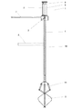
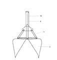
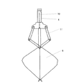
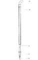
本考案装置の実施例を示しており、図1は、本考案装置の実施例1に説明する排出装置1のバケットの実施方法を示す正面図であって、図2は実施例1に説明する排出装置のバケットを開いた実施方法、図3は実施例1に説明する排出装置のバケットを閉じた実施方法を示す。図6は電柱用設置穴と土壌に高圧エアーを噴射して掘削した試掘穴を示す断面図である。電柱穴18を掘削して電柱を立てる前に地中埋設物を確認探査するために試掘穴17を掘削する。
1 shows an embodiment of the device of the present invention, and FIG. 1 is a front view showing a method for carrying out the bucket of the
コンプレッサーに接続してある圧力エアーホース7を接続した開閉バルブ3を介してエアーシリンダー2に接続し、該エアーシリンダーのピストンロッド9の延長ロッド10を軸4の中に通してその先端を開閉アーム11に接続し、開閉アーム11を介してバケット5を設けた。この排出装置の構成により、作業者は開閉バルブのレバー操作を行いエアーシリンダーのピストン8を駆動させて、ピストンロッド9に接続した延長ロッド10で開閉アームを介してバケット5を開いて、高圧エアーを利用してバケットで排土を掴み取り出す排出装置である。
Connected to the
この排出装置の使用方法は、圧力エアーホース7をコンプレッサーに接続して、開閉レバーで排出装置のバルブの操作を行うことで、軸4の上端部に設けたエアーシリンダー2のピストンが駆動して開閉アーム11を介してバケット5を開閉させる排出装置である。
This discharge device is used by connecting a pressure air hose 7 to a compressor and operating the valve of the discharge device with an opening / closing lever, so that the piston of the
軸4には握り手ハンドル6を2箇所に設ける場合がある。握り手ハンドルのグリップは作業者が着脱容易にして、任意な位置に付け替えることができるようにするなどの工夫により作業者が操作しやすいように変更使用する効果がある。
The
図4は実施例2に説明する掘削装置の実施方法を示す正面図、図5は実施例2に説明する掘削装置の実施方法を示す断面図である。図4,5の実施例は、高圧エアーを使用するため掘削の際に地中の埋設物に損傷を与えないで試掘穴を掘削することが第一の条件と成っている。
コンプレッサーに接続した圧力エアーホース12は圧力エアー管13の上端部に接続されており、圧力エアー管13は発熱するのでそれには耐熱性保護カバー14が設けられ、作業者は断熱性の保護カバーで保護されている。圧力エアー管13の先端部に土壌19に向かって高圧エアーを噴射するノズル16を設け、ノズル16には保護カバー15を設けた。
FIG. 4 is a front view illustrating a method for implementing the excavator described in the second embodiment, and FIG. 5 is a cross-sectional view illustrating a method for implementing the excavator described in the second embodiment. In the embodiment of FIGS. 4 and 5, since the high pressure air is used, it is the first condition that the test hole is excavated without damaging the underground object during excavation.
The
実施例2の掘削装置は、上記のようにコンプレッサーに接続してある圧力エアーホース12を接続した圧力エアー管13の先端に高圧エアーを土壌に向けて噴射するノズル16を設けた掘削部を有する掘削装置である。この掘削装置により高圧エアーを土壌に向かって噴射して掘削し、破砕した排土を試掘穴より排出するため、実施例1に詳細に説明した排出装置の圧力エアーホース7をコンプレッサーに接続して、開閉バルブ3を操作してエアーシリンダー2のピストン8を駆動して、ピストンロッド9の延長ロッドを軸4の中を通して接続した開閉アーム11を介してバケットで5排土を掴み取り出す排出装置とを組み合わせて使用することができる掘削排出装置である。
The excavation apparatus of Example 2 has an excavation part provided with a
この圧力エアーホース7,12を1台のコンプレッサーに接続して、図1〜3に実施例1を示す排出装置1と図4,5に実施例2を示す掘削装置とは組み合わせて2名の作業員が掘削装置と排出装置の操作を行うことで、地中埋設物を損傷させることなく、土壌の中に試掘穴17を試験堀りすることが容易な掘削排出装置である。
These
本考案の掘削排出装置で電柱設置工事の本掘り前の試験堀を行う場合には、以上に記述した実施方法により土壌中に地中埋設物を探査する目的で試験掘りを簡易な実施方法で行うために、手掘りしていたしょうれん、スコップ、ひしゃくに代えて、操作が簡単で軽量な掘削装置そして排出装置により労力的にも軽減されて、健康な人にも、力の弱い人にとっても2名一組で協力して地中埋設物を損傷させることなく、直径40cm深さ150cmの試掘穴を掘削できて確実な探査をしてそこに電柱を設置する用途に適用することが出来る。 When conducting a test excavation prior to the main excavation of the utility pole installation work with the excavation and discharge device of the present invention, the test excavation can be conducted with a simple implementation method for the purpose of exploring underground objects in the soil by the implementation method described above. In order to do so, instead of digging soy sauce, scoop and ladle, it is reduced in labor by a simple and lightweight drilling rig and discharge device, so that both healthy and weak people It is possible to excavate a test hole with a diameter of 40 cm and a depth of 150 cm without damaging underground objects by cooperating with a set of two people, and it can be applied to the purpose of installing a utility pole in a reliable exploration. .
1 排出装置全体
2 エアーシリンダー
3 開閉バルブ
4 軸
5 バケット
6 握り手ハンドル
7 圧力エアーホース
8 ピストン
9 ピストンロッド
10 延長ロッド
11 バケット開閉アーム
12 圧力エアーホース
13 圧力エアー管
14,15 保護カバー
16 ノズル
17 試掘穴
18 電柱穴
19 土壌
DESCRIPTION OF
Claims (3)
Priority Applications (1)
| Application Number | Priority Date | Filing Date | Title |
|---|---|---|---|
| JP2008008239U JP3148317U (en) | 2008-11-25 | 2008-11-25 | Drilling discharge device for trial drilling |
Applications Claiming Priority (1)
| Application Number | Priority Date | Filing Date | Title |
|---|---|---|---|
| JP2008008239U JP3148317U (en) | 2008-11-25 | 2008-11-25 | Drilling discharge device for trial drilling |
Publications (1)
| Publication Number | Publication Date |
|---|---|
| JP3148317U true JP3148317U (en) | 2009-02-12 |
Family
ID=54781877
Family Applications (1)
| Application Number | Title | Priority Date | Filing Date |
|---|---|---|---|
| JP2008008239U Expired - Lifetime JP3148317U (en) | 2008-11-25 | 2008-11-25 | Drilling discharge device for trial drilling |
Country Status (1)
| Country | Link |
|---|---|
| JP (1) | JP3148317U (en) |
Cited By (1)
| Publication number | Priority date | Publication date | Assignee | Title |
|---|---|---|---|---|
| JP2019199686A (en) * | 2018-05-14 | 2019-11-21 | 大成建設株式会社 | Crusher and crushing method |
-
2008
- 2008-11-25 JP JP2008008239U patent/JP3148317U/en not_active Expired - Lifetime
Cited By (2)
| Publication number | Priority date | Publication date | Assignee | Title |
|---|---|---|---|---|
| JP2019199686A (en) * | 2018-05-14 | 2019-11-21 | 大成建設株式会社 | Crusher and crushing method |
| JP7107736B2 (en) | 2018-05-14 | 2022-07-27 | 大成建設株式会社 | Crushing device and crushing method |
Similar Documents
| Publication | Publication Date | Title |
|---|---|---|
| CN106545007B (en) | The method of pile in the stratum that lower part is hard rock stratum | |
| US11761166B2 (en) | Roadway access hole drill and a method of microtrenching using the drill to open an access hole in the roadway | |
| CN207111100U (en) | A kind of hard rock tunnel construction equipment | |
| CN107355228A (en) | A kind of hard rock tunnel construction equipment and construction method | |
| CN106245985A (en) | Hydraulic pressure electric pole pole erecting vehicle | |
| CN111877344A (en) | Old pipe pile breaking method | |
| JP3148317U (en) | Drilling discharge device for trial drilling | |
| KR100769089B1 (en) | Multi-angle Rock Drill | |
| CN104141455B (en) | Drilling rig equipment and drilling rig drilling method | |
| CN110173274A (en) | A kind of head is removed obstacles method | |
| CN202492847U (en) | High-pressure water jet casing pipe pile pulling tool | |
| CN212296280U (en) | Hydraulic impact sampling drilling machine | |
| CN112324441A (en) | Construction method for removing underground shield segments by full-slewing drilling machine | |
| KR100880365B1 (en) | Expansion Excavation Excavator for Underwater Installation of Underwater Structures for Industrial Facilities | |
| EP4417755A1 (en) | Vacuum excavation for local transmission system and method | |
| CN120231590A (en) | Deep formation liquid-filled well controllable shape mining system and mining method | |
| US20120261113A1 (en) | Cobble/small boulder debris device in borehole excavating | |
| JP2003027469A (en) | Steel pipe pile, foundation pile producing method using the same and device of the method | |
| JP5819736B2 (en) | Steel pipe pile for excavation | |
| JP2001082062A (en) | Underground confirmation device | |
| JP3155967U (en) | Glove holding device | |
| CN110030006A (en) | There is the shield tunneling method of a large amount of boulders by saturated sand and in layer of sand | |
| CN205830355U (en) | A kind of Rhizoma Dioscoreae excavator | |
| JP3139410U (en) | Prospecting machine | |
| JP2003253982A (en) | Annular excavator |
Legal Events
| Date | Code | Title | Description |
|---|---|---|---|
| R150 | Certificate of patent or registration of utility model |
Free format text: JAPANESE INTERMEDIATE CODE: R150 |
|
| FPAY | Renewal fee payment (event date is renewal date of database) |
Free format text: PAYMENT UNTIL: 20120121 Year of fee payment: 3 |
|
| FPAY | Renewal fee payment (event date is renewal date of database) |
Free format text: PAYMENT UNTIL: 20150121 Year of fee payment: 6 |
|
| R250 | Receipt of annual fees |
Free format text: JAPANESE INTERMEDIATE CODE: R250 |
|
| R250 | Receipt of annual fees |
Free format text: JAPANESE INTERMEDIATE CODE: R250 |
|
| R250 | Receipt of annual fees |
Free format text: JAPANESE INTERMEDIATE CODE: R250 |
|
| EXPY | Cancellation because of completion of term |