JP3146527U - Dump truck - Google Patents
Dump truck Download PDFInfo
- Publication number
- JP3146527U JP3146527U JP2008006330U JP2008006330U JP3146527U JP 3146527 U JP3146527 U JP 3146527U JP 2008006330 U JP2008006330 U JP 2008006330U JP 2008006330 U JP2008006330 U JP 2008006330U JP 3146527 U JP3146527 U JP 3146527U
- Authority
- JP
- Japan
- Prior art keywords
- concrete
- dump truck
- loading platform
- discharge port
- accommodating portion
- Prior art date
- Legal status (The legal status is an assumption and is not a legal conclusion. Google has not performed a legal analysis and makes no representation as to the accuracy of the status listed.)
- Expired - Lifetime
Links
Images


Landscapes
- On-Site Construction Work That Accompanies The Preparation And Application Of Concrete (AREA)
Abstract
【課題】拡張レヤ工法に用いられるコンクリートを効率よく運搬することができ、コンクリートを排出する際に、所定の高さ以上に容易に積み上げることが可能なダンプトラックを提供する。
【解決手段】上方にコンクリートSが流し込まれる開口部24を有し、車両本体12の後方側にコンクリートSを排出する排出口26を有するコンクリート収容部18が設けられた荷台16を備える。荷台16を前後方向に傾斜させる傾動機構を有し、荷台16を傾動させることによって、コンクリート収容部18内のコンクリートSを排出口26から車両本体12の後方に排出する。コンクリート収容部18の底部から排出口26にかけて、地面に対して上向きの傾斜角度を有する傾斜面18cを備え、排出口26は、コンクリートSを排出するために荷台16を最大に傾動させたときも、拡張レヤ工法によるコンクリート打設高さよりも高い位置に位置する。
【選択図】図1Provided is a dump truck that can efficiently transport concrete used in an extended layer construction method, and can be easily stacked above a predetermined height when discharging concrete.
A loading platform 16 is provided which has an opening 24 into which concrete S is poured upward, and a concrete receiving portion 18 having a discharge port 26 for discharging the concrete S on the rear side of a vehicle body 12. A tilting mechanism for tilting the loading platform 16 in the front-rear direction is provided. By tilting the loading platform 16, the concrete S in the concrete accommodating portion 18 is discharged from the discharge port 26 to the rear of the vehicle body 12. An inclined surface 18c having an upward inclination angle with respect to the ground is provided from the bottom of the concrete accommodating portion 18 to the discharge port 26, and the discharge port 26 is also inclined when the loading platform 16 is tilted to the maximum in order to discharge the concrete S. It is located at a position higher than the concrete placement height by the extended layer method.
[Selection] Figure 1
Description
この考案は、コンクリートダムの建設等に用いられるダンプトラックに関し、特に拡張レヤ工法用のコンクリートの運搬に使用されるダンプトラックに関する。 The present invention relates to a dump truck used for construction of a concrete dam, and more particularly to a dump truck used for transporting concrete for an extended layer method.
コンクリートダムを建設する工法として、柱状工法の一種であるブロック工法及びレヤ工法、面状工法の一種であるRCD工法(Roller Compacted Concrete for Dam)及び拡張レヤ工法(ELCM:Extended Layer Construction Method)等が知られている。そして、近年では、中小規模コンクリートダムの施工や大規模コンクリートダムの一部の施工に適し、従来に比べて工期短縮と工費低減を図ることができる拡張レヤ工法が盛んに用いられている。 As a construction method for constructing a concrete dam, a block construction method and a layer construction method which are types of columnar construction methods, an RCD construction method (Roller Compacted Concrete for Dam) which is a kind of a planar construction method, and an extended layer construction method (ELCM) are used. Are known. In recent years, the extended layer construction method that is suitable for the construction of small and medium-sized concrete dams and part of large-scale concrete dams and that can shorten the construction period and reduce the construction cost as compared with the prior art has been actively used.
拡張レヤ工法は、施工設備などの許す範囲で極力継ぎ目を設けず、大きな範囲を一度に打設する工法である。拡張レヤ工法に用いられるコンクリートは、一般的に、有スランプのものが適している。このコンクリートは、コンクリートプラントで製造され、ダンプトラックで施工現場に運搬される。そして、ダンプトラックからコンクリートを打設場所に降ろすと、ホイルローダー等を用いて補助的に均し、バイバック等の締め固め機械で振動を与えて締め固めを行う。さらに、目地切機による目地切り、養生、打設面処理を経て次の打設を行う。この一連の作業は、段差のない複数のブロックを同時に内部振動機のみで締め固めながら打設していくため、小規模ダムや堤内構造物が多い中規模ダムなど内部コンクリートの打設面積が狭い場合に有利である。 The extended layer construction method is a construction method in which a large range is placed at a time without providing seams as much as possible in the construction equipment and the like. The concrete used for the extended layer method is generally a slumped concrete. This concrete is manufactured at a concrete plant and transported to a construction site by a dump truck. When the concrete is lowered from the dump truck to the place where it is placed, it is leveled with a wheel loader or the like, and compacted by applying vibration with a compacting machine such as a buy back. Furthermore, the next placement is performed through joint cutting, curing, and placement surface treatment by a joint cutting machine. In this series of operations, multiple concrete blocks are stepped while being compacted with only an internal vibrator at the same time, so the internal concrete placement area is small, such as small-scale dams and medium-scale dams with many dam structures. Is advantageous in some cases.
従来、コンクリートダムの建設等に用いられるダンプトラックとして、例えば、特許文献1に開示されているように、廃棄用の土砂等を運搬するための容器が荷台に着脱可能に設けられ、荷台を傾斜させたときでも容器が荷台から滑り落ちない構造を備えた土砂搬送用ダンプトラックがある。また、この容器は、底板から開口の一辺に向けて斜め上方に延びる斜面を備え、少なくとも荷台を傾斜させたときに、該斜面が荷台の底面に当接するように形成されている。
しかしながら、特許文献1の土砂搬送用ダンプトラックは、土砂等を排出するために荷台を傾斜させたとき、容器から土砂等が排出される上記開口の一辺が地面に近くなるため、荷台から排出された土砂等を高く積み上げることができないものであった。従って、一般的な拡張レヤ工法で設定されるコンクリートの打設高さ以上に土砂等を積み上げるためには、別途、土砂等を積み上げる工程を設ける必要があり、非常に面倒であった。 However, the dump truck for earth and sand conveyance of Patent Document 1 is discharged from the bed because the side of the opening from which the earth and sand are discharged from the container is close to the ground when the bed is inclined to discharge the earth and sand. It was impossible to pile up earth and sand. Therefore, in order to pile up the earth and sand etc. beyond the concrete placement height set by the general extended layer method, it is necessary to provide a separate step of pile up the earth and sand, which is very troublesome.
また、上記土砂運搬用ダンプトラックで拡張レヤ工法に用いられるコンクリートを運搬する場合、容器中のコンクリートが荷台に流出するおそれがある。従って、多量のコンクリートを効率よく運搬することができないものであった。 Moreover, when the concrete used for the extended layer construction method is transported by the dump truck for transporting earth and sand, the concrete in the container may flow out to the loading platform. Therefore, a large amount of concrete cannot be transported efficiently.
本考案は、上記背景技術に鑑みて成されたもので、拡張レヤ工法に用いられるコンクリートを効率よく運搬することができ、コンクリートを排出する際に所定の高さ以上に容易に積み上げることが可能なダンプトラックを提供することを目的とする。 The present invention has been made in view of the above-described background art, and can efficiently transport concrete used in the extended layer construction method, and can be easily stacked above a predetermined height when discharging concrete. Aims to provide a simple dump truck.
本考案は、左右一対の前輪及び後輪が設けられた車両本体と、上方にコンクリートが流し込まれる開口部を有し、前記車両本体後方側に前記コンクリートを排出する排出口を有するコンクリート収容部が設けられた荷台と、前記荷台を前後方向に傾斜させる傾動機構とを備え、前記荷台を傾動させることによって、前記コンクリート収容部内の前記コンクリートを前記排出口から前記車両本体後方に排出するダンプトラックであって、前記コンクリートは、拡張レヤ工法によるコンクリートダムの施工に用いられるコンクリートであり、前記コンクリート収容部の底部から前記排出口にかけて、地面に対して上向きの傾斜角度を有する傾斜面が形成され、前記排出口は、前記コンクリートを排出するために前記荷台を最大に傾動させたときも、拡張レヤ工法によるコンクリート打設高さよりも高い位置に在るダンプトラックである。 The present invention includes a vehicle main body provided with a pair of left and right front wheels and a rear wheel, and a concrete housing portion having an opening into which concrete is poured upward, and a discharge port for discharging the concrete on the vehicle main body rear side. A dump truck provided with a loading platform provided and a tilting mechanism for tilting the loading platform in the front-rear direction, and by tilting the loading platform, the concrete in the concrete container is discharged from the discharge port to the rear of the vehicle body. The concrete is concrete used for construction of a concrete dam by an extended layer construction method, and an inclined surface having an upward inclination angle with respect to the ground is formed from the bottom of the concrete accommodating portion to the discharge port, The discharge port is also used when the loading platform is tilted to the maximum to discharge the concrete. A dump truck located at a position higher than the concrete 設高 of by the extended Reya method.
また、前記車両本体の前記後輪よりも後方の部分は、拡張レヤ工法によるコンクリート打設高さの2分の1の高さよりも高い位置に在ることが好ましい。 Moreover, it is preferable that the rear part of the vehicle main body is located at a position higher than a half of the concrete placement height by the extended layer method.
さらに、前記コンクリート収容部は独立したコンクリート用容器からなり、前記荷台には、前記コンクリート用容器を着脱自在に固定する取り付け機構を備えるダンプトラックであってもよい。 Further, the concrete accommodating portion may be an independent concrete container, and the loading platform may be a dump truck provided with an attachment mechanism for detachably fixing the concrete container.
本考案のダンプトラックは、荷台を傾動させたときでも、荷台に設けられたコンクリート収容部の排出口が拡張レヤ工法によるコンクリート打設高さよりも高い位置に在るため、コンクリートを容易にコンクリート打設高さ以上に積み上げることができる。 In the dump truck of the present invention, even when the loading platform is tilted, the concrete outlet provided in the loading platform is located at a position higher than the concrete placement height by the extended layer method, so that the concrete can be placed easily. It can be stacked more than the installation height.
また、拡張レヤ工法に用いられるコンクリートを、簡単な構造のコンクリート収容部の形状で、効率よく運搬することができる。 Moreover, the concrete used for the extended layer construction method can be efficiently transported in the shape of a concrete receiving portion having a simple structure.
さらに、コンクリート収容部を、コンクリート用容器が荷台に着脱自在に固定される構成とすれば、拡張レヤ工法によるコンクリートダム建設に適したコンクリート運搬用のダンプトラックを、汎用のダンプトラックを用いて安価に構成することができる。 In addition, if the concrete container is configured so that the concrete container is detachably fixed to the loading platform, a dump truck for transporting concrete suitable for concrete dam construction by the extended layer method can be used at low cost using a general-purpose dump truck. Can be configured.
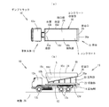
以下、この考案の一実施形態のダンプトラック10について、図1〜図3に基づいて説明する。ダンプトラック10は、図1に示すように、前方部分に運転席12aが設けられ、下面に前輪12b及び後輪12cが取り付けられた車両本体12を備えている。車両本体12の後方部分の上面には荷台16が配置され、回転軸14を介して軸着されている。荷台16は、コンクリートSを収容するコンクリート収容部18と、コンクリート収容部18を下方から支持する支持部20と、支持部20が上面に取り付けられた傾動台22とで構成されている。そして、傾動台22の下面には、車両本体12に設けられた図示しない油圧シリンダ等の傾動機構が接続され、コンクリート収容部18、支持部20及び傾動台22を、回転軸14を中心に一体に傾動させることができる。
Hereinafter, a
コンクリート収容部18は、底部18aから前方に向けて比較的急峻に立ち上がる前壁18bと、底部18aから後方にかけて斜め上向きに比較的緩慢な角度に形成された傾斜面18cと、ほぼ垂直に立ち上がる一対の側壁18dとで構成され、上方には、コンクリートSが流し込まれる開口部24と、後方には、コンクリートSを排出する排出口26が形成されている。排出口26は、荷台16を傾動させたときでも、後述するコンクリートの打設高Hよりも高い位置に在るように傾斜面18cの傾斜角度が設定されている。
The concrete accommodating
次に、拡張レヤ工法を用いたコンクリートダムの施工現場でのダンプトラック10の働きについて説明する。打設用のコンクリートは、所定の場所に設営されたコンクリートプラントで製造され、コンクリートダムの各施工現場までダンプトラック等で運搬される。拡張レヤ工法に用いられるコンクリートSは、有スランプであり、コンクリートプラントの貯蔵タンクの下方に設けられた排出口から排出され、ダンプトラック10のコンクリート収容部18に、開口部24上方から流し込まれる。コンクリートSは、図1(b)に示すように、コンクリート収容部18に形成された排出口26の下縁部26aを越えない範囲に積載される。この実施形態ではダンプトラック10は、例えば6.0m3のコンクリートを収容可能な大型のコンクリート収容部18を備えたものであり、最大積載重量が20t相当のトラックを用いる。
Next, the function of the
コンクリートSを積載したダンプトラック10は、コンクリートSを施工現場の打設場所に運搬する。そして、図2(a)に示すように、荷台16を傾動させ、後方の排出口26からコンクリートSを排出する。拡張レヤ工法では、1回の打設高Hを1.5m程度とすることが好ましく、さらに0.75m厚ずつの2層に分けて打設すると作業効率がよい。ここでは、まず1層目の打設のため、コンクリートSを地面28に排出すると、コンクリートSの流動性により約1mの高さにコンクリートSの山が形成される。このとき、ダンプトラック10の排出口26は、傾斜面18cの傾斜角度の設定によって、荷台16を傾動させたときでも、2m前後の高さに在るため、コンクリートSを排出して、地面28から約1mの高さに積み上げることは問題なく可能である。
The
コンクリートSを打設場所に降ろすと、図示しないホイルローダー等を用いて補助的に均し、図2(b)に示すように、締め固め機械であるバイバック30の振動部分30aを用いて振動を与え、締め固めを行う。一般的なバイバック30が有する締め固めの能力を考慮すると、0.75mという打設高は適切な厚さである。その後、目地切機による目地切り、養生、打設面処理を行い、1層目D1の打設工程が終了する。
When the concrete S is lowered to the placement site, it is leveled by using a wheel loader (not shown) and the like, and as shown in FIG. 2 (b), it vibrates using the
次に、1層目D1の上面に、0.75m厚の2層目D2を打設する。まず、1層目D1と同様に、ダンプトラック10は、コンクリートSを打設場所に運搬し、図3(a)に示すように、荷台16を傾動させ、後方の排出口26からコンクリートSを排出する。ここでは、2層目D2を打設するため、コンクリートSを1層目D1の上面から約1mの高さ、すなわち、地面28から約1.75mの高さに積み上げられる。ダンプトラック10の排出口26は、傾斜面18cの傾斜角度の設定によって、荷台16を傾動させたときでも、2m前後の高さに在るため、コンクリートSを地面28から約1.75mの高さに積み上げられても問題はない。
Next, a second layer D2 having a thickness of 0.75 m is placed on the upper surface of the first layer D1. First, as with the first layer D1, the
また、ダンプトラック10の車両本体12の後輪12cの後方部分12dは、地面からの約0.8mに設定されており、0.75m厚の1層目D1と干渉しないので、ダンプトラック10を、後輪12cが1層目D1に乗り上げる直前まで後退させることができる。また、排出口26は、回転軸14から所定の距離だけ離れているので、荷台16を回転軸14を中心に傾動させると、後輪26の位置から後方に向けて大きく移動する。従って、1層目D1の上面の先端部から奥部の広い範囲にコンクリートSを積み上げることができる。
The
コンクリートSを打設場所に降ろすと、1層目と同様に、図示しないホイルローダー等を用いて補助的に均し、図3(b)に示すように、締め固め機械であるバイバック30の振動部分30aを用いて振動を与え、締め固めを行う。その後、目地切機による目地切り、養生、打設面処理を行い、2層目D2の打設工程が終了する。
When the concrete S is lowered to the place where it is placed, as with the first layer, it is leveled supplementarily using a wheel loader (not shown), and as shown in FIG. Vibration is applied using the
さらに打設面積を広げるときは、1層目D1の側方(図3(b)の1層目D1の左側)に、上記1層目及び2層目の打設が繰り返し行われる。 When the placement area is further expanded, the placement of the first and second layers is repeatedly performed on the side of the first layer D1 (on the left side of the first layer D1 in FIG. 3B).
なお、コンクリート収容部18の傾斜面18cの傾斜角度は、コンクリートSの流動性等を考慮して適宜調整されるものである。例えば、比較的流動性の高いコンクリートSを打設する場合、荷台16を傾動させたとき、傾斜面18cが後方に向けてやや下り勾配になれば、容易にコンクリートSが流れ出すので、荷台16が水平時の傾斜面18cの傾斜角度は、比較的急峻に設定してもよい。一方、比較的流動性の低いコンクリートSを打設する場合、荷台16を傾動させたとき、傾斜面18cを後方に向けて大きな下り勾配にならないとコンクリートSが流れ出さないので、荷台16が水平時の傾斜面18cの傾斜角度は比較的緩やかに設定することが好ましい。
Note that the inclination angle of the
以上説明したように、拡張レヤ工法では、一般的なダンプトラックの車両本体の後輪後方部分の高さの設定や、一般的な締め固め機械の締め固めの能力を考慮すると、1回のコンクリート打設高Hを1.5m程度とし、0.75m厚ずつの2層に分けて打設し、それを繰り返して打設面積を広げると作業効率がよい。そして、本考案の一実施形態であるダンプトラック10は、上記工法に最適な荷台16の形態を備えている。すなわち、荷台16を傾動させたときでも、コンクリート収容部18の排出口26が、コンクリート打設高Hよりも高い位置に在るため、容易にコンクリートを打設高Hを超える高さに積み上げることができる。
As explained above, in the extended layer construction method, considering the setting of the height of the rear wheel rear portion of a general dump truck body and the compaction capacity of a general compacting machine, concrete can be performed once. When the casting height H is set to about 1.5 m and the casting is divided into two layers each having a thickness of 0.75 m and the casting area is expanded by repeating this, the working efficiency is good. And the
なお、この考案のダンプトラックは、上記実施形態に限定されるものではなく、コンクリート収容部18が前後方向に十分な長さを有する場合等には、底部18aに水平な底面部分が設けられてもよい。また、コンクリート収容部18に雨水などが浸入しないよう、開口部24を覆う天板等が付加されてもよい。また、運搬中に排出口26からコンクリートSが流出しないように、排出口26を塞ぐ開閉部材等を付加してもよい。
Note that the dump truck of the present invention is not limited to the above embodiment, and when the
また、コンクリート収容部は独立したコンクリート用容器からなり、荷台には、コンクリート用容器を着脱自在に固定する取り付け機構を備えるダンプトラックであってもよい。例えば、汎用的なダンプトラックは、水平な略長方形の底面部と、その底面部の各辺に立設された4つの側壁とでなる荷台を備えているが、この荷台構造はコンクリートの運搬に適したものではない。しかし、荷台に上記のコンクリート用容器を着脱自在に取り付けることによって、拡張レヤ工法によるコンクリートダム建設に適したコンクリート運搬用のダンプトラックを、汎用のダンプトラックを用いて簡単に構成することができる。従って、専用の高価なダンプトラックを購入等する必要がない。 Further, the concrete accommodating portion may be an independent concrete container, and the loading platform may be a dump truck provided with an attachment mechanism for detachably fixing the concrete container. For example, a general-purpose dump truck is provided with a loading platform consisting of a horizontal, substantially rectangular bottom surface and four side walls erected on each side of the bottom surface. This loading platform structure is used for transporting concrete. It is not suitable. However, by attaching the above-described concrete container to the loading platform in a detachable manner, a dump truck for transporting concrete suitable for concrete dam construction by the extended layer method can be easily configured using a general-purpose dump truck. Therefore, it is not necessary to purchase a dedicated expensive dump truck.
10 ダンプトラック
12 車両本体
12c 後輪
12d 後方部分
14 回転軸
16 荷台
18 コンクリート収容部
18a 底部
18c 傾斜面
24 開口部
26 排出口
D1 打設1層目
D2 打設2層目
S コンクリート
DESCRIPTION OF
Claims (3)
前記コンクリート収容部の底部から前記排出口にかけて、地面に対して上向きの傾斜角度を有する傾斜面が形成され、前記排出口は、前記コンクリートを排出するために前記荷台を最大に傾動させたときも、拡張レヤ工法によるコンクリート打設高さよりも高い位置に在ることを特徴とするダンプトラック。 A cargo bed having a vehicle body provided with a pair of left and right front wheels and a rear wheel, and a concrete receiving portion having an opening into which concrete is poured upward, and a discharge port for discharging the concrete on the vehicle body rear side. And a tilting mechanism that tilts the loading platform in the front-rear direction, and by tilting the loading platform, the dump truck for discharging the concrete in the concrete accommodating portion from the discharge port to the rear of the vehicle body,
An inclined surface having an upward inclination angle with respect to the ground is formed from the bottom of the concrete accommodating portion to the discharge port, and the discharge port is also tilted to the maximum to discharge the concrete. The dump truck is located at a position higher than the concrete placement height by the extended layer method.
2. The dump truck according to claim 1, wherein the concrete accommodating portion is made of an independent concrete container, and the loading platform includes an attachment mechanism for detachably fixing the concrete container.
Priority Applications (1)
| Application Number | Priority Date | Filing Date | Title |
|---|---|---|---|
| JP2008006330U JP3146527U (en) | 2008-09-08 | 2008-09-08 | Dump truck |
Applications Claiming Priority (1)
| Application Number | Priority Date | Filing Date | Title |
|---|---|---|---|
| JP2008006330U JP3146527U (en) | 2008-09-08 | 2008-09-08 | Dump truck |
Publications (1)
| Publication Number | Publication Date |
|---|---|
| JP3146527U true JP3146527U (en) | 2008-11-20 |
Family
ID=43296235
Family Applications (1)
| Application Number | Title | Priority Date | Filing Date |
|---|---|---|---|
| JP2008006330U Expired - Lifetime JP3146527U (en) | 2008-09-08 | 2008-09-08 | Dump truck |
Country Status (1)
| Country | Link |
|---|---|
| JP (1) | JP3146527U (en) |
-
2008
- 2008-09-08 JP JP2008006330U patent/JP3146527U/en not_active Expired - Lifetime
Similar Documents
| Publication | Publication Date | Title |
|---|---|---|
| JP4445033B1 (en) | Attachment for forming crushed stone pile and crushed stone pile forming apparatus provided with the attachment | |
| JP6613363B2 (en) | Dump body for dump truck and dump truck | |
| JP3146527U (en) | Dump truck | |
| US2762518A (en) | Scoop attachment for power lift trucks | |
| JP2011207596A (en) | Counterweight and method of manufacturing the same | |
| JP3177202B2 (en) | Self-propelled container dump device | |
| JP2811507B2 (en) | Material separation apparatus and method | |
| JP2019048540A (en) | Dump truck | |
| CN107262488A (en) | A kind of the soot platform and its application method, building method of subregion unloading | |
| JP7330067B2 (en) | Backfilling device and pipe backfilling method | |
| JPS6243865Y2 (en) | ||
| JP6897957B2 (en) | Underdrain pipe laying device | |
| JP6814679B2 (en) | Freight car | |
| JP2000142601A (en) | Sandbag manufacturing apparatus and sandbag manufacturing plant | |
| JP3184974U (en) | Attachment cleaning pool | |
| JP4050651B2 (en) | Bucket equipment | |
| CN209649135U (en) | It is a kind of to load concrete mixer truck certainly | |
| KR200279865Y1 (en) | Earth and sand spread apparatus using special rubber track of road | |
| JPS5918035A (en) | Fulcrum structure of cargo box of dump truck | |
| JP6212853B2 (en) | Spill-off control device for granular or massive load | |
| JP2001260940A (en) | Lower structure for rotary work machine | |
| JP3151439B2 (en) | Self-propelled crusher | |
| JP2010111134A (en) | Trailer | |
| JP4138514B2 (en) | Material input method and input device | |
| JPH0995968A (en) | Working vehicle for filling |
Legal Events
| Date | Code | Title | Description |
|---|---|---|---|
| R150 | Certificate of patent or registration of utility model |
Free format text: JAPANESE INTERMEDIATE CODE: R150 |
|
| FPAY | Renewal fee payment (event date is renewal date of database) |
Free format text: PAYMENT UNTIL: 20111029 Year of fee payment: 3 |
|
| FPAY | Renewal fee payment (event date is renewal date of database) |
Free format text: PAYMENT UNTIL: 20111029 Year of fee payment: 3 |
|
| FPAY | Renewal fee payment (event date is renewal date of database) |
Free format text: PAYMENT UNTIL: 20121029 Year of fee payment: 4 |
|
| FPAY | Renewal fee payment (event date is renewal date of database) |
Free format text: PAYMENT UNTIL: 20121029 Year of fee payment: 4 |
|
| FPAY | Renewal fee payment (event date is renewal date of database) |
Free format text: PAYMENT UNTIL: 20131029 Year of fee payment: 5 |
|
| R250 | Receipt of annual fees |
Free format text: JAPANESE INTERMEDIATE CODE: R250 |
|
| R250 | Receipt of annual fees |
Free format text: JAPANESE INTERMEDIATE CODE: R250 |
|
| R250 | Receipt of annual fees |
Free format text: JAPANESE INTERMEDIATE CODE: R250 |
|
| R250 | Receipt of annual fees |
Free format text: JAPANESE INTERMEDIATE CODE: R250 |
|
| R250 | Receipt of annual fees |
Free format text: JAPANESE INTERMEDIATE CODE: R250 |
|
| EXPY | Cancellation because of completion of term |