JP3141910U - Telescopic device for push rod of children's vehicle - Google Patents
Telescopic device for push rod of children's vehicle Download PDFInfo
- Publication number
- JP3141910U JP3141910U JP2008001433U JP2008001433U JP3141910U JP 3141910 U JP3141910 U JP 3141910U JP 2008001433 U JP2008001433 U JP 2008001433U JP 2008001433 U JP2008001433 U JP 2008001433U JP 3141910 U JP3141910 U JP 3141910U
- Authority
- JP
- Japan
- Prior art keywords
- pipe member
- lower pipe
- protrusion
- vehicle
- children
- Prior art date
- Legal status (The legal status is an assumption and is not a legal conclusion. Google has not performed a legal analysis and makes no representation as to the accuracy of the status listed.)
- Expired - Fee Related
Links
Images


Abstract
【課題】押し手棒の伸縮操作を連続的に行う。
【解決手段】上パイプ部材3に軸線方向に沿って複数個開孔された調節係合孔40〜43と、下パイプ部材2に開孔され、調節係合孔40,43と対面する係合孔44と、両係合孔に対して下パイプ部材2の外側から弾性的に係脱する突起5と、突起5に対して係合方向への弾性力を与えるばね部材6と、突起5をその軸線に沿って前記弾性部材の弾性力に抗して係合解除させる操作部材7とを備える。
【選択図】図6An object of the present invention is to continuously extend and retract a push bar.
SOLUTION: A plurality of adjustment engagement holes 40 to 43 formed in the upper pipe member 3 along the axial direction, and an engagement formed in the lower pipe member 2 so as to face the adjustment engagement holes 40 and 43. A hole 44, a protrusion 5 elastically engaging / disengaging from the outside of the lower pipe member 2 with respect to both engaging holes, a spring member 6 that gives an elastic force in the engaging direction to the protrusion 5, and the protrusion 5 And an operation member 7 that is disengaged against the elastic force of the elastic member along the axis.
[Selection] Figure 6
Description
本考案は、子供用乗物の押手棒の伸縮装置に関する。 The present invention relates to a telescopic device for a push rod of a child vehicle.
本考案に係る子供用乗物の押手棒の伸縮装置に関連する従来の技術として、例えば、次の特許文献1がある。
特許文献1では、着座シートの後方に備えられた押し手棒を長さ調節可能にした構成について開示されている。この押し手棒は、車体フレームに固定した下パイプ部材と、該下パイプ部材に上方から伸縮自在に挿入された上パイプ部材と、この上パイプ部材の内径側から外側へ向かって弾性的に突出する突起を、下パイプ部材の軸線方向に設けた複数の係合孔のいずれかに内側から係合させるディテント機構(もどり止め機構)とで構成されている。このディテント機構は、押手棒の側部の一方から突起を押し、係合孔に対する係合を解除することによって、上パイプ部材を伸縮(スライド)させるようにしたものである。又、上パイプ部材の下パイプ部材に対する回動が規制されていることによって、上パイプ部材の伸縮時に係合孔に対する突起の位置が周方向にずれないようになっている。
In
ところで、このような構成の押し手棒は、上パイプ部材の伸縮において、係合解除された突起が下パイプ部材の内面に接触しながら上パイプ部材が伸縮し、突起が係合孔に至ると同時に、突起に作用する弾性により該突起が係合孔に係合することにより、上パイプ部材の伸縮が停止するようになっている。そして、更に上パイプ部材を伸縮させたいときには、再び突起を押して係合を解除することで、上パイプ部材を伸縮させるようになっている。すなわち、上パイプ部材を係合孔の2箇所以上の距離で伸縮させるときには、係合孔の一箇所毎に突起を押すと共に、上パイプ部材を伸縮させるという段階的な操作が必要なものであり、この伸縮操作を連続的に行える押し手棒の開発が望まれている。 By the way, in the push bar having such a configuration, when the upper pipe member expands and contracts, the upper pipe member expands and contracts while the disengaged protrusion contacts the inner surface of the lower pipe member, and the protrusion reaches the engagement hole. At the same time, the expansion and contraction of the upper pipe member is stopped by engaging the protrusion with the engagement hole by the elasticity acting on the protrusion. When the upper pipe member is to be further expanded and contracted, the upper pipe member is expanded and contracted by pushing the projection again to release the engagement. That is, when the upper pipe member is expanded and contracted at two or more distances of the engagement hole, a stepwise operation is required in which the projection is pushed at each position of the engagement hole and the upper pipe member is expanded and contracted. Therefore, it is desired to develop a push bar that can continuously perform this telescopic operation.
本考案は、このような問題に対処することを課題とするものであり、押し手棒の伸縮操作を連続的に行うことを目的とする。 An object of the present invention is to cope with such a problem, and an object thereof is to continuously extend and retract the push bar.
前記目的を達成するため、本考案に係る子供用乗物の押し手棒の伸縮装置は、次の構成を少なくとも具備する。 In order to achieve the above object, a telescopic device for a push bar of a children's vehicle according to the present invention has at least the following configuration.
すなわち、子供用乗物の後部に固定される下パイプ部材と、該下パイプ部材に上下スライド自在に挿入される上パイプ部材と、これら下パイプ部材と上パイプ部材とに係脱して、上パイプ部材のスライド状態、及びスライド停止状態とに切替えるディテント機構を備えた子供用乗物の押手棒の伸縮装置において、ディテント機構は、上パイプ部材に軸線方向に沿って複数個開孔された調節係合孔と、下パイプ部材に開孔され、前記調節係合孔と対面する係合孔と、両係合孔に対して下パイプ部材の外側から弾性的に係脱する突起と、該突起に対して係合方向への弾性力を与える弾性部材と、前記突起をその軸線に沿って前記弾性部材の弾性力に抗して係合解除させる操作部材と、を備えていることを特徴とする。 That is, the lower pipe member fixed to the rear part of the child vehicle, the upper pipe member inserted into the lower pipe member so as to be slidable up and down, and the lower pipe member and the upper pipe member are engaged with and disengaged from the upper pipe member. In a child vehicle push bar telescopic device provided with a detent mechanism for switching between a sliding state and a sliding stop state, a plurality of detent mechanisms are formed in the upper pipe member along the axial direction. An engagement hole that is opened in the lower pipe member and faces the adjustment engagement hole, a protrusion that elastically engages and disengages from the outside of the lower pipe member with respect to both engagement holes, and the protrusion An elastic member for applying an elastic force in the engaging direction, and an operation member for releasing the engagement of the protrusion along the axis thereof against the elastic force of the elastic member.
又、前記突起の係脱方向が子供用乗物の前後方向に沿っていることを特徴とする。 In addition, the engagement / disengagement direction of the protrusion is along the front-rear direction of the child vehicle.
又、操作部材は、突起を一体的に支持すると共に、下パイプ部材の外側で子供用乗物の前後方向にのみ移動するように規制されたスライド支持部と、該スライド支持部に対して左右方向に突設され、スライド支持部を移動操作する左右2個の操作部とを備えていることを特徴とする。 The operation member integrally supports the protrusion, and a slide support portion that is restricted to move only in the front-rear direction of the child vehicle outside the lower pipe member, and the left-right direction with respect to the slide support portion And two left and right operation parts for moving the slide support part.
又、下パイプ部材の外側に操作部材を覆うように設けられたカバー部材を備え、該カバー部材は、前記操作部の操作用の開口部を備えていることを特徴とする。 In addition, a cover member is provided outside the lower pipe member so as to cover the operation member, and the cover member is provided with an opening for operation of the operation unit.
又、操作部材は、操作部の操作を下パイプ部材の前側から行う方向で備えられていることを特徴とする。 The operation member is provided in a direction in which the operation portion is operated from the front side of the lower pipe member.
更に、本考案では、前記に記載の子供用乗物の押し手棒の伸縮装置を備えていることを特徴とする子供用乗物としている。 Furthermore, in the present invention, the child vehicle is characterized by having the above-described telescopic device for the push rod of the child vehicle.
本考案でいう子供用乗物とは、乗物を子供が動かすためのペダルを有する三輪車及び二輪車(自転車)、並びに自動車やキャラクタ等を模した四輪車等が含まれる。 The vehicle for children referred to in the present invention includes a tricycle and a two-wheeled vehicle (bicycle) having a pedal for moving the vehicle by a child, and a four-wheeled vehicle imitating a car or a character.
以下、本考案の子供用乗物の押し手棒の伸縮装置を実施するための最良の形態を図面に基づいて説明する。 BEST MODE FOR CARRYING OUT THE INVENTION A best mode for carrying out a push rod telescopic device for a child vehicle according to the present invention will be described below with reference to the drawings.
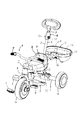
尚、本実施例では、子供用乗物を三輪車Aとして例示する。又、三輪車Aの進行方向を前後方向とし、該前後方向に対して水平面内で直交する方向を左右方向とし、同じく前後方向に対して鉛直面内で直交する方向を上下方向とする。 In the present embodiment, the vehicle for children is illustrated as a tricycle A. Further, the traveling direction of the tricycle A is the front-rear direction, the direction orthogonal to the front-rear direction in the horizontal plane is the left-right direction, and the direction orthogonal to the front-rear direction in the vertical plane is the vertical direction.
本実施例の三輪車Aは、図1〜図4に示すようなものであり、すなわち、サドルBを備えたフレームCの前端に、グリップ部Dが夫々形成された支持杆Eが左右回動可能に支持されている。該支持杆E下端には、ペダルFで回転する前輪Gが支持されている。フレームCの後端には、左右2本の後輪Hを回転可能に支持した車軸Iが支持されている。フレームCのサドルBの下方には、フットレストJがフレームCから垂設されている。フレームCのサドルBの後方には、押し手棒1が立設されている。そして、前記車軸Iの上方に荷台10が着脱可能に装備されている。
The tricycle A of this embodiment is as shown in FIGS. 1 to 4, that is, the support rod E in which the grip portion D is formed at the front end of the frame C provided with the saddle B can be rotated left and right. It is supported by. A front wheel G rotated by a pedal F is supported at the lower end of the support rod E. At the rear end of the frame C, an axle I that supports the left and right rear wheels H rotatably is supported. A footrest J is suspended from the frame C below the saddle B of the frame C.
本実施例の押し手棒1は、三輪車AのフレームCに固定される下パイプ部材2と、該下パイプ部材2に上下スライド自在に挿入される上パイプ部材3と、これら下パイプ部材2と上パイプ部材3とに係脱して、上パイプ部材2のスライド状態とスライド停止状態とに切替えるディテント機構(もどり止め機構)4を備えている。
The
上パイプ部材3は、図5〜図9及び図11に示すように、下パイプ部材2に対して凹凸係合により回動が規制されている。具体的には、下パイプ部材2の後部の内周面に前方へ突設された案内凸部21と、上パイプ部材3の後側の外周面に前方へ凹設されたスライド凹部31との凹凸係合により回動を規制するようにしてある。案内凸部21は、下パイプ部材2の上端から軸線に沿ってその一部に凹設されている。スライド凹部31は、上パイプ部材の軸線方向に沿ってその全域に亘って突設されている。すなわち、上パイプ部材3は、スライド凹部31が案内凸部21に係合することよって、下パイプ部材2に対して回動が規制されると共に、上下スライドが案内される。
As shown in FIGS. 5 to 9 and 11, the rotation of the
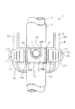
ディテント機構4は、上パイプ部材3のスライド凹部31に、その長手方向に沿って4個開孔された調節係合孔40〜43と、下パイプ部材2の案内凸部21に1個開孔され、前記調節係合孔40〜43のいずれか1個と対面する係合孔44と、対面した両係合孔に対して下パイプ部材2の外側から弾性的に、且つ前後方向に係脱する突起5と、該突起5に対して係合方向への弾性力を与えるばね部材6と、前記突起5をその軸線に沿ってばね部材6の弾性力に抗して係合解除させる操作部材7と、該操作部材7を覆うカバー部材8とから構成されている。
The
ここで、調節係合孔40〜43の位置関係を説明すると、調節係合孔40は、上パイプ部材3の最も上側に在り、上パイプ部材3が最も収縮した状態において下パイプ部材2の係合孔44と対面する。調節係合孔41は、上パイプ部材3の最も下側に在り、上パイプ部材が最も伸長した状態において下パイプ部材2の係合孔44と対面する。調節係合孔42は、調節係合孔41の上方に、調節係合孔43は、調節係合孔42の上方に、夫々一定間隔を空けて位置し、上パイプ部材3の伸縮により、調節係合孔42及び調節係合孔43を係合孔44と対面させる。そして、各調節係合孔40〜43のいずれかが係合孔44と対面したときに、対面した調節係合孔と係合孔に突起5が弾性係合することにより、上パイプ部材3が下パイプ部材2に対してスライド停止状態になる。
Here, the positional relationship between the
突起5は、係合孔44と係合する端部(以下「先端部」という)51が球面状に形成された弾丸形状を呈するものであり、他端部(以下「後端部」という)52が操作部材7に固定されている。ばね部材6は、圧縮ばねであり、突起5と下パイプ部材2を挟んで前方に位置すると共に、操作部材7と下パイプ部材2に亘り、該操作部材7に対して突起5が係合孔44に係合する方向に弾発力が作用するように装着されている。操作部材7は、下パイプ部材2に対して前後方向にスライド可能に嵌合されており、ばね部材6の弾発力により常に前方側に位置することにより、突起5の係合孔44に対する係合状態を保持し、該ばね部材6の弾発力に抗して後方へスライドすることにより、突起5を係合孔44から抜く(係合解除する)ようにしている。カバー部材8は、下パイプ部材2の上端から案内凸部21の全部が隠れる部位までを覆うように形成され、操作部材7を内側でスライド可能に支持する案内支持部81と、操作部材7をカバー部材8の外側から操作するための左右2箇所の開口部82,83を備えている。
The
以下、操作部材7の具体的な構成について説明すると、操作部材7は、下パイプ部材2にスライド可能に嵌合し、前後方向に長い長円状の嵌合孔70が形成されたスライド支持部71と、該スライド支持部71に対して左右方向に突設され、スライド支持部71を後方へ押し操作する左右2個の操作部72,73を備えている。嵌合孔70は、長手方向の径が、操作部材7が後方スライドしたときに突起5が係合孔44から抜ける程度の径であり、短手方向の径が、下パイプ部材2の径と適合する程度の径である。
Hereinafter, a specific configuration of the
スライド支持部71の後方には、突起5がその先端部51を嵌合孔70内に突出するように固定され、前方には、ばね部材6を装着する凹部74が形成されている。凹部74は後方が開口されており、この開口からばね部材6を嵌合孔70内に突出させて下パイプ部材2に接触するようにしている。
On the rear side of the
操作部72,73は、スライド支持部71から左右径方向に突出させてあり、前方に湾曲状に形成した押し面部72A,73Aを有し、該押し面部72A,73Aには、上下方向に沿う凸条72B,73Bが左右方向に3本形成されている。この凸条72B,73Bは、押し操作するときの指の滑り止め効果を有するものである。又、押し面部72A,73Aは、開口部82,83から露出しており、カバー部材8の外側から押し操作が可能になっている。
The
次に、カバー部材8における案内支持部81の操作部材7の支持形態について説明すると、案内支持部81は、操作部材7を上下方向から挟持するように、カバー部材8の内側の上下に夫々形成された上側支持部81A及び下側支持部81Bと、カバー部材8の内側周面に形成され、操作部72,73の側面部72C、73Cを側方から近接して支持する操作部案内面部81C,81Dと、スライド支持部71の前方側の左右側面部71A,71Bを側方から近接して支持するスライド支持部案内面81E,81Fとから構成されている。開口部82,83は、カバー部材8の軸線を境にして左右前方に開口されている。符号82A,83Aは、スライド支持部案内面81E,81Fに沿って、開口部82,83と連続するように形成されたスライド案内用開口部である。カバー部材8は、図11に示すように、左側部材8Aと右側部材8Bの2部材からなり、両部材を下パイプ部材2に対して左右から挟むように合体させて構成されている。
Next, the support form of the
すなわち、この案内支持部81は、上側支持部81A及び下側支持部81Bが操作部材7を上下から支持することにより、操作部材7の下パイプ部材2に対する上下動を防止し、操作部案内面部81C,81D及びスライド支持部案内面81E,81Fが操作部7を左右から支持することにより、操作部材7の下パイプ部材2に対する回動を防止する。したがって、操作部72,73のいずれを押し操作しても、案内支持部81を真っ直ぐ後方へスライドさせることができ、又、押し操作をしている指を操作部72,73から離せば、ばね部材6の弾発力で前方へスライド可能な状態となる。
That is, the
本実施例の押し手棒1によれば、操作部材7の押し操作中では、常に、突起5が係合解除状態に保持されるため、上パイプ部材3のスライドを伸縮上限から伸縮下限に亘って連続的に行うことができる。すなわち、上パイプ部材3を目的の位置までスライドさせるときに、従来のように段階的な突起の係脱を行なうことなくスライドさせることができる。又、左右2箇所の操作部72,73のいずれを押し操作しても、突起5の係合を行えるので、使用者の右手側及び左手側のいずれの指でも押し操作することができる。又、操作部72,73が前方に位置しているので、押し手棒1の後側から突起5の係合解除操作を行うことができ、例えば、押し手棒1を操作して三輪車Aを押し動かしている途中で、押し手棒1の長さを変更したい場合には、三輪車Aを止め、そのままの状態で操作部72,73の押し操作を行うことができる。
According to the
尚、本考案における調節係合孔の数は、本実施例で例示した4個に限るものではなく、4個未満及び5個以上としてもよく、少なくとも、上パイプ部材のスライド上限位置とスライド下限位置にあればよい(図示せず)。又、本考案における操作部の操作方向及び数は、本実施例で例示した左右2個に限るものではなく、操作方向については後方から押し操作する形態でもよいし、数は1個でもよい(図示せず)。操作部を1個とした場合、下パイプ部材の前方又は後方が好ましい(図示せず)。 The number of adjustment engagement holes in the present invention is not limited to four illustrated in the present embodiment, and may be less than four or five or more. At least the upper slide position and the lower slide limit of the upper pipe member It only needs to be in position (not shown). In addition, the operation direction and the number of operation units in the present invention are not limited to the two left and right illustrated in the present embodiment, and the operation direction may be a push operation from the rear, or the number may be one ( Not shown). When the number of operation portions is one, the front or rear of the lower pipe member is preferable (not shown).
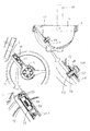
以下、図12〜図14に基づいて、荷台10の取り付け構造について説明すると、荷台10は、取手11を有するバケツ状に形成されたものであり、該荷台10が三輪車AのフレームCに対し、連結部材9を介して着脱自在に取り付けられている。取手11は、荷台10に対して傾倒自在に支持されており、取付け状態においては、荷台10の開口部12の周囲に沿うように倒し、取外して持ち運ぶときには立てることができるようにしてある。
Hereinafter, the mounting structure of the
連結部材9は、車軸Iを支持する左右2本のフレームC間に架設状に設けられた支持板90に開孔された貫通孔9Aと、荷台10の前部壁面10Aに貫通状に設けられ、貫通孔9Aに対して抜き挿し自在とし、挿し込むことで三輪車Aに対して荷台10を連結する連結杆9Bとを備えている。
The connecting member 9 is provided in a penetrating manner in a through
貫通孔9Aは、左右方向を長手方向とする長方形として形成されている。連結杆9Bは、軸心を中心として回動するように支持され、荷台10内に突出する端部(以下「後端部」という)91に、連結杆9Bを回動操作する操作体92が固定されている。又、貫通孔9A側の端部(以下「先端部」という)93には、前記貫通孔9Aを通過すると共に、連結杆9Aの回動により支持板90の貫通孔9A周りに掛止される掛止体94が固着されている。
The through-
操作体92は、円形状に形成され、連結杆9Bに固定される回動板92Aと、該回動板92Aの中心線に突設された回動つまみ92Bとから構成され、該回動つまみ92Bを指でつまんで回動板92Aを回動させることにより連結杆9Bが回動する。
The operating
掛止体94は、貫通孔9Aよりも一回り小さい相似形とする板状に形成されている。すなわち、貫通孔9Aに連結杆9Bを貫通(挿入及び抜き取り)させるときには、掛止体94の長手側を貫通孔の長手側に沿わせた状態(図14(b)参照)とし、貫通させた掛止体94を掛止状態(抜け止め状態)にするには、操作体92を回動操作して掛止体94の長手方向を貫通孔9Aの長手方向と交差(図14(a)参照、図示では90度)させた状態としている。
The retaining
支持板90の前方側には、貫通孔9Aと連通し、貫通した掛止体94を収容する収容凹部95が凹設されている。収容凹部95は貫通した掛止体94が突出しない程度の深さを有するものである。又、収容凹部95は、蓋部96により塞がれており、この蓋部96により、砂利等が収容凹部95に入ってしまうことによる連結部材9の操作に対する影響を防いでいる。
On the front side of the
前部壁面10Aには、掛合部94が掛合状態のときに、回動板92Aの裏面に接触してその回動に抵抗を与える抵抗突起97が突設されている。すなわち、抵抗突起97が回動板92Aの回動に抵抗を与えることで、三輪車Aを動かしているときの振動等による掛止体94の回動を防止し、三輪車Aを動かしているときに突然荷台10が外れてしまうことを防止している。
The
本実施例の荷台10の取り付け構造によれば、回動つまみ92Aを回動させるという操作で、荷台10を三輪車Aから取外すことができると共に、貫通孔9Aに対する掛止体94に貫通後、回動つまみ92Aを回動させるという操作で、荷台10を三輪車Aに対して連結できる。すなわち、回動つまみ92Aの回動という簡単な操作で荷台10の着脱が行えるため、三輪車Aに乗る程度の子供でも簡単に荷台10の着脱ができる。又、荷台10を取外すことにより、この荷台10による遊びを行なうことができる。更に、荷台10に備えられた取手により、荷台10の持ち運びも容易に行うことができる。又、連結杆を有した他の荷台に交換することも容易にできる。
According to the mounting structure of the
尚、本考案における連結杆は、本実施例で例示した荷台側に設けた形態に限るものではなく、フレーム側に設けてもよく、この場合、回動つまみがフレーム側にあり、貫通孔が荷台に開孔される(図示せず)。又、本考案における貫通孔及び掛止体の形状は、本実施例で例示した長方形に限るものではなく、例えば、楕円形や長円形、あるいは、三角形等のように、掛止体の回動により該掛止体が貫通孔周りに掛止される形状であればよい(図示せず)。又、本考案における掛止体の形状は、本実施例で例示したように、貫通孔と相似形とした形態に限るものではなく、貫通孔に対して貫通可能で、且つ掛止体の回動により該掛止体が貫通孔周りに掛止される形状であればよい(図示せず)。 The connecting rod in the present invention is not limited to the form provided on the cargo bed side exemplified in this embodiment, and may be provided on the frame side. In this case, the rotation knob is on the frame side, and the through hole is provided. A hole is opened in the loading platform (not shown). In addition, the shape of the through hole and the latching body in the present invention is not limited to the rectangle illustrated in the present embodiment, and for example, the rotation of the latching body such as an ellipse, an oval, or a triangle is possible. Therefore, the shape of the latching body is not limited as long as the latching body is latched around the through hole. Further, the shape of the latching body in the present invention is not limited to the shape similar to the through hole as exemplified in the present embodiment, and the latching body can be penetrated through the through hole and the latch body can be rotated. Any shape may be used as long as the latching body is latched around the through hole by movement (not shown).
本考案は、例示した実施の形態に限定するものではなく、実用新案登録請求の範囲に記載された内容から逸脱することなく、他の構成による実施も可能である。 The present invention is not limited to the illustrated embodiment, and can be implemented in other configurations without departing from the contents described in the claims of the utility model registration.
A:三輪車
C:フレーム
1:押し手棒
2:下パイプ部材
3:上パイプ部材
4:ディテント機構
40:調節係合孔
41:調節係合孔
42:調節係合孔
43:調節係合孔
44:係合孔
5:突起
6:ばね部材
7:操作部材
71:スライド支持部
72:操作部
73:操作部
8:カバー部材
82:開口部
83:開口部
A: Tricycle C: Frame 1: Pusher bar 2: Lower pipe member 3: Upper pipe member 4: Detent mechanism 40: Adjustment engagement hole 41: Adjustment engagement hole 42: Adjustment engagement hole 43: Adjustment engagement hole 44 : Engagement hole 5: Projection 6: Spring member 7: Operation member 71: Slide support part 72: Operation part 73: Operation part 8: Cover member 82: Opening part 83: Opening part
Claims (6)
前記ディテント機構は、前記上パイプ部材に軸線方向に沿って複数個開孔された調節係合孔と、
前記下パイプ部材に開孔され、前記調節係合孔と対面する係合孔と、
前記両係合孔に対して下パイプ部材の外側から弾性的に係脱する突起と、
前記突起に対して係合方向への弾性力を与えるばね部材と、
前記突起をその軸線に沿って前記弾性部材の弾性力に抗して係合解除させる操作部材と、を備えていることを特徴とする子供用乗物の押手棒の伸縮装置。 A lower pipe member fixed to the rear part of the child vehicle, an upper pipe member inserted into the lower pipe member so as to be slidable up and down, and the lower pipe member and the upper pipe member are engaged with and disengaged from each other. In a telescopic device for a push rod of a children's vehicle provided with a detent mechanism for switching between a state and a slide stop state,
The detent mechanism includes a plurality of adjustment engagement holes that are opened in the axial direction in the upper pipe member;
An engagement hole opened in the lower pipe member and facing the adjustment engagement hole;
A protrusion that elastically engages and disengages from the outside of the lower pipe member with respect to both the engagement holes;
A spring member for applying an elastic force in the engaging direction to the protrusion;
An operation member for releasing a push bar of a children's vehicle, comprising: an operation member that disengages the protrusion along an axis thereof against an elastic force of the elastic member.
Priority Applications (1)
| Application Number | Priority Date | Filing Date | Title |
|---|---|---|---|
| JP2008001433U JP3141910U (en) | 2008-03-12 | 2008-03-12 | Telescopic device for push rod of children's vehicle |
Applications Claiming Priority (1)
| Application Number | Priority Date | Filing Date | Title |
|---|---|---|---|
| JP2008001433U JP3141910U (en) | 2008-03-12 | 2008-03-12 | Telescopic device for push rod of children's vehicle |
Publications (1)
| Publication Number | Publication Date |
|---|---|
| JP3141910U true JP3141910U (en) | 2008-05-22 |
Family
ID=43291946
Family Applications (1)
| Application Number | Title | Priority Date | Filing Date |
|---|---|---|---|
| JP2008001433U Expired - Fee Related JP3141910U (en) | 2008-03-12 | 2008-03-12 | Telescopic device for push rod of children's vehicle |
Country Status (1)
| Country | Link |
|---|---|
| JP (1) | JP3141910U (en) |
Cited By (1)
| Publication number | Priority date | Publication date | Assignee | Title |
|---|---|---|---|---|
| JP2015526345A (en) * | 2012-09-03 | 2015-09-10 | ガリレオ トライクス エルティディ | Free-wheeling, free-steering, foldable multi-stage tricycle with single-action release mechanism |
-
2008
- 2008-03-12 JP JP2008001433U patent/JP3141910U/en not_active Expired - Fee Related
Cited By (1)
| Publication number | Priority date | Publication date | Assignee | Title |
|---|---|---|---|---|
| JP2015526345A (en) * | 2012-09-03 | 2015-09-10 | ガリレオ トライクス エルティディ | Free-wheeling, free-steering, foldable multi-stage tricycle with single-action release mechanism |
Similar Documents
| Publication | Publication Date | Title |
|---|---|---|
| EP3280633B1 (en) | Collapsible rolling walker | |
| JP2018534091A (en) | Folding kickboard | |
| US8313115B2 (en) | Stroller | |
| KR20020064183A (en) | Folding stroller | |
| JP4616915B2 (en) | Brake braking structure | |
| GB2318099A (en) | Folding mechanism for a pushchair | |
| JP5100930B2 (en) | stroller | |
| JP2009035014A (en) | Lock mechanism of caster | |
| JP5913546B2 (en) | stroller | |
| JP5755344B2 (en) | Folding baby carriage | |
| JP2000233756A (en) | Baby carriage | |
| JP3141910U (en) | Telescopic device for push rod of children's vehicle | |
| JP3141911U (en) | Child vehicle loading platform mounting structure | |
| JP5736060B2 (en) | stroller | |
| JP5832466B2 (en) | Wheelbarrow | |
| KR101973459B1 (en) | Brake mechanism for baby carriage, wheel holding mechanism for baby carriage, and baby carriage | |
| US20060103114A1 (en) | Structure for swiveling and anchoring the front wheel of a tricycle | |
| KR101078992B1 (en) | Children's tricycle having a foldable foot supporter | |
| WO2011087506A1 (en) | Stroller basket | |
| JP3840657B2 (en) | Child riding equipment for bicycles | |
| JP6081223B2 (en) | Vehicle console box | |
| JP6837889B2 (en) | Brake mechanism for pedestrian vehicles | |
| JP3132359U (en) | Shopping wheelbarrow | |
| JP3117365U (en) | Manual doll toy | |
| JP2009090777A (en) | Mounting vehicle for bicycle |
Legal Events
| Date | Code | Title | Description |
|---|---|---|---|
| R150 | Certificate of patent (=grant) or registration of utility model |
Free format text: JAPANESE INTERMEDIATE CODE: R150 |
|
| FPAY | Renewal fee payment (prs date is renewal date of database) |
Free format text: PAYMENT UNTIL: 20110430 Year of fee payment: 3 |
|
| FPAY | Renewal fee payment (prs date is renewal date of database) |
Free format text: PAYMENT UNTIL: 20130430 Year of fee payment: 5 |
|
| FPAY | Renewal fee payment (prs date is renewal date of database) |
Free format text: PAYMENT UNTIL: 20130430 Year of fee payment: 5 |
|
| FPAY | Renewal fee payment (prs date is renewal date of database) |
Free format text: PAYMENT UNTIL: 20140430 Year of fee payment: 6 |
|
| R250 | Receipt of annual fees |
Free format text: JAPANESE INTERMEDIATE CODE: R250 |
|
| LAPS | Cancellation because of no payment of annual fees |