【0001】
【考案の属する技術分野】
本考案は、積雪道路や凍結道路における車椅子の移動に用いられるそりに関する。
【0002】
【従来の技術】
積雪路おける車椅子の移動をスムース、かつ安全に行うために、従来では、車椅子にそりを取り付けたものが提案されている。
たとえば、そりを車椅子に対して車輪の接地面よりも高い位置にして着脱可能に取り付けて、冬場の積雪路ではそりを取り付けた状態で使用し、冬場以外の通常路ではそりを取り外して使用する車椅子がある。(特許文献1参照)
また、そりを車椅子の後輪部位に上下動可能に取り付けて、冬場の積雪路または凍結路での使用では、そりを後輪接地面よりも低い位置まで下降させて後輪を積雪面または凍結面から離間させ、冬場以外の通常路では、そりを後輪接地面よりも高い位置まで上昇させて後輪を路面に接地させて使用する車椅子がある。(特許文献2参照)
【0003】
【特許文献1】
実用新案登録第3087885号公報(〔0005〕、〔図1〕)
【特許文献2】
特開2000−232996号公報(〔0006〕、〔図1〕、〔図2〕)
【0004】
しかしながら、特許文献1の車椅子では、積雪が少ない場合においては、そりが積雪面から離間して、積雪面に車輪のみが接地することになるので、そりの効果を発揮できない状況が発生する。
特許文献2の車椅子では、そり使用時においては後輪が積雪面や凍結面から離間するので、積雪が少ない場合においてもそりの効果を発揮することができるものの、前輪がそのまま積雪面や凍結面上に接地しているので、たとえば、車椅子の前進時において前輪が積雪によって埋まったり、凍結面によって滑ったりして、車椅子の操作が行い難くなるということが発生する。
【0005】
【考案が解決しようとする課題】
そこで本考案は、積雪や凍結の状況にかかわらず、車椅子の操作を確実、かつ容易に行うとともに、積雪路および凍結路と通常路における使用切り替えを容易、かつ迅速に行うことを課題とし、この課題を解決する車椅子用そりの提供を目的とする。
【0006】
【課題を解決するための手段】
上記目的を達成するために本考案は下記の技術的手段を採用する。
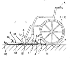
その技術的手段は、図1に示すように、車椅子Aにおけるすべての車輪1の接地面2を載置する載置面3を備え、この載置面3には、車椅子Aの通常の前後動操作によって載置面3に対して車椅子を載せたり降ろしたりするアプローチ部4が連設されている車椅子用そりBである。(請求項1)
【0007】
本考案によれば、車椅子用そり(以下、「そり」と略称する。)Bを積雪面または凍結面に置き、車椅子Aをアプローチ部4から前進させることにより、すべての車輪1の接地面2が載置面3に載置された状態で、車椅子AがそりB上にセットされる。
つまり、そりBが積雪面上または凍結面上に接触し、車椅子Aの車輪1のすべてがそりB上に有るので、この状態でそりBを前進させれば、何ら抵抗無く容易に車椅子Aの操作を行うことができる。
そして、載置された状態から車椅子Aを後退させることによって、車椅子AをそりBから簡単、かつ迅速に脱出させることができる。
【0008】
【考案の実施の形態】
本考案のそりBは、そりBの進行中に車椅子Aの落下を防止するために、車輪1の載置面3からの脱落を阻止する構成を備えている。(請求項2)
脱落を阻止する構成として、たとえば、図示するように、載置面3の左右縁部に壁面31を立設する構成が例示できる。
【0009】
本考案のそりBは、車椅子Aを押すことによってそりBの進行を行う形態、そりBを押してそりの進行を行う形態が含まれる。
車椅子Aを押すことによってそりBの進行を行う形態の場合、そりB上での前輪10および後輪11の少なくとも一方の前方回転を阻止(請求項3)して、車椅子Aの押し力をそりに伝達することが例示できる。
前輪10の前方回転を阻止する構成としては、たとえば、図示するように、そりBのトップ部B3に前輪10を接触させることによってその前方回転を阻止する構成が例示できる。
【0010】
また、車椅子Aの前輪10は、左右方向に回動するため、そりBの進行中に車椅子Aが不安定になる可能性が有るため、そりBの進行時に、前輪10の回動を阻止する(請求項4)ことが好適である。
前輪10の左右回動を阻止する構成としては、たとえば、図示するように、載置面3に前輪10の左右を挟持して回動を防止する挟持部6を備える構成が例示できる。
【0011】
さらに、車椅子AをそりBへ載せたり降ろしたりするときに、そりBがずれないように定位置に保持するために、図に示すように、そりの進行を阻止するストッパー部7を備える(請求項5)ことが好適である。
そして、車椅子Aの横幅に対応および仕舞性の向上のために、図示するように、左側の車輪1を載置する載置面3と右側の車輪1を載置する載置面3とが左右に離間近接可能とする(請求項6)ことが好適である。
【0012】
【実施例】
以下、本考案の実施例を図面に基づいて説明する。
本考案のそりBは、左そりB1と右そりB2を左右一対とするものであり、左そりB1と右そりB2とは、伸縮可能な連結管5によって一体化してある。
連結管5は、前後2ヶ所あり、共に左そりB1と右そりのB2側部にそれぞれ固定したスライド管51と、左右のスライド管51が嵌合固定される固定管52とから構成してある。
スライド管51は、固定管52の外周面からボルト53を貫通ねじ込みし、貫通したボルト53の先端の接触圧によって固定管52に固定され、ボルト53を緩めることによって固定管52に対してスライドするようにしてある。
【0013】
左そりB1と右そりB2のそれぞれには、そりBの進行中に車椅子Aの落下を防止するために、載置面3の左右縁部に壁面31を立設してあり、壁面31が立設されないテール部を車椅子Aのアプローチ部4としている。
【0014】
本実施例のそりBは、車椅子Aを押すことによってそりBの進行を行う形態のものであり、そりBのトップ部B3に前輪10を接触させることによってその前方回転を阻止して、車椅子Aに対する押し力をそりBに伝達して進行させるようにしている。
そして、アプローチ部4から車椅子AをそりB上に載せて前進させ、前輪10が前記トップ部B3に接触してそれ以上の前進が止められる。
【0015】
また、本実施例のそりBには、載置面3に車椅子Aの前輪10の左右を挟持して前輪10の回動を防止する挟持部6を備えている。
挟持部6は、そりBのトップ部B3から載置面3の前輪部分に亘り長手方向に沿って、前輪10の左右に位置する凸条部61を突設し、さらに凸条部61の後端側を左右に拡開して前輪10を左右の凸状部61間へ導くように構成してある。
左右の凸状部61の間隔は、前輪10の幅よりもやや幅広とし、前輪10を抵抗無く進入させ、しかも前輪10の左右回動を防止できる間隔である。
【0016】
さらに、本実施例のそりBには、車椅子AをそりBへ載せたり降ろしたりするときに、そりBがずれないように定位置に保持するためのストッパー部7を備えている。
ストッパー部7は、前記後側の連結管5における固定管52に前後方向回動可能に軸支してあり、前方へ回動させることによってそりBの保持状態を解除し、後方へ回動させることによってそりBが保持状態となるようにしている。
【0017】
ストッパー部7の構成は、ストッパー本体71と支持軸72からなり、支持軸72の先端にストッパー本体71が固定され、支持軸72の後端を前記固定管52に前後方向回動可能に軸支してなる。
保持解除状態では、ストッパー本体71が積雪面または凍結面から離間している状態となる位置において、支持軸72が固定管52に接触してそれ以上の回動が阻止される。(図1参照)
ストッパー本体71は、略熊手状を呈する形態のものであり、保持状態において先端の凹凸部が積雪面または凍結面に突き刺さることでそりの進行を阻止し(図3参照)、保持解除状態において先端の凹凸部が積雪面または凍結面から離間してそりBを進行可能とする。
【0018】
なお、本考案は、例示した実施例における構造に限定されるものではなく、実用新案登録請求の範囲の各項に記載の範囲において、他の構造にすることも任意である。
【図面の簡単な説明】
【図1】本考案に係る車椅子用そりの断面図。
【図2】同、平面図。
【図3】保持状態を示す側面図。
【図4】左そりと右そりを離間させた状態の平面図。
【符号の説明】
A:車椅子
B:車椅子用そり
1:車輪
2:接地面
3:載置面
4:アプローチ部
31:壁面
B1:左そり
B2:右そり
B3:トップ部
10:前輪
5:連結管
6:挟持部
7:ストッパー部[0001]
[Technical field to which the invention belongs]
The present invention relates to a sled used for moving a wheelchair on a snowy road or a frozen road.
[0002]
[Prior art]
In order to smoothly and safely move a wheelchair on a snowy road, a wheelchair with a sled has been conventionally proposed.
For example, the sled is mounted on the wheelchair higher than the ground contact surface of the wheel and removably attached.Use the sled mounted on snowy roads in winter and remove the sled on normal roads other than winter. There is a wheelchair. (See Patent Document 1)
In addition, the sled is attached to the rear wheel part of the wheelchair so that it can move up and down, and when used on snowy roads or frozen roads in winter, the sled is lowered to a position lower than the ground contact surface of the rear wheel, and the rear wheel is placed on the snowy or frozen surface. There is a wheelchair that is separated from a surface and used on a normal road other than in winter by raising the sled to a position higher than the rear wheel grounding surface to ground the rear wheel to the road surface. (See Patent Document 2)
[0003]
[Patent Document 1]
Japanese Utility Model Registration No. 3087885 ([0005], [FIG. 1])
[Patent Document 2]
JP-A-2000-232996 ([0006], [FIG. 1], [FIG. 2])
[0004]
However, in the wheelchair of Patent Literature 1, when the amount of snow is small, the sled is separated from the snow-covered surface, and only the wheels are in contact with the snow-covered surface.
In the wheelchair of Patent Literature 2, when the sled is used, the rear wheel is separated from the snow-covered surface or the frozen surface. Therefore, even when the snow is small, the effect of the sled can be exhibited, but the front wheel is directly used as the snow-covered surface or the frozen surface. Since the front wheel is grounded, for example, when the wheelchair moves forward, the front wheel is buried by snow or slips on a frozen surface, which makes it difficult to operate the wheelchair.
[0005]
[Problems to be solved by the invention]
In view of the above, the present invention has been made to make it possible to operate the wheelchair reliably and easily irrespective of the state of snow and freezing, and to easily and quickly switch between use on snowy roads and frozen roads and normal roads. An object of the present invention is to provide a wheelchair sled that solves the problem.
[0006]
[Means for Solving the Problems]
In order to achieve the above object, the present invention employs the following technical means.
As shown in FIG. 1, the technical means includes a mounting surface 3 on which the grounding surfaces 2 of all the wheels 1 in the wheelchair A are mounted. This is a wheelchair sled B in which an approach portion 4 for mounting and dismounting a wheelchair on a mounting surface 3 by operation is continuously provided. (Claim 1)
[0007]
According to the present invention, a wheelchair sled (hereinafter referred to as a sled) B is placed on a snow-covered surface or a frozen surface, and the wheelchair A is advanced from the approach portion 4 so that the ground contact surface 2 of all the wheels 1 is formed. The wheelchair A is set on the sled B in a state where is mounted on the mounting surface 3.
That is, since the sled B contacts the snow-covered surface or the frozen surface and all the wheels 1 of the wheelchair A are on the sled B, if the sled B is advanced in this state, the wheelchair A can be easily moved without any resistance. Operations can be performed.
By retracting the wheelchair A from the mounted state, the wheelchair A can be easily and quickly escaped from the sled B.
[0008]
[Embodiment of the invention]
The sled B of the present invention has a structure for preventing the wheelchair A from falling off from the mounting surface 3 in order to prevent the wheelchair A from falling while the sled B is in progress. (Claim 2)
As a configuration for preventing dropping, for example, a configuration in which wall surfaces 31 are erected on the left and right edges of the mounting surface 3 as illustrated can be exemplified.
[0009]
The sled B of the present invention includes a form in which the sled B is advanced by pushing the wheelchair A, and a form in which the sled B is advanced by pushing the sled B.
In the case where the sled B is advanced by pushing the wheelchair A, the forward rotation of at least one of the front wheel 10 and the rear wheel 11 on the sled B is prevented (claim 3), and the pushing force of the wheelchair A is reduced. Can be exemplified.
As a configuration for preventing the front wheel 10 from rotating forward, for example, as shown in the drawing, a configuration for preventing the front wheel 10 from rotating forward by bringing the front wheel 10 into contact with a top portion B3 of the sled B can be exemplified.
[0010]
In addition, since the front wheel 10 of the wheelchair A rotates in the left-right direction, the wheelchair A may become unstable while the sled B is in progress. (Claim 4) is preferable.
As a configuration for preventing the left and right rotation of the front wheel 10, for example, as shown in the drawing, a configuration including a holding portion 6 for holding the left and right of the front wheel 10 on the mounting surface 3 to prevent the rotation can be exemplified.
[0011]
Further, in order to hold the sled B at a fixed position so that the sled B does not shift when the wheelchair A is put on or lowered from the sled B, as shown in the figure, a stopper portion 7 for preventing the sled from moving is provided. Item 5) is preferable.
As shown in the figure, the mounting surface 3 on which the left wheel 1 is mounted and the mounting surface 3 on which the right wheel 1 are mounted are left and right in order to cope with the width of the wheelchair A and to improve the finish. (Claim 6) is preferable.
[0012]
【Example】
Hereinafter, embodiments of the present invention will be described with reference to the drawings.
The sled B of the present invention has a left sled B1 and a right sled B2 as a pair of left and right, and the left sled B1 and the right sled B2 are integrated by an extendable connecting pipe 5.
The connecting pipes 5 are provided at two front and rear positions, each of which comprises a slide pipe 51 fixed to the left warp B1 and a right warp B2 side, respectively, and a fixed pipe 52 to which the left and right slide pipes 51 are fitted and fixed. .
The slide tube 51 is screwed with a bolt 53 from the outer peripheral surface of the fixed tube 52, is fixed to the fixed tube 52 by the contact pressure of the tip of the penetrated bolt 53, and slides on the fixed tube 52 by loosening the bolt 53. It is like that.
[0013]
In each of the left sled B1 and the right sled B2, wall surfaces 31 are erected on the left and right edges of the mounting surface 3 to prevent the wheelchair A from falling while the sled B is in progress. The tail portion not provided is the approach portion 4 of the wheelchair A.
[0014]
The sled B of this embodiment is of a form in which the sled B advances by pushing the wheelchair A, and the front wheel 10 is brought into contact with the top portion B3 of the sled B to prevent the forward rotation of the sled B. Is transmitted to the sled B and is advanced.
Then, the wheelchair A is put on the sled B from the approach portion 4 and moved forward, and the front wheel 10 comes into contact with the top portion B3 to stop further movement.
[0015]
Further, the sled B of the present embodiment is provided with a holding portion 6 for holding the left and right sides of the front wheel 10 of the wheelchair A on the mounting surface 3 to prevent the rotation of the front wheel 10.
The holding portion 6 protrudes from the top portion B3 of the sled B to the front wheel portion of the mounting surface 3 along the longitudinal direction, and protrudes the protruding portions 61 located on the left and right of the front wheel 10. The end side is expanded left and right to guide the front wheel 10 between the left and right convex portions 61.
The interval between the left and right convex portions 61 is set to be slightly wider than the width of the front wheel 10 so as to allow the front wheel 10 to enter without resistance and to prevent the left and right rotation of the front wheel 10.
[0016]
Further, the sled B of the present embodiment is provided with a stopper portion 7 for holding the sled B at a fixed position so that the sled B does not shift when the wheelchair A is put on or lowered from the sled B.
The stopper portion 7 is pivotally supported on the fixed tube 52 of the rear connection tube 5 so as to be able to rotate in the front-rear direction. By rotating the stopper portion 7 forward, the holding state of the sled B is released, and the stopper portion 7 is rotated rearward. This allows the sled B to be in the holding state.
[0017]
The stopper portion 7 includes a stopper main body 71 and a support shaft 72, the stopper main body 71 is fixed to the tip of the support shaft 72, and the rear end of the support shaft 72 is pivotally supported by the fixed pipe 52 so as to be able to rotate in the front-rear direction. Do it.
In the holding release state, at a position where the stopper main body 71 is separated from the snow-covered surface or the frozen surface, the support shaft 72 comes into contact with the fixed pipe 52 and further rotation is prevented. (See Fig. 1)
The stopper main body 71 has a substantially rake-like form. In the holding state, the uneven portion at the tip pierces the snow-covered or frozen surface to prevent the sled from advancing (see FIG. 3). Makes the sled B move forward by separating from the snow-covered or frozen surface.
[0018]
Note that the present invention is not limited to the structure in the illustrated embodiment, and it is optional to use another structure within the scope described in each section of the utility model registration claims.
[Brief description of the drawings]
FIG. 1 is a sectional view of a wheelchair sled according to the present invention.
FIG. 2 is a plan view of the same.
FIG. 3 is a side view showing a holding state.
FIG. 4 is a plan view showing a state in which a left sled is separated from a right sled.
[Explanation of symbols]
A: Wheelchair B: Wheelchair sled 1: Wheel 2: Ground contact surface 3: Placement surface 4: Approach part 31: Wall surface B1: Left sled B2: Right sled B3: Top part 10: Front wheel 5: Connecting pipe 6: Clamping part 7: Stopper part