JP2025521663A - DEVICE WITH THERMALLY ANISOTROPIC CONDUCTIVE CHANNEL AND THERMAL INSULATING MATERIAL - Patent application - Google Patents
DEVICE WITH THERMALLY ANISOTROPIC CONDUCTIVE CHANNEL AND THERMAL INSULATING MATERIAL - Patent application Download PDFInfo
- Publication number
- JP2025521663A JP2025521663A JP2024576514A JP2024576514A JP2025521663A JP 2025521663 A JP2025521663 A JP 2025521663A JP 2024576514 A JP2024576514 A JP 2024576514A JP 2024576514 A JP2024576514 A JP 2024576514A JP 2025521663 A JP2025521663 A JP 2025521663A
- Authority
- JP
- Japan
- Prior art keywords
- segmented
- thermally
- thermally conductive
- anisotropic conductive
- channels
- Prior art date
- Legal status (The legal status is an assumption and is not a legal conclusion. Google has not performed a legal analysis and makes no representation as to the accuracy of the status listed.)
- Pending
Links
Images
Classifications
-
- H10W40/25—
-
- H—ELECTRICITY
- H05—ELECTRIC TECHNIQUES NOT OTHERWISE PROVIDED FOR
- H05K—PRINTED CIRCUITS; CASINGS OR CONSTRUCTIONAL DETAILS OF ELECTRIC APPARATUS; MANUFACTURE OF ASSEMBLAGES OF ELECTRICAL COMPONENTS
- H05K7/00—Constructional details common to different types of electric apparatus
- H05K7/20—Modifications to facilitate cooling, ventilating, or heating
- H05K7/2039—Modifications to facilitate cooling, ventilating, or heating characterised by the heat transfer by conduction from the heat generating element to a dissipating body
- H05K7/20436—Inner thermal coupling elements in heat dissipating housings, e.g. protrusions or depressions integrally formed in the housing
- H05K7/20445—Inner thermal coupling elements in heat dissipating housings, e.g. protrusions or depressions integrally formed in the housing the coupling element being an additional piece, e.g. thermal standoff
- H05K7/20472—Sheet interfaces
- H05K7/20481—Sheet interfaces characterised by the material composition exhibiting specific thermal properties
-
- H10W40/257—
Landscapes
- Engineering & Computer Science (AREA)
- Physics & Mathematics (AREA)
- Microelectronics & Electronic Packaging (AREA)
- Thermal Sciences (AREA)
- Cooling Or The Like Of Semiconductors Or Solid State Devices (AREA)
- Chemical & Material Sciences (AREA)
- Materials Engineering (AREA)
- Condensed Matter Physics & Semiconductors (AREA)
- General Physics & Mathematics (AREA)
- Computer Hardware Design (AREA)
- Power Engineering (AREA)
- Cooling Or The Like Of Electrical Apparatus (AREA)
Abstract
熱を発生するように構成された構成要素を含む領域と、この領域に結合された熱伝導層であって、複数のセグメント化された熱異方性伝導チャネルを含む、熱伝導層と、を備える、デバイス。複数のセグメント化された熱異方性伝導チャネルからの各セグメント化された熱異方性伝導チャネルは、第1の方向に整列している。複数のセグメント化された熱異方性伝導チャネルからの各セグメント化された熱異方性伝導チャネルは、第1の方向に熱伝達能力を提供するように構成されている。熱伝導層は、(i)構成要素の接合温度を低下させ、かつ/又は(ii)デバイスの表面温度を低下させるように構成されている。
A device comprising: a region including components configured to generate heat; and a thermally conductive layer coupled to the region, the thermally conductive layer including a plurality of segmented thermally anisotropic conductive channels, each segmented thermally anisotropic conductive channel from the plurality of segmented thermally anisotropic conductive channels aligned in a first direction, each segmented thermally anisotropic conductive channel from the plurality of segmented thermally anisotropic conductive channels configured to provide a heat transfer capability in the first direction, the thermally conductive layer configured to (i) reduce a junction temperature of the components and/or (ii) reduce a surface temperature of the device.
Description
様々な特徴は、放熱構成要素を含むデバイスに関する。 Various features relate to devices that include heat dissipation components.
電子デバイスは、集積デバイスなど、熱を発生する多くの構成要素を含む。集積デバイスは、過熱する傾向がある可能性があり、これにより、集積デバイス及び電子デバイスの他の構成要素の性能に影響を及ぼす可能性がある。過熱している集積デバイスは、高い接合温度を有し、その結果、電子デバイスの表面温度が高くなる可能性がある。これにより、最終的に、電子デバイスの性能に影響を及ぼす可能性がある。熱を発生する構成要素を含む電子デバイスの放熱性能を改善することが継続的に必要とされている。例えば、熱を発生する構成要素の接合温度を低下させること、及び/又は熱を発生する構成要素を含む電子デバイスの表面温度を低下させることが継続的に必要とされている。 Electronic devices include many components, such as integrated devices, that generate heat. The integrated devices may be prone to overheating, which may affect the performance of the integrated devices and other components of the electronic device. Integrated devices that are overheating may have high junction temperatures, which may result in high surface temperatures of the electronic device, which may ultimately affect the performance of the electronic device. There is a continuing need to improve the heat dissipation performance of electronic devices that include heat-generating components. For example, there is a continuing need to reduce the junction temperatures of heat-generating components and/or reduce the surface temperatures of electronic devices that include heat-generating components.
様々な特徴は、放熱デバイスを含むデバイスに関する。 Various features relate to devices that include heat dissipation devices.
一実施例は、熱を発生するように構成された構成要素を含む領域と、この領域に結合された熱伝導層とを備えるデバイスを提供し、熱伝導層は、複数のセグメント化された熱異方性伝導チャネルを含む。 One embodiment provides a device comprising a region including a component configured to generate heat and a thermally conductive layer coupled to the region, the thermally conductive layer including a plurality of segmented thermally anisotropic conductive channels.
別の実施例は、熱を発生するように構成された第1の集積デバイスと、熱を発生するように構成された第2の集積デバイスとを含む領域を備えるデバイスを提供する。デバイスは、この領域に結合されたセグメント化された異方性熱伝達の手段を備える。 Another embodiment provides a device comprising a region including a first integrated device configured to generate heat and a second integrated device configured to generate heat. The device comprises a means for segmented anisotropic heat transfer coupled to the region.
以下に記載される「発明を実施するための形態」を、同様の参照符号が全体を通して対応するものを識別する図面と併せ読むことにより、様々な特徴、性質、及び利点が明らかとなり得る。 Various features, properties, and advantages may become apparent from reading the detailed description set forth below in conjunction with the drawings in which like reference characters identify correspondingly throughout.
以下の説明では、本開示の様々な態様の完全な理解をもたらすために、具体的な詳細が記載される。しかしながら、当業者には、これらの具体的な詳細を伴わずとも、諸態様を実践することができる点が理解されるであろう。例えば、不必要な詳細で諸態様を不明瞭にすることを回避するために、回路がブロック図で示される場合がある。他の事例では、本開示の諸態様を不明瞭にすることがないように、周知の回路、構造、及び技術が、詳細には示されない場合がある。 In the following description, specific details are set forth to provide a thorough understanding of various aspects of the present disclosure. However, one of ordinary skill in the art will understand that aspects may be practiced without these specific details. For example, circuits may be shown in block diagrams to avoid obscuring aspects in unnecessary detail. In other instances, well-known circuits, structures, and techniques may not be shown in detail so as not to obscure aspects of the present disclosure.
本開示は、熱を発生するように構成された構成要素を含む領域と、この領域に結合された熱伝導層とを備えるデバイス(例えば、電子デバイス)を説明し、熱伝導層は、複数のセグメント化された熱異方性伝導チャネルを含む。複数のセグメント化された熱異方性伝導チャネルからの各セグメント化された熱異方性伝導チャネルは、第1の方向に整列している。複数のセグメント化された熱異方性伝導チャネルからの各セグメント化された熱異方性伝導チャネルは、第1の方向に高い熱伝導率を有し、別の方向に低い熱伝導率を有する。例えば、複数のセグメント化された熱異方性伝導チャネルからの各セグメント化された熱異方性伝導チャネルは、まず(例えば、最初に)主に第1の方向に熱伝達を提供するように構成されている。熱伝導層は、グラファイト(例えば、グラファイトシート)を含んでもよい。熱伝導層は、局所的な指向性熱伝達を提供して、デバイス内の構成要素間の熱分離を可能にするように構成されている。例えば、以下で更に説明するように、この領域は、第1の集積デバイス及び第2の集積デバイスを含むことができ、熱伝導層は、1つの集積デバイスによって生成された熱が他の集積デバイスに向かって放散しない(又は最小限に放散する)ように、熱伝達を提供し、かつ/又は熱を放散するように構成することができる。以下で更に説明するように、複数の熱異方性伝導チャネルの使用は、集積デバイス接合温度及びデバイス表面温度を低下させるのに役立つ。 The present disclosure describes a device (e.g., an electronic device) comprising a region including components configured to generate heat and a thermally conductive layer coupled to the region, the thermally conductive layer including a plurality of segmented thermally anisotropic conductive channels. Each segmented thermally anisotropic conductive channel from the plurality of segmented thermally anisotropic conductive channels is aligned in a first direction. Each segmented thermally anisotropic conductive channel from the plurality of segmented thermally anisotropic conductive channels has a high thermal conductivity in the first direction and a low thermal conductivity in another direction. For example, each segmented thermally anisotropic conductive channel from the plurality of segmented thermally anisotropic conductive channels is configured to primarily (e.g., initially) provide heat transfer in a first direction. The thermally conductive layer may include graphite (e.g., a graphite sheet). The thermally conductive layer is configured to provide localized directional heat transfer to enable thermal isolation between components within the device. For example, as described further below, the region can include a first integrated device and a second integrated device, and the thermally conductive layer can be configured to provide heat transfer and/or dissipate heat such that heat generated by one integrated device does not dissipate (or dissipates minimally) toward the other integrated device. As described further below, the use of multiple thermally anisotropic conductive channels helps to reduce integrated device junction temperatures and device surface temperatures.
熱伝導チャネルを有する層を備える例示的なデバイス
図1及び図2は、熱伝導チャネルを備える少なくとも1つの熱伝導層を含むことができるデバイス100を示す。デバイス100は、携帯電話(例えば、スマートフォン)などの電子デバイスを含むことができる。図1は、ディスプレイ102及びケーシング本体104を含むデバイス100の例示的な正面図を示す。図2は、デバイス100の例示的な背面図を示す。デバイス100は、集積デバイス205と、集積デバイス215と、カメラ220と、を含む。集積デバイス205は、第1の集積デバイスとすることができる。集積デバイス215は、第2の集積デバイスとすることができる。集積デバイス205及び第2の集積デバイス215は、デバイス100の内部に配置されている。例えば、集積デバイス205及び集積デバイス215は、ケーシング本体104の内部に配置されている。カメラ220は、デバイス100のケーシング本体104に少なくとも部分的に埋め込まれていてもよい。
1 and 2 show a device 100 that can include at least one thermally conductive layer with a thermally conductive channel. The device 100 can include an electronic device such as a mobile phone (e.g., a smartphone). FIG. 1 shows an exemplary front view of the device 100 including a display 102 and a casing body 104. FIG. 2 shows an exemplary rear view of the device 100. The device 100 includes an integrated device 205, an integrated device 215, and a camera 220. The integrated device 205 can be a first integrated device. The integrated device 215 can be a second integrated device. The integrated device 205 and the second integrated device 215 are disposed inside the device 100. For example, the integrated device 205 and the integrated device 215 are disposed inside the casing body 104. The camera 220 can be at least partially embedded in the casing body 104 of the device 100.
以下で更に説明するように、デバイス100は、熱伝導チャネルを備える少なくとも1つの熱伝導層を含むことができる。熱伝導チャネルは、(i)第1の方向(例えば、長さ)に沿って高い熱伝導率を提供し、かつ(ii)別の方向(例えば、幅)に沿って低い熱伝導率を提供するように構成された、熱異方性伝導チャネルであってもよい。例えば、熱伝導チャネルは、(i)最初に主に(例えば、実質的に、ほとんど、ほぼ完全に)熱伝導チャネルの長さに沿って熱伝達を提供し、かつ(ii)最初に他の方向(例えば、第2の方向、第3の方向、幅)に沿って熱伝達をほとんど又は全く提供しないように構成された、熱異方性伝導チャネルであってもよい。この構成は、集積デバイス205によって生成された熱が最初に集積デバイス215に向かって放散しないこと、及び/又は集積デバイス215によって生成された熱が集積デバイス205に向かって放散しないことを確実にするのに役立つことができる。したがって、熱を発生するように構成された1つ又は複数の構成要素からの効果的かつ効率的な放熱を依然として提供しながら、デバイス100内の構成要素(例えば、集積デバイス)間の熱分離を可能にするために局所的な指向性熱伝達を提供するように、層(例えば、熱伝導層、熱伝達層)を構成することができる。 As further described below, the device 100 may include at least one thermally conductive layer comprising a thermally conductive channel. The thermally conductive channel may be a thermally anisotropic conductive channel configured to (i) provide high thermal conductivity along a first direction (e.g., length) and (ii) provide low thermal conductivity along another direction (e.g., width). For example, the thermally conductive channel may be a thermally anisotropic conductive channel configured to (i) provide heat transfer primarily (e.g., substantially, mostly, nearly completely) along the length of the thermally conductive channel and (ii) provide little or no heat transfer primarily along the other direction (e.g., second direction, third direction, width). This configuration may help ensure that heat generated by the integrated device 205 does not dissipate toward the integrated device 215 initially and/or that heat generated by the integrated device 215 does not dissipate toward the integrated device 205 initially. Thus, layers (e.g., thermally conductive layers, heat transfer layers) can be configured to provide localized, directional heat transfer to enable thermal isolation between components (e.g., integrated devices) within device 100 while still providing effective and efficient heat dissipation from one or more components configured to generate heat.
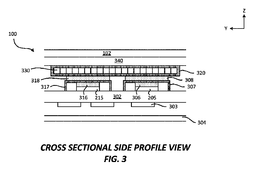
図3は、図2のデバイス100の断面AAの例示的な断面プロファイル図を示す。デバイス100は、ディスプレイ102、バックカバー304、基板302、複数の構成要素303、集積デバイス205、集積デバイス215、熱界面材料306、熱界面材料316、シールド307、シールド317、熱界面材料308、熱界面材料318、熱伝達構成要素320、熱伝導層330、及びディスプレイモジュール340を含む。バックカバー304は、デバイス100のケーシング本体104の一部であってもよい。 3 shows an exemplary cross-sectional profile view of cross section AA of device 100 of FIG. 2. Device 100 includes display 102, back cover 304, substrate 302, multiple components 303, integrated device 205, integrated device 215, thermal interface material 306, thermal interface material 316, shield 307, shield 317, thermal interface material 308, thermal interface material 318, heat transfer component 320, thermal conduction layer 330, and display module 340. Back cover 304 may be part of casing body 104 of device 100.
熱伝導層330は、(i)第1の方向(例えば、長さ)に沿って高い熱伝導率を提供し、かつ(ii)別の方向(例えば、幅、第2の方向)に沿って低い熱伝導率を提供するように構成された、熱異方性伝導チャネルを含む。熱伝導層の実施例については、少なくとも図5~図12において以下で更に説明する。 Thermally conductive layer 330 includes thermally anisotropic conductive channels configured to provide (i) high thermal conductivity along a first direction (e.g., length) and (ii) low thermal conductivity along another direction (e.g., width, second direction). Examples of thermally conductive layers are further described below in at least Figures 5-12.
基板302は、プリント回路基板(printed circuit board、PCB)であってもよい。複数の構成要素303は、基板302の背面に結合することができる。複数の構成要素303は、デバイス100のバックカバー304に面することができる。集積デバイス205及び/又は集積デバイス215は、複数のはんだ相互接続部(図示せず)を介して、基板302の前面に結合することができる。熱界面材料306は、集積デバイス205の背面に結合することができる。シールド307は、基板302に結合することができ、集積デバイス205を取り囲んでもよい。シールド307は、熱界面材料306を介して集積デバイス205に結合することができる。熱界面材料316は、集積デバイス215の背面に結合することができる。シールド317は、基板302に結合することができ、集積デバイス215を取り囲んでもよい。シールド317は、熱界面材料316を介して集積デバイス215に結合することができる。シールド307及び/又はシールド317は、導電性材料(例えば、金属、銅)を含んでもよく、電磁干渉(electromagnetic interference、EMI)シールドとして動作するように構成することができる。シールド307及び/又はシールド317は、接地に結合されるように構成することができる。 The substrate 302 may be a printed circuit board (PCB). The components 303 may be coupled to a rear surface of the substrate 302. The components 303 may face a back cover 304 of the device 100. The integrated device 205 and/or the integrated device 215 may be coupled to a front surface of the substrate 302 via a number of solder interconnects (not shown). A thermal interface material 306 may be coupled to a rear surface of the integrated device 205. A shield 307 may be coupled to the substrate 302 and may surround the integrated device 205. The shield 307 may be coupled to the integrated device 205 via the thermal interface material 306. A thermal interface material 316 may be coupled to a rear surface of the integrated device 215. The shield 317 may be coupled to the substrate 302 and may surround the integrated device 215. The shield 317 may be coupled to the integrated device 215 via the thermal interface material 316. Shield 307 and/or shield 317 may include a conductive material (e.g., metal, copper) and may be configured to act as an electromagnetic interference (EMI) shield. Shield 307 and/or shield 317 may be configured to be coupled to ground.
熱界面材料308は、シールド307に結合されている。熱界面材料318は、シールド317に結合されている。熱界面材料308及び熱界面材料318は、熱伝達構成要素320に結合されている。熱伝導層330は、熱伝達構成要素320の内部に配置することができる。熱伝導層330は、1つ又は複数の熱伝導層を含むことができる。いくつかの実装形態では、熱伝導層330は、熱伝達構成要素320によって部分的に覆われていてもよい。例えば、熱伝導層330の一方の側は、熱伝達構成要素320に結合され、熱伝導層330の他方の側は、熱界面材料308及び/又は熱界面材料318に直接結合されている。熱伝達構成要素320は、異なる形状及び/又はサイズを有してもよい。例えば、熱伝達構成要素320は、熱伝導層330のためのケース及び/又はプレートであるように構成することができる。熱伝達構成要素320は、ディスプレイモジュール340に結合されている。ディスプレイモジュール340は、ディスプレイ102と接触していてもよく、又は接触していなくてもよい。熱伝達構成要素320は、デバイス内での熱伝導層330の取り扱い及び配置を助けることができる。いくつかの実装形態では、熱伝達構成要素320は、任意選択であってもよい。そのような事例では、熱伝導層330は、ディスプレイモジュール340、熱界面材料308、及び/又は熱界面材料318に直接結合することができる(例えば、直接接触することができる)。 The thermal interface material 308 is coupled to the shield 307. The thermal interface material 318 is coupled to the shield 317. The thermal interface material 308 and the thermal interface material 318 are coupled to the heat transfer component 320. The thermally conductive layer 330 can be disposed inside the heat transfer component 320. The thermally conductive layer 330 can include one or more thermally conductive layers. In some implementations, the thermally conductive layer 330 can be partially covered by the heat transfer component 320. For example, one side of the thermally conductive layer 330 is coupled to the heat transfer component 320, and the other side of the thermally conductive layer 330 is directly coupled to the thermal interface material 308 and/or the thermal interface material 318. The heat transfer component 320 may have different shapes and/or sizes. For example, the heat transfer component 320 can be configured to be a case and/or a plate for the thermally conductive layer 330. The heat transfer component 320 is coupled to the display module 340. The display module 340 may or may not be in contact with the display 102. The heat transfer component 320 may aid in handling and positioning of the thermally conductive layer 330 within the device. In some implementations, the heat transfer component 320 may be optional. In such cases, the thermally conductive layer 330 may be directly bonded to (e.g., in direct contact with) the display module 340, the thermal interface material 308, and/or the thermal interface material 318.
図3は、熱を発生させるように構成された少なくとも1つの構成要素を含む領域を含むデバイス100の一実施例を示し、熱伝導層は、熱を発生させるように構成された少なくとも1つの構成要素を含む領域に(例えば、直接的又は間接的に)結合されている。熱を発生するように構成された構成要素を含むデバイス100の領域は、集積デバイス205(例えば、第1の集積デバイス)及び/又は集積デバイス215(例えば、第2の集積デバイス)を含むことができる。したがって、集積デバイス205及び/又は集積デバイス215は、熱を発生するように構成することができる構成要素の例である。いくつかの実装形態では、熱伝導層330は、熱を発生させるように構成された少なくとも1つの構成要素を含む領域内にあると見なすことができる。異なる実装形態は、デバイス100の領域を異なるように定義することができる。デバイス100の領域は、デバイス100の内部領域を含んでもよい。デバイス100の領域に結合された熱伝導層(例えば、330)は、熱伝導層が、デバイス100の領域内の1つ若しくは複数の構成要素及び/又は1つ若しくは複数の部分に結合されている(例えば、直接結合されている、間接的に結合されている、機械的に結合されている)ことを意味することができる。以下で更に詳細に説明するように、熱伝導層330は、熱異方性伝導チャネルの使用により、集積デバイス205と集積デバイス215(及び場合によっては他の構成要素)との間の熱分離を可能にするために、局所的な指向性熱伝達を提供するように構成することができる。熱伝導層330は、異なる形状、サイズ、構成及び/又は配置を有してもよい。一実施例では、熱伝導層330は、約0.8ミリメートルの厚さを有することができる。一実施例では、熱伝達構成要素320は、約1ミリメートルの総厚を有することができる。しかしながら、熱伝達構成要素320は、他の厚さを有してもよい。以下の図5~図12は、デバイス100内の熱伝導層330として、及び/又は熱伝導層330とともに実装することができる、熱伝導層の構成の異なる実施例を図示及び説明する。熱伝導層330は、セグメント化された異方性熱伝達の手段であってもよい。 3 illustrates an example of device 100 including a region including at least one component configured to generate heat, where a thermally conductive layer is coupled (e.g., directly or indirectly) to the region including at least one component configured to generate heat. The region of device 100 including a component configured to generate heat may include integrated device 205 (e.g., a first integrated device) and/or integrated device 215 (e.g., a second integrated device). Thus, integrated device 205 and/or integrated device 215 are examples of components that may be configured to generate heat. In some implementations, thermally conductive layer 330 may be considered to be within the region including at least one component configured to generate heat. Different implementations may define the region of device 100 differently. The region of device 100 may include an interior region of device 100. A thermally conductive layer (e.g., 330) coupled to a region of the device 100 can mean that the thermally conductive layer is coupled (e.g., directly coupled, indirectly coupled, mechanically coupled) to one or more components and/or one or more portions within the region of the device 100. As described in more detail below, the thermally conductive layer 330 can be configured to provide localized directional heat transfer to enable thermal isolation between the integrated device 205 and the integrated device 215 (and possibly other components) through the use of thermally anisotropic conduction channels. The thermally conductive layer 330 may have different shapes, sizes, configurations, and/or arrangements. In one example, the thermally conductive layer 330 can have a thickness of about 0.8 millimeters. In one example, the thermally conductive component 320 can have a total thickness of about 1 millimeter. However, the thermally conductive component 320 may have other thicknesses. Figures 5-12 below illustrate and describe different examples of thermally conductive layer configurations that can be implemented as and/or with the thermally conductive layer 330 in the device 100. The thermally conductive layer 330 may be a means of segmented anisotropic heat transfer.
図3に示す構成及び/又は配置は、例示的なものであることに留意されたい。いくつかの実装形態では、他の構成要素が存在してもよく、構成要素のうちのいくつかは、デバイス100内に異なって配置されていてもよく、及び/又は構成要素のうちのいくつかは、任意選択であってもよい。 It should be noted that the configuration and/or arrangement shown in FIG. 3 is exemplary. In some implementations, other components may be present, some of the components may be arranged differently within device 100, and/or some of the components may be optional.
本開示では、多数の座標系(X-Y-Z、X’-Y’-Z’、X’’-Y’’-Z’’)が使用され、説明されることに留意されたい。これらの例示的な座標系は、熱伝導層及び/又はセグメント化された熱伝導チャネルの異方性熱特性を説明するのを助けるために使用される。これらの異なる座標系は、互いに独立していてもよく、又は1つ若しくは複数の座標系に関連していてもよい。他の座標系が、向き及び/又は整列を図示するために使用されてもよい。 It should be noted that multiple coordinate systems (X-Y-Z, X'-Y'-Z', X"-Y"-Z") are used and described in this disclosure. These example coordinate systems are used to help describe the anisotropic thermal properties of the thermally conductive layer and/or segmented thermally conductive channels. These different coordinate systems may be independent of one another or may be related to one or more other coordinate systems. Other coordinate systems may be used to illustrate orientation and/or alignment.
集積デバイス(例えば、205、215)は、ダイ(例えば、半導体ベアダイ)を含むことができる。集積デバイスは、電力管理集積回路(power management integrated circuit、PMIC)を含み得る。集積デバイスは、アプリケーションプロセッサを含み得る。集積デバイスは、モデムを含み得る。集積デバイスは、無線周波数(radio frequency、RF)デバイス、受動デバイス、フィルタ、キャパシタ、インダクタ、アンテナ、送信機、受信機、ガリウムヒ素(GaAs)ベースの集積デバイス、表面弾性波(surface acoustic wave、SAW)フィルタ、バルク弾性波(bulk acoustic wave、BAW)フィルタ、発光ダイオード(light emitting diode、LED)集積デバイス、シリコン(Si)ベースの集積デバイス、炭化ケイ素(SiC)ベースの集積デバイス、メモリ、電源管理プロセッサ、及び/又はこれらの組み合わせを含み得る。集積デバイス(例えば、205、215)は、少なくとも1つの電子回路(例えば、第1の電子回路、第2の電子回路など)を含むことができる。集積デバイスは、トランジスタを含み得る。集積デバイスは、電気構成要素及び/又は電気デバイスの一例であり得る。いくつかの実装形態では、集積デバイスはチップレットであり得る。チップレットは、他のタイプの集積デバイスに対して使用される製造プロセスと比較して、より良好な歩留まりをもたらす1つ又は複数の製造プロセスを使用して製造することができ、これにより、チップレットを製造する全体的なコストを引き下げることができる。異なるチップレットは、異なるサイズ及び/又は形状を有し得る。異なるチップレットは、異なる機能を提供するように構成することができる。異なるチップレットは、異なる相互接続部密度(例えば、異なる幅及び/又は間隔を有する相互接続部)を有し得る。いくつかの実装形態では、いくつかのチップレットを使用して、1つ又は複数のチップ(例えば、1つ又は複数の集積デバイス)の機能を実行することができる。いくつかの機能を実行する、いくつかのチップレットを使用することは、パッケージの機能の全てを実行するために単一のチップを使用することに比べて、パッケージの全体的なコストを低減し得る。 The integrated device (e.g., 205, 215) may include a die (e.g., a semiconductor bare die). The integrated device may include a power management integrated circuit (PMIC). The integrated device may include an application processor. The integrated device may include a modem. The integrated device may include radio frequency (RF) devices, passive devices, filters, capacitors, inductors, antennas, transmitters, receivers, gallium arsenide (GaAs)-based integrated devices, surface acoustic wave (SAW) filters, bulk acoustic wave (BAW) filters, light emitting diode (LED) integrated devices, silicon (Si)-based integrated devices, silicon carbide (SiC)-based integrated devices, memories, power management processors, and/or combinations thereof. The integrated device (e.g., 205, 215) may include at least one electronic circuit (e.g., a first electronic circuit, a second electronic circuit, etc.). The integrated device may include a transistor. The integrated device may be an example of an electrical component and/or an electrical device. In some implementations, the integrated device may be a chiplet. The chiplet may be manufactured using one or more manufacturing processes that provide better yields compared to manufacturing processes used for other types of integrated devices, thereby lowering the overall cost of manufacturing the chiplet. Different chiplets may have different sizes and/or shapes. Different chiplets may be configured to provide different functions. Different chiplets may have different interconnect densities (e.g., interconnects with different widths and/or spacings). In some implementations, several chiplets may be used to perform the functions of one or more chips (e.g., one or more integrated devices). Using several chiplets that perform several functions may reduce the overall cost of the package compared to using a single chip to perform all of the functions of the package.
集積デバイスのうちの1つ又は複数は、無線周波数(RF)パッケージ内に実装することができる。RFパッケージは、無線周波数フロントエンド(radio frequency front end、RFFE)パッケージとすることができる。パッケージは、ワイヤレスフィデリティ(Wireless Fidelity、WiFi)通信及び/又はセルラ通信(例えば、2G、3G、4G、5G)を提供するように構成することができる。パッケージは、グローバルシステムフォーモバイル(Global System for Mobile、GSM)通信、ユニバーサル移動通信システム(Universal Mobile Telecommunications System、UMTS)、及び/又はロングタームエボリューション(Long-Term Evolution、LTE)をサポートするように構成することができる。パッケージは、異なる周波数及び/又は異なる通信プロトコルを有する信号を送受信するように構成することができる。 One or more of the integrated devices may be implemented in a radio frequency (RF) package. The RF package may be a radio frequency front end (RFFE) package. The package may be configured to provide Wireless Fidelity (WiFi) communications and/or cellular communications (e.g., 2G, 3G, 4G, 5G). The package may be configured to support Global System for Mobile (GSM) communications, Universal Mobile Telecommunications System (UMTS), and/or Long-Term Evolution (LTE). The packages can be configured to transmit and receive signals having different frequencies and/or different communication protocols.
図4は、熱伝導シート400の例示的な図を示す。熱伝導シート400は、平面に沿って熱異方性伝導性であってもよい。熱伝導シート400は、主に平面(例えば、X’-Y’平面)に沿って高い熱伝達能力を提供する(例えば、熱を放散する)ように構成されている。したがって、熱は、平面(例えば、X’-Y’)の任意の方向に沿って良好に放散することができる。しかしながら、熱伝導シート400は、他の方向及び/又は他の平面において、熱伝達能力が低い、ほとんどない(平面に沿った熱伝達と比較して相対的に)、又は全くない。例えば、熱伝導シート400は、Z’方向、X’-Z’平面のZ’方向、及び/又はY’-Z’平面のZ’方向において、熱伝達能力をほとんど又は全く提供しない。熱伝導シート400は、グラファイト(例えば、グラファイトシート)を含んでもよい。いくつかの実装形態では、X’-Y’平面内の熱伝導シート400は、約1000~1900ワット毎メートルケルビン(W/(mk))の範囲内の熱伝導率を有する。したがって、平面(例えば、X’-Y’)の任意の方向に沿って、熱伝導シート400は、約1000~1900ワット毎メートルケルビン(W/(mk))の範囲内の熱伝導率を有する。いくつかの実装形態では、Z’方向の熱伝導シート400は、30ワット毎メートルケルビン(W/(mk))未満(例えば、3.5W/(mk))の熱伝導率を有する。 FIG. 4 shows an exemplary diagram of a thermally conductive sheet 400. The thermally conductive sheet 400 may be thermally anisotropically conductive along a plane. The thermally conductive sheet 400 is configured to provide high heat transfer capability (e.g., dissipate heat) primarily along a plane (e.g., the X'-Y' plane). Thus, heat can be well dissipated along any direction of the plane (e.g., the X'-Y'). However, the thermally conductive sheet 400 has low, little (relatively compared to heat transfer along a plane), or no heat transfer capability in other directions and/or other planes. For example, the thermally conductive sheet 400 provides little or no heat transfer capability in the Z' direction, the Z' direction in the X'-Z' plane, and/or the Z' direction in the Y'-Z' plane. The thermally conductive sheet 400 may include graphite (e.g., a graphite sheet). In some implementations, the thermally conductive sheet 400 in the X'-Y' plane has a thermal conductivity in the range of about 1000 to 1900 Watts per meter Kelvin (W/(mk)). Thus, along any direction in the plane (e.g., X'-Y'), the thermally conductive sheet 400 has a thermal conductivity in the range of about 1000 to 1900 Watts per meter Kelvin (W/(mk)). In some implementations, the thermally conductive sheet 400 in the Z' direction has a thermal conductivity of less than 30 Watts per meter Kelvin (W/(mk)) (e.g., 3.5 W/(mk)).
図5は、熱伝導層500の例示的な図を示す。熱伝導層500は、平面上の方向に沿って熱異方性伝導性であってもよい。熱伝導層500は、複数のセグメント化された熱伝導チャネル502(例えば、セグメント化された熱異方性伝導チャネル)を含む。熱伝導層500は、主に平面(例えば、Y’-Z’平面)内の方向(例えば、Y’方向)に沿って熱伝達を提供する(例えば、熱を放散する)ように構成されている。したがって、熱は、平面(例えば、Y’-Z’)のY’方向に沿って良好に放散することができる。しかしながら、熱伝導シート400は、他の方向及び/又は他の平面において、(最も多くの熱伝達を提供することができる方向に対して)熱伝達能力をほとんど提供しない、又は全く提供しない場合がある。例えば、熱伝導層500は、Z’方向に熱伝達能力をほとんど又は全く提供しなくてもよい(例えば、セグメント化された熱伝導チャネル502間の熱伝達をほとんど又は全く提供しなくてもよい)。熱伝導層500は、グラファイト(例えば、グラファイトシート)を含むことができる。いくつかの実装形態では、Y’-Z’平面のY’方向の熱伝導層500は、約1000~1900ワット毎メートルケルビン(W/(mk))の範囲内の熱伝導率を有する。いくつかの実装形態では、Z’方向の熱伝導層500は、30ワット毎メートルケルビン(W/(mk))未満(例えば、3.5W/(mk))の熱伝導率を有する。セグメント化された熱伝導チャネル(例えば、502)は、第1の方向に高い熱伝導率値を有するが、少なくとも第2の方向に低い熱伝導率値を有する、熱伝導材料を含むことができる。例えば、少なくとも1つのセグメント化された熱伝導チャネルは、セグメント化された熱伝導チャネルの長さに沿って高い熱伝導率値を有するが、近隣のセグメント化された熱伝導チャネルに向かって低い熱伝導率値を有する、熱伝導材料を含む。セグメント化された熱伝導チャネルは、第1の方向に比較的高い熱伝導率値を有するが、少なくとも第2の方向に比較的低い熱伝導率値を有する、熱伝導材料を含む。セグメント化された熱伝導チャネルは、第1の方向に(例えば、チャネルの長さに沿って)比較的高い熱伝導率値を有するが、少なくとも第2の方向に(例えば、1つ又は複数のチャネル(単数又は複数)の幅に沿って)比較的低い熱伝導率値を有する。したがって、熱伝導層500は、(i)第1の方向(例えば、長さ)に沿って高い熱伝導率を提供し、かつ(ii)別の方向(例えば、幅、第2の方向)に沿って低い熱伝導率を提供するように構成された、セグメント化された熱異方性伝導チャネル(例えば、502)を含む。 5 shows an exemplary diagram of a thermally conductive layer 500. The thermally conductive layer 500 may be thermally anisotropically conductive along a direction on a plane. The thermally conductive layer 500 includes a plurality of segmented thermally conductive channels 502 (e.g., segmented thermally anisotropically conductive channels). The thermally conductive layer 500 is configured to provide heat transfer (e.g., dissipate heat) primarily along a direction (e.g., Y' direction) in a plane (e.g., Y'-Z' plane). Thus, heat can be well dissipated along the Y' direction of the plane (e.g., Y'-Z'). However, the thermally conductive sheet 400 may provide little or no heat transfer capability (relative to the direction that can provide the most heat transfer) in other directions and/or planes. For example, the thermally conductive layer 500 may provide little or no heat transfer capability in the Z' direction (e.g., little or no heat transfer between the segmented thermally conductive channels 502). The thermally conductive layer 500 can include graphite (e.g., a graphite sheet). In some implementations, the thermally conductive layer 500 in the Y'-direction of the Y'-Z' plane has a thermal conductivity in the range of about 1000 to 1900 Watts per meter Kelvin (W/(mk)). In some implementations, the thermally conductive layer 500 in the Z'-direction has a thermal conductivity of less than 30 Watts per meter Kelvin (W/(mk)) (e.g., 3.5 W/(mk)). The segmented thermally conductive channels (e.g., 502) can include a thermally conductive material having a high thermal conductivity value in a first direction but a low thermal conductivity value in at least a second direction. For example, at least one segmented thermally conductive channel includes a thermally conductive material having a high thermal conductivity value along the length of the segmented thermally conductive channel but a low thermal conductivity value toward a neighboring segmented thermally conductive channel. The segmented thermally conductive channel includes a thermally conductive material having a relatively high thermal conductivity value in a first direction, but a relatively low thermal conductivity value in at least a second direction. The segmented thermally conductive channel includes a relatively high thermal conductivity value in a first direction (e.g., along the length of the channel), but a relatively low thermal conductivity value in at least a second direction (e.g., along the width of one or more channel(s). Thus, the thermally conductive layer 500 includes segmented thermally anisotropic conductive channels (e.g., 502) configured to (i) provide high thermal conductivity along a first direction (e.g., length), and (ii) provide low thermal conductivity along another direction (e.g., width, second direction).
「高い熱伝導率値」という用語は、別の熱伝導率値に対して絶対的に及び/又は相対的に高くてもよい。「低い熱伝導率値」という用語は、別の熱伝導率値に対して絶対的に及び/又は相対的に低くてもよい。本開示で使用されるとき、「比較的高い熱伝導率値」という用語は、「比較的低い熱伝導率値」の熱伝導率値よりも少なくとも5倍高い熱伝導率値を意味することができる。例えば、比較的高い熱伝導率値は、比較的低い熱伝導率値よりも少なくとも5倍高い熱伝導率値を有することができる。別の例では、比較的高い熱伝導率値は、比較的低い熱伝導率値よりも少なくとも10倍高い熱伝導率値を有することができる。更に別の例では、比較的高い熱伝導率値は、比較的低い熱伝導率値よりも少なくとも100倍高い熱伝導率値を有することができる。したがって、第1の方向の熱伝導率値(例えば、高い熱伝導率値)は、第2の方向の熱伝導率値(例えば、比較的低い熱伝導率値)よりも少なくとも5倍高い(例えば、少なくとも10倍高い、少なくとも100倍高い)熱伝導率値を有することができる。本開示において言及及び説明される熱伝導率値の範囲は、例示的なものであることに留意されたい。異なる材料は、本開示において言及及び説明される熱伝導率値よりも高い及び/又は低い値等の異なる熱伝導率値を有することができる。 The term "high thermal conductivity value" may be absolutely and/or relatively high relative to another thermal conductivity value. The term "low thermal conductivity value" may be absolutely and/or relatively low relative to another thermal conductivity value. As used in this disclosure, the term "relatively high thermal conductivity value" may mean a thermal conductivity value that is at least 5 times higher than the thermal conductivity value of a "relatively low thermal conductivity value". For example, a relatively high thermal conductivity value may have a thermal conductivity value that is at least 5 times higher than a relatively low thermal conductivity value. In another example, a relatively high thermal conductivity value may have a thermal conductivity value that is at least 10 times higher than a relatively low thermal conductivity value. In yet another example, a relatively high thermal conductivity value may have a thermal conductivity value that is at least 100 times higher than a relatively low thermal conductivity value. Thus, a thermal conductivity value in a first direction (e.g., a high thermal conductivity value) may have a thermal conductivity value that is at least 5 times higher (e.g., at least 10 times higher, at least 100 times higher) than a thermal conductivity value in a second direction (e.g., a relatively low thermal conductivity value). It should be noted that the ranges of thermal conductivity values mentioned and described in this disclosure are exemplary. Different materials can have different thermal conductivity values, such as values higher and/or lower than the thermal conductivity values mentioned and described in this disclosure.
複数のセグメント化された熱伝導チャネル502は、第1のセグメント化された熱伝導チャネル502aと、第2のセグメント化された熱伝導チャネル502bと、第3のセグメント化された熱伝導チャネル502cと、第4のセグメント化された熱伝導チャネル502dとを含む。 The plurality of segmented heat conduction channels 502 includes a first segmented heat conduction channel 502a, a second segmented heat conduction channel 502b, a third segmented heat conduction channel 502c, and a fourth segmented heat conduction channel 502d.
図5に示すように、複数のセグメント化された熱伝導チャネル502からの各セグメント化された熱伝導チャネルは、平面(例えば、Y’-Z’平面)に沿って第1の方向(例えば、Y’方向)に整列している。例えば、複数のセグメント化された熱伝導チャネル502からの各セグメント化された熱伝導チャネルの長さは、平面(例えば、Y’-Z’平面)に沿って第1の方向(例えば、Y’方向)に整列している。更に、複数のセグメント化された熱伝導チャネル502からの各セグメント化された熱伝導チャネル(例えば、502a、502b、502c、502d)は、主に第1の平面(例えば、Y’-Z’平面)の第1の方向(例えば、セグメント化された熱伝導チャネルの長さに沿ったY’方向)に熱伝達を提供するように構成された熱異方性伝導チャネルを含む。複数のセグメント化された熱伝導チャネル502は、少なくとも1つの接着剤503を介して結合されている。少なくとも1つの接着剤503は、糊及び/又は結合剤を含んでもよい。少なくとも1つの接着剤503は、接着剤503a、接着剤503b、接着剤503c、及び接着剤503dを含むことができる。少なくとも1つの接着剤503は、セグメント化された熱伝導チャネル(例えば、502a、502b、502c、502d)の間に配置されていてもよい。例えば、接着剤503aは、第1のセグメント化された熱伝導チャネル502aと第2のセグメント化された熱伝導チャネル502bとの間に配置することができる。接着剤503bは、第2のセグメント化された熱伝導チャネル502bと第3のセグメント化された熱伝導チャネル502cとの間に配置することができる。接着剤503cは、第3のセグメント化された熱伝導チャネル502cと第4のセグメント化された熱伝導チャネル502dとの間に配置することができる。接着剤は、必ずしも、セグメント化された熱伝導チャネル間に、及び/又はセグメント化された熱伝導チャネルの全長に沿って存在しなくてもよいことに留意されたい。セグメント化された熱伝導チャネルの各々は、切断されたグラファイトシートによって画定されてもよい。 As shown in FIG. 5, each segmented heat conduction channel from the plurality of segmented heat conduction channels 502 is aligned in a first direction (e.g., Y' direction) along a plane (e.g., Y'-Z' plane). For example, the length of each segmented heat conduction channel from the plurality of segmented heat conduction channels 502 is aligned in a first direction (e.g., Y' direction) along a plane (e.g., Y'-Z' plane). Furthermore, each segmented heat conduction channel (e.g., 502a, 502b, 502c, 502d) from the plurality of segmented heat conduction channels 502 includes a thermal anisotropic conduction channel configured to provide heat transfer primarily in a first direction (e.g., Y' direction along the length of the segmented heat conduction channel) of the first plane (e.g., Y'-Z' plane). The plurality of segmented heat conduction channels 502 are bonded via at least one adhesive 503. The at least one adhesive 503 may include a glue and/or a bonding agent. The at least one adhesive 503 may include adhesive 503a, adhesive 503b, adhesive 503c, and adhesive 503d. The at least one adhesive 503 may be disposed between the segmented thermal conduction channels (e.g., 502a, 502b, 502c, 502d). For example, adhesive 503a may be disposed between the first segmented thermal conduction channel 502a and the second segmented thermal conduction channel 502b. Adhesive 503b may be disposed between the second segmented thermal conduction channel 502b and the third segmented thermal conduction channel 502c. Adhesive 503c may be disposed between the third segmented thermal conduction channel 502c and the fourth segmented thermal conduction channel 502d. It should be noted that adhesives may not necessarily be present between the segmented thermal conduction channels and/or along the entire length of the segmented thermal conduction channels. Each of the segmented thermal conduction channels may be defined by a cut graphite sheet.
いくつかの実装形態では、Y’-Z’平面のY’方向の各セグメント化された熱伝導チャネル(例えば、502a、502b、502c、502d)は、約1000~1900ワット毎メートルケルビン(W/(mk))の範囲内の熱伝導率を有する。いくつかの実装形態では、Z’方向、X’-Z’平面のZ’方向、及び/又はY’-Z’平面のZ’方向の各セグメント化された熱伝導チャネル(例えば、502a、502b、502c、502d)は、30ワット毎メートルケルビン(W/(mk))未満(例えば、3.5W/(mk))の熱伝導率を有する。各セグメント化された熱伝導チャネルは、熱異方性伝導チャネル(例えば、第1の熱異方性伝導チャネル、第2の熱異方性伝導チャネル、第3の熱異方性伝導チャネル、第4の熱異方性伝導チャネル)であってもよい。各セグメント化された熱伝導チャネルは、セグメント化された熱伝導チャネルの長さに沿って高い熱伝導率(例えば、高い熱伝導率値、比較的高い熱伝導率値、第1の方向の熱伝導率、第1の方向の熱伝導率値)を有することができる。各セグメント化された熱伝導チャネルは、セグメント化された熱伝導チャネルの幅に沿って低い熱伝導率(例えば、低い熱伝導率値、比較的低い熱伝導率値、第2の方向の熱伝導率、第2の方向の熱伝導率値)を有することができる。各セグメント化された熱伝導チャネルは、隣接する及び/又は近隣のセグメント化された熱伝導チャネル間で低い熱伝導率(例えば、低い熱伝導率値、比較的低い熱伝導率値、第2の方向の熱伝導率、第2の方向の熱伝導率値)を有することができる。したがって、隣接する及び/又は近隣の熱伝導チャネル(例えば、第1の熱伝導チャネルと第2の熱伝導チャネル)間の熱伝導率値は、低くてもよく、かつ/又は熱伝導チャネルの長さに沿った熱伝導チャネルの熱伝導率値より低くてもよい。 In some implementations, each segmented thermal conduction channel (e.g., 502a, 502b, 502c, 502d) in the Y' direction of the Y'-Z' plane has a thermal conductivity in the range of about 1000 to 1900 Watts per meter Kelvin (W/(mk)). In some implementations, each segmented thermal conduction channel (e.g., 502a, 502b, 502c, 502d) in the Z' direction, the Z' direction of the X'-Z' plane, and/or the Z' direction of the Y'-Z' plane has a thermal conductivity of less than 30 Watts per meter Kelvin (W/(mk)) (e.g., 3.5 W/(mk)). Each segmented thermal conduction channel may be a thermal anisotropic conduction channel (e.g., a first thermal anisotropic conduction channel, a second thermal anisotropic conduction channel, a third thermal anisotropic conduction channel, a fourth thermal anisotropic conduction channel). Each segmented heat conduction channel can have a high thermal conductivity (e.g., a high thermal conductivity value, a relatively high thermal conductivity value, a thermal conductivity in a first direction, a thermal conductivity value in a first direction) along the length of the segmented heat conduction channel. Each segmented heat conduction channel can have a low thermal conductivity (e.g., a low thermal conductivity value, a relatively low thermal conductivity value, a thermal conductivity in a second direction, a thermal conductivity value in a second direction) along the width of the segmented heat conduction channel. Each segmented heat conduction channel can have a low thermal conductivity (e.g., a low thermal conductivity value, a relatively low thermal conductivity value, a thermal conductivity in a second direction, a thermal conductivity value in a second direction) between adjacent and/or neighboring segmented heat conduction channels. Thus, the thermal conductivity value between adjacent and/or neighboring heat conduction channels (e.g., a first heat conduction channel and a second heat conduction channel) can be low and/or lower than the thermal conductivity value of the heat conduction channel along the length of the heat conduction channel.
いくつかの実装形態では、セグメント化された熱伝導チャネル502の各々は、約25~50マイクロメートルの範囲内の幅を有することができる。しかしながら、セグメント化された熱伝導チャネル502は、上述の範囲外の幅を有してもよいことに留意されたい。いくつかの実装形態では、セグメント化された熱伝導チャネル502は、同様の又は異なる幅を有することができる。複数のセグメント化された熱伝導チャネル502は、熱伝達が最初に主にセグメント化された熱伝導チャネルの長さに沿って起こり、最初は近隣のセグメント化された熱伝導チャネル間で熱伝達がほとんど又は全く起こらないように構成されている。しかしながら、ある期間にわたって、他の非主方向に生じるより多くの熱伝達(例えば、放熱)が存在することができる。特定の方向に「熱伝達能力がほとんど又は全くない」という用語は、最大の、主な、及び/又は最も多くの熱伝達能力が存在する方向の熱伝達能力に対して、その特定の方向に最小の又は無視できる熱伝達能力が存在する(例えば、熱伝達能力が、最大熱伝達能力が存在する方向の熱伝達能力の5%未満を表す)ことを意味することができる。熱伝導層500の(X’方向における)厚さ又は最も薄い厚さ(熱伝導層の長さ及び/又はセグメント化された熱伝導チャネルの長さに対して)は、熱伝達(例えば、放熱)が最初に大部分かつ主にY’方向に生じるようにする。例えば、熱伝導層500の中心の下に位置する熱源が存在する場合、その熱は、最初に、かつ大部分がセグメント化された熱伝導チャネル502に沿ってY’方向に移動し、一部の熱は、その後及び/又は最終的に、X’方向及び/又はZ’方向に逃げる、かつ/又は放散する。熱伝達能力は、絶対的な用語及び/又は相対的な用語で表現することができる。熱伝達能力は、熱伝導率値によって表すことができる。 In some implementations, each of the segmented heat conduction channels 502 can have a width in the range of about 25 to 50 micrometers. However, it should be noted that the segmented heat conduction channels 502 may have a width outside the above-mentioned range. In some implementations, the segmented heat conduction channels 502 can have similar or different widths. The multiple segmented heat conduction channels 502 are configured such that heat transfer occurs primarily along the length of the segmented heat conduction channels initially, with little or no heat transfer occurring between neighboring segmented heat conduction channels initially. However, over a period of time, there may be more heat transfer (e.g., heat dissipation) occurring in other non-primary directions. The term "little or no heat transfer capability" in a particular direction may mean that there is minimal or negligible heat transfer capability in that particular direction (e.g., the heat transfer capability represents less than 5% of the heat transfer capability in the direction in which the maximum, primary, and/or most heat transfer capability exists) relative to the heat transfer capability in the direction in which the maximum, primary, and/or most heat transfer capability exists. The thickness (in the X' direction) or thinnest thickness (relative to the length of the thermally conductive layer and/or the length of the segmented thermally conductive channels) of the thermally conductive layer 500 is such that heat transfer (e.g., heat dissipation) occurs primarily and primarily in the Y' direction. For example, if there is a heat source located under the center of the thermally conductive layer 500, the heat will first and primarily travel along the segmented thermally conductive channels 502 in the Y' direction, with some heat subsequently and/or eventually escaping and/or dissipating in the X' and/or Z' directions. Heat transfer capacity can be expressed in absolute and/or relative terms. Heat transfer capacity can be expressed by a thermal conductivity value.
熱伝導層500は、多くの構成及び/又は実装形態で実装することができる。図6~図12は、異なる熱伝導層を提供するために、熱伝導層500をどのように実装し、組み合わせ、かつ/又は修正することができるかの例を示す。したがって、熱伝導層500及び熱伝導チャネル502に関して説明する特性(例えば、異方性特性)は、少なくとも図6~図12に示され説明される熱伝導層のいずれか及び/又は熱伝導チャネルのいずれかにも適用可能であり得る。複数のセグメント化された熱伝導チャネルを備える熱伝導層を製造するための例示的なシーケンスについては、少なくとも図17~図18において以下で説明する。 The thermally conductive layer 500 can be implemented in many configurations and/or implementations. FIGS. 6-12 show examples of how the thermally conductive layer 500 can be implemented, combined, and/or modified to provide different thermally conductive layers. Thus, the properties (e.g., anisotropic properties) described with respect to the thermally conductive layer 500 and thermally conductive channels 502 may also be applicable to any of the thermally conductive layers and/or thermally conductive channels shown and described in at least FIGS. 6-12. An exemplary sequence for fabricating a thermally conductive layer with multiple segmented thermally conductive channels is described below in at least FIGS. 17-18.
図6は、複数のセグメント化された熱伝導チャネル602を含む熱伝導層600の平面図を示す。熱伝導層600は、集積デバイス205及び集積デバイス215の上に位置して示されている。熱伝導層600は、図5の熱伝導層500と同様である。複数のセグメント化された熱伝導チャネル602は、複数のセグメント化された熱伝導チャネル502と同様であってもよい。図6に示すように、熱伝導層600は、熱伝達(例えば、放熱)が最初に主にX’’-Y’’平面のX’’方向に沿って生じるように、集積デバイス205及び/又は集積デバイス215を含む(デバイスの)領域の上に配置されている。熱伝導層600は、集積デバイス205及び/又は集積デバイス215に直接又は間接的に結合することができる。図6に示すように、複数のセグメント化された熱伝導チャネル602の長さは、X’’-Y’’平面のX’’方向に整列している。この構成及び/又は配置では、複数のセグメント化された熱伝導チャネル602は、X’’-Y’’平面のX’’方向(例えば、第1の方向)に整列し、熱伝達は、最初に主にX’’-Y’’平面のX’’方向に沿って生じる。これにより、最初はX’’-Y’’平面のY’’方向に熱伝達がほとんど又は全くないので、集積デバイス205と集積デバイス215との間の熱分離を提供する。したがって、熱伝導層600は、(i)第1の方向(例えば、チャネルの長さ)に沿って高い熱伝導率を提供し、かつ(ii)別の方向(例えば、チャネルの幅、第2の方向)に沿って低い熱伝導率を提供するように構成された、セグメント化された熱異方性伝導チャネルを含む。 FIG. 6 shows a plan view of a thermally conductive layer 600 including a plurality of segmented thermally conductive channels 602. The thermally conductive layer 600 is shown positioned over the integrated device 205 and the integrated device 215. The thermally conductive layer 600 is similar to the thermally conductive layer 500 of FIG. 5. The plurality of segmented thermally conductive channels 602 may be similar to the plurality of segmented thermally conductive channels 502. As shown in FIG. 6, the thermally conductive layer 600 is disposed over an area (of the device) including the integrated device 205 and/or the integrated device 215 such that heat transfer (e.g., heat dissipation) occurs primarily along the X'' direction of the X''-Y'' plane. The thermally conductive layer 600 may be directly or indirectly coupled to the integrated device 205 and/or the integrated device 215. As shown in FIG. 6, the lengths of the plurality of segmented thermally conductive channels 602 are aligned in the X'' direction of the X''-Y'' plane. In this configuration and/or arrangement, the segmented thermally conductive channels 602 are aligned in the X'' direction (e.g., a first direction) of the X''-Y'' plane, and heat transfer occurs primarily along the X'' direction of the X''-Y'' plane initially. This provides thermal isolation between the integrated device 205 and the integrated device 215, since there is initially little or no heat transfer in the Y'' direction of the X''-Y'' plane. Thus, the thermally conductive layer 600 includes segmented thermally anisotropic conductive channels configured to (i) provide high thermal conductivity along a first direction (e.g., the length of the channel), and (ii) provide low thermal conductivity along another direction (e.g., the width of the channel, a second direction).
集積デバイス205及び/又は集積デバイス215の上方にある熱伝導層600の部分(単数又は複数)において、Z’’方向(Y’’方向及びX’’方向の両方に垂直である)における熱伝達能力が存在することができることに留意されたい。いくつかの実装形態では、2つの別個の熱伝導層(例えば、600)を使用することができ、各熱伝導層(例えば、600)は、それぞれの集積デバイスの上に配置されている。例えば、第1の熱伝導層(例えば、600)は、集積デバイス205の上に配置されていてもよく、第2の熱伝導層(例えば、600)は、集積デバイス215の上に配置されていてもよい。 It should be noted that there may be heat transfer capability in the Z'' direction (perpendicular to both the Y'' and X'' directions) in the portion or portions of the thermally conductive layer 600 above the integrated device 205 and/or the integrated device 215. In some implementations, two separate thermally conductive layers (e.g., 600) may be used, with each thermally conductive layer (e.g., 600) disposed above a respective integrated device. For example, a first thermally conductive layer (e.g., 600) may be disposed above the integrated device 205 and a second thermally conductive layer (e.g., 600) may be disposed above the integrated device 215.
図7は、第1の部分705、第2の部分715、及び断熱材料710(例えば、断熱層)を含む熱伝導層700の平面図を示す。第1の部分705は、第1の複数のセグメント化された熱伝導チャネル707(例えば、セグメント化された熱異方性伝導チャネル)を含む。第2の部分715は、第2の複数のセグメント化された熱伝導チャネル717(例えば、セグメント化された熱異方性伝導チャネル)を含む。第1の部分705は、断熱材料710を介して第2の部分715に結合されている。断熱材料710は、エアロゲルを含んでもよい。断熱材料710は、約0.018ワット毎メートルケルビン(W/(mk))の熱伝導率を有することができる。しかしながら、異なる実装形態及び/又は異なる材料は、異なる熱伝導率値を有することができる。例えば、断熱材料710(及び/又は本開示に記載される任意の断熱材料)は、0.1W/mk以下の熱伝導率を有することができる。フォームスポンジは、断熱材料の別の例である。第1の複数のセグメント化された熱伝導チャネル707は、断熱材料710を介して第2の複数のセグメント化された熱伝導チャネル717に結合されている。接着剤を使用して、第1の部分705を断熱材料710に結合することができる。同様に、接着剤を使用して、第2の部分715を断熱材料710に結合することができる。しかしながら、他の方法を使用して、第1の部分705、断熱材料710、及び第2の部分715を組み合わせることができることに留意されたい。第1の複数のセグメント化された熱伝導チャネル707及び第2の複数のセグメント化された熱伝導チャネル717は、熱伝導層700のための複数のセグメント化された熱伝導チャネルの一部である。第1の複数のセグメント化された熱伝導チャネル707及び第2の複数のセグメント化された熱伝導チャネル717は、X’’-Y’’平面のX’’方向に整列している。したがって、セグメント化された熱伝導チャネル707及び717は、(i)第1の方向(例えば、チャネルの長さ)に沿って高い熱伝導率を提供し、かつ(ii)別の方向(例えば、チャネルの幅、第2の方向)に沿って低い熱伝導率を提供するように構成されている。
FIG. 7 shows a plan view of a thermally conductive layer 700 including a first portion 705, a second portion 715, and a thermal insulation material 710 (e.g., a thermal insulation layer). The first portion 705 includes a first plurality of segmented thermally conductive channels 707 (e.g., segmented thermally anisotropic conductive channels). The second portion 715 includes a second plurality of segmented thermally conductive channels 717 (e.g., segmented thermally anisotropic conductive channels). The first portion 705 is coupled to the second portion 715 via the
図7に示すように、熱伝導層700は、熱伝達(例えば、放熱)が最初に主にX’’-Y’’平面のX’’方向に沿って生じるように、集積デバイス205及び/又は集積デバイス215を含む(デバイスの)領域の上に配置されている。熱伝導層700は、集積デバイス205及び/又は集積デバイス215に直接又は間接的に結合することができる。断熱材料710の使用は、断熱材料710がX’’-Y’’平面のY’’方向における熱伝達を低減及び/又は排除するのを更に助けるので、集積デバイス205と集積デバイス215との間の熱分離を改善するのを助ける。集積デバイス205及び/又は集積デバイス215の上方にある熱伝導層700の部分(単数又は複数)において、Z’’方向(Y’’方向及びX’’方向の両方に垂直である)における熱伝達能力が存在することができることに留意されたい。
7, the thermally conductive layer 700 is disposed over the area (of the device) including the integrated device 205 and/or the integrated device 215 such that heat transfer (e.g., heat dissipation) occurs primarily along the X'' direction of the X''-Y'' plane. The thermally conductive layer 700 can be directly or indirectly coupled to the integrated device 205 and/or the integrated device 215. The use of the thermally insulating
図8は、セグメント化された熱伝導チャネルと断熱材料とを交互に含む熱伝導層800の平面図を示す。熱伝導層800は、複数のセグメント化された熱伝導チャネル707a、複数のセグメント化された熱伝導チャネル707b、複数のセグメント化された熱伝導チャネル707c、複数のセグメント化された熱伝導チャネル717a、複数のセグメント化された熱伝導チャネル717b、複数のセグメント化された熱伝導チャネル717c、断熱材料710a、断熱材料710b、断熱材料710c、断熱材料710d、断熱材料710e、断熱材料710f、及び断熱材料710gを含む。接着剤を使用して、複数のセグメント化された伝導チャネルと断熱材料(単数又は複数)とを結合することができる。断熱材料(例えば、710a~710g)は、エアロゲルを含んでもよい。 8 shows a plan view of a thermally conductive layer 800 including alternating segmented thermally conductive channels and insulating materials. The thermally conductive layer 800 includes a plurality of segmented thermally conductive channels 707a, a plurality of segmented thermally conductive channels 707b, a plurality of segmented thermally conductive channels 707c, a plurality of segmented thermally conductive channels 717a, a plurality of segmented thermally conductive channels 717b, a plurality of segmented thermally conductive channels 717c, an insulating material 710a, an insulating material 710b, an insulating material 710c, an insulating material 710d, an insulating material 710e, an insulating material 710f, and an insulating material 710g. An adhesive can be used to bond the plurality of segmented conductive channels and the insulating material(s). The insulating material (e.g., 710a-710g) may include an aerogel.
複数のセグメント化された熱伝導チャネル707a(例えば、セグメント化された熱異方性伝導チャネル)、複数のセグメント化された熱伝導チャネル707b(例えば、セグメント化された熱異方性伝導チャネル)、複数のセグメント化された熱伝導チャネル707c(例えば、セグメント化された熱異方性伝導チャネル)、複数のセグメント化された熱伝導チャネル717a(例えば、セグメント化された熱異方性伝導チャネル)、複数のセグメント化された熱伝導チャネル717b(例えば、セグメント化された熱異方性伝導チャネル)、及び/又は複数のセグメント化された熱伝導チャネル717c(例えば、セグメント化された熱異方性伝導チャネル)は、X’’-Y’’平面のX’’方向に整列することができる。 The plurality of segmented heat conduction channels 707a (e.g., segmented thermal anisotropic conduction channels), the plurality of segmented heat conduction channels 707b (e.g., segmented thermal anisotropic conduction channels), the plurality of segmented heat conduction channels 707c (e.g., segmented thermal anisotropic conduction channels), the plurality of segmented heat conduction channels 717a (e.g., segmented thermal anisotropic conduction channels), the plurality of segmented heat conduction channels 717b (e.g., segmented thermal anisotropic conduction channels), and/or the plurality of segmented heat conduction channels 717c (e.g., segmented thermal anisotropic conduction channels) may be aligned in the X'' direction of the X''-Y'' plane.
複数のセグメント化された熱伝導チャネル707a、複数のセグメント化された熱伝導チャネル707b、複数のセグメント化された熱伝導チャネル707c、複数のセグメント化された熱伝導チャネル717a、複数のセグメント化された熱伝導チャネル717b、及び/又は複数のセグメント化された熱伝導チャネル717cは、主にX’’-Y’’平面のX’’方向に沿って熱伝達を提供するように構成することができる。したがって、熱伝導層800は、(i)第1の方向(例えば、チャネルの長さ)に沿って高い熱伝導率を提供し、かつ(ii)別の方向(例えば、チャネルの幅、第2の方向)に沿って低い熱伝導率を提供するように構成された、セグメント化された熱異方性伝導チャネルを含む。熱伝導層800は、集積デバイス205及び/又は集積デバイス215に直接又は間接的に結合することができる。熱伝導層800は、追加の断熱材料の使用により、集積デバイス205と集積デバイス215との間の改善された熱分離を提供することができる。集積デバイス205及び/又は集積デバイス215の上方にある熱伝導層800の部分(単数又は複数)において、Z’’方向(Y’’方向及びX’’方向の両方に垂直である)における熱伝達能力が存在することができることに留意されたい。 The plurality of segmented thermally conductive channels 707a, the plurality of segmented thermally conductive channels 707b, the plurality of segmented thermally conductive channels 707c, the plurality of segmented thermally conductive channels 717a, the plurality of segmented thermally conductive channels 717b, and/or the plurality of segmented thermally conductive channels 717c can be configured to provide heat transfer primarily along the X'' direction of the X''-Y'' plane. Thus, the thermally conductive layer 800 includes segmented thermally anisotropic conductive channels configured to (i) provide high thermal conductivity along a first direction (e.g., the length of the channel) and (ii) provide low thermal conductivity along another direction (e.g., the width of the channel, the second direction). The thermally conductive layer 800 can be directly or indirectly coupled to the integrated device 205 and/or the integrated device 215. The thermally conductive layer 800 can provide improved thermal isolation between the integrated device 205 and the integrated device 215 through the use of additional insulating materials. It should be noted that in the portion or portions of the thermally conductive layer 800 above the integrated device 205 and/or the integrated device 215, there may be heat transfer capability in the Z'' direction (perpendicular to both the Y'' and X'' directions).
図9は、第1の熱伝導層905と第2の熱伝導層915とを含む熱伝導層900の平面図を示す。第1の熱伝導層905は、熱伝導層900の第1の部分であってもよい。第2の熱伝導層915は、熱伝導層900の第2の部分であってもよい。図示されていないが、熱伝導層900は、第1の熱伝導層905と第2の熱伝導層915との間に断熱材料(例えば、710)を含むことができる。第1の熱伝導層905は、第1の複数のセグメント化された熱伝導チャネル907(例えば、セグメント化された熱異方性伝導チャネル)を含む。第2の熱伝導層915は、第2の複数のセグメント化された熱伝導チャネル917(例えば、セグメント化された熱異方性伝導チャネル)を含む。第1の熱伝導層905は、(例えば、接着剤の使用によって)第2の熱伝導層915に結合されている。いくつかの実装形態では、第1の熱伝導層905は、断熱材料710を介して第2の熱伝導層915に結合されている。
FIG. 9 shows a plan view of a thermally conductive layer 900 including a first thermally conductive layer 905 and a second thermally conductive layer 915. The first thermally conductive layer 905 may be a first portion of the thermally conductive layer 900. The second thermally conductive layer 915 may be a second portion of the thermally conductive layer 900. Although not shown, the thermally conductive layer 900 may include a thermal insulating material (e.g., 710) between the first thermally conductive layer 905 and the second thermally conductive layer 915. The first thermally conductive layer 905 includes a first plurality of segmented thermally conductive channels 907 (e.g., segmented thermally anisotropic conductive channels). The second thermally conductive layer 915 includes a second plurality of segmented thermally conductive channels 917 (e.g., segmented thermally anisotropic conductive channels). The first thermally conductive layer 905 is bonded to the second thermally conductive layer 915 (e.g., by use of an adhesive). In some implementations, the first thermally conductive layer 905 is coupled to the second thermally conductive layer 915 via the insulating
第1の複数のセグメント化された熱伝導チャネル907及び第2の複数のセグメント化された熱伝導チャネル917は、熱伝導層900のための複数のセグメント化された熱伝導チャネルの一部である。第1の複数のセグメント化された熱伝導チャネル907は、X’’-Y’’平面のY’’方向に整列している。例えば、第1の複数のセグメント化された熱伝導チャネル907の長さは、X’’-Y’’平面のY’’方向に整列している。第1の複数のセグメント化された熱伝導チャネル907は、最初に主にX’’-Y’’平面のY’’方向に沿って熱伝達を提供する(例えば、高い第1の方向の熱伝導率値を提供する)ように構成されている。第2の複数のセグメント化された熱伝導チャネル917は、X’’-Y’’平面のX’’方向に整列している。例えば、第2の複数のセグメント化された熱伝導チャネル917の長さは、X’’-Y’’平面のX’’方向に整列している。第2の複数のセグメント化された熱伝導チャネル917は、主にX’’-Y’’平面のX’’方向に沿って熱伝達を提供する(例えば、高い第2の方向の熱伝導率値を提供する)ように構成されている。Y’’方向(例えば、第2の方向)は、X’’方向(例えば、第1の方向)に対して垂直であってもよい。 The first plurality of segmented thermal conduction channels 907 and the second plurality of segmented thermal conduction channels 917 are part of the plurality of segmented thermal conduction channels for the thermal conduction layer 900. The first plurality of segmented thermal conduction channels 907 are aligned in the Y'' direction of the X''-Y'' plane. For example, the length of the first plurality of segmented thermal conduction channels 907 is aligned in the Y'' direction of the X''-Y'' plane. The first plurality of segmented thermal conduction channels 907 are configured to provide heat transfer primarily initially along the Y'' direction of the X''-Y'' plane (e.g., provide a high first directional thermal conductivity value). The second plurality of segmented thermal conduction channels 917 are aligned in the X'' direction of the X''-Y'' plane. For example, the length of the second plurality of segmented thermal conduction channels 917 is aligned in the X'' direction of the X''-Y'' plane. The second plurality of segmented thermal conduction channels 917 are configured to provide heat transfer primarily along the X'' direction of the X''-Y'' plane (e.g., provide a high second direction thermal conductivity value). The Y'' direction (e.g., second direction) may be perpendicular to the X'' direction (e.g., first direction).
セグメント化された熱伝導チャネル907は、(i)第1の方向(例えば、チャネルの長さ、Y’’方向)に沿って高い熱伝導率を提供し、かつ(ii)別の方向(例えば、チャネルの幅、第2の方向、X’’方向)に沿って低い熱伝導率を提供するように構成されている。セグメント化された熱伝導チャネル917は、(i)第2の方向(例えば、チャネルの長さ、X’’方向)に沿って高い熱伝導率を提供し、かつ(ii)別の方向(例えば、チャネルの幅、第1の方向、Y’’方向)に沿って低い熱伝導率を提供するように構成されている。 The segmented thermal conduction channel 907 is configured to (i) provide high thermal conductivity along a first direction (e.g., the length of the channel, Y'' direction) and (ii) provide low thermal conductivity along another direction (e.g., the width of the channel, second direction, X'' direction). The segmented thermal conduction channel 917 is configured to (i) provide high thermal conductivity along a second direction (e.g., the length of the channel, X'' direction) and (ii) provide low thermal conductivity along another direction (e.g., the width of the channel, first direction, Y'' direction).
複数のセグメント化された熱伝導チャネルのこの構成及び/又は配置は、特定の方向の、かつ/又は特定の位置に向かう熱伝達(例えば、放熱)が望まれるときに使用することができる。 This configuration and/or arrangement of multiple segmented thermal conduction channels can be used when heat transfer (e.g., heat dissipation) in a particular direction and/or toward a particular location is desired.
熱伝導層900は、集積デバイス205及び/又は集積デバイス215に直接又は間接的に結合することができる。図9に示すように、熱伝導層900は、(i)熱伝達(例えば、放熱)が最初に主に集積デバイス205を含む第1の領域においてX’’-Y’’平面のY’’方向に沿って主に起こり、かつ(ii)熱伝達(例えば、放熱)が最初に主に集積デバイス215を含む第2の領域においてX’’-Y’’平面のX’’方向に沿って起こるように、集積デバイス205及び/又は集積デバイス215を含む領域の上に配置されている。集積デバイス205及び/又は集積デバイス215の上方にある熱伝導層900の部分(単数又は複数)において、Z’’方向(Y’’方向及びX’’方向の両方に垂直である)における熱伝達能力が存在することができることに留意されたい。 The thermally conductive layer 900 can be directly or indirectly coupled to the integrated device 205 and/or the integrated device 215. As shown in FIG. 9, the thermally conductive layer 900 is disposed over the area including the integrated device 205 and/or the integrated device 215 such that (i) heat transfer (e.g., heat dissipation) occurs primarily along the Y'' direction of the X''-Y'' plane in a first area including the integrated device 205, and (ii) heat transfer (e.g., heat dissipation) occurs primarily along the X'' direction of the X''-Y'' plane in a second area including the integrated device 215. Note that there may be heat transfer capability in the Z'' direction (perpendicular to both the Y'' and X'' directions) in the portion(s) of the thermally conductive layer 900 above the integrated device 205 and/or the integrated device 215.
図10は、第1の熱伝導層1005と第2の熱伝導層915とを含む熱伝導層1000の平面図を示す。第1の熱伝導層1005は、熱伝導層1000の第1の部分であってもよい。第2の熱伝導層915は、熱伝導層1000の第2の部分であってもよい。図示されていないが、熱伝導層1000は、第1の熱伝導層1005と第2の熱伝導層915との間に断熱材料(例えば、710)を含むことができる。第1の熱伝導層1005は、第1の複数のセグメント化された熱伝導チャネル1007(例えば、セグメント化された熱異方性伝導チャネル)を含む。第2の熱伝導層915は、第2の複数のセグメント化された熱伝導チャネル917(例えば、セグメント化された熱異方性伝導チャネル)を含む。第1の熱伝導層1005は、(例えば、接着剤の使用によって)第2の熱伝導層915に結合されている。いくつかの実装形態では、第1の熱伝導層1005は、断熱材料710を介して第2の熱伝導層915に結合されている。
FIG. 10 shows a plan view of a thermally conductive layer 1000 including a first thermally conductive layer 1005 and a second thermally conductive layer 915. The first thermally conductive layer 1005 may be a first portion of the thermally conductive layer 1000. The second thermally conductive layer 915 may be a second portion of the thermally conductive layer 1000. Although not shown, the thermally conductive layer 1000 may include a thermal insulating material (e.g., 710) between the first thermally conductive layer 1005 and the second thermally conductive layer 915. The first thermally conductive layer 1005 includes a first plurality of segmented thermally conductive channels 1007 (e.g., segmented thermally anisotropic conductive channels). The second thermally conductive layer 915 includes a second plurality of segmented thermally conductive channels 917 (e.g., segmented thermally anisotropic conductive channels). The first thermally conductive layer 1005 is bonded to the second thermally conductive layer 915 (e.g., by use of an adhesive). In some implementations, the first thermally conductive layer 1005 is coupled to the second thermally conductive layer 915 via the insulating
第1の複数のセグメント化された熱伝導チャネル1007及び第2の複数のセグメント化された熱伝導チャネル917は、熱伝導層1000のための複数のセグメント化された熱伝導チャネルの一部である。第1の複数のセグメント化された熱伝導チャネル1007は、X’’-Y’’平面の対角方向に整列している。例えば、第1の複数のセグメント化された熱伝導チャネル1007の長さは、X’’-Y’’平面の対角方向に整列している。第1の複数のセグメント化された熱伝導チャネル1007は、最初に主にX’’-Y’’平面の対角方向に沿って熱伝達を提供する(例えば、高い第1の方向の熱伝導率値を提供する)ように構成されている。第2の複数のセグメント化された熱伝導チャネル917は、X’’-Y’’平面のX’’方向に整列している。例えば、第2の複数のセグメント化された熱伝導チャネル917の長さは、X’’-Y’’平面のX’’方向に整列している。第2の複数のセグメント化された熱伝導チャネル917は、最初に主にX’’-Y’’平面のX’’方向に沿って熱伝達を提供する(例えば、高い第2の方向の熱伝導率値を提供する)ように構成されている。対角方向(例えば、第2の方向)は、X’’方向(例えば、第1の方向)に対して斜めであってもよい。 The first plurality of segmented thermal conduction channels 1007 and the second plurality of segmented thermal conduction channels 917 are part of the plurality of segmented thermal conduction channels for the thermal conduction layer 1000. The first plurality of segmented thermal conduction channels 1007 are aligned in a diagonal direction of the X''-Y'' plane. For example, the length of the first plurality of segmented thermal conduction channels 1007 is aligned in a diagonal direction of the X''-Y'' plane. The first plurality of segmented thermal conduction channels 1007 are configured to provide heat transfer primarily along the diagonal direction of the X''-Y'' plane (e.g., provide a high first directional thermal conductivity value). The second plurality of segmented thermal conduction channels 917 are aligned in the X'' direction of the X''-Y'' plane. For example, the length of the second plurality of segmented thermal conduction channels 917 is aligned in the X'' direction of the X''-Y'' plane. The second plurality of segmented thermally conductive channels 917 are configured to provide heat transfer primarily along the X'' direction of the X''-Y'' plane (e.g., provide a high second direction thermal conductivity value). The diagonal direction (e.g., the second direction) may be oblique to the X'' direction (e.g., the first direction).
セグメント化された熱伝導チャネル1007は、(i)第1の方向(例えば、チャネルの長さ、対角方向)に沿って高い熱伝導率を提供し、かつ(ii)別の方向(例えば、チャネルの幅、第2の方向、別の対角方向)に沿って低い熱伝導率を提供するように構成されている。セグメント化された熱伝導チャネル917は、(i)第3の方向(例えば、チャネルの長さ、X’’方向)に沿って高い熱伝導率を提供し、かつ(ii)別の方向(例えば、チャネルの幅、第4の方向、Y’’方向)に沿って低い熱伝導率を提供するように構成されている。 The segmented thermal conduction channel 1007 is configured to (i) provide high thermal conductivity along a first direction (e.g., the length of the channel, a diagonal direction) and (ii) provide low thermal conductivity along another direction (e.g., the width of the channel, a second direction, another diagonal direction). The segmented thermal conduction channel 917 is configured to (i) provide high thermal conductivity along a third direction (e.g., the length of the channel, an X'' direction) and (ii) provide low thermal conductivity along another direction (e.g., the width of the channel, a fourth direction, an Y'' direction).
複数のセグメント化された熱伝導チャネルのこの構成及び/又は配置は、特定の方向の、かつ/又は特定の位置に向かう熱伝達(例えば、放熱)が望まれるときに使用することができる。 This configuration and/or arrangement of multiple segmented thermal conduction channels can be used when heat transfer (e.g., heat dissipation) in a particular direction and/or toward a particular location is desired.
熱伝導層1000は、集積デバイス205及び/又は集積デバイス215に直接又は間接的に結合することができる。図10に示すように、熱伝導層1000は、(i)熱伝達(例えば、放熱)が最初に主に集積デバイス205を含む第1の領域においてX’’-Y’’平面の対角方向に沿って主に起こり、かつ(ii)熱伝達(例えば、放熱)が最初に主に集積デバイス215を含む第2の領域においてX’’-Y’’平面のX’’方向に沿って起こるように、集積デバイス205及び/又は集積デバイス215を含む領域の上に配置されている。集積デバイス205及び/又は集積デバイス215の上方にある熱伝導層1000の部分(単数又は複数)において、Z’’方向(Y’’方向及びX’’方向の両方に垂直である)における熱伝達能力が存在することができることに留意されたい。 The thermally conductive layer 1000 can be directly or indirectly coupled to the integrated device 205 and/or the integrated device 215. As shown in FIG. 10, the thermally conductive layer 1000 is disposed over the area including the integrated device 205 and/or the integrated device 215 such that (i) heat transfer (e.g., heat dissipation) occurs primarily along the diagonal direction of the X''-Y'' plane in the first area including the integrated device 205, and (ii) heat transfer (e.g., heat dissipation) occurs primarily along the X'' direction of the X''-Y'' plane in the second area including the integrated device 215. Note that there may be heat transfer capability in the Z'' direction (perpendicular to both the Y'' and X'' directions) in the portion(s) of the thermally conductive layer 1000 above the integrated device 205 and/or the integrated device 215.
図11は、第1の熱伝導層1125、第2の熱伝導層1135、第3の熱伝導層1145、第4の熱伝導層1155、断熱材料710、断熱材料1110、及び断熱材料1111を含む熱伝導層1100の平面図を示す。第1の熱伝導層1125は、熱伝導層1100の第1の部分であってもよい。第2の熱伝導層1135は、熱伝導層1100の第2の部分であってもよい。第3の熱伝導層1145は、熱伝導層1100の第3の部分であってもよい。第4の熱伝導層1155は、熱伝導層1100の第4の部分であってもよい。第1の熱伝導層1125は、第1の複数のセグメント化された熱伝導チャネル1127(例えば、セグメント化された熱異方性伝導チャネル)を含む。第2の熱伝導層1135は、第2の複数のセグメント化された熱伝導チャネル1137(例えば、セグメント化された熱異方性伝導チャネル)を含む。第3の熱伝導層1145は、第3の複数のセグメント化された熱伝導チャネル1147(例えば、セグメント化された熱異方性伝導チャネル)を含む。第4の熱伝導層1155は、第4の複数のセグメント化された熱伝導チャネル1157(例えば、セグメント化された熱異方性伝導チャネル)を含む。第1の熱伝導層1125は、断熱材料710を介して第2の熱伝導層1135及び第3の熱伝導層1145に結合されている。第2の熱伝導層1135は、断熱材料1110を介して第3の熱伝導層1145に結合されている。第1の熱伝導層1125は、断熱材料1111を介して第4の熱伝導層1155に結合されている。第3の熱伝導層1145は、断熱材料710を介して第4の熱伝導層1155に結合されている。図11に示す断熱材料は、任意選択であることに留意されたい。いくつかの実装形態では、熱伝導層1100の一部分は、接着剤を介して熱伝導層1100の別の部分に結合することができる。
11 shows a plan view of a thermally conductive layer 1100 including a first thermally conductive layer 1125, a second thermally conductive layer 1135, a third thermally conductive layer 1145, a fourth thermally conductive layer 1155, a
第1の複数のセグメント化された熱伝導チャネル1127は、X’’-Y’’平面の第1の対角方向に整列している。例えば、第1の複数のセグメント化された熱伝導チャネル1127の長さは、X’’-Y’’平面の第1の対角方向に整列している。第1の複数のセグメント化された熱伝導チャネル1127は、最初に主にX’’-Y’’平面の第1の対角方向に沿って熱伝達を提供する(例えば、高い第1の方向の熱伝導率値を提供する)ように構成されている。第2の複数のセグメント化された熱伝導チャネル1137は、X’’-Y’’平面のX’’方向に整列している。例えば、第2の複数のセグメント化された熱伝導チャネル1137の長さは、X’’-Y’’平面のX’’方向に整列している。第2の複数のセグメント化された熱伝導チャネル1137は、最初に主にX’’-Y’’平面のX’’方向に沿って熱伝達を提供する(例えば、高い第2の方向の熱伝導率値を提供する)ように構成されている。第3の複数のセグメント化された熱伝導チャネル1147は、X’’-Y’’平面のX’’方向に整列している。例えば、第3の複数のセグメント化された熱伝導チャネル1147の長さは、X’’-Y’’平面のX’’方向に整列している。第3の複数のセグメント化された熱伝導チャネル1147は、最初に主にX’’-Y’’平面のX’’方向に沿って熱伝達を提供する(例えば、高い第3の方向の熱伝導率値を提供する)ように構成されている。第4の複数のセグメント化された熱伝導チャネル1157は、X’’-Y’’平面の第2の対角方向に整列している。例えば、第4の複数のセグメント化された熱伝導チャネル1157の長さは、X’’-Y’’平面の第2の対角方向に整列している。第4の複数のセグメント化された熱伝導チャネル1157は、最初に主にX’’-Y’’平面の第2の対角方向に沿って熱伝達を提供する(例えば、高い第4の方向の熱伝導率値を提供する)ように構成されている。第2の対角方向は、第1の対角方向と同じ方向であってもよく、又は異なる方向であってもよい。第1の対角方向(例えば、第2の方向)は、X’’方向(例えば、第1の方向)及び/又はY’’方向に対して斜めであってもよい。第2の対角方向(例えば、第2の方向)は、X’’方向(例えば、第1の方向)及び/又はY’’方向に対して斜めであってもよい。 The first plurality of segmented thermal conduction channels 1127 are aligned in a first diagonal direction of the X''-Y'' plane. For example, the length of the first plurality of segmented thermal conduction channels 1127 is aligned in a first diagonal direction of the X''-Y'' plane. The first plurality of segmented thermal conduction channels 1127 are configured to initially provide heat transfer primarily along the first diagonal direction of the X''-Y'' plane (e.g., provide a high first direction thermal conductivity value). The second plurality of segmented thermal conduction channels 1137 are aligned in an X'' direction of the X''-Y'' plane. For example, the length of the second plurality of segmented thermal conduction channels 1137 is aligned in an X'' direction of the X''-Y'' plane. The second plurality of segmented thermal conduction channels 1137 are configured to initially provide heat transfer primarily along the X'' direction of the X''-Y'' plane (e.g., provide a high second direction thermal conductivity value). The third plurality of segmented thermal conduction channels 1147 are aligned in an X" direction in the X"-Y" plane. For example, the length of the third plurality of segmented thermal conduction channels 1147 is aligned in an X" direction in the X"-Y" plane. The third plurality of segmented thermal conduction channels 1147 are configured to initially provide heat transfer primarily along the X" direction in the X"-Y" plane (e.g., provide a high third direction thermal conductivity value). The fourth plurality of segmented thermal conduction channels 1157 are aligned in a second diagonal direction in the X"-Y" plane. For example, the length of the fourth plurality of segmented thermal conduction channels 1157 is aligned in a second diagonal direction in the X"-Y" plane. The fourth plurality of segmented thermal conduction channels 1157 are configured to initially provide heat transfer primarily along the second diagonal direction in the X"-Y" plane (e.g., provide a high fourth direction thermal conductivity value). The second diagonal direction may be the same direction as the first diagonal direction, or may be a different direction. The first diagonal direction (e.g., the second direction) may be diagonal with respect to the X'' direction (e.g., the first direction) and/or the Y'' direction. The second diagonal direction (e.g., the second direction) may be diagonal with respect to the X'' direction (e.g., the first direction) and/or the Y'' direction.
セグメント化された熱伝導チャネル1127は、(i)第1の方向(例えば、チャネルの長さ、第1の対角方向)に沿って高い熱伝導率を提供し、かつ(ii)別の方向(例えば、チャネルの幅、第2の方向、第2の対角方向)に沿って低い熱伝導率を提供するように構成されている。セグメント化された熱伝導チャネル1137は、(i)第3の方向(例えば、チャネルの長さ、X’’方向)に沿って高い熱伝導率を提供し、かつ(ii)別の方向(例えば、チャネルの幅、第4の方向、Y’’方向)に沿って低い熱伝導率を提供するように構成されている。セグメント化された熱伝導チャネル1147は、(i)第3の方向(例えば、チャネルの長さ、X’’方向)に沿って高い熱伝導率を提供し、かつ(ii)別の方向(例えば、チャネルの幅、第4の方向、Y’’方向)に沿って低い熱伝導率を提供するように構成されている。セグメント化された熱伝導チャネル1157は、(i)第1の方向(例えば、チャネルの長さ、第1の対角方向)に沿って高い熱伝導率を提供し、かつ(ii)別の方向(例えば、チャネルの幅、第2の方向、第2の対角方向)に沿って低い熱伝導率を提供するように構成されている。 The segmented thermal conduction channel 1127 is configured to (i) provide high thermal conductivity along a first direction (e.g., the length of the channel, the first diagonal direction) and (ii) provide low thermal conductivity along another direction (e.g., the width of the channel, the second direction, the second diagonal direction). The segmented thermal conduction channel 1137 is configured to (i) provide high thermal conductivity along a third direction (e.g., the length of the channel, the X'' direction) and (ii) provide low thermal conductivity along another direction (e.g., the width of the channel, the fourth direction, the Y'' direction). The segmented thermal conduction channel 1147 is configured to (i) provide high thermal conductivity along a third direction (e.g., the length of the channel, the X'' direction) and (ii) provide low thermal conductivity along another direction (e.g., the width of the channel, the fourth direction, the Y'' direction). The segmented thermal conduction channel 1157 is configured to (i) provide high thermal conductivity along a first direction (e.g., the length of the channel, first diagonal direction) and (ii) provide low thermal conductivity along another direction (e.g., the width of the channel, second direction, second diagonal direction).
複数のセグメント化された熱伝導チャネルのこの構成及び/又は配置は、特定の方向の、かつ/又は特定の位置に向かう熱伝達(例えば、放熱)が望まれるときに使用することができる。 This configuration and/or arrangement of multiple segmented thermal conduction channels can be used when heat transfer (e.g., heat dissipation) in a particular direction and/or toward a particular location is desired.
熱伝導層1100は、集積デバイス205、集積デバイス215、構成要素1105、及び/又は構成要素1115に直接又は間接的に結合することができる。図11に示すように、熱伝導層1000は、(i)熱伝達(例えば、放熱)が最初に主に集積デバイス205を含む第1の領域においてX’’-Y’’平面の第1の対角方向に沿って起こり、(ii)熱伝達(例えば、放熱)が最初に主に集積デバイス215を含む第2の領域においてX’’-Y’’平面のX’’方向に沿って起こり、(iii)熱伝達(例えば、放熱)が最初に主に構成要素1115を含む第3の領域においてX’’-Y’’平面のX’’方向に沿って起こり、かつ(iv)熱伝達(例えば、放熱)が最初に主に構成要素1105を含む第4の領域においてX’’-Y’’平面の第1の対角方向に沿って起こるように、集積デバイス205、集積デバイス215、構成要素1105、及び構成要素1115を含む(デバイスの)領域の上に配置されている。集積デバイス205、集積デバイス215、構成要素1105、及び/又は構成要素1115の上方にある熱伝導層1100の部分(単数又は複数)において、Z’’方向(Y’’方向及びX’’方向の両方に垂直である)における熱伝達能力が存在することができることに留意されたい。 The thermally conductive layer 1100 may be directly or indirectly coupled to the integrated device 205, the integrated device 215, the component 1105, and/or the component 1115. As shown in FIG. 11 , thermally conductive layer 1000 is disposed over the regions including integrated device 205, integrated device 215, component 1105, and component 1115 such that (i) heat transfer (e.g., heat dissipation) occurs primarily along a first diagonal direction in the X″-Y″ plane in a first region including integrated device 205, (ii) heat transfer (e.g., heat dissipation) occurs primarily along the X″ direction in the X″-Y″ plane in a second region including integrated device 215, (iii) heat transfer (e.g., heat dissipation) occurs primarily along the X″ direction in the X″-Y″ plane in a third region including component 1115, and (iv) heat transfer (e.g., heat dissipation) occurs primarily along the first diagonal direction in the X″-Y″ plane in a fourth region including component 1105. It should be noted that there may be heat transfer capability in the Z'' direction (perpendicular to both the Y'' and X'' directions) in the portion or portions of the thermally conductive layer 1100 above the integrated device 205, the integrated device 215, the component 1105, and/or the component 1115.
図12は、第1の熱伝導層1225、第2の熱伝導層1135、第3の熱伝導層1245、第4の熱伝導層1155、断熱材料710、断熱材料1110、及び断熱材料1111を含む熱伝導層1200の平面図を示す。第1の熱伝導層1225は、熱伝導層1200の第1の部分であってもよい。第2の熱伝導層1135は、熱伝導層1200の第2の部分であってもよい。第3の熱伝導層1245は、熱伝導層1200の第3の部分であってもよい。第4の熱伝導層1155は、熱伝導層1200の第4の部分であってもよい。第1の熱伝導層1225は、第1の複数のセグメント化された熱伝導チャネル1227(例えば、セグメント化された熱異方性伝導チャネル)を含む。第2の熱伝導層1135は、第2の複数のセグメント化された熱伝導チャネル1137(例えば、セグメント化された熱異方性伝導チャネル)を含む。第3の熱伝導層1245は、第3の複数のセグメント化された熱伝導チャネル1247(例えば、セグメント化された熱異方性伝導チャネル)を含む。第4の熱伝導層1155は、第4の複数のセグメント化された熱伝導チャネル1157(例えば、セグメント化された熱異方性伝導チャネル)を含む。第1の熱伝導層1225は、断熱材料710を介して第2の熱伝導層1135及び第3の熱伝導層1245に結合されている。第2の熱伝導層1135は、断熱材料1110を介して第3の熱伝導層1245に結合されている。第1の熱伝導層1225は、断熱材料1111を介して第4の熱伝導層1155に結合されている。第3の熱伝導層1245は、断熱材料710を介して第4の熱伝導層1155に結合されている。図12に示す断熱材料(単数又は複数)は、任意選択であることに留意されたい。いくつかの実装形態では、熱伝導層1200の一部分は、接着剤を介して熱伝導層1200の別の部分に結合することができる。
12 shows a plan view of a thermally conductive layer 1200 including a first thermally conductive layer 1225, a second thermally conductive layer 1135, a third thermally conductive layer 1245, a fourth thermally conductive layer 1155, a
第1の複数のセグメント化された熱伝導チャネル1227は、X’’-Y’’平面の第2の対角方向に整列している。例えば、第1の複数のセグメント化された熱伝導チャネル1227の長さは、X’’-Y’’平面の第2の対角方向に整列している。第1の複数のセグメント化された熱伝導チャネル1227は、最初に主にX’’-Y’’平面の第2の対角方向に沿って熱伝達を提供する(例えば、高い第1の方向の熱伝導率値を提供する)ように構成されている。第2の複数のセグメント化された熱伝導チャネル1137は、X’’-Y’’平面のX’’方向に整列している。例えば、第2の複数のセグメント化された熱伝導チャネル1137の長さは、X’’-Y’’平面のX’’方向に整列している。第2の複数のセグメント化された熱伝導チャネル1137は、最初に主にX’’-Y’’平面のX’’方向に沿って熱伝達を提供する(例えば、高い第2の方向の熱伝導率値を提供する)ように構成されている。第3の複数のセグメント化された熱伝導チャネル1247は、X’’-Y’’平面のY’’方向に整列している。例えば、第3の複数のセグメント化された熱伝導チャネル1247の長さは、X’’-Y’’平面のY’’方向に整列している。第3の複数のセグメント化された熱伝導チャネル1247は、最初に主にX’’-Y’’平面のY’’方向に沿って熱伝達を提供する(例えば、高い第3の方向の熱伝導率値を提供する)ように構成されている。第4の複数のセグメント化された熱伝導チャネル1157は、X’’-Y’’平面の第1の対角方向に整列している。例えば、第4の複数のセグメント化された熱伝導チャネル1157の長さは、X’’-Y’’平面の第1の対角方向に整列している。第4の複数のセグメント化された熱伝導チャネル1157は、最初に主にX’’-Y’’平面の第1の対角方向に沿って熱伝達を提供する(例えば、高い第4の方向の熱伝導率値を提供する)ように構成されている。第2の対角方向は、第1の対角方向とは異なる方向であってもよい。第1の対角方向及び/又は第2の対角方向は、X’’方向及び/又はY’’方向に対して斜めであってもよい。 The first plurality of segmented thermal conduction channels 1227 are aligned in a second diagonal direction of the X''-Y'' plane. For example, the length of the first plurality of segmented thermal conduction channels 1227 is aligned in a second diagonal direction of the X''-Y'' plane. The first plurality of segmented thermal conduction channels 1227 are configured to initially provide heat transfer primarily along the second diagonal direction of the X''-Y'' plane (e.g., provide a high first-direction thermal conductivity value). The second plurality of segmented thermal conduction channels 1137 are aligned in an X'' direction of the X''-Y'' plane. For example, the length of the second plurality of segmented thermal conduction channels 1137 is aligned in an X'' direction of the X''-Y'' plane. The second plurality of segmented thermal conduction channels 1137 are configured to initially provide heat transfer primarily along the X'' direction of the X''-Y'' plane (e.g., provide a high second-direction thermal conductivity value). The third plurality of segmented thermal conduction channels 1247 are aligned in a Y" direction in the X"-Y" plane. For example, the length of the third plurality of segmented thermal conduction channels 1247 is aligned in a Y" direction in the X"-Y" plane. The third plurality of segmented thermal conduction channels 1247 are configured to initially provide heat transfer primarily along the Y" direction in the X"-Y" plane (e.g., provide a high third direction thermal conductivity value). The fourth plurality of segmented thermal conduction channels 1157 are aligned in a first diagonal direction in the X"-Y" plane. For example, the length of the fourth plurality of segmented thermal conduction channels 1157 is aligned in a first diagonal direction in the X"-Y" plane. The fourth plurality of segmented thermal conduction channels 1157 are configured to initially provide heat transfer primarily along the first diagonal direction in the X"-Y" plane (e.g., provide a high fourth direction thermal conductivity value). The second diagonal direction may be a direction different from the first diagonal direction. The first diagonal direction and/or the second diagonal direction may be oblique to the X'' direction and/or the Y'' direction.
セグメント化された熱伝導チャネル1227は、(i)第2の方向(例えば、チャネルの長さ、第2の対角方向)に沿って高い熱伝導率を提供し、かつ(ii)別の方向(例えば、チャネルの幅、第1の方向、第1の対角方向)に沿って低い熱伝導率を提供するように構成されている。セグメント化された熱伝導チャネル1137は、(i)第3の方向(例えば、チャネルの長さ、X’’方向)に沿って高い熱伝導率を提供し、かつ(ii)別の方向(例えば、チャネルの幅、第4の方向、Y’’方向)に沿って低い熱伝導率を提供するように構成されている。セグメント化された熱伝導チャネル1247は、(i)第4の方向(例えば、チャネルの長さ、Y’’方向)に沿って高い熱伝導率を提供し、かつ(ii)別の方向(例えば、チャネルの幅、第3の方向、X’’方向)に沿って低い熱伝導率を提供するように構成されている。セグメント化された熱伝導チャネル1157は、(i)第1の方向(例えば、チャネルの長さ、第1の対角方向)に沿って高い熱伝導率を提供し、かつ(ii)別の方向(例えば、チャネルの幅、第2の方向、第2の対角方向)に沿って低い熱伝導率を提供するように構成されている。 The segmented thermal conduction channel 1227 is configured to (i) provide high thermal conductivity along a second direction (e.g., the length of the channel, the second diagonal direction) and (ii) provide low thermal conductivity along another direction (e.g., the width of the channel, the first direction, the first diagonal direction). The segmented thermal conduction channel 1137 is configured to (i) provide high thermal conductivity along a third direction (e.g., the length of the channel, the X'' direction) and (ii) provide low thermal conductivity along another direction (e.g., the width of the channel, the fourth direction, the Y'' direction). The segmented thermal conduction channel 1247 is configured to (i) provide high thermal conductivity along a fourth direction (e.g., the length of the channel, the Y'' direction) and (ii) provide low thermal conductivity along another direction (e.g., the width of the channel, the third direction, the X'' direction). The segmented thermal conduction channel 1157 is configured to (i) provide high thermal conductivity along a first direction (e.g., the length of the channel, first diagonal direction) and (ii) provide low thermal conductivity along another direction (e.g., the width of the channel, second direction, second diagonal direction).
複数のセグメント化された熱伝導チャネルのこの構成及び/又は配置は、特定の方向の、かつ/又は特定の位置に向かう熱伝達(例えば、放熱)が望まれるときに使用することができる。 This configuration and/or arrangement of multiple segmented thermal conduction channels can be used when heat transfer (e.g., heat dissipation) in a particular direction and/or toward a particular location is desired.
熱伝導層1200は、集積デバイス205、集積デバイス215、構成要素1105、及び/又は構成要素1115に直接又は間接的に結合することができる。図12に示すように、熱伝導層1000は、(i)熱伝達(例えば、放熱)が最初に主に集積デバイス205を含む第1の領域においてX’’-Y’’平面の第2の対角方向に沿って起こり、(ii)熱伝達(例えば、放熱)が最初に主に集積デバイス215を含む第2の領域においてX’’-Y’’平面のX’’方向に沿って起こり、(iii)熱伝達(例えば、放熱)が最初に主に構成要素1115を含む第3の領域においてX’’-Y’’平面のY’’方向に沿って起こり、かつ(iv)熱伝達(例えば、放熱)が最初に主に構成要素1105を含む第4の領域においてX’’-Y’’平面の第1の対角方向に沿って起こるように、集積デバイス205、集積デバイス215、構成要素1105、及び構成要素1115を含む領域の上に配置されている。集積デバイス205、集積デバイス215、構成要素1105、及び/又は構成要素1115の上方にある熱伝導層1200の部分(単数又は複数)において、Z’’方向(Y’’方向及びX’’方向の両方に垂直である)における熱伝達能力が存在することができることに留意されたい。 The thermally conductive layer 1200 may be directly or indirectly coupled to the integrated device 205, the integrated device 215, the component 1105, and/or the component 1115. As shown in FIG. 12 , thermally conductive layer 1000 is disposed over the regions including integrated device 205, integrated device 215, component 1105, and component 1115 such that (i) heat transfer (e.g., heat dissipation) occurs primarily along a second diagonal direction of the X″-Y″ plane in a first region including integrated device 205, (ii) heat transfer (e.g., heat dissipation) occurs primarily along the X″ direction of the X″-Y″ plane in a second region including integrated device 215, (iii) heat transfer (e.g., heat dissipation) occurs primarily along the Y″ direction of the X″-Y″ plane in a third region including component 1115, and (iv) heat transfer (e.g., heat dissipation) occurs primarily along a first diagonal direction of the X″-Y″ plane in a fourth region including component 1105. It should be noted that there may be heat transfer capability in the Z'' direction (perpendicular to both the Y'' and X'' directions) in the portion(s) of the thermally conductive layer 1200 above the integrated device 205, the integrated device 215, the component 1105, and/or the component 1115.
本開示における方向(例えば、X’’方向、Y’’方向、X’方向、Y’方向)という用語の使用は、正方向及び/又は負方向を意味することができることに留意されたい。図5~図12のセグメント化された熱伝導チャネルを備える熱伝導層は、図3の熱伝導層330の代わりに、又はそれと併せて使用されてもよい。図6~図12は、セグメント化された熱伝導チャネルを含む熱伝導層をどのように使用して、デバイス内でどのように及び/又はどこで熱を放散するかを制御することができるかを示す。他の実装形態は、セグメント化された熱異方性伝導チャネルの他の構成及び/又は配置を使用することができることに留意されたい。 It should be noted that the use of the term direction (e.g., X" direction, Y" direction, X' direction, Y' direction) in this disclosure can mean positive and/or negative directions. The thermally conductive layer with segmented thermally conductive channels of Figures 5-12 may be used in place of or in conjunction with the thermally conductive layer 330 of Figure 3. Figures 6-12 show how a thermally conductive layer including segmented thermally conductive channels can be used to control how and/or where heat is dissipated within a device. It should be noted that other implementations can use other configurations and/or arrangements of segmented thermally anisotropic conductive channels.
図13及び図14は、熱を発生するように構成された構成要素の接合点における温度を示す例示的な温度マップ及び/又はヒートマップを示す。図13は、複数のセグメント化された熱伝導チャネルを備える熱伝導層を含まないデバイスの例示的な接合温度マップ1300を示す。接合温度マップ1300は、集積デバイス205における接合温度と、集積デバイス215における接合温度とを含む。図13に示すように、デバイスが複数のセグメント化された熱伝導チャネルを備える熱伝導層を含まないとき、集積デバイス205における接合温度及び集積デバイス215における接合温度は、摂氏100度に達することができる。 13 and 14 show example temperature and/or heat maps illustrating temperatures at junctions of components configured to generate heat. FIG. 13 shows an example junction temperature map 1300 of a device that does not include a thermally conductive layer with multiple segmented thermal conduction channels. The junction temperature map 1300 includes the junction temperature at integrated device 205 and the junction temperature at integrated device 215. As shown in FIG. 13, when the device does not include a thermally conductive layer with multiple segmented thermal conduction channels, the junction temperature at integrated device 205 and the junction temperature at integrated device 215 can reach 100 degrees Celsius.
図14は、複数のセグメント化された熱伝導チャネルを備える熱伝導層を含むデバイスの例示的な接合温度マップ1400を示す。接合温度マップ1400は、集積デバイス205における接合温度と、集積デバイス215における接合温度とを含む。図14に示すように、デバイスが複数のセグメント化された熱伝導チャネルを備える熱伝導層を含むとき、集積デバイス205における接合温度及び集積デバイス215における接合温度は、摂氏93度に達することができる。 14 shows an example junction temperature map 1400 of a device including a thermally conductive layer with multiple segmented thermal conduction channels. The junction temperature map 1400 includes the junction temperature at integrated device 205 and the junction temperature at integrated device 215. As shown in FIG. 14, when the device includes a thermally conductive layer with multiple segmented thermal conduction channels, the junction temperature at integrated device 205 and the junction temperature at integrated device 215 can reach 93 degrees Celsius.
したがって、図13及び図14に示すように、複数のセグメント化された熱伝導チャネル(例えば、セグメント化された熱異方性伝導チャネル)を備える熱伝導層の使用は、集積デバイスの接合温度を低下させるのに役立ち、これにより、集積デバイスが過熱するのを防止するのに役立つ。これにより、集積デバイス及び/又はこれらの集積デバイスを含むデバイスのより良好な性能をもたらすことができる。 Thus, as shown in Figures 13 and 14, the use of a thermally conductive layer comprising a plurality of segmented thermally conductive channels (e.g., segmented thermally anisotropic conductive channels) can help reduce the junction temperature of the integrated devices, thereby helping to prevent the integrated devices from overheating. This can result in better performance of the integrated devices and/or devices including these integrated devices.
図15及び図16は、デバイスの表示点上の温度を示す例示的な温度マップ及び/又はヒートマップを示す。図15は、複数のセグメント化された熱伝導チャネルを備える熱伝導層を含まないデバイスの例示的なディスプレイ表面温度マップ1500を示す。ディスプレイ表面温度マップ1500は、集積デバイス205の上のディスプレイ表面温度と、集積デバイス215の上のディスプレイ表面温度とを含む。図15に示すように、デバイスが複数のセグメント化された熱伝導チャネルを備える熱伝導層を含まないとき、集積デバイス205の上のディスプレイ表面温度及び集積デバイス215の上のディスプレイ表面温度は、摂氏52度に達することができる。 15 and 16 show exemplary temperature and/or heat maps showing temperatures on display points of a device. FIG. 15 shows an exemplary display surface temperature map 1500 of a device that does not include a thermally conductive layer with multiple segmented thermal conduction channels. The display surface temperature map 1500 includes the display surface temperature above the integrated device 205 and the display surface temperature above the integrated device 215. As shown in FIG. 15, when the device does not include a thermally conductive layer with multiple segmented thermal conduction channels, the display surface temperature above the integrated device 205 and the display surface temperature above the integrated device 215 can reach 52 degrees Celsius.
図16は、複数のセグメント化された熱伝導チャネルを備える熱伝導層を含むデバイスの例示的なディスプレイ表面温度マップ1600を示す。ディスプレイ表面温度マップ1600は、集積デバイス205の上のディスプレイ表面温度と、集積デバイス215の上のディスプレイ表面温度とを含む。図15は、複数のセグメント化された熱伝導チャネル(例えば、セグメント化された熱異方性伝導チャネル)を含む熱伝導層の使用により、ディスプレイ表面温度をどのように低減することができるかを示す。図16に示すように、デバイスが複数のセグメント化された熱伝導チャネルを備える熱伝導層を含むとき、集積デバイス205の上のディスプレイ表面温度及び集積デバイス215の上のディスプレイ表面温度は、摂氏44度に達することができる。図16は、デバイスの表面温度(例えば、ディスプレイ表面温度)を低下させるのに役立つ熱伝導チャネルの助けを借りて、集積デバイス205及び集積デバイス215によって生成された熱のより多くがより大きな表面にわたって広がることを示す。図16はまた、熱伝導チャネルが2つの近隣の集積デバイスを熱的に分離するのをどのように助けるかを示す。熱伝導チャネルは、他の近隣の集積デバイスから熱を逃がすのに役立つ。 FIG. 16 shows an example display surface temperature map 1600 of a device including a thermally conductive layer with multiple segmented thermal conduction channels. The display surface temperature map 1600 includes the display surface temperature above the integrated device 205 and the display surface temperature above the integrated device 215. FIG. 15 shows how the use of a thermally conductive layer including multiple segmented thermal conduction channels (e.g., segmented thermal anisotropic conduction channels) can reduce the display surface temperature. As shown in FIG. 16, when the device includes a thermally conductive layer with multiple segmented thermal conduction channels, the display surface temperature above the integrated device 205 and the display surface temperature above the integrated device 215 can reach 44 degrees Celsius. FIG. 16 shows that with the help of the thermal conduction channels, which help reduce the surface temperature (e.g., display surface temperature) of the device, more of the heat generated by the integrated device 205 and the integrated device 215 spreads over a larger surface. FIG. 16 also shows how the thermal conduction channels help thermally separate two neighboring integrated devices. The thermal conduction channels help transfer heat away from other nearby integrated devices.
したがって、図15及び図16に示すように、複数のセグメント化された熱伝導チャネル(例えば、セグメント化された熱異方性伝導チャネル)を備える熱伝導層の使用は、デバイスのディスプレイ表面温度を低下させるのに役立ち、これにより、デバイスをより快適に保持し取り扱うようにするのに役立つ。図13~図16の図は、例示に過ぎないことに留意されたい。図13~図16で使用される数値は、例示的であり、複数のセグメント化された熱伝導チャネルを含む熱伝導層の性能利点を示すために使用される。異なる実装形態は、複数のセグメント化された熱伝導チャネルを含む熱伝導層の使用、位置、構成、サイズ、形状、及び/又は配置に応じて、ヒートマップ及び温度マップにおいて異なる結果及び性能を提供することができる。 Thus, as shown in FIGS. 15 and 16, the use of a thermally conductive layer with multiple segmented thermal conduction channels (e.g., segmented thermally anisotropic conductive channels) can help reduce the display surface temperature of a device, thereby making the device more comfortable to hold and handle. It should be noted that the illustrations in FIGS. 13-16 are merely exemplary. The numbers used in FIGS. 13-16 are exemplary and are used to illustrate the performance advantages of a thermally conductive layer including multiple segmented thermal conduction channels. Different implementations can provide different results and performance in heat maps and temperature maps depending on the use, location, configuration, size, shape, and/or placement of a thermally conductive layer including multiple segmented thermal conduction channels.
熱伝導チャネルを備える熱伝導層を製造するための例示的なシーケンス
図17は、熱伝導チャネルを備える熱伝導層を提供又は製造するための例示的シーケンスを示す。いくつかの実装形態では、図17のシーケンスを使用して、本開示で説明する熱伝導層500を提供又は製造することができる。
Exemplary Sequence for Manufacturing a Thermally Conductive Layer with Thermally Conductive Channels Figure 17 illustrates an exemplary sequence for providing or manufacturing a thermally conductive layer with thermally conductive channels. In some implementations, the sequence of Figure 17 can be used to provide or manufacture the thermally conductive layer 500 described in this disclosure.
図17のシーケンスは、熱伝導層を提供又は製造するためのシーケンスを簡略化及び/又は明確化するために、1つ又は複数の段階を組み合わせることができる点に留意されたい。いくつかの実装形態では、プロセスの順序を変更又は修正することができる。いくつかの実装形態では、本開示の主旨から逸脱することなく、プロセスのうちの1つ又は複数を交換若しくは置換することができる。 Note that the sequence of FIG. 17 may be combined with one or more steps to simplify and/or clarify the sequence for providing or manufacturing the thermally conductive layer. In some implementations, the order of the processes may be changed or modified. In some implementations, one or more of the processes may be interchanged or substituted without departing from the spirit of the disclosure.
段階1は、図17に示すように、複数の熱伝導シート400が提供された後の状態を示す。複数の熱伝導シート400は、グラファイト(例えば、グラファイトシート)を含む。各熱伝導シート400は、平面に沿って熱異方性伝導性であってもよい。熱伝導シート400は、主に平面(例えば、X’-Y’平面)に沿って熱伝達能力を提供する(例えば、熱を放散する)ように構成されている。Z’方向には熱伝達能力がほとんどない又は全くない。
段階2は、複数の熱伝導層が積み重ねられ、積層され、結合されて、熱伝導シートの積層ブロック1700を形成した後の状態を示す。少なくとも1つの接着剤を使用して、複数の熱伝導シートを互いに結合して、熱伝導シートの積層ブロック1700を形成することができる。熱伝導シートの積層ブロック1700は、主に平面(例えば、X’-Y’平面)に沿って熱伝達能力を提供する(例えば、熱を放散する)ように構成されている。Z’方向には熱伝達能力がほとんどない又は全くない。熱伝導シートの積層ブロック1700からの各シートは、主に平面(例えば、X’-Y’平面)に沿って熱伝達能力を提供する(例えば、熱を放散する)ように構成されている。
段階3は、熱伝導シートの積層ブロック1700が切断(例えば、スライス)されて、複数のセグメント化された熱伝導チャネル502を備える個々の熱伝導層500を形成した後の状態を示す。熱伝導シートの積層ブロック1700は、熱伝導シートの積層ブロック1700の様々なY’-Z’平面に沿って切断されて、個々の熱伝導層500を形成する。複数のセグメント化された熱伝導チャネル502は、互いに同一平面上にあってもよい。複数のセグメント化された熱伝導チャネル502は、Y’方向に整列している。例えば、複数のセグメント化された熱伝導チャネル502の長さは、Y’方向に整列している。複数のセグメント化された熱伝導チャネル502は、最初に主にY’方向に沿って及び/又は複数のセグメント化された熱伝導チャネル502の長さに沿って熱伝達能力を提供する(例えば、熱を放散する)(例えば、高い熱伝導率値を提供する)ように構成されている。熱伝導層500は、(i)第1の方向(例えば、チャネルの長さ、Y’方向)に沿って高い熱伝導率を提供し、かつ(ii)別の方向(例えば、チャネルの幅、第2の方向、Z’方向)に沿って低い熱伝導率を提供するように構成された、セグメント化された熱伝導チャネル502を含む。 Stage 3 shows the state after the thermally conductive sheet stack block 1700 is cut (e.g., sliced) to form individual thermally conductive layers 500 with a plurality of segmented thermally conductive channels 502. The thermally conductive sheet stack block 1700 is cut along various Y'-Z' planes of the thermally conductive sheet stack block 1700 to form individual thermally conductive layers 500. The plurality of segmented thermally conductive channels 502 may be coplanar with each other. The plurality of segmented thermally conductive channels 502 are aligned in the Y' direction. For example, the length of the plurality of segmented thermally conductive channels 502 is aligned in the Y' direction. The plurality of segmented thermally conductive channels 502 are initially configured to provide heat transfer capability (e.g., dissipate heat) (e.g., provide a high thermal conductivity value) primarily along the Y' direction and/or along the length of the plurality of segmented thermally conductive channels 502. The thermally conductive layer 500 includes segmented thermally conductive channels 502 configured to (i) provide high thermal conductivity along a first direction (e.g., the length of the channel, Y' direction) and (ii) provide low thermal conductivity along another direction (e.g., the width of the channel, a second direction, Z' direction).
熱伝導チャネルを備える熱伝導層を製造するための例示的なシーケンス
図18は、異なる方向に整列した熱伝導チャネルを備える熱伝導層を提供又は製造するための例示的なシーケンスを示す。いくつかの実装形態では、図18のシーケンスを使用して、本開示で説明する熱伝導層1200を提供又は製造することができる。しかしながら、図18のシーケンスを使用して、本開示で説明する熱伝導層のいずれかを提供することができる。
Exemplary Sequence for Manufacturing a Thermally Conductive Layer with Thermally Conductive Channels Figure 18 illustrates an exemplary sequence for providing or manufacturing a thermally conductive layer with thermally conductive channels aligned in different directions. In some implementations, the sequence of Figure 18 can be used to provide or manufacture the thermally conductive layer 1200 described in this disclosure. However, the sequence of Figure 18 can be used to provide any of the thermally conductive layers described in this disclosure.
図18のシーケンスは、熱伝導層を提供又は製造するためのシーケンスを簡略化及び/又は明確化するために、1つ又は複数の段階を組み合わせることができる点に留意されたい。いくつかの実装形態では、プロセスの順序を変更又は修正することができる。いくつかの実装形態では、本開示の主旨から逸脱することなく、プロセスのうちの1つ又は複数を交換若しくは置換することができる。 Note that the sequence of FIG. 18 may combine one or more steps to simplify and/or clarify the sequence for providing or manufacturing the thermally conductive layer. In some implementations, the order of the processes may be changed or modified. In some implementations, one or more of the processes may be interchanged or substituted without departing from the spirit of the disclosure.
段階1は、図18に示すように、いくつかの熱伝導層(例えば、1815、1805、1835、1825)が提供された後の状態を示す。各熱伝導層は、異なる方向(例えば、第1の方向、第2の方向、第1の対角方向、第2の対角方向)に整列した複数のセグメント化された熱異方性伝導チャネルを含む。いくつかの実装形態では、熱伝導層のうちのいくつかは、他の熱伝導層からの熱伝導チャネルと同じ方向に整列した熱伝導チャネルを含むことができる。熱伝導層は、同じ、類似の、及び/又は異なる形状及び/又はサイズを有してもよい。図18は、複数のセグメント化された熱異方性伝導チャネルを備える熱伝導層の製造の一実施例を示す。
段階2は、断熱材料を使用していくつかの層が組み合わされた後の状態を示す。第1の熱伝導層1805は、断熱材料710を介して第2の熱伝導層1815及び第3の熱伝導層1825に結合されている。第2の熱伝導層1815は、断熱材料1110を介して第3の熱伝導層1825に結合されている。第1の熱伝導層1205は、断熱材料1111を介して第4の熱伝導層1835に結合されている。第3の熱伝導層1825は、断熱材料710を介して第4の熱伝導層1835に結合されている。図示した断熱材料は、任意選択であることに留意されたい。いくつかの実装形態では、熱伝導層の一部分は、接着剤(例えば、糊、結合剤)を介して熱伝導層及び/又は断熱材料の別の部分に結合することができる。熱伝導層の一部分を熱伝導層及び/又は断熱材料の別の部分に結合するために、他の方法及び/又は材料が使用されてもよいことに留意されたい。
熱伝導チャネルを備える熱伝導層を結合する方法の例示的なフロー図
図19は、複数のセグメント化された熱伝導チャネルを備える熱伝導層を製造する方法1900の例示的なフロー図を示す。いくつかの実装形態では、図19の方法1900を使用して、熱伝導層1200を製造することができる。しかしながら、方法1900を使用して、本開示で説明する熱伝導層のいずれかを製造することができる。
Exemplary Flow Diagram of a Method for Bonding a Thermally Conductive Layer with Thermally Conductive Channels Figure 19 shows an exemplary flow diagram of a method 1900 for manufacturing a thermally conductive layer with a plurality of segmented thermally conductive channels. In some implementations, the method 1900 of Figure 19 can be used to manufacture the thermally conductive layer 1200. However, the method 1900 can be used to manufacture any of the thermally conductive layers described in this disclosure.
図19の方法1900は、熱伝導層を製造する方法を簡略化及び/又は明確化するために、1つ又は複数のプロセスを組み合わせることができることに留意されたい。いくつかの実装形態では、プロセスの順序を変更又は修正することができる。 Note that method 1900 of FIG. 19 may combine one or more processes to simplify and/or clarify the method of manufacturing the thermally conductive layer. In some implementations, the order of the processes may be changed or modified.
方法は、(1905において)複数の熱伝導シート400(例えば、熱異方性伝導シート)を提供する。複数の熱伝導シート400は、グラファイト(例えば、グラファイト層)を含む。各熱伝導シート400は、平面に沿って熱異方性伝導性であってもよい。熱伝導シート400は、最初に主に平面(例えば、X’-Y’平面)に沿って熱伝達能力を提供する(例えば、熱を放散する)ように構成されている。熱伝導層は、Z’方向に熱伝達能力をほとんど又は全く有さない。図17の段階1は、複数の熱伝導層の一例を示す。
The method provides (at 1905) a plurality of thermally conductive sheets 400 (e.g., thermally anisotropically conductive sheets). The plurality of thermally conductive sheets 400 includes graphite (e.g., graphite layers). Each thermally conductive sheet 400 may be thermally anisotropically conductive along a plane. The thermally conductive sheets 400 are configured to provide thermal transfer capability (e.g., dissipate heat) primarily along a plane (e.g., the X'-Y' plane) initially. The thermally conductive layer has little or no thermal transfer capability in the Z' direction.
この方法は、(1910において)積み重ね、積層、及び結合を使用することによって複数の熱伝導シートを結合して、熱伝導シートの積層ブロック1700を形成する。少なくとも1つの接着剤を使用して、複数の熱伝導シートを互いに結合して、熱伝導シートの積層ブロック1700を形成することができる。熱伝導シートの積層ブロック1700は、最初に主に平面(例えば、X’-Y’平面)に沿って熱伝達能力を提供する(例えば、熱を放散する)ように構成されている。熱伝導シートの積層ブロック1700は、Z’方向に熱伝達能力をほとんど又は全く有さない。熱伝導シートの積層ブロック1700からの各層は、最初に主に平面(例えば、X’-Y’平面)に沿って熱伝達能力を提供する(例えば、熱を放散する)ように構成されている。図17の段階2は、熱伝導シートの積層ブロックの一例を示す。
The method includes (at 1910) bonding a plurality of thermally conductive sheets together using stacking, lamination, and bonding to form a thermally conductive sheet stack block 1700. At least one adhesive may be used to bond a plurality of thermally conductive sheets together to form a thermally conductive sheet stack block 1700. The thermally conductive sheet stack block 1700 is configured to initially provide heat transfer capability (e.g., dissipate heat) primarily along a plane (e.g., the X'-Y' plane). The thermally conductive sheet stack block 1700 has little or no heat transfer capability in the Z' direction. Each layer from the thermally conductive sheet stack block 1700 is configured to initially provide heat transfer capability (e.g., dissipate heat) primarily along a plane (e.g., the X'-Y' plane).
この方法は、(1915において)熱伝導シートの積層ブロック1700を、複数のセグメント化された熱伝導チャネル502を備える個々の熱伝導層500に切断する。熱伝導シートの積層ブロック1700は、熱伝導シートの積層ブロック1700の様々なY’-Z’平面に沿って切断されて、個々の熱伝導層500を形成する。複数のセグメント化された熱伝導チャネル502は、Y’方向に整列している。複数のセグメント化された熱伝導チャネル502は、最初に主にY’方向に沿って熱伝達能力を提供する(例えば、熱を放散する)ように構成されている。図17の段階3は、複数のセグメント化された熱伝導チャネルの一例を示す。 The method cuts (at 1915) the thermally conductive sheet stack block 1700 into individual thermally conductive layers 500 comprising a plurality of segmented thermally conductive channels 502. The thermally conductive sheet stack block 1700 is cut along various Y'-Z' planes of the thermally conductive sheet stack block 1700 to form individual thermally conductive layers 500. The plurality of segmented thermally conductive channels 502 are aligned in the Y' direction. The plurality of segmented thermally conductive channels 502 are configured to initially provide heat transfer capability (e.g., dissipate heat) primarily along the Y' direction. Stage 3 of FIG. 17 illustrates an example of a plurality of segmented thermally conductive channels.
この方法は、(1920において)断熱材料を使用していくつかの層を結合する。例えば、第1の熱伝導層1225は、断熱材料710を介して第2の熱伝導層1135及び第3の熱伝導層1245に結合されている。第2の熱伝導層1135は、断熱材料1110を介して第3の熱伝導層1245に結合されている。第1の熱伝導層1225は、断熱材料1111を介して第4の熱伝導層1155に結合されている。第3の熱伝導層1245は、断熱材料710を介して第4の熱伝導層1155に結合されている。図示した断熱材料は、任意選択であることに留意されたい。いくつかの実装形態では、熱伝導層の一部分は、接着剤を介して熱伝導層及び/又は断熱材料の別の部分に結合することができる。1つ又は複数の断熱材料の使用は、任意選択であることに留意されたい。図18の段階2は、異なる層を互いに結合する一例を示す。
The method further includes (at 1920) bonding several layers together using thermal insulation materials. For example, the first thermally conductive layer 1225 is bonded to the second thermally conductive layer 1135 and the third thermally conductive layer 1245 via the
本開示では、多数の座標系(X-Y-Z、X’-Y’-Z’、X’’-Y’’-Z’’)が使用され、説明されることに留意されたい。これらの例示的な座標系は、熱伝導層及び/又はセグメント化された熱伝導チャネルの異方性熱特性を説明するのを助けるために使用される。これらの異なる座標系は、互いに独立していてもよく、又は1つ若しくは複数の座標系に関連していてもよい。他の座標系が、方向、向き、及び/又は整列を図示するために使用されてもよい。 It should be noted that multiple coordinate systems (X-Y-Z, X'-Y'-Z', X"-Y"-Z") are used and described in this disclosure. These example coordinate systems are used to help describe the anisotropic thermal properties of the thermally conductive layer and/or segmented thermally conductive channels. These different coordinate systems may be independent of one another or may be related to one or more other coordinate systems. Other coordinate systems may be used to illustrate direction, orientation, and/or alignment.
例示的な電子デバイス
図20は、前述のデバイス、集積デバイス、集積回路(integrated circuit、IC)パッケージ、集積回路(IC)デバイス、半導体デバイス、集積回路、ダイ、インターポーザ、パッケージ、パッケージオンパッケージ(package-on-package、PoP)、システムインパッケージ(System in Package、SiP)、又はシステムオンチップ(System on Chip、SoC)のうちのいずれかと一体化することができる様々な電子デバイスを示す。例えば、携帯電話デバイス2002、ラップトップコンピュータデバイス2004、固定位置端末デバイス2006、ウェアラブルデバイス2008、又は自動ビークル2010は、本明細書で説明するようなデバイス2000を含むことができる。デバイス2000は、例えば、本明細書で説明するデバイス及び/又は集積回路(IC)パッケージのうちのいずれかであってもよい。図20に示すデバイス2002、2004、2006、及び2008、並びにビークル2010は、例示に過ぎない。モバイルデバイス、ハンドヘルドパーソナル通信システム(personal communication system、PCS)ユニット、携帯情報端末などのポータブルデータユニット、全地球測位システム(global positioning system、GPS)対応デバイス、ナビゲーションデバイス、セットトップボックス、音楽プレーヤ、ビデオプレーヤ、エンターテインメントユニット、メータ読み取り機器などの固定位置データユニット、通信デバイス、スマートフォン、タブレットコンピュータ、コンピュータ、ウェアラブルデバイス(例えば、時計、眼鏡)、モノのインターネット(Internet of things、IoT)デバイス、サーバ、ルータ、自動ビークル(例えば、自律ビークル)内に実装された電子デバイス、又はデータ若しくはコンピュータ命令を記憶する若しくは取り出す任意の他のデバイス、あるいはこれらの任意の組み合わせを含む、デバイス(例えば、電子デバイス)の群を含むがこれらに限定されない他の電子デバイスもまた、デバイス2000を搭載することができる。
Exemplary Electronic Devices Figure 20 illustrates various electronic devices that may be integrated with any of the aforementioned devices, integrated devices, integrated circuit (IC) packages, integrated circuit (IC) devices, semiconductor devices, integrated circuits, dies, interposers, packages, package-on-package (PoP), system in package (SiP), or system on chip (SoC). For example, a
図3~図12及び/又は図17~図20に示されている、構成要素、プロセス、特徴、及び/又は機能のうちの1つ又は複数は、単一の構成要素、プロセス、特徴、若しくは機能へと再構成及び/若しくは組み合わせることができ、又はいくつかの構成要素、プロセス、若しくは機能に具現化することができる。追加的な要素、構成要素、プロセス、及び/又は機能もまた、本開示から逸脱することなく追加することができる。また、図3~図12及び/又は図17~図20、並びに本開示におけるその対応する説明は、ダイ及び/又はICに限定されるものではない点にも留意されたい。いくつかの実装形態では、図3~図12及び/又は図17~図20、並びにその対応する説明を使用して、デバイス及び/又は集積デバイスを製造、作製、提供、及び/又は生産することができる。いくつかの実装形態では、デバイスは、ダイ、集積デバイス、集積受動デバイス(IPD)、ダイパッケージ、集積回路(IC)デバイス、デバイスパッケージ、集積回路(IC)パッケージ、ウェハ、半導体デバイス、パッケージオンパッケージ(PoP)デバイス、放熱デバイス、及び/又はインターポーザを含み得る。 One or more of the components, processes, features, and/or functions shown in FIGS. 3-12 and/or 17-20 may be rearranged and/or combined into a single component, process, feature, or function, or may be embodied in several components, processes, or functions. Additional elements, components, processes, and/or functions may also be added without departing from this disclosure. It should also be noted that FIGS. 3-12 and/or 17-20 and their corresponding descriptions in this disclosure are not limited to dies and/or ICs. In some implementations, devices and/or integrated devices may be manufactured, produced, provided, and/or produced using FIGS. 3-12 and/or 17-20 and their corresponding descriptions. In some implementations, the device may include a die, an integrated device, an integrated passive device (IPD), a die package, an integrated circuit (IC) device, a device package, an integrated circuit (IC) package, a wafer, a semiconductor device, a package-on-package (PoP) device, a heat dissipation device, and/or an interposer.
本開示における図は、様々な部品、構成要素、物体、デバイス、パッケージ、集積デバイス、集積回路、及び/又はトランジスタの、実際の表現及び/又は概念的表現を表し得る点に留意されたい。いくつかの事例では、図は、正確な縮尺ではない場合がある。いくつかの事例では、明瞭化の目的のために、全ての構成要素及び/又は部品が示されてはいない場合もある。いくつかの事例では、図中の様々な部品及び/又は構成要素の、位置、場所、サイズ、及び/又は形状は、例示的なものであり得る。いくつかの実装形態では、図中の様々な構成要素及び/又は部品は、任意選択的なものであり得る。 It should be noted that the figures in this disclosure may represent actual and/or conceptual representations of various parts, components, objects, devices, packages, integrated devices, integrated circuits, and/or transistors. In some cases, the figures may not be to scale. In some cases, for purposes of clarity, not all components and/or parts may be shown. In some cases, the positions, locations, sizes, and/or shapes of various parts and/or components in the figures may be exemplary. In some implementations, various components and/or parts in the figures may be optional.
「例示的(exemplary)」という語は、本明細書では、「実施例、事例、又は例示としての役割を果たすこと」を意味するために使用されている。「例示的」として本明細書で説明されている、いずれの実装形態又は態様も、必ずしも本開示の他の態様よりも好ましいか又は有利であるとして解釈されるべきではない。同様に、「態様」という用語は、本開示の全ての態様が、説明する特徴、利点、又は動作モードを含むことを必要とするとは限らない。「結合されている(coupled)」という用語は、本明細書では、2つの物体間の直接的又は間接的な結合(例えば、機械的結合)を指すために使用されている。例えば、物体Aが物体Bに物理的に接触しており、物体Bが物体Cに接触している場合には、物体Aと物体Cとは、それらが互いに物理的に直接接触していない場合であっても、依然として互いに結合されていると見なすことができる。「電気的に結合されている(electrically coupled)」という用語は、2つの物体の間を電流(例えば、信号、電力、接地)が伝播することができるように、それら2つの物体が直接的又は間接的に一体に結合されていることを意味し得る。電気的に結合されている2つの物体は、それら2つの物体の間に電流を伝播させる場合もあれば、又は伝播させない場合もある。電磁結合は、1つの回路及び/又は構成要素からの信号が別の回路及び/又は構成要素の信号に影響を及ぼすことを意味することができる。電磁結合は、クロストークを引き起こす可能性がある。電磁結合は、信号結合の形態であってもよい。用語「第1」、「第2」、「第3」、及び「第4」(及び/又は、第4を上回るいずれかのもの)の使用は、自由裁量によるものである。説明されている構成要素のうちのいずれも、第1の構成要素、第2の構成要素、第3の構成要素、又は第4の構成要素とすることができる。例えば、第2の構成要素と称されている構成要素は、第1の構成要素、第2の構成要素、第3の構成要素、又は第4の構成要素とすることもできる。「上部」及び「底部」という用語は、自由裁量によるものである。上部に位置する構成要素が、底部に配置されている構成要素の上に位置する場合がある。上部の構成要素が底部の構成要素と見なされる場合もあり、その逆も同様である。本開示で説明されるように、第2の構成要素「の上に(over)」位置する第1の構成要素とは、底部又は上部が自由裁量によってどのように定義されているかに応じて、その第1の構成要素が、第2の構成要素の上方又は下方に位置することを意味し得る。別の実施例では、第1の構成要素が、第2の構成要素の第1の表面の上に(例えば、上方に)位置する場合があり、第3の構成要素が、第2の構成要素の第2の表面の上に(例えば、下方に)位置する場合があり、この場合、第2の表面は、第1の表面の反対側にある。ある1つの構成要素が別の構成要素の上に位置するという文脈において、本出願で使用される場合の「~の上に」という用語は、別の構成要素上に、及び/又は別の構成要素内に存在している(例えば、構成要素の表面上に存在しているか、又は構成要素内に埋め込まれている)構成要素を意味するために使用することができる点に更に留意されたい。それゆえ、例えば、第2の構成要素の上に存在している第1の構成要素とは、(1)第1の構成要素が第2の構成要素の上に存在しているが、第2の構成要素には直接接触していないこと、(2)第1の構成要素が第2の構成要素上に(例えば、第2の構成要素の表面上に)存在していること、及び/又は(3)第1の構成要素が第2の構成要素内に存在している(例えば、第2の構成要素内に埋め込まれている)ことを意味し得る。「カプセル化すること(encapsulating)」という用語は、物体が別の物体を部分的にカプセル化し得るか、又は完全にカプセル化し得ることを意味する。「取り囲む」という用語は、物体(単数又は複数)が、別の物体を部分的に取り囲んでもよく、又は完全に取り囲んでもよいことを意味する。「~を通って延びる」という用語は、物体が、別の物体を通って部分的に延びてもよく、又は完全に延びてもよいことを意味する。ある1つの構成要素が別の構成要素の上に位置するという文脈において、本出願で使用される場合の「~の上に」という用語は、別の構成要素上に、及び/又は別の構成要素内に存在している(例えば、構成要素の表面上に存在しているか、又は構成要素内に埋め込まれている)構成要素を意味するために使用することができる点に更に留意されたい。それゆえ、例えば、第2の構成要素の上に存在している第1の構成要素とは、(1)第1の構成要素が第2の構成要素の上に存在しているが、第2の構成要素には直接接触していないこと、(2)第1の構成要素が第2の構成要素上に(例えば、第2の構成要素の表面上に)存在していること、及び/又は(3)第1の構成要素が第2の構成要素内に存在している(例えば、第2の構成要素内に埋め込まれている)ことを意味し得る。第2の構成要素の「内に(in)」位置する第1の構成要素は、第2の構成要素内に部分的に位置する場合もあれば、又は第2の構成要素内に完全に位置する場合もある。本開示で使用される場合の「約(about)『値X』」又は「およそ(approximately)値X」という用語は、「値X」の10パーセントの範囲内を意味する。例えば、約1又はおよそ1の値とは、0.9~1.1の範囲の値を意味することになる。 The term "exemplary" is used herein to mean "serving as an example, instance, or illustration." Any implementation or aspect described herein as "exemplary" should not necessarily be construed as preferred or advantageous over other aspects of the disclosure. Similarly, the term "aspect" does not require that all aspects of the disclosure include the described feature, advantage, or mode of operation. The term "coupled" is used herein to refer to a direct or indirect coupling (e.g., mechanical coupling) between two objects. For example, if object A is in physical contact with object B, and object B is in contact with object C, object A and object C can still be considered to be coupled to each other even though they are not in direct physical contact with each other. The term "electrically coupled" can mean that two objects are directly or indirectly coupled together such that an electric current (e.g., signal, power, ground) can propagate between the two objects. Two objects that are electrically coupled may or may not propagate a current between the two objects. Electromagnetic coupling can mean that a signal from one circuit and/or component affects a signal in another circuit and/or component. Electromagnetic coupling can cause crosstalk. Electromagnetic coupling may be a form of signal coupling. Use of the terms "first", "second", "third", and "fourth" (and/or anything more than fourth) is arbitrary. Any of the components described may be a first component, a second component, a third component, or a fourth component. For example, a component referred to as a second component may also be a first component, a second component, a third component, or a fourth component. The terms "top" and "bottom" are arbitrary. A component located at the top may be located above a component located at the bottom. A top component may also be considered a bottom component and vice versa. As described in this disclosure, a first component "over" a second component can mean that the first component is above or below the second component, depending on how bottom or top is arbitrarily defined. In another example, a first component can be above (e.g., above) a first surface of a second component, and a third component can be above (e.g., below) a second surface of the second component, where the second surface is opposite the first surface. It is further noted that in the context of one component being above another component, the term "over" as used in this application can be used to mean a component that is on and/or within (e.g., on the surface of or embedded within) the other component. Thus, for example, a first component overlying a second component can mean: (1) the first component overlies the second component but is not in direct contact with the second component; (2) the first component is on (e.g., on a surface of) the second component; and/or (3) the first component is within (e.g., embedded within) the second component. The term "encapsulating" means that an object may partially encapsulate or completely encapsulate another object. The term "surrounding" means that an object or objects may partially or completely surround another object. The term "extending through" means that an object may partially or completely extend through another object. It is further noted that, in the context of one component being located on another component, the term "on" as used herein can be used to mean a component that is on and/or within (e.g., on a surface of or embedded within) another component. Thus, for example, a first component that is on a second component can mean (1) that the first component is on but not in direct contact with the second component, (2) that the first component is on (e.g., on a surface of) the second component, and/or (3) that the first component is within (e.g., embedded within) the second component. A first component that is "in" a second component can be partially within the second component or completely within the second component. As used in this disclosure, the term "about 'value X'" or "approximately value X" means within 10 percent of "value X." For example, a value of about 1 or approximately 1 would mean a value in the range of 0.9 to 1.1.
いくつかの実装形態では、相互接続部とは、2つの点、要素、及び/又は構成要素間の電気的接続を可能にするか若しくは容易にする、デバイス又はパッケージの要素若しくは構成要素である。いくつかの実装形態では、相互接続部は、トレース、ビア、パッド、ピラー、再分配金属層、及び/又はアンダーバンプメタライゼーション(UBM)層を含んでよい。相互接続部は、1つ又は複数の金属構成要素(たとえば、シード層+金属層)を含み得る。いくつかの実装形態では、相互接続部は、信号(例えば、データ信号)、接地、及び/又は電力に関する電気経路を提供するように構成することが可能な、導電性材料を含み得る。相互接続部は、回路の一部とすることができる。相互接続部は、2つ以上の要素又は構成要素を含み得る。相互接続部は、1つ又は複数の相互接続部によって画定され得る。異なる実装形態は、相互接続部を形成するために、異なるプロセス及び/又はシーケンスを使用することができる。いくつかの実装形態では、相互接続部を形成するために、化学気相成長(CVD)プロセス、物理気相成長(PVD)プロセス、スパッタリングプロセス、スプレーコーティング、及び/又はめっきプロセスが使用され得る。 In some implementations, an interconnect is an element or component of a device or package that enables or facilitates an electrical connection between two points, elements, and/or components. In some implementations, an interconnect may include a trace, a via, a pad, a pillar, a redistribution metal layer, and/or an under bump metallization (UBM) layer. An interconnect may include one or more metal components (e.g., a seed layer + metal layer). In some implementations, an interconnect may include a conductive material that can be configured to provide an electrical path for a signal (e.g., a data signal), ground, and/or power. An interconnect may be part of a circuit. An interconnect may include two or more elements or components. An interconnect may be defined by one or more interconnects. Different implementations may use different processes and/or sequences to form an interconnect. In some implementations, chemical vapor deposition (CVD) processes, physical vapor deposition (PVD) processes, sputtering processes, spray coating, and/or plating processes may be used to form the interconnects.
また、本明細書に含まれている様々な開示は、フローチャート、フロー図、構造図、又はブロック図として示されているプロセスとして、説明される場合がある点にも留意されたい。フローチャートは、逐次プロセスとして動作を説明し得るものであるが、それらの動作のうちの多くは、並行して、又は同時に実行することもできる。更には、動作の順序を並べ替えることもできる。プロセスは、その動作が完了すると終了する。 It should also be noted that various disclosures contained herein may be described as a process, which may be depicted as a flowchart, a flow diagram, a structure diagram, or a block diagram. Although a flowchart may describe operations as a sequential process, many of the operations may be performed in parallel or simultaneously. Additionally, the order of operations may be rearranged. A process ends when its operations are completed.
以下では、更なる例を、本開示の理解を容易にするために説明する。 Further examples are provided below to facilitate understanding of this disclosure.
態様1:熱を発生するように構成された構成要素を含む領域と、この領域に結合された熱伝導層であって、複数のセグメント化された熱異方性伝導チャネルを含む、熱伝導層と、を備える、デバイス。 Aspect 1: A device comprising a region including a component configured to generate heat, and a thermally conductive layer coupled to the region, the thermally conductive layer including a plurality of segmented thermally anisotropic conductive channels.
態様2:複数のセグメント化された熱異方性伝導チャネルからの少なくとも1つのセグメント化された熱異方性伝導チャネルが、第1の方向に整列している、態様1に記載のデバイス。
Aspect 2: The device of
態様3:複数のセグメント化された熱異方性伝導チャネルからの各セグメント化された熱異方性伝導チャネルが、第1の方向に高い熱伝導率を提供し、かつ第2の方向に低い熱伝導率を提供するように構成されている、態様2に記載のデバイス。
Aspect 3: The device of
態様4:熱伝導層が、複数のセグメント化された熱異方性伝導チャネルを結合する少なくとも1つの接着剤を含む、態様2又は3に記載のデバイス。
Aspect 4: A device as described in
態様5:複数のセグメント化された熱異方性伝導チャネルが、第1のセグメント化された熱異方性伝導チャネル及び第2のセグメント化された熱異方性伝導チャネルを含み、少なくとも1つの接着剤が、少なくとも第1のセグメント化された熱異方性伝導チャネルと第2のセグメント化された熱異方性伝導チャネルとの間に配置されている、態様4に記載のデバイス。 Aspect 5: The device of aspect 4, wherein the plurality of segmented thermally anisotropic conductive channels includes a first segmented thermally anisotropic conductive channel and a second segmented thermally anisotropic conductive channel, and at least one adhesive is disposed between at least the first segmented thermally anisotropic conductive channel and the second segmented thermally anisotropic conductive channel.
態様6:複数のセグメント化された熱異方性伝導チャネルからの第1の複数のセグメント化された熱異方性伝導チャネルが、第1の方向に整列し、複数のセグメント化された熱異方性伝導チャネルからの第2の複数のセグメント化された熱異方性伝導チャネルが、第2の方向に整列している、態様1に記載のデバイス。
Aspect 6: The device of
態様7:第1の複数のセグメント化された熱異方性伝導チャネルからの各セグメント化された熱異方性伝導チャネルが、第1の方向に高い第1の熱伝導率値を提供するように構成され、第2の複数のセグメント化された熱異方性伝導チャネルからの各セグメント化された熱異方性伝導チャネルが、第2の方向に高い第2の熱伝導率値を提供するように構成されている、態様6に記載のデバイス。 Aspect 7: The device of aspect 6, wherein each segmented thermally anisotropic conductive channel from the first plurality of segmented thermally anisotropic conductive channels is configured to provide a high first thermal conductivity value in a first direction, and each segmented thermally anisotropic conductive channel from the second plurality of segmented thermally anisotropic conductive channels is configured to provide a high second thermal conductivity value in a second direction.
態様8:第2の方向が、第1の方向に垂直である、態様6又は7に記載のデバイス。 Aspect 8: A device according to aspect 6 or 7, wherein the second direction is perpendicular to the first direction.
態様9:第2の方向が、第1の方向に対して斜めである、態様6又は7に記載のデバイス。 Aspect 9: A device as described in aspect 6 or 7, wherein the second direction is oblique to the first direction.
態様10:複数のセグメント化された熱異方性伝導チャネルからのセグメント化された熱異方性伝導チャネルが、セグメント化された熱伝導チャネルの長さに沿って高い熱伝導率を提供するように構成されている、態様1に記載のデバイス。
Aspect 10: The device of
態様11:熱異方性伝導チャネルが、第1の方向に沿って高い熱伝導率を提供するように構成された熱異方性伝導材料を含む、態様10に記載のデバイス。 Aspect 11: The device of aspect 10, wherein the thermally anisotropically conductive channel comprises a thermally anisotropically conductive material configured to provide high thermal conductivity along a first direction.
態様12:熱異方性伝導材料が、第1の方向に高い熱伝導率値を有し、熱異方性伝導材料が、少なくとも第2の方向に低い熱伝導率値を有する、態様11に記載のデバイス。 Aspect 12: The device of aspect 11, wherein the thermally anisotropically conductive material has a high thermal conductivity value in a first direction and the thermally anisotropically conductive material has a low thermal conductivity value in at least a second direction.
態様13:第1の方向が、熱異方性伝導チャネルの長さに沿っており、第2の方向が、熱異方性伝導チャネルの幅に沿っている、態様12に記載のデバイス。 Aspect 13: The device of aspect 12, wherein the first direction is along the length of the thermally anisotropic conductive channel and the second direction is along the width of the thermally anisotropic conductive channel.
態様14:熱伝導材料が、約1000~1900ワット毎メートルケルビン(W/(mk))の範囲内の第1の方向の熱伝導率値を有し、熱伝導材料が、30ワット毎メートルケルビン(W/(mk))未満の第2の方向の熱伝導率値を有する、態様12又は13に記載のデバイス。 Aspect 14: The device of aspect 12 or 13, wherein the thermally conductive material has a thermal conductivity value in a first direction within a range of about 1000 to 1900 Watts per meter Kelvin (W/(mk)) and the thermally conductive material has a thermal conductivity value in a second direction of less than 30 Watts per meter Kelvin (W/(mk)).
態様15:熱伝導層が、複数のセグメント化された熱異方性伝導チャネルからの第1の複数のセグメント化された熱異方性伝導チャネルを備える第1の部分と、複数のセグメント化された熱異方性伝導チャネルからの第2の複数のセグメント化された熱異方性伝導チャネルを備える第2の部分と、第1の部分及び第2の部分に結合された断熱材料と、を備える、態様1に記載のデバイス。
Aspect 15: The device of
態様16:第1の複数のセグメント化された熱異方性伝導チャネルが、第1の方向に整列し、第2の複数のセグメント化された熱異方性伝導チャネルが、第2の方向に整列している、態様15に記載のデバイス。 Aspect 16: The device of aspect 15, wherein the first plurality of segmented thermally anisotropic conductive channels are aligned in a first direction and the second plurality of segmented thermally anisotropic conductive channels are aligned in a second direction.
態様17:断熱材料が、エアロゲルを含み、及び/又は熱伝導層が、グラファイトを含む、態様15又は16に記載のデバイス。 Aspect 17: The device of aspect 15 or 16, wherein the insulating material comprises aerogel and/or the thermally conductive layer comprises graphite.
態様18:領域が、第1の集積デバイスを含み、構成要素が、第2の集積デバイスを含み、熱伝導層が、第1の集積デバイスを第2の集積デバイスから熱的に分離するように構成されている、態様1から17のいずれか一項に記載のデバイス。
Aspect 18: The device of any one of
態様19:デバイスが、ワイヤレスフィデリティ(WiFi)通信及び/又はセルラ通信を提供するように構成され、複数のセグメント化された熱伝導チャネルを含む熱伝導層が、構成要素の接合温度を低下させるように構成され、複数のセグメント化された熱伝導チャネルを含む熱伝導層が、デバイスの表面温度を低下させるように更に構成されている、態様1から18のいずれか一項に記載のデバイス。
Aspect 19: The device of any one of
態様20:デバイスが、音楽プレーヤ、ビデオプレーヤ、エンターテインメントユニット、ナビゲーションデバイス、通信デバイス、モバイルデバイス、携帯電話、スマートフォン、携帯情報端末、固定位置端末、タブレットコンピュータ、コンピュータ、ウェアラブルデバイス、ラップトップコンピュータ、サーバ、モノのインターネット(IoT)デバイス、及び自動ビークル内のデバイスからなる群から選択される、態様1から19のいずれか一項に記載のデバイス。
Aspect 20: The device of any one of
態様21:熱を発生するように構成された第1の集積デバイスと、熱を発生するように構成された第2の集積デバイスとを含む領域を備えるデバイス。デバイスは、この領域に結合されたセグメント化された異方性熱伝達の手段を備える。 Aspect 21: A device comprising a region including a first integrated device configured to generate heat and a second integrated device configured to generate heat. The device comprises a means for segmented anisotropic heat transfer coupled to the region.
態様22:セグメント化された異方性熱伝達の手段が、第1の方向に整列した複数の熱異方性伝導チャネルを含み、複数の熱異方性伝導チャネルからの各熱異方性伝導チャネルが、第1の方向に高い熱伝達能力を提供し、かつ熱異方性伝導チャネルの幅に平行な方向に低い熱伝達能力を提供するように構成されている、態様21に記載のデバイス。 Aspect 22: The device of aspect 21, wherein the means for segmented anisotropic heat transfer includes a plurality of thermally anisotropically conductive channels aligned in a first direction, each thermally anisotropically conductive channel from the plurality of thermally anisotropically conductive channels configured to provide a high heat transfer capacity in the first direction and a low heat transfer capacity in a direction parallel to the width of the thermally anisotropically conductive channel.
態様23:セグメント化された異方性熱伝達の手段が、第1の方向に整列した複数の第1の熱異方性伝導チャネルと、第2の方向に整列した複数の第2の熱異方性伝導チャネルとを備え、複数の第1の熱異方性伝導チャネルからの各第1の熱異方性伝導チャネルが、第1の熱異方性伝導チャネルの長さに沿って高い熱伝達能力を提供するように構成され、複数の第2の熱異方性伝導チャネルからの各第2の熱異方性伝導チャネルが、第2の熱異方性伝導チャネルの長さに沿って高い熱伝達能力を提供するように構成されている、態様21に記載のデバイス。 Aspect 23: The device of aspect 21, wherein the means for segmented anisotropic heat transfer comprises a plurality of first thermally anisotropic conductive channels aligned in a first direction and a plurality of second thermally anisotropic conductive channels aligned in a second direction, each first thermally anisotropic conductive channel from the plurality of first thermally anisotropic conductive channels configured to provide a high heat transfer capacity along the length of the first thermally anisotropic conductive channel, and each second thermally anisotropic conductive channel from the plurality of second thermally anisotropic conductive channels configured to provide a high heat transfer capacity along the length of the second thermally anisotropic conductive channel.
態様24:セグメント化された異方性熱伝達の手段が、断熱材料を備え、複数の第1の熱異方性伝導チャネルが、セグメント化された異方性熱伝達の手段の第1の部分の一部であり、複数の第2の熱異方性伝導チャネルが、セグメント化された異方性熱伝達の手段の第2の部分の一部であり、第1の部分が、断熱材料を介して第2の部分に結合されている、態様23に記載のデバイス。 Aspect 24: The device of aspect 23, wherein the segmented means for anisotropic heat transfer comprises an insulating material, the plurality of first thermally anisotropic conduction channels are part of a first portion of the segmented means for anisotropic heat transfer, the plurality of second thermally anisotropic conduction channels are part of a second portion of the segmented means for anisotropic heat transfer, and the first portion is coupled to the second portion via the insulating material.
態様25:セグメント化された異方性熱伝達の手段が、第1の方向に整列した複数の熱異方性伝導チャネルを含み、複数の熱異方性伝導チャネルが、複数の熱異方性伝導チャネルの長さに沿って高い熱伝導率値を有し、複数の熱異方性伝導チャネルが、1つ又は複数の熱異方性伝導チャネルの幅に平行な方向に低い熱伝導率値を有する、態様21に記載のデバイス。 Aspect 25: The device of aspect 21, wherein the means for segmented anisotropic heat transfer includes a plurality of thermally anisotropically conductive channels aligned in a first direction, the plurality of thermally anisotropically conductive channels having a high thermal conductivity value along a length of the plurality of thermally anisotropically conductive channels, and the plurality of thermally anisotropically conductive channels having a low thermal conductivity value in a direction parallel to a width of one or more thermally anisotropically conductive channels.
態様26:セグメント化された異方性熱伝達の手段が、第1の集積デバイス及び第2の集積デバイスの接合温度を低下させるように構成され、セグメント化された異方性熱伝達の手段が、デバイスの表面温度を低下させるように更に構成されている、態様21から25のいずれか一項に記載のデバイス。 Aspect 26: The device of any one of aspects 21 to 25, wherein the segmented anisotropic heat transfer means is configured to reduce a junction temperature of the first integrated device and the second integrated device, and the segmented anisotropic heat transfer means is further configured to reduce a surface temperature of the device.
本明細書で説明されている本開示の様々な特徴は、本開示から逸脱することなく、種々のシステムにおいて実装することができる。本開示の上記の態様は、単なる例に過ぎず、本開示を限定するものとして解釈されるべきではない点に留意されたい。本開示の諸態様の説明は、例示的であることが意図されており、特許請求の範囲を限定することを意図するものではない。それゆえ、本教示は、他のタイプの装置に容易に適用することができ、当業者には、多くの代替形態、修正形態、及び変形形態が明らかとなるであろう。 Various features of the disclosure described herein can be implemented in a variety of systems without departing from the disclosure. It should be noted that the above aspects of the disclosure are merely examples and should not be construed as limiting the disclosure. The description of the aspects of the disclosure is intended to be illustrative and not limiting of the claims. Thus, the teachings can be readily applied to other types of devices, and many alternatives, modifications, and variations will be apparent to those skilled in the art.
100 デバイス
102 ディスプレイ
104 ケーシング本体
205 集積デバイス
215 第2の集積デバイス
220 カメラ
302 基板
303 構成要素
304 バックカバー
306 熱界面材料
307 シールド
308 熱界面材料
316 熱界面材料
317 シールド
318 熱界面材料
320 熱伝達構成要素
330 熱伝導層
340 ディスプレイモジュール
400 熱伝導シート
500 熱伝導層
502 熱伝導チャネル
502a~d 熱伝導チャネル
503 接着剤
503a~d 接着剤
600 熱伝導層
602 熱伝導チャネル
700 熱伝導層
705 第1の部分
707 熱伝導チャネル
707a~c 熱伝導チャネル
710 断熱材料
710a~g 断熱材料
715 第2の部分
717 熱伝導チャネル
717a~c 熱伝導チャネル
800 熱伝導層
900 熱伝導層
905 第1の熱伝導層
907 熱伝導チャネル
915 第2の熱伝導層
917 熱伝導チャネル
1000 熱伝導層
1005 第1の熱伝導層
1007 熱伝導チャネル
1100 熱伝導層
1105 構成要素
1110 断熱材料
1111 断熱材料
1115 構成要素
1125 第1の熱伝導層
1127 熱伝導チャネル
1135 第2の熱伝導層
1137 熱伝導チャネル
1145 第3の熱伝導層
1147 熱伝導チャネル
1155 第4の熱伝導層
1157 熱伝導チャネル
1200 熱伝導層
1205 第1の熱伝導層
1225 第1の熱伝導層
1227 熱伝導チャネル
1245 第3の熱伝導層
1247 熱伝導チャネル
1300 接合温度マップ
1400 接合温度マップ
1500 ディスプレイ表面温度マップ
1600 ディスプレイ表面温度マップ
1700 積層ブロック
1805 第1の熱伝導層
1815 第2の熱伝導層
1825 第3の熱伝導層
1835 第4の熱伝導層
100 Device 102 Display 104 Casing body 205 Integrated device 215 Second integrated device 220 Camera 302 Substrate 303 Component 304 Back cover 306 Thermal interface material 307 Shield 308 Thermal interface material 316 Thermal interface material 317 Shield 318 Thermal interface material 320 Heat transfer component 330 Thermally conductive layer 340 Display module 400 Thermally conductive sheet 500 Thermally conductive layer 502 Thermally conductive channel 502a-d Thermally conductive channel 503 Adhesive 503a-d Adhesive 600 Thermally conductive layer 602 Thermally conductive channel 700 Thermally conductive layer 705 First portion 707 Thermally conductive channel 707a-c Thermally conductive channel 710 Thermal insulation material 710a-g Thermal insulation material 715 second portion 717 thermally conductive channel 717a-c thermally conductive channel 800 thermally conductive layer 900 thermally conductive layer 905 first thermally conductive layer 907 thermally conductive channel 915 second thermally conductive layer 917 thermally conductive channel 1000 thermally conductive layer 1005 first thermally conductive layer 1007 thermally conductive channel 1100 thermally conductive layer 1105 component 1110 thermal insulation material 1111 thermal insulation material 1115 component 1125 first thermally conductive layer 1127 thermally conductive channel 1135 second thermally conductive layer 1137 thermally conductive channel 1145 third thermally conductive layer 1147 thermally conductive channel 1155 fourth thermally conductive layer 1157 thermally conductive channel 1200 thermally conductive layer 1205 first thermally conductive layer 1225 first thermally conductive layer 1227 thermally conductive channel 1245 third thermally conductive layer 1247 thermally conductive channel 1300 junction temperature map 1400 junction temperature map 1500 display surface temperature map 1600 display surface temperature map 1700 stacked block 1805 first thermally conductive layer 1815 second thermally conductive layer 1825 third thermally conductive layer 1835 fourth thermally conductive layer
Claims (26)
前記領域に結合された熱伝導層であって、複数のセグメント化された熱異方性伝導チャネルを含む、熱伝導層と、
を備える、デバイス。 a region including a component configured to generate heat;
a thermally conductive layer coupled to the region, the thermally conductive layer including a plurality of segmented thermally anisotropic conductive channels;
A device comprising:
前記少なくとも1つの接着剤が、少なくとも前記第1のセグメント化された熱異方性伝導チャネルと前記第2のセグメント化された熱異方性伝導チャネルとの間に配置されている、
請求項4に記載のデバイス。 the plurality of segmented thermally anisotropic conductive channels includes a first segmented thermally anisotropic conductive channel and a second segmented thermally anisotropic conductive channel;
the at least one adhesive is disposed between at least the first segmented thermally anisotropic conductive channel and the second segmented thermally anisotropic conductive channel;
The device of claim 4.
前記複数のセグメント化された熱異方性伝導チャネルからの第2の複数のセグメント化された熱異方性伝導チャネルが、第2の方向に整列している、
請求項1に記載のデバイス。 a first plurality of segmented thermally anisotropic conductive channels from the plurality of segmented thermally anisotropic conductive channels aligned in a first direction;
a second plurality of segmented thermally anisotropic conductive channels from the plurality of segmented thermally anisotropic conductive channels aligned in a second direction;
The device of claim 1 .
前記第2の複数のセグメント化された熱異方性伝導チャネルからの各セグメント化された熱異方性伝導チャネルが、前記第2の方向に高い第2の熱伝導率値を提供するように構成されている、
請求項6に記載のデバイス。 each segmented thermally anisotropic conductive channel from the first plurality of segmented thermally anisotropic conductive channels configured to provide a high first thermal conductivity value in the first direction;
each segmented thermally anisotropic conductive channel from the second plurality of segmented thermally anisotropic conductive channels configured to provide a high second thermal conductivity value in the second direction;
The device of claim 6.
前記熱異方性伝導材料が、少なくとも第2の方向に低い熱伝導率値を有する、
請求項11に記載のデバイス。 the thermally anisotropically conductive material having a high thermal conductivity value in the first direction;
the thermally anisotropically conductive material having a low thermal conductivity value in at least a second direction;
The device of claim 11.
前記第2の方向が、前記熱異方性伝導チャネルの幅に沿っている、
請求項12に記載のデバイス。 the first direction is along the length of the thermally anisotropic conductive channel;
the second direction is along a width of the thermally anisotropic conductive channel;
The device of claim 12.
前記熱異方性伝導材料が、30ワット毎メートルケルビン(W/(mk))未満の前記第2の方向の熱伝導率値を有する、
請求項12に記載のデバイス。 the thermally anisotropically conductive material having a thermal conductivity value in the first direction within a range of about 1000 to 1900 Watts per meter Kelvin (W/(mk));
the thermally anisotropically conductive material having a thermal conductivity value in the second direction of less than 30 Watts per meter Kelvin (W/(mk));
The device of claim 12.
前記複数のセグメント化された熱異方性伝導チャネルからの第1の複数のセグメント化された熱異方性伝導チャネルを備える第1の部分と、
前記複数のセグメント化された熱異方性伝導チャネルからの第2の複数のセグメント化された熱異方性伝導チャネルを備える第2の部分と、
前記第1の部分及び前記第2の部分に結合された断熱材料と、
を備える、
請求項1に記載のデバイス。 The thermally conductive layer is
a first portion comprising a first plurality of segmented thermally anisotropic conductive channels from the plurality of segmented thermally anisotropic conductive channels;
a second portion comprising a second plurality of segmented thermally anisotropic conductive channels from the plurality of segmented thermally anisotropic conductive channels;
an insulating material coupled to the first portion and the second portion;
Equipped with
The device of claim 1 .
前記第2の複数のセグメント化された熱異方性伝導チャネルが、第2の方向に整列している、
請求項15に記載のデバイス。 the first plurality of segmented thermally anisotropic conductive channels are aligned in a first direction;
the second plurality of segmented thermally anisotropic conductive channels are aligned in a second direction;
16. The device of claim 15.
前記熱伝導層が、グラファイトを含む、
請求項15に記載のデバイス。 the thermal insulation material comprises aerogel and/or the thermally conductive layer comprises graphite;
16. The device of claim 15.
前記構成要素が、第2の集積デバイスを含み、
前記熱伝導層が、前記第1の集積デバイスを前記第2の集積デバイスから熱的に分離するように構成されている、
請求項1に記載のデバイス。 the region includes a first integrated device;
the component includes a second integrated device;
the thermally conductive layer is configured to thermally isolate the first integrated device from the second integrated device.
The device of claim 1 .
熱を発生するように構成された第1の集積デバイスと、
熱を発生するように構成された第2の集積デバイスと、
を含む、領域と、
前記領域に結合されたセグメント化された異方性熱伝達の手段と、
を備える、デバイス。 A region,
a first integrated device configured to generate heat;
a second integrated device configured to generate heat; and
A region including
a segmented anisotropic heat transfer means coupled to said region;
A device comprising:
前記複数の熱異方性伝導チャネルからの各熱異方性伝導チャネルが、前記第1の方向に高い熱伝達能力を提供し、かつ前記熱異方性伝導チャネルの幅に平行な方向に低い熱伝達能力を提供するように構成されている、
請求項21に記載のデバイス。 said means for segmented anisotropic heat transfer includes a plurality of thermally anisotropic conductive channels aligned in a first direction;
each thermally anisotropically conductive channel from the plurality of thermally anisotropically conductive channels is configured to provide a high heat transfer capability in the first direction and a low heat transfer capability in a direction parallel to a width of the thermally anisotropically conductive channel;
22. The device of claim 21.
第1の方向に整列した複数の第1の熱異方性伝導チャネルと、
第2の方向に整列した複数の第2の熱異方性伝導チャネルと、
を備え、
前記複数の第1の熱異方性伝導チャネルからの各第1の熱異方性伝導チャネルが、前記第1の熱異方性伝導チャネルの長さに沿って高い熱伝達能力を提供するように構成され、
前記複数の第2の熱異方性伝導チャネルからの各第2の熱異方性伝導チャネルが、前記第2の熱異方性伝導チャネルの長さに沿って高い熱伝達能力を提供するように構成されている、
請求項21に記載のデバイス。 The means for segmented anisotropic heat transfer comprises:
a first plurality of thermally anisotropic conductive channels aligned in a first direction;
a second plurality of thermally anisotropic conductive channels aligned in a second direction;
Equipped with
each first thermally anisotropic conductive channel from the plurality of first thermally anisotropic conductive channels is configured to provide a high heat transfer capability along a length of the first thermally anisotropic conductive channel;
each second thermally anisotropic conductive channel from the plurality of second thermally anisotropic conductive channels is configured to provide a high heat transfer capability along a length of the second thermally anisotropic conductive channel;
22. The device of claim 21.
前記複数の第1の熱異方性伝導チャネルが、セグメント化された異方性熱伝達の前記手段の第1の部分の一部であり、
前記複数の第2の熱異方性伝導チャネルが、セグメント化された異方性熱伝達の前記手段の第2の部分の一部であり、
前記第1の部分が、前記断熱材料を介して前記第2の部分に結合されている、
請求項23に記載のデバイス。 said means for segmented anisotropic heat transfer comprises a thermal insulating material;
the plurality of first thermally anisotropic conductive channels being part of a first portion of the means for segmented anisotropic heat transfer;
the plurality of second thermally anisotropic conductive channels are part of a second portion of the means for segmented anisotropic heat transfer;
the first portion is coupled to the second portion via the insulating material;
24. The device of claim 23.
前記複数の熱異方性伝導チャネルが、前記複数の熱異方性伝導チャネルの長さに沿って高い熱伝導率値を有し、
前記複数の熱異方性伝導チャネルが、1つ又は複数の熱異方性伝導チャネルの幅に平行な方向に低い熱伝導率値を有する、
請求項21に記載のデバイス。 said means for segmented anisotropic heat transfer includes a plurality of thermally anisotropic conductive channels aligned in a first direction;
the plurality of thermally anisotropically conductive channels having a high thermal conductivity value along a length of the plurality of thermally anisotropically conductive channels;
the plurality of thermally anisotropically conductive channels having a low thermal conductivity value in a direction parallel to a width of the one or more thermally anisotropically conductive channels;
22. The device of claim 21.
セグメント化された異方性熱伝達の前記手段が、前記デバイスの表面温度を低下させるように更に構成されている、
請求項21に記載のデバイス。 the means for segmented anisotropic heat transfer is configured to reduce a junction temperature of the first integrated device and the second integrated device;
the means for segmented anisotropic heat transfer is further configured to reduce a surface temperature of the device;
22. The device of claim 21.
Applications Claiming Priority (1)
| Application Number | Priority Date | Filing Date | Title |
|---|---|---|---|
| PCT/CN2022/102293 WO2024000250A1 (en) | 2022-06-29 | 2022-06-29 | Device comprising thermally anisotropic conductive channels and thermally insulating material |
Publications (1)
| Publication Number | Publication Date |
|---|---|
| JP2025521663A true JP2025521663A (en) | 2025-07-10 |
Family
ID=89383430
Family Applications (1)
| Application Number | Title | Priority Date | Filing Date |
|---|---|---|---|
| JP2024576514A Pending JP2025521663A (en) | 2022-06-29 | 2022-06-29 | DEVICE WITH THERMALLY ANISOTROPIC CONDUCTIVE CHANNEL AND THERMAL INSULATING MATERIAL - Patent application |
Country Status (7)
| Country | Link |
|---|---|
| US (1) | US20250357248A1 (en) |
| EP (1) | EP4548720A1 (en) |
| JP (1) | JP2025521663A (en) |
| KR (1) | KR20250029054A (en) |
| CN (1) | CN119422448A (en) |
| TW (1) | TW202416473A (en) |
| WO (1) | WO2024000250A1 (en) |
Family Cites Families (5)
| Publication number | Priority date | Publication date | Assignee | Title |
|---|---|---|---|---|
| US10299407B2 (en) * | 2015-06-29 | 2019-05-21 | Microsoft Technology Licensing, Llc | Differently oriented layered thermal conduit |
| CN105032518B (en) * | 2015-07-03 | 2017-03-08 | 中国科学院理化技术研究所 | Micro-fluidic chip heat dissipation device and manufacturing method thereof |
| US11226162B2 (en) * | 2018-04-19 | 2022-01-18 | Intel Corporation | Heat dissipation device having anisotropic thermally conductive sections and isotropic thermally conductive sections |
| US11205606B2 (en) * | 2019-12-30 | 2021-12-21 | Advanced Semiconductor Engineering, Inc. | Semiconductor device package |
| US11733749B2 (en) * | 2020-05-29 | 2023-08-22 | Qualcomm Incorporated | Electronic device comprising thermally conductive connector |
-
2022
- 2022-06-29 KR KR1020247042097A patent/KR20250029054A/en active Pending
- 2022-06-29 CN CN202280097411.XA patent/CN119422448A/en active Pending
- 2022-06-29 WO PCT/CN2022/102293 patent/WO2024000250A1/en not_active Ceased
- 2022-06-29 US US18/870,923 patent/US20250357248A1/en active Pending
- 2022-06-29 EP EP22948368.0A patent/EP4548720A1/en active Pending
- 2022-06-29 JP JP2024576514A patent/JP2025521663A/en active Pending
-
2023
- 2023-06-20 TW TW112123162A patent/TW202416473A/en unknown
Also Published As
| Publication number | Publication date |
|---|---|
| US20250357248A1 (en) | 2025-11-20 |
| TW202416473A (en) | 2024-04-16 |
| CN119422448A (en) | 2025-02-11 |
| KR20250029054A (en) | 2025-03-04 |
| WO2024000250A1 (en) | 2024-01-04 |
| EP4548720A1 (en) | 2025-05-07 |
Similar Documents
| Publication | Publication Date | Title |
|---|---|---|
| CN114556263B (en) | An integrated device coupled to a stepped heat sink configured to provide shielding | |
| JP5876966B2 (en) | Conductive cooling of multi-channel flip chip based panel array circuits | |
| US9318474B2 (en) | Thermally enhanced wafer level fan-out POP package | |
| WO2017111767A1 (en) | Microelectronic devices designed with integrated antennas on a substrate | |
| TW201729387A (en) | Microelectronic device designed with a high frequency communication device including a composite semiconductor device integrated on a die structure on a package | |
| US20190004571A1 (en) | Device comprising compressed thermal interface material (tim) and electromagnetic (emi) shield comprising flexible portion | |
| JP2024531580A (en) | PACKAGE COMPRISING INTEGRATED DEVICE HAVING BACK METAL LAYER - Patent application | |
| WO2024000250A1 (en) | Device comprising thermally anisotropic conductive channels and thermally insulating material | |
| JPH09213847A (en) | Semiconductor integrated circuit device, manufacturing method thereof, and electronic device using the same | |
| US20250046688A1 (en) | Integrated device including direct memory attachment on through mold conductors | |
| US20240038831A1 (en) | Package with a substrate comprising embedded stacked trench capacitor devices | |
| CN120814345A (en) | Device comprising a shielding layer comprising a plurality of openings filled with a thermal interface material | |
| US20240203820A1 (en) | Package comprising a lid structure with a compartment | |
| TWI911169B (en) | Integrated device coupled to a step heat sink configured to provide shielding | |
| US20250293112A1 (en) | Package comprising substrates, integrated devices and a heat sink | |
| US20250096051A1 (en) | Package comprising a substrate with cavity, and an integrated device located in the cavity of the substrate | |
| US20250300035A1 (en) | Package comprising an embedded heat pipe | |
| US20250357448A1 (en) | Package comprising a passive device with a front side protection layer | |
| TW202601940A (en) | Package comprising substrates, integrated devices and a heat sink | |
| US20250273627A1 (en) | Package comprising a base substrate and integrated devices | |
| TW202541317A (en) | Package comprising a substrate with cavity and an integrated device with a step back side | |
| CN119654710A (en) | Package including a first substrate, a second substrate, and an electrical device coupled to a bottom surface of the second substrate |
Legal Events
| Date | Code | Title | Description |
|---|---|---|---|
| A621 | Written request for application examination |
Free format text: JAPANESE INTERMEDIATE CODE: A621 Effective date: 20250613 |