JP2025042657A - Terminal block and annular magnetic core - Google Patents
Terminal block and annular magnetic core Download PDFInfo
- Publication number
- JP2025042657A JP2025042657A JP2023149709A JP2023149709A JP2025042657A JP 2025042657 A JP2025042657 A JP 2025042657A JP 2023149709 A JP2023149709 A JP 2023149709A JP 2023149709 A JP2023149709 A JP 2023149709A JP 2025042657 A JP2025042657 A JP 2025042657A
- Authority
- JP
- Japan
- Prior art keywords
- bus bar
- magnetic core
- terminal block
- annular magnetic
- connection portion
- Prior art date
- Legal status (The legal status is an assumption and is not a legal conclusion. Google has not performed a legal analysis and makes no representation as to the accuracy of the status listed.)
- Pending
Links
Images


Classifications
-
- H—ELECTRICITY
- H01—ELECTRIC ELEMENTS
- H01R—ELECTRICALLY-CONDUCTIVE CONNECTIONS; STRUCTURAL ASSOCIATIONS OF A PLURALITY OF MUTUALLY-INSULATED ELECTRICAL CONNECTING ELEMENTS; COUPLING DEVICES; CURRENT COLLECTORS
- H01R13/00—Details of coupling devices of the kinds covered by groups H01R12/70 or H01R24/00 - H01R33/00
- H01R13/66—Structural association with built-in electrical component
- H01R13/719—Structural association with built-in electrical component specially adapted for high frequency, e.g. with filters
- H01R13/7193—Structural association with built-in electrical component specially adapted for high frequency, e.g. with filters with ferrite filters
-
- H—ELECTRICITY
- H01—ELECTRIC ELEMENTS
- H01R—ELECTRICALLY-CONDUCTIVE CONNECTIONS; STRUCTURAL ASSOCIATIONS OF A PLURALITY OF MUTUALLY-INSULATED ELECTRICAL CONNECTING ELEMENTS; COUPLING DEVICES; CURRENT COLLECTORS
- H01R9/00—Structural associations of a plurality of mutually-insulated electrical connecting elements, e.g. terminal strips or terminal blocks; Terminals or binding posts mounted upon a base or in a case; Bases therefor
- H01R9/22—Bases, e.g. strip, block, panel
Landscapes
- Details Of Connecting Devices For Male And Female Coupling (AREA)
- Connections Arranged To Contact A Plurality Of Conductors (AREA)
- Coils Or Transformers For Communication (AREA)
Abstract
Description
本開示は、端子台および環状磁性体コアに関する。 This disclosure relates to a terminal block and an annular magnetic core.
特許文献1は、樹脂部を有するハウジングと、樹脂部に埋設される埋設部および樹脂部から外方に突出する接続部を一体に備えたバスバとを備える端子台を開示している。 Patent Document 1 discloses a terminal block that includes a housing having a resin portion and a bus bar that is integral with an embedded portion that is embedded in the resin portion and a connection portion that protrudes outward from the resin portion.
特許文献2は、スピネル系軟磁性フェライト粉末を樹脂に混合した磁性接着剤を、磁性体間の接着に使用することが開示されている。 Patent document 2 discloses that a magnetic adhesive made by mixing spinel-based soft magnetic ferrite powder with resin is used to bond magnetic materials together.
端子台において、ノイズ低減のための環状磁性体コアの組付時の制約を抑制することが要請されている。 In terminal blocks, there is a demand for minimizing the constraints imposed when assembling annular magnetic cores to reduce noise.
また、環状磁性体コアについては、ノイズ低減効果を高めるため、磁気抵抗を小さくすることが要請されている。 In addition, there is a demand for smaller magnetic resistance for the annular magnetic core to enhance the noise reduction effect.
そこで、本開示は、端子台において、ノイズ低減のための環状磁性体コアの組付時の制約を抑制でき、かつ、環状磁性体コアの磁気抵抗を小さくできるようにすることを目的とする。 Therefore, the purpose of this disclosure is to reduce the constraints imposed on the assembly of an annular magnetic core for noise reduction in a terminal block, and to reduce the magnetic resistance of the annular magnetic core.
本開示の端子台は、バスバ端子を含む導電路形成体と、環状磁性体コアと、前記導電路形成体と前記環状磁性体コアとを保持する絶縁ベースと、を備え、前記環状磁性体コアは、複数の分割コアと、磁性シートとを含み、前記複数の分割コアは、前記導電路形成体の中間部を囲む環状をなすように配置されており、前記複数の分割コアのそれぞれは、環状をなすように配置された状態で、互いに対向する対向面を有しており、前記磁性シートは、互いに対向する一対の前記対向面の間に介在している、端子台である。 The terminal block of the present disclosure is a terminal block including a conductive path forming body including a bus bar terminal, an annular magnetic core, and an insulating base that holds the conductive path forming body and the annular magnetic core, the annular magnetic core includes a plurality of split cores and a magnetic sheet, the plurality of split cores are arranged to form a ring surrounding the middle part of the conductive path forming body, each of the plurality of split cores has opposing surfaces that face each other while arranged to form a ring, and the magnetic sheet is interposed between the pair of opposing opposing surfaces.
本開示の環状磁性体コアは、導電路を囲む環状磁性体コアであって、複数の分割コアと、磁性シートと、を備え、前記複数の分割コアは、前記導電路を囲む環状をなすように配置されており、前記複数の分割コアのそれぞれは、環状をなすように配置された状態で、互いに対向する対向面を有しており、前記磁性シートは、互いに対向する一対の前記対向面の間に介在している、環状磁性体コアである。 The annular magnetic core of the present disclosure is an annular magnetic core that surrounds a conductive path, and includes a plurality of split cores and a magnetic sheet, the plurality of split cores are arranged to form a ring that surrounds the conductive path, each of the plurality of split cores has opposing faces that face each other when arranged to form a ring, and the magnetic sheet is interposed between a pair of the opposing opposing faces.
本開示によれば、端子台において、ノイズ低減のための環状磁性体コアの組付時の制約を抑制でき、かつ、環状磁性体コアの磁気抵抗を小さくできる。 According to the present disclosure, in a terminal block, it is possible to suppress the constraints imposed when assembling an annular magnetic core for noise reduction, and to reduce the magnetic resistance of the annular magnetic core.
また、上記端子台に適した環状磁性体コアを提供できる。 It is also possible to provide an annular magnetic core suitable for the above terminal block.
[本開示の実施形態の説明]
最初に本開示の実施態様を列記して説明する。
[Description of the embodiments of the present disclosure]
First, the embodiments of the present disclosure will be listed and described.
本開示の端子台は、次の通りである。 The terminal block disclosed herein is as follows:
(1)バスバ端子を含む導電路形成体と、環状磁性体コアと、前記導電路形成体と前記環状磁性体コアとを保持する絶縁ベースと、を備え、前記環状磁性体コアは、複数の分割コアと、磁性シートとを含み、前記複数の分割コアは、前記導電路形成体の中間部を囲む環状をなすように配置されており、前記複数の分割コアのそれぞれは、環状をなすように配置された状態で、互いに対向する対向面を有しており、前記磁性シートは、互いに対向する一対の前記対向面の間に介在している、端子台である。 (1) A terminal block including a conductive path forming body including a busbar terminal, an annular magnetic core, and an insulating base that holds the conductive path forming body and the annular magnetic core, the annular magnetic core including a plurality of split cores and a magnetic sheet, the plurality of split cores arranged to form a ring surrounding a middle portion of the conductive path forming body, each of the plurality of split cores having opposing faces that face each other while arranged to form a ring, and the magnetic sheet being interposed between a pair of the opposing faces.
この場合、環状磁性体コアは、複数の分割コアを含み、複数の分割コアは、前記導電路形成体を囲む環状をなすように配置されている。このため、導電路形成体の形状等に拘らず、環状磁性体コアで導電路形成体の中間部を囲むことができる。これにより、端子台において、環状磁性体コアの組付時の制約を抑制できる。また、磁性シートが互いに対向する一対の対向面の間に介在する。磁性シートは、一対の対向面の間で全体的に行渡りやすく、一対の対向面の間での磁気抵抗の増加を抑制できる。これにより、環状磁性体コアの磁気抵抗を小さくできる。 In this case, the annular magnetic core includes multiple split cores, which are arranged to form a ring that surrounds the conductive path forming body. Therefore, regardless of the shape of the conductive path forming body, the annular magnetic core can surround the middle part of the conductive path forming body. This reduces constraints when assembling the annular magnetic core in the terminal block. In addition, the magnetic sheet is interposed between a pair of opposing surfaces that face each other. The magnetic sheet is easy to distribute overall between the pair of opposing surfaces, and an increase in magnetic resistance between the pair of opposing surfaces can be suppressed. This reduces the magnetic resistance of the annular magnetic core.
(2)(1)の端子台であって、前記磁性シートは、前記一対の対向面の外縁に沿った形状を有してもよい。 (2) In the terminal block of (1), the magnetic sheet may have a shape that follows the outer edges of the pair of opposing surfaces.
この場合、磁性シートが、一対の対向面の全体に介在し易い。これにより、環状磁性体コアの磁気抵抗をより小さくできる。 In this case, the magnetic sheet is likely to be interposed across the entire pair of opposing surfaces. This makes it possible to further reduce the magnetic resistance of the annular magnetic core.
(3)(1)または(2)の端子台であって、前記対向面と前記磁性シートとの間に介在する磁性接着剤をさらに備えてもよい。 (3) The terminal block of (1) or (2) may further include a magnetic adhesive interposed between the opposing surface and the magnetic sheet.
この場合、磁性接着剤によって、対向面と磁性シートとの間の細かい凹凸が埋められる。これにより、一対の対向面の間に空気がより介在し難くなり、環状磁性体コアの磁気抵抗をより小さくできる。 In this case, the magnetic adhesive fills in any small irregularities between the opposing surfaces and the magnetic sheet. This makes it less likely for air to become trapped between the pair of opposing surfaces, further reducing the magnetic resistance of the annular magnetic core.
(4)(1)から(3)のいずれか1つの端子台であって、前記導電路形成体は、第1接続部と、第2接続部と、前記第1接続部と前記第2接続部との間の前記中間部とを含み、前記中間部の延在方向に沿って見た場合に、前記第1接続部および前記第2接続部は、前記中間部よりも大きく広がっており、前記環状磁性体コアが前記中間部を囲んでおり、前記絶縁ベースは、前記第1接続部の少なくとも一部と、前記第2接続部の少なくとも一部とを露出させた状態で、前記中間部と前記中間部を囲む前記環状磁性体コアとを保持していてもよい。 (4) A terminal block according to any one of (1) to (3), wherein the conductive path forming body includes a first connection portion, a second connection portion, and an intermediate portion between the first connection portion and the second connection portion, and when viewed along the extension direction of the intermediate portion, the first connection portion and the second connection portion are wider than the intermediate portion, the annular magnetic core surrounds the intermediate portion, and the insulating base holds the intermediate portion and the annular magnetic core surrounding the intermediate portion with at least a portion of the first connection portion and at least a portion of the second connection portion exposed.
これにより、バスバ端子の接続相手部品のレイアウトに応じて、第1バスバ端部と第2バスバ端部とをバスバ中間部に対して曲げることができる。この場合に、第1接続部および第2接続部が中間部よりも大きく広がることがある。このような場合に、内周部が小さい環状磁性体コアを、中間部の周りに配置できる。 This allows the first bus bar end and the second bus bar end to be bent relative to the bus bar middle portion according to the layout of the mating component to which the bus bar terminal is connected. In this case, the first connection portion and the second connection portion may be wider than the middle portion. In such a case, an annular magnetic core with a small inner circumference can be placed around the middle portion.
(5)(4)の端子台であって、前記環状磁性体コアの内周部は、前記第1接続部と前記第2接続部との通過を制限し、かつ、前記中間部の通過を許容する形状に形成されていてもよい。 (5) In the terminal block of (4), the inner peripheral portion of the annular magnetic core may be formed in a shape that restricts passage between the first connection portion and the second connection portion and allows passage of the intermediate portion.
これにより、磁性体コアを中間部に近接させ易くなる。これにより、磁性体の小型化およびノイズ低減効果の向上が可能となる。 This makes it easier to place the magnetic core close to the middle section, which makes it possible to miniaturize the magnetic body and improve noise reduction effects.
(6)(4)または(5)の端子台であって、前記バスバ端子は、単一金属材のプレス加工部品であってもよい。 (6) In the terminal block of (4) or (5), the bus bar terminal may be a pressed part made of a single metal material.
(7)(4)から(6)のいずれか1つの端子台であって、前記導電路形成体は、前記バスバ端子を複数含み、前記複数のバスバ端子のそれぞれは、第1バスバ端部と、第2バスバ端部と、第1バスバ端部と第2バスバ端部との間のバスバ中間部とを含み、前記複数のバスバ中間部が間隔をあけて互いに平行な状態で延びており、前記第1接続部が前記中間部よりも大きく広がるように、前記複数の第1バスバ端部のうちの少なくとも1つが前記複数のバスバ中間部に対して交差する方向に延びており、前記第2接続部が前記中間部よりも大きく広がるように、前記複数の第2バスバ端部のうちの少なくとも1つが前記複数のバスバ中間部に対して交差する方向に延びていてもよい。 (7) A terminal block according to any one of (4) to (6), wherein the conductive path forming body includes a plurality of the busbar terminals, each of the plurality of busbar terminals includes a first busbar end, a second busbar end, and a busbar intermediate portion between the first busbar end and the second busbar end, the plurality of busbar intermediate portions extend parallel to each other with a space therebetween, at least one of the plurality of first busbar ends extends in a direction intersecting with the plurality of busbar intermediate portions so that the first connection portion is wider than the intermediate portion, and at least one of the plurality of second busbar ends extends in a direction intersecting with the plurality of busbar intermediate portions so that the second connection portion is wider than the intermediate portion.
これにより、バスバ端子の接続相手部品のレイアウトに応じて、第1バスバ端部と第2バスバ端部とをバスバ中間部に対して曲げることができる。この場合に、第1接続部および第2接続部が中間部よりも大きく広がることがある。このような場合に、内周部が小さい磁性体コアを、中間部の周りに配置できる。 This allows the first bus bar end and the second bus bar end to be bent relative to the bus bar middle portion according to the layout of the mating component to which the bus bar terminal is connected. In this case, the first connection portion and the second connection portion may be wider than the middle portion. In such a case, a magnetic core with a small inner circumference can be placed around the middle portion.
(8)(1)から(7)のいずれか1つの端子台であって、前記バスバ端子は、円柱状バスバ端子を含み、前記円柱状バスバ端子は、扁平端部と、前記扁平端部よりも円柱に近い円柱状中間部とを含み、前記円柱状中間部の端部または前記扁平端部が曲っていてもよい。 (8) A terminal block according to any one of (1) to (7), wherein the bus bar terminal includes a cylindrical bus bar terminal, the cylindrical bus bar terminal includes a flat end portion and a cylindrical middle portion that is closer to a cylinder than the flat end portion, and the end portion of the cylindrical middle portion or the flat end portion may be curved.
これにより、円柱状中間部の端部を任意の方向に曲げたり、任意の方向に扁平に形成した扁平端部を曲げたりすることができる。これにより、円柱状中間部の中間部分に対して、円柱状バスバ端子のバスバ端部を任意の方向に曲げた形状に形成し易い。 This allows the end of the cylindrical middle section to be bent in any direction, or the flat end that has been formed flat in any direction. This makes it easy to form the bus bar end of the cylindrical bus bar terminal in a shape that is bent in any direction relative to the middle part of the cylindrical middle section.
また、本開示の環状磁性体コアは次の通りである。 The annular magnetic core of the present disclosure is as follows:
(9)導電路を囲む環状磁性体コアであって、複数の分割コアと、磁性シートと、を備え、前記複数の分割コアは、前記導電路を囲む環状をなすように配置されており、前記複数の分割コアのそれぞれは、環状をなすように配置された状態で、互いに対向する対向面を有しており、前記磁性シートは、互いに対向する一対の前記対向面の間に介在している、環状磁性体コアである。 (9) An annular magnetic core surrounding a conductive path, the annular magnetic core comprising a plurality of split cores and a magnetic sheet, the plurality of split cores being arranged to form a ring surrounding the conductive path, each of the plurality of split cores having opposing faces that face each other while being arranged to form a ring, and the magnetic sheet being interposed between a pair of the opposing opposing faces.
この場合、導電路の経路等に拘らず、環状磁性体コアで導電路を囲むことができる。これにより、環状磁性体コアの組付時の制約を抑制できる。また、磁性シートが互いに対向する一対の対向面の間に介在する。磁性シートは、一対の対向面の間で全体的に行渡りやすく、一対の対向面の間での磁気抵抗の増加を抑制できる。これにより、環状磁性体コアの磁気抵抗を小さくできる。 In this case, the conductive path can be surrounded by the annular magnetic core, regardless of the path of the conductive path. This reduces constraints when assembling the annular magnetic core. In addition, the magnetic sheet is interposed between a pair of opposing surfaces that face each other. The magnetic sheet is easy to distribute overall between the pair of opposing surfaces, and an increase in magnetic resistance between the pair of opposing surfaces can be suppressed. This reduces the magnetic resistance of the annular magnetic core.
[本開示の実施形態の詳細]
本開示の端子台および環状磁性体コアの具体例を、以下に図面を参照しつつ説明する。なお、本開示はこれらの例示に限定されるものではなく、特許請求の範囲によって示され、特許請求の範囲と均等の意味および範囲内でのすべての変更が含まれることが意図される。
[Details of the embodiment of the present disclosure]
Specific examples of the terminal block and the annular magnetic core of the present disclosure will be described below with reference to the drawings. Note that the present disclosure is not limited to these examples, but is defined by the claims, and is intended to include all modifications within the meaning and scope of the claims.
[実施形態1]
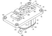
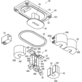
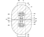
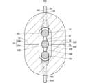
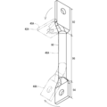
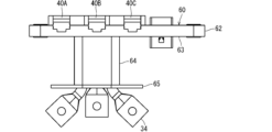
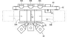
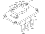
以下、実施形態1に係る端子台20について説明する。図1は端子台20を示す斜視図である。図2は端子台20を示す正面図である。図2において端子台20が固定される機器10の筐体11と、接続相手部品である接続相手端子14、15と、配線部品16、17とが2点鎖線で示されている。図3および図4は端子台20を示す分解斜視図である。図5は図2のV-V線断面図であり、図6は図2のVI-VI線断面図である。
[Embodiment 1]
The
<端子台の全体構成について>
端子台20は、機器10の筐体11に取付けられる。機器10は、例えば、回転電機またはインバータである。筐体11は、機器10の内部部品を覆うケースである。筐体11に取付孔11hが形成されている。筐体11のうち取付孔11hの周囲部分に端子台20が取付けられる。端子台20は、取付孔11hを介して、機器10内の電気部品と、機器10外の電気部品とを電気的に接続する。
<Overall configuration of the terminal block>
The
例えば、機器10が回転電機であり、端子台20が、回転電機内の電気部品と回転電機外のインバータとを電気的に接続する部品として利用されることがある。この場合に、端子台20を経由する駆動電流からノイズを除去することが要請されることがある。特に、インバータにSiC(シリコンカーバイド)半導体が利用される場合に、ノイズのレベルが大きくなる可能性がある。本端子台20は、環状磁性体コア50を備えており、端子台20を経由する駆動電流からノイズを除去する構成を有している。
For example, the device 10 may be a rotating electric machine, and the
端子台20は、導電路形成体30と、環状磁性体コア50と、絶縁ベース60とを備える。
The
導電路形成体30は、機器10の内外を接続する導電路を形成する部分である。本実施形態では、導電路形成体30は、複数(ここでは3つ)のバスバ端子40A、40B、40Cを含む。導電路形成体は、バスバ端子を1つのみ含む構成であってもよい。
The conductive
導電路形成体30は、第1接続部32と、第2接続部34と、第1接続部32と第2接続部34との間の中間部36とを含む。第1接続部32および第2接続部34は、機器10の内側または外側の電気部品に接続される部分である。中間部36は、第1接続部32と第2接続部34とを電気的に接続する部分である。
The conductive
導電路形成体30が複数のバスバ端子40A、40B、40Cを含む場合、第1接続部32は、複数のバスバ端子40A、40B、40Cの複数の一方側の端部(後述する第1バスバ端部42A、42B、42C)を含む部分である。同様に、第2接続部34は、複数のバスバ端子40A、40B、40Cの複数の他方側の端部(後述する第2バスバ端部44A、44B、44C)を含む部分であり、中間部36は、複数のバスバ端子40A、40B、40Cの複数の中間部(後述するバスバ中間部46A、46B、46C)を含む部分である。
When the conductive
中間部36の延在方向Aに沿って見た場合に、第1接続部32および第2接続部34は、中間部36よりも大きく広がっている。よって、第1接続部32および第2接続部を、接続相手端子14または接続相手端子15との接続に適するレイアウトに配置し易い。また、中間部36を、第1接続部32および第2接続部34よりもくびれた構成とすることで、導電路形成体30の中間部36を小型化し易い。
When viewed along the extending direction A of the
環状磁性体コア50は、磁性材料によって環状に形成された部品である。
The annular
環状磁性体コア50は、導電路形成体30のうちの中間部36を囲むように配置される。これにより、導電路形成体30を流れる電流からノイズ、特に、高周波ノイズを除去する。例えば、導電路形成体30を構成する各バスバ端子40A、40B、40Cと環状磁性体コア50とでインダクタを構成し、導電路形成体30を流れる高周波電流に対して高いインピーダンスを呈することによって、高周波ノイズを除去する。
The annular
環状磁性体コア50は、中間部36に対して絶縁された状態で、当該中間部36を囲む。環状磁性体コア50の内周部に中間部36が配置されるため、当該内周部は、中間部36の通過を許容する形状に形成されている。中間部36に対する絶縁性を保てる条件で、環状磁性体コア50の内周部は中間部36の外周部に近接できる形状であることが好ましい。これにより、中間部36と環状磁性体コア50との距離を小さくでき、小さい環状磁性体コア50でも、インピーダンスを大きくし易いからである。また、環状磁性体コア50の内周部を小さくすることで、環状磁性体コア50を小型化でき、端子台20の小型化および低コスト化に貢献できるからである。
The annular
上記のように、第1接続部32および第2接続部34は、中間部36よりも大きく広がっている。仮に環状磁性体コアの内周部を、第1接続部32および第2接続部34の通過を許容する大きさに設定した場合、当該環状磁性体コアが中間部36を覆った状態で、環状磁性体コアの内周部と中間部36との間隔が大きくなる。すると、環状磁性体コアによるインピーダンスが小さくなってしまう可能性がある。前記間隔が多くなった分を、環状磁性体コアの磁路断面積を大きくすることによって補おうとすると、環状磁性体コアが大型化してしまう可能性がある。また、環状磁性体コアの内周部を大きくした分、環状磁性体コアが大型化する可能性がある。環状磁性体コアが大型化すると、端子台が大型化し、また、コスト増にもなってしまう可能性がある。
As described above, the
そこで、環状磁性体コア50の内周部を、第1接続部32と第2接続部34との通過を制限する程度に小さくする。中間部36に対する絶縁性を保てる範囲で、環状磁性体コア50の内周部をなるべく小さくする。例えば、中間部36の外周部に対して1mmから10mm程度の最小間隔を保てる程度で、環状磁性体コア50の内周部を小さくしてもよい。
Therefore, the inner circumference of the annular
また、環状磁性体コア50が、複数の分割コア50A、50Bを含む構成とする。例えば、環状をなす環状磁性体コア50を、2分割形状とする。環状磁性体コア50は、対称形状に2分割されてもよいし、非対称形状に2分割されてもよい。環状磁性体コアは、3つ以上に分割されてもよい。本実施形態では、環状磁性体コア50は、一対の平行部分の両端に半環状部分が連なるトラック形状を呈している。環状磁性体コア50は、その長辺方向に垂直な2分割面に沿って、対称形状に2分割されている。
The annular
分割コア50A、50Bのそれぞれが磁性材料によって形成される。例えば、分割コア50A、50Bは、フェライトによって形成されてもよいし、積層された電磁鋼板によって形成されてもよいし、ダスト材によって構成されてもよい。
Each of the
そして、分割コア50A、50Bが互いの端面を対向させるように配置された状態で、環状磁性体コア50が中間部36を囲んでいる。つまり、複数の分割コア50A、50Bは、導電路形成体30の中間部36を囲む環状をなすように配置された状態とする。この場合、第1接続部32および第2接続部34は、環状磁性体コア50内を通過しなくてもよいので、環状磁性体コア50の内周部を、第1接続部32および第2接続部34の広がり形状に関わりなく、中間部36の外周部の形状に近付けるように小さくできる。
The annular
また、環状磁性体コア50は、磁性シート52を含む。ここで、複数の分割コア50A、50Bのそれぞれは、環状をなすように配置された状態で、互いに対向する対向面50Fを有している。対向面50Fは、環状磁性体コア50が形成する環状磁路に沿った方向において対向し合う面である。
The annular
磁性シート52は、互いに対向する一対の対向面50Fの間に介在している。磁性シート52は、分割コア50A、50Bよりも柔軟なシート状の磁性体であり、分割コア50A、50Bの間に生じる隙間を埋める。
The
絶縁ベース60は、導電路形成体30と環状磁性体コア50とを保持する部分である。絶縁ベース60によって、導電路形成体30の複数のバスバ端子40A、40B、40Cが絶縁状態で一定の位置関係に保たれる。また、絶縁ベース60によって、環状磁性体コア50が、複数のバスバ端子40A、40B、40Cに対して絶縁された状態で、バスバ端子40A、40B、40Cを囲む一定の位置関係に保たれる。絶縁ベース60は、第1接続部32の少なくとも一部と、第2接続部34の少なくとも一部とを露出させた状態で、中間部36と中間部36を囲む環状磁性体コア50とを保持している。
The insulating
絶縁ベース60は、例えば、導電路形成体30と環状磁性体コア50とのうちの一方または両方をインサート部分として樹脂によって金型成形された部分であってもよい。絶縁ベース60は、例えば、導電路形成体30と環状磁性体コア50とは別に樹脂によって金型成形された部分であってもよい。
The insulating
本実施形態では、絶縁ベース60は、第1樹脂部62と、第2樹脂部66とを含む。
In this embodiment, the insulating
第1樹脂部62は、導電路形成体30をインサート部分として樹脂によって金型成形された部分である。第1樹脂部62が、複数のバスバ端子40A、40B、40Cを相互に絶縁状態で一定の位置関係に保つ。また、第1樹脂部62が、中間部36の周りを覆い、中間部36と環状磁性体コア50とを絶縁するように隔てる。
The
より具体的には、第1樹脂部62は、固定板部63と、胴部64と、保持突部65とを含む。
More specifically, the
固定板部63は、取付孔11hよりも大きく広がる板状に形成されている。固定板部63に固定用孔63hが形成されている。固定板部63が取付孔11hの周りで筐体11の外側面を覆うことができる。この状態で、ネジが固定用孔63hを通って筐体11に螺合することで、端子台20が筐体11に固定される。
The fixing
胴部64が固定板部63から突出している。固定板部63が筐体11に取付けられた状態で、胴部64は、取付孔11h内に配置される。導電路形成体30の中間部36が胴部64内に位置する。導電路形成体30は固定板部63を貫通しており、第1接続部32が固定板部63のうち胴部64とは反対側の面に露出している。本実施形態では、第1接続部32は、複数の第1バスバ端部42A、42B、42Cを含んでおり、当該複数の第1バスバ端部42A、42B、42Cがそれぞれ接続相手端子14に電気的に接続される。接続相手端子14は、例えば、インバータから延びる板状のバスバ端子である。第1バスバ端部42A、42B、42Cには、ネジ挿通孔が形成されており、接続相手端子14とネジ締め固定されてもよい。
The
保持突部65は、胴部64のうち固定板部63の反対側の端部から外側に突出している。本実施形態では、保持突部65は、胴部64の端部の周囲から環状に突出している。環状磁性体コア50が胴部64を囲んだ状態で、固定板部63と保持突部65との間に配置される。これにより、環状磁性体コア50が胴部64に対して一定位置に保持される。
The retaining
第2樹脂部66は、環状磁性体コア50の外周部、上側面および下側面を囲むホルダ形状に形成されている。本実施形態では、第2樹脂部66は、2つの分割ホルダ部66A、66Bに分割されている。分割ホルダ部66A、66Bの一側縁が薄肉ヒンジ67aによって開閉可能に連結されている。分割ホルダ部66Aの他側縁に係止凸部66Bpが形成され、分割ホルダ部66Bの他側縁に係止片66Apが延出している。開いた分割ホルダ部66A、66Bを閉じることで、分割ホルダ部66A、66B内に環状磁性体コア50を配置することができる。分割ホルダ部66A、66Bで、環状磁性体コア50を覆った状態で、分割ホルダ部66Aの他側縁の係止凸部66Bpを、分割ホルダ部66Bの他側縁の係止片66Apに形成された係止孔部に係止させることで、分割ホルダ部66A、66Bが閉じた状態に保たれる。
The
導電路形成体30は胴部64を貫通しており、第2接続部34が胴部64の下方に突出している。本実施形態では第2接続部34は、複数の第2バスバ端部44A、44B、44Cを含んでおり、当該複数の第2バスバ端部44A、44B、44Cがそれぞれ接続相手端子15に電気的に接続される。接続相手端子15は、例えば、機器10内の電気部品から延びる板状のバスバ端子である。第2バスバ端部44A、44B、44Cには、ネジ挿通孔が形成されており、接続相手端子15とネジ締め固定されてもよい。
The conductive
固定板部63のうち筐体11側の面に環状シール22が配置されてもよい。環状シール22は、取付孔11hの周りに位置する環状の弾性部品である。環状シール22が固定板部63と筐体11との間に圧縮状態で介在することで、取付孔11hの周りで液体がシールされる。
An annular seal 22 may be disposed on the surface of the fixing
固定板部63に中継コネクタ24が保持されていてもよい。中継コネクタ24は、機器10内の配線部品16と、機器10外の配線部品17とを中継接続するコネクタである。例えば、中継コネクタ24は、配線部品16側のコネクタと機器10外の配線部品17側のコネクタとの両方に接続可能な構成を有しており、配線部品16の回路と配線部品17の回路とが、中継コネクタ24内の中継端子を介して電気的に接続される。
The fixing
固定板部63は、中継コネクタ24をインサート部分として金型成形されてもよい。端子台20が中継コネクタ24を備えることは必須ではない。
The fixing
<磁性シートについて>
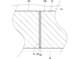
磁性シート52についてより具体的に説明する。図7は図5の断面図において分割コア50A、50B間に位置する磁性シート52を示す拡大図である。
<About the magnetic sheet>
A more detailed description will be given of the
磁性シート52は、基材と当該基材内に分散している磁性粉とを含むシートである。基材は、例えば、シリコーン等の樹脂、または、ゴムであってもよい。基材は、分割コア50A、50Bよりも柔軟であることが好ましい。磁性粉は、例えば、フェライト等である。
The
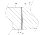
磁性シート52が一対の対向面50Fの間に介在することで、当該磁性シート52が一対の対向面50Fの隙間に応じて変形する。例えば、図8に示すように、一対の対向面50Fが非平行な関係である場合、一対の対向面50Fの間隔が各部で異なる可能性がある。磁性シート52が一対の対向面50Fの間に挟込まれることで、磁性シート52が一対の対向面50Fの各部の間隔に応じて圧縮される。これにより、一対の対向面50Fの隙間のうちの大部分に磁性シート52が配置され、一対の対向面50Fの間に空気が存在するエアギャップが生じ難くなる。磁性シート52の透磁率は、空気の透磁率よりも高いため、一対の対向面50Fの間で磁気抵抗を小さくできる。
When the
また、一対の対向面50Fに凹凸が生じている場合、一対の対向面50Fの間に挟込まれた磁性シート52は、当該凹凸形状に従って変形できる。これにより、一対の対向面50Fの凹みを埋めることができ、一対の対向面50Fの間に空気が存在するエアギャップが生じ難くなる。これによって、一対の対向面50Fの間で磁気抵抗を小さくできる。これにより、環状磁性体コア50によるノイズ低減効果が向上する。
In addition, if the pair of opposing
また、分割コア50A、50Bおよび絶縁ベース60の熱膨張収縮差等に起因して一対の対向面50Fの間隔が変動する場合がある。この場合に、磁性シート52が、当該一対の対向面50Fの間隔に応じて変形することで、一対の対向面50Fの間に空気が存在するエアギャップが形成されることを抑制できる。
The distance between the pair of opposing
磁性シート52は、一対の対向面50Fの外縁に沿った形状を有していてもよい。例えば、一対の対向面50Fが同じ形状であり、磁性シート52は、当該対向面50Fと同じ形状であってもよい。磁性シート52が対向面50Fと同じ形状である場合には、公差範囲内での同じである場合を含む。例えば、磁性シート52の縁が対向面50Fの縁に対して±2mmの範囲内、好ましくは、±2mmの範囲内に位置していてもよい。例えば、磁性シート52は対向面50Fに対して90%以上、好ましくは、95%以上の領域に広がる程度に、対向面50Fの全体に広がる形状とされていてもよい。
The
磁性シート52は、分割コア50A、50Bによる挟込み力によって一対の対向面50Fの間に保持されていてもよい。例えば、第2樹脂部66の2つの分割ホルダ部66A、66Bが配置された状態で、第2樹脂部66が、分割コア50A、50Bを、配置時の合体方向外側から位置規制するように保持する。これにより、隙間の上限が規制された一対の対向面50Fの間に磁性シート52が挟持され得る。
The
また、磁性シート52は、分割コア50A、50Bの一対の対向面50Fの周りを囲む絶縁ベース60によって、一対の対向面50Fの間に位置する状態が保たれてもよい。例えば、環状磁性体コア50の内周側には第1樹脂部62が存在し、環状磁性体コア50の上側、下側および外周側に第2樹脂部56が存在する。このため、一対の対向面50Fの周囲4方は、第1樹脂部62と第2樹脂部56とが存在する。第1樹脂部62と第2樹脂部56とによって、一対の対向面50Fの間から磁性シート52が脱しないように保持されてもよい。
The
磁性シート52は、一対の対向面50Fの一方または両方に接着されてもよい。接着は、例えば、粘着剤を含む接着剤によってなされてもよい。
The
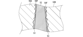
図9に示すように、対向面50Fと磁性シート52との間に磁性接着剤53が介在していてもよい。磁性接着剤53は、磁性シート52の両面側に存在していてもよいし、磁性シート52の片面側にのみ存在していてもよい。図9では、磁性接着剤53は、磁性シート52の両面側に存在しており、磁性シート52の両面を、一対の対向面50Fのそれぞれに接着している。
As shown in FIG. 9, a
磁性接着剤53は、接着基剤と、当該接着基剤内に分散しているフェライト等の磁性粉とを含む接着剤である。接着基剤は、粘着性を有するものであってもよいし、対向面50Fおよび磁性シート52に対して投錨効果、化学的接着または分子間力によって接着するものであってもよい。磁性接着剤53は、対向面50Fと磁性シート52との接着状態で、硬化してもよいし、流動性を保っていてもよい。
The
磁性接着剤53が磁性シート52と対向面50Fとを接着する初期状態において、磁性接着剤53は、磁性シート52よりも柔らかい。対向面50Fの表面に細かい凹凸が生じている場合、磁性接着剤53は、磁性シート52よりも、対向面50Fの表面の細かい凹凸を効果的に埋めることができる。
In the initial state when the
磁性接着剤53は、磁性シート52の表面に塗布されていてもよいし、対向面50Fに塗布されてもよい。
The
磁性シート52と磁性接着剤53とを併用することで、一対の対向面50Fの間隔の大きなばらつきに対しては磁性シート52で対応し、対向面50Fの表面の細かい凹凸については磁性接着剤53によって対応することができる。
By using the
磁性接着剤53は、磁性シート52と同様に、熱膨張収縮差等に起因して一対の対向面50Fの間に空気が存在するエアギャップが形成されることの抑制にも貢献し得る。
Like the
<導電路形成体について>
導電路形成体30についてより詳細に説明する。導電路形成体30は、複数のバスバ端子40A、40B、40Cを含む。複数のバスバ端子40A、40B、40Cのそれぞれは、導電材料の一体物であり、複数の部品が挿入接続によって合体した部品でないことが好ましい。例えば、複数のバスバ端子40A、40B、40Cのそれぞれは、単一金属材のプレス加工部品であってもよい。複数のバスバ端子40A、40B、40Cのそれぞれが、単一金属材のプレス加工部品であれば、挿入接続のためのばね構造、接点構造を形成しなくてもよいので、コスト低減が可能になる。また、接点部における発熱が抑制される。
<Conductive path forming body>
The conductive
バスバ端子40A、40B、40Cのそれぞれは、第1バスバ端部42A、42B、42Cと、第2バスバ端部44A、44B、44Cと、バスバ中間部46A、46B、46Cと、を含む。バスバ中間部46A、46B、46Cは、第1バスバ端部42A、42B、42Cと、第2バスバ端部44A、44B、44Cとの間に位置している。バスバ端子40Aとバスバ端子40Cとは、バスバ端子40Bの中心軸を通る面に対して鏡面対称性を有していてもよい。第1バスバ端部42A、42B、42Cと、第2バスバ端部44A、44B、44Cのそれぞれは、バスバ中間部46A、46B、46Cに対して当該バスバ中間部46A、46B、46Cの延在方向Aに対して交差する方向に広がっている。
Each of the
上記複数のバスバ中間部46A、46B、46Cが間隔をあけて互いに平行な状態で延びている。本実施形態では、複数のバスバ中間部46A、46B、46Cが、この順で、間隔をあけて一列に並んでいる。間隔は、所望の絶縁距離に応じた大きさに設定される。
The multiple busbar
第1接続部32が中間部36よりも大きく広がるように、複数の第1バスバ端部42A、42B、42Cとのうちの少なくとも1つが複数のバスバ中間部46A、46B、46Cに対して交差する方向に延びている。
At least one of the multiple first busbar ends 42A, 42B, 42C extends in a direction intersecting the multiple busbar
また、第2接続部34が中間部36よりも大きく広がるように、複数の第2バスバ端部44A、44B、44Cとのうちの少なくとも1つが複数のバスバ中間部46A、46B、46Cに対して交差する方向に延びている。
In addition, at least one of the multiple second busbar ends 44A, 44B, 44C extends in a direction intersecting the multiple busbar
ここで、第1接続部32、第2接続部34および中間部36の広がりは、中間部36の延在方向Aに沿って見た場合における広がりであってもよい。また、広がりは、第1接続部32、第2接続部34または中間部36の各構成部分が広がる範囲である。例えば、広がりの大きさは、中間部36の延在方向Aに沿って見た場合に、第1接続部32、第2接続部34または中間部36の各構成部分を包含し得る凸包(convex hull、図5のQ1、Q2、図6のQ1、Q3参照)の面積によって評価されてもよい。
Here, the extent of the
第1接続部32、第2接続部34および中間部36の広がりの大きさは、中間部36の延在方向Aに沿って見た場合において、第1接続部32、第2接続部34または中間部36の各構成部分を包含し得る外接円の面積によって評価されてもよい。
The extent of the spread of the
本実施形態では、第1接続部32は、中間部36に対して端部で広がっている部分であり、絶縁ベース60から上側に突出する部分を含む。第1接続部32は、第1バスバ端部42A、42B、42Cを含む。
In this embodiment, the
第1バスバ端部42A、42B、42Cは、バスバ中間部46A、46B、46Cに対して交差する方向、ここでは、直交する方向に向うように曲っている。第1バスバ端部42Aは、バスバ中間部46A、46B、46Cが並ぶ方向の一方側に向うように曲っている。第1バスバ端部42Cは、第1バスバ端部42Aとは逆側に曲っている。第1バスバ端部42Bは、バスバ中間部46A、46B、46Cが並ぶ方向に対して直交する方向に曲っている。
The first bus bar ends 42A, 42B, 42C are bent in a direction that intersects with the bus bar
中間部36は、バスバ中間部46A、46B、46Cを含んでおり、当該中間部36の凸包Q1は、バスバ中間部46A、46B、46Cが並ぶ方向において外側のバスバ中間部46A、46Cの外側縁によって囲まれる範囲である(図5参照)。
The
第1接続部32の凸包Q2は、第1バスバ端部42A、42B、42Cの先端の角を結んだ凸多角形によって囲まれる範囲である。第1バスバ端部42A、42B、42Cの先端の角は、バスバ中間部46A、46B、46Cから外側に離れた位置に存在するため、凸包Q2は、凸包Q1よりも大きい。よって、第1接続部32は中間部36よりも大きく広がっている。
The convex hull Q2 of the
また、第2接続部34は、中間部36に対して端部側で広がる部分であり、絶縁ベース60から下側に突出する部分を含む。第2接続部34は、第2バスバ端部44A、44B、44Cを含む。
The
第2バスバ端部44A、44Cは、バスバ中間部46A、46B、46Cに対して交差する方向、ここでは、45度交差する方向に向うように曲っている。第2バスバ端部44Aは、バスバ中間部46A、46B、46Cが並ぶ方向の一方側に向うように斜めに曲っている。第2バスバ端部44Cは、第2バスバ端部44Aとは逆側に曲っている。第2バスバ端部44Bは、バスバ中間部46Bに対して曲らずに真っ直ぐ延びている。
The second bus bar ends 44A, 44C are bent in a direction that intersects with the bus bar
第2接続部34の凸包Q3は、第2バスバ端部44A、44Cの先端の角と、第2バスバ端部44A、44B、44Cのうち絶縁ベース60から出る基端部分の外縁を囲む範囲である(図6参照)。第2バスバ端部44A、44Cの先端の角は、バスバ中間部46A、46B、46Cから外側に離れた位置に存在し、第2バスバ端部44A、44B、44Cのうち絶縁ベース60から出る基端部分もバスバ中間部46A、46B、46Cと同程度の範囲に存在しているため、凸包Q3は、凸包Q1よりも大きい。よって、第2接続部34は中間部36よりも大きく広がっている。
The convex hull Q3 of the
本実施形態では、バスバ端子40A、40B、40Cは、扁平端部と、扁平端部よりも円柱に近い円柱状中間部とを含む円柱状バスバ端子である。
In this embodiment,
円柱状中間部が、扁平端部よりも円柱に近いとは、円柱状中間部の横断面形状(延在方向Aに対して直交する方向の断面)が、扁平端部の横断面形状よりも円近い形状であることをいう。扁平端部は、円柱状中間部よりも扁平である。扁平度合は、扁平端部または円柱状中間部の横断面形状における最も長い方向の長手方向寸法に対する、当該長い方向に対して直交する方向の短手方向寸法の比で評価されてもよい。長手方向寸法に対する短手方向寸法の比が小さい方が扁平であると評価されてもよい。 The cylindrical middle section being closer to a cylinder than the flattened end section means that the cross-sectional shape (cross section perpendicular to the extension direction A) of the cylindrical middle section is closer to a circle than the cross-sectional shape of the flattened end section. The flattened end section is flatter than the cylindrical middle section. The degree of flatness may be evaluated as the ratio of the short side dimension in the direction perpendicular to the longest direction to the longitudinal dimension in the longest direction of the cross-sectional shape of the flattened end section or cylindrical middle section. The smaller the ratio of the short side dimension to the longitudinal dimension, the flatter it may be evaluated to be.
本実施形態では、バスバ中間部46A、46B、46Cのうち第1バスバ端部42A、42B、42C寄りの部分を除く部分と、第2バスバ端部44A、44B、44Cのうちの基端寄りの部分とが円柱状中間部であり、横断面が円形に形成されている。また、第1バスバ端部42A、42B、42Cは、方形板状をなす扁平端部である。また、第2バスバ端部44A、44B、44Cの先端寄り部分も、方形板状をなす扁平端部である。
In this embodiment, the busbar
バスバ端子40A、40Cのうちの第2バスバ端部44A、44C側では、円柱状中間部の端部、すなわち、第2バスバ端部44A、44Cの基端部が曲ることで、扁平端部としての第2バスバ端部44A、44Cが円柱状中間部のうちの中間部を含むバスバ中間部46A、46Cに対して交差する方向に延びている。円柱状中間部の端部は、横断面円形状であるため、バスバ中間部46A、46Cに対して各種方向に曲げ易い。このため、第2バスバ端部44A、44Cを互いに異なる方向に容易に曲げることができる。
At the
バスバ端子40A、40B、40Cのうちの第1バスバ端部42A、42B、42C側では、扁平端部がその厚み方向に曲って、扁平端部の先端部である第1バスバ端部42A、42B、42Cが円柱状中間部の延在方向Aに対して交差する方向に延びている。
At the first
例えば、円柱状中間部を任意の方向にプレスすることで、円柱状中間部に対する扁平端部の扁平方向を任意の方向に加工できる。扁平端部の扁平方向を、曲げを望む方向に設定することで、扁平端部の曲げ方向を任意の方向に容易に設定し易い。 For example, by pressing the cylindrical middle section in any direction, the flattening direction of the flattened end section relative to the cylindrical middle section can be processed in any direction. By setting the flattening direction of the flattened end section to the desired bending direction, the bending direction of the flattened end section can be easily set to any direction.
上記をバスバ端子40Aの製造方法を例にしてより具体的に説明する。
The above will be explained in more detail using the manufacturing method of
まず、図10に示すように、円柱状金属材90を準備する。円柱状金属材90は丸棒状の金属材である。円柱状金属材90は、銅、銅合金、アルミニウム、アルミニウム合金等によって形成されてもよい。
First, as shown in FIG. 10, a
そして、円柱状金属材90の端部を扁平形状にプレス加工する。円柱状金属材90の中間部に対するプレス方向を任意に設定することで、円柱状金属材90の両端部の扁平方向を、相互に任意に異ならせることができる。例えば、円柱状金属材90の両端部の扁平方向を、円柱状金属材90の中心軸周りに90度ずらした位置に設定することができる。
Then, the ends of the
図11に示すように、円柱状金属材90の両端に扁平端部92、94が形成され、その間に円柱状中間部96が形成される。
As shown in FIG. 11, flat ends 92, 94 are formed at both ends of the
そして、扁平端部92の基端部をその厚み方向に曲げることで、扁平端部92の先端部が円柱状中間部96に対して交差する方向に延びるようになる。これにより、円柱状中間部96の上端部に扁平端部92の基端部が連なるバスバ中間部46Aの上側に、当該バスバ中間部46Aに対して交差する方向に延びる第1バスバ端部42Aを形成することができる。
Then, by bending the base end of the
扁平端部92は、円柱状金属材90を扁平にプレス加工することによって形成されるため、扁平端部92の扁平方向は、加工時のプレス方向を調整することで、容易に調整され得る。曲げたい方向に扁平になるように扁平端部92を形成することで、第1バスバ端部42Aを任意の方向に延びるように容易に加工できる。例えば、バスバ端子40Cにおいて、第1バスバ端部42Cを、第1バスバ端部42Aとは逆側に容易に曲げることができる。また、例えば、バスバ端子40Bにおいて、扁平端部の扁平方向を異ならせることで、第1バスバ端部42Bを、第1バスバ端部42A、42Cとは異なる方向に容易に曲げることができる。第1バスバ端部42Aに必要に応じてネジ止固定用の孔が形成される。
The
また、円柱状中間部96の端部を曲げることで、扁平端部94が円柱状中間部96のうちの中間部に対して交差する方向に延びるようになる。これにより、円柱状中間部96の下端部に扁平端部94が連なる第2バスバ端部44Aが形成される。曲げ箇所は、円柱状中間部96の端部に設定されるため、その曲げ方向は任意に設定され得る。このため、バスバ端子40Cにおいて、第2バスバ端部44Cを、第2バスバ端部44Aとは逆側に容易に曲げることができる。第2バスバ端部44Aに必要に応じてネジ止固定用の孔が形成される。
In addition, by bending the end of the cylindrical
このように、円柱状金属材90を曲げて、円柱状金属材90の端部を、円柱状金属材90の中間部の延長上から外れた位置に容易に配置できる。
In this way, the
なお、円柱状金属材90の端部を扁平にする加工と、円柱状金属材90を曲げる加工とはいずれが先に行われてもよい。
It is noted that either the process of flattening the end of the
図3および図4に示すように、バスバ端子40A、40B、40Cとして、円柱状バスバ端子を用いれば、第1バスバ端部42A、42B、42Cおよび第2バスバ端部44A、44B、44Cの曲げ方向を任意に設定し易い。
As shown in Figures 3 and 4, if cylindrical bus bar terminals are used as the
このため、バスバ中間部46A、46B、46Cの延在方向Aにおける曲げ箇所を同じ位置に揃えつつ、第1バスバ端部42A、42B、42Cを同方向において同じ位置に揃えたり、第2バスバ端部44A、44B、44Cを同じ位置に揃えたりすることが容易となる。
This makes it easy to align the bends of the busbar
例えば、第1バスバ端部42A、42B、42Cに着目する。第1バスバ端部42A、42B、42C側の曲げ箇所42Vは、バスバ中間部46A、46B、46Cの延在方向Aにおいて同じ位置に揃っている。そして、第1バスバ端部42A、42B、42Cが同方向において同じ位置に位置している。なお、曲げ箇所42Vが同じ位置、および、第1バスバ端部42A、42B、42Cが同じ位置とは、公差範囲内で同じである場合を含み、例えば、±5mmの範囲内で同じ場合を含む。
For example, let us look at the first bus bar ends 42A, 42B, 42C. The bend points 42V on the first bus bar ends 42A, 42B, 42C side are aligned at the same position in the extension direction A of the bus bar
この場合、上記第1バスバ端部42A、42B、42Cのうちの任意の1つが第1円柱状バスバ端子の一例であり、任意の他の1つが第2円柱状バスバ端子の一例であると考えることができる。 In this case, any one of the first bus bar ends 42A, 42B, 42C can be considered to be an example of a first cylindrical bus bar terminal, and any other one can be considered to be an example of a second cylindrical bus bar terminal.
また、例えば、第2バスバ端部44A、44B、44Cに着目する。第2バスバ端部44A、44C側の曲げ箇所44Vは、バスバ中間部46A、46B、46Cの延在方向Aにおいて同じ位置に揃っている。第2バスバ端部44A、44Cとは同方向において同じ位置に位置している。第2バスバ端部44Bは、接続相手端子15の位置に応じて、上記方向において第2バスバ端部44A、44Cに対してずれている。
Furthermore, for example, attention is given to the second bus bar ends 44A, 44B, 44C. The bend points 44V on the second bus bar ends 44A, 44C side are aligned at the same position in the extension direction A of the bus bar
この場合、第2バスバ端部44A、44Cのうちの一方が第1円柱状バスバ端子の一例であり、他方が第2円柱状バスバ端子の一例であると考えることができる。 In this case, one of the second bus bar ends 44A, 44C can be considered to be an example of a first cylindrical bus bar terminal, and the other can be considered to be an example of a second cylindrical bus bar terminal.
このように、バスバ中間部46A、46B、46Cの延在方向Aにおいて、円柱状中間部の端部が同じ箇所で曲って曲げ箇所44Vをなしているか、扁平端部が同じ箇所で曲って曲げ箇所42Vをなしている。この場合、バスバ端子が各端部で異なる位置で曲る場合と比較して、環状磁性体コア50の設置スペースを圧迫し難い。換言すれば、直線的に延びるバスバ中間部46A、46B、46Cの長さを大きく設定し易い。これにより、複数の円柱状中間部96、すなわち、中間部36の延在方向Aにおいて、環状磁性体コア50を大きくできる。環状磁性体コア50の高さを大きくできれば、環状磁性体コア50の外周形状の小型化が可能になる。
In this way, in the extension direction A of the busbar
<端子台の製造方法>
上記端子台20の製造方法の一例について説明する。
<Terminal block manufacturing method>
An example of a manufacturing method for the
図12に示すように、複数のバスバ端子40A、40B、40Cを集合させる。集合は、バスバ中間部46A、46B、46Cを、間隔をあけて互いに平行状態に配置することによってなされる。複数のバスバ端子40A、40B、40Cの集合配置作業は、例えば、第1樹脂部62を金型成形するための金型98にバスバ端子40A、40B、40Cをセットすることによってなされてもよい。金型98には、中継コネクタ24がセットされてもよい。
As shown in FIG. 12, multiple
そして、バスバ端子40A、40B、40Cのバスバ中間部46A、46B、46Cをインサート部分として、金型98内に溶融された樹脂が供給される。これにより、バスバ中間部46A、46B、46Cを内部に配置した状態で、第1樹脂部62が金型成形される。
Then, molten resin is supplied into the
図13に示すように、バスバ端子40A、40B、40Cおよび第1樹脂部62が金型98から取外される。この状態では、第1バスバ端部42A、42B、42Cは固定板部63から露出しており、第2バスバ端部44A、44B、44Cは、胴部64から下側に露出している。固定板部63と保持突部65との間において、バスバ中間部46A、46B、46Cが胴部64によって覆われている。胴部64の外周側であって、固定板部63と保持突部65との間に環状磁性体コア50を配置可能なスペースが形成されている。
As shown in FIG. 13, the
図14に示すように、分割コア50A、50Bが、胴部64の両外側から胴部64に向って移動する。分割コア50A、50Bは、互いの端面を対向させた状態で、環状をなすように配置される。この際、分割コア50A、50Bの端面間に磁性シート52が配置される。
As shown in FIG. 14, the
この後、第2樹脂部66が環状磁性体コア50の外周を覆うように環状磁性体コア50の周りにセットされる。これにより、分割コア50A、50Bが環状をなす配置状態に保たれる。また、環状磁性体コア50が周囲に対し保護および絶縁される。
Then, the
<効果等>
以上のように構成された端子台20および環状磁性体コア50によると、環状磁性体コア50は、複数の分割コア50A、50Bを含み、複数の分割コア50A、50Bは、導電路形成体30を囲む環状をなすように配置されている。このため、導電路形成体30の形状等に拘らず、環状磁性体コア50で導電路形成体30の中間部36を囲むことができる。これにより、端子台20において、環状磁性体コア50の組付時の制約を抑制できる。また、磁性シート52が互いに対向する一対の対向面50Fの間に介在する。磁性シート52は、一対の対向面50Fの間で全体的に行渡りやすく、一対の対向面50Fの間での磁気抵抗の増加を抑制できる。これにより、環状磁性体コア50の磁気抵抗を小さくでき、環状磁性体コア50によるノイズ低減効果を高めることができる。
<Effects, etc.>
According to the
また、磁性シート52が、一対の対向面50Fの外縁に沿った形状を有すれば、磁性シート52が、一対の対向面50Fの全体に介在し易い。これにより、環状磁性体コア50の磁気抵抗をより小さくできる。
In addition, if the
また、対向面50Fと磁性シート52との間に磁性接着剤53がさらに介在すれば、対向面50Fと磁性シート52との間の細かい凹凸が効果的に埋められる。これにより、一対の対向面50Fの間に空気がより介在し難くなり、環状磁性体コア50の磁気抵抗をより小さくできる。
In addition, if
また、バスバ端子40A、40B、40Cの接続相手端子14、15のレイアウトに応じて、第1バスバ端部42A、42B、42Cと第2バスバ端部44A、44B、44Cとをバスバ中間部46A、46B、46Cに対して曲げることができる。この場合に、第1接続部32および第2接続部34が中間部36よりも大きく広がることがある。このような場合に、内周部が小さい環状磁性体コア50を、中間部36の周りに配置できる。この場合、第1接続部32または第2接続部34を、環状をなす環状磁性体コア50に挿通させなくてもよい。これにより、環状磁性体コア50の内周部を小さくでき、環状磁性体コア50の小型化が可能となる。また、環状磁性体コア50と中間部36との距離を小さくでき、ノイズ低減効果を向上させることができる。
In addition, the first
また、環状磁性体コア50の内周部を、第1接続部32と第2接続部34との通過を制限し、かつ、中間部36の通過を許容する形状に形成することで、環状磁性体コア50を中間部36に近接させ易くなる。これにより、環状磁性体コア50の小型化およびノイズ低減効果の向上が可能となる。
In addition, by forming the inner periphery of the annular
また、バスバ端子40A、40B、40Cを、単一金属材のプレス加工部品とすることで、バスバ端子を複数部品の組合せ部品とする場合よりも、容易に加工できる。
In addition, by making the
また、導電路形成体30が、複数のバスバ端子40A、40B、40Cを含み、複数のバスバ中間部46A、46B、46Cが間隔を互いに平行な状態で延びており、第1接続部32が中間部36よりも大きく広がるように、複数の第1バスバ端部42A、42B、42Cのうちの少なくとも1つが複数のバスバ中間部46A、46B、46Cに対して交差する方向に延びており、第2接続部34が中間部36よりも大きく広がるように、複数の第2バスバ端部44A、44B、44Cのうちの少なくとも1つが複数のバスバ中間部46A、46B、46Cに対して交差する方向に延びている。このため、接続相手端子14、15のレイアウトに応じて、第1バスバ端部42A、42B、42Cと第2バスバ端部44A、44B、44Cとをバスバ中間部46A、46B、46Cに対して適宜曲げて配置できる。この場合に、第1接続部32および第2接続部34が中間部36よりも大きく広がることがある。このような場合に、内周部が小さい環状磁性体コア50を、中間部36の周りに配置できる。
In addition, the conductive
また、バスバ端子40A、40Cが円柱状バスバ端子であり、円柱状中間部96の下端部が曲って、または、扁平端部92がその厚み方向に曲っているため、円柱状中間部96に対する扁平端部92、94の方向を任意の方向に加工し易い。
In addition, the
上記実施形態1では、端子台20が、3つのバスバ端子40A、40B、40Cを備える例が説明された。端子台が備えるバスバ端子の数は任意である。
In the above embodiment 1, an example was described in which the
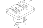
図15および図16に示す変形例に係る端子台120は、2つのバスバ端子40A、40Cを備える。すなわち、端子台120は、上記端子台20において中間のバスバ端子40Bが省略され、幅方向において小型化された構成とされている。また、端子台120では、中継コネクタ24も省略されている。
The modified
本変形例においても、2つのバスバ端子40A、40Cの第1バスバ端部42A、42Cが、バスバ中間部46A、46Cに対して曲っている。このため、2つのバスバ端子40A、40Cを備える導電路形成体130の第1接続部132が、中間部136よりも広がっている。また、2つのバスバ端子40A、40Cの第2バスバ端部44A、44Cが、バスバ中間部46A、46Cに対して曲っている。このため、導電路形成体130の第2接続部134が、中間部136よりも広がっている。
In this modified example, the first bus bar ends 42A, 42C of the two
環状磁性体コア150は、上記中間部136を囲う環状形状に形成されている。環状磁性体コア150は、分割コア150A、150Bを有しており、実施形態1と同様に、分割コア150A、150Bの対向面150Fの間に磁性シート152が介在している。このため、実施形態1と同様に、ノイズ低減のための環状磁性体コア150の組付時の制約を抑制でき、かつ、環状磁性体コア150の磁気抵抗を小さくできる。
The annular magnetic core 150 is formed in an annular shape surrounding the
端子台は、バスバ端子を1つのみ備えていてもよい。例えば、バスバ端子40Aのみを備えていてもよい。この場合でも、第1バスバ端部42Aを含む第1接続部、および、第2バスバ端部44Aを含む第2接続部のそれぞれを、バスバ中間部46Aを含む中間部よりも広がった形状にでき、分割された環状磁性体コアを適用することで、ノイズ低減および環状磁性体コアの小型化が可能となる。
The terminal block may have only one bus bar terminal. For example, it may have only
[実施形態2]
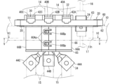
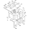
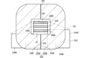
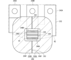
実施形態2に係る端子台220について説明する。図17は実施形態2に係る端子台220を示す斜視図である。図18は同端子台のバスバ端子240A、240B、240Cおよび環状磁性体コア250を示す斜視図である。図19は図18のXIX-XIX線断面図であり、図20は図18のXX-XX線断面図である。なお、本実施形態2では、実施形態1との相違点が中心に説明される。
[Embodiment 2]
A
端子台220は、導電路形成体230と、環状磁性体コア250と、絶縁ベース260とを備える。
The
導電路形成体230は、複数のバスバ端子240A、240B、240Cを含む。端子台20に対する端子台220の主な相違点は、バスバ端子240A、240B、240Cに係る構成である。
The conductive
すなわち、実施形態1のバスバ端子40A、40B、40Cは、円柱状金属材の加工によって形成されていたが、本実施形態2のバスバ端子240A、240B、240Cは、細長い金属板材を曲げることによって形成されている。金属板材は、例えば、銅、銅合金、アルミニウムまたはアルミニウム合金等によって形成される。
That is, while the
細長い金属板材は、その幅方向よりもその厚み方向に曲げ容易である。そこで、次のように構成することで、導電路形成体230の第1接続部232および第2接続部234を、中間部236よりも広げている。
A long, thin metal plate is easier to bend in its thickness direction than in its width direction. Therefore, by configuring it as follows, the
すなわち、バスバ端子240A、240B、240Cのバスバ中間部246A、246B、246Cが、間隔をあけて平行状態に配置されている。バスバ中間部246A、246B、246Cは、厚み方向においては同じ領域に重なって配置される。
That is, bus bar
すなわち、バスバ端子240A、240B、240Cの上端部の第1バスバ端部242A、242B、242Cを厚み方向に、例えば、直角に曲げる。第1バスバ端部242A、242B、242Cの基端部を、上下に間隔をあけて平行状態に配置する。第1バスバ端部242Aの端部をL字状に形成しておき、第1バスバ端部242Bの一側外方に離れた位置に配置する。第1バスバ端部242Cの端部を逆側のL字状に形成しておき、第1バスバ端部242Bの他側外方に離れた位置に配置する。
That is, the first bus bar ends 242A, 242B, 242C at the upper ends of the
第1バスバ端部242A、242B、242Cの端部を、バスバ中間部246A、246B、246Cの延在方向Aにおいて同じ位置に揃えるため、第1バスバ端部242B、242Cに段差部を設ける。
In order to align the ends of the first bus bar ends 242A, 242B, and 242C at the same position in the extension direction A of the bus bar
これにより、バスバ中間部246A、246B、246Cを囲む凸包R1よりも、第1バスバ端部242A、242B、242Cを囲む凸包R2が大きくなる(図20参照)。
As a result, the convex hull R2 surrounding the first bus bar ends 242A, 242B, and 242C is larger than the convex hull R1 surrounding the bus bar
また、バスバ端子240A、240B、240Cの下端部の第2バスバ端部244A、244B、244Cを厚み方向に、例えば、直角に曲げる。第2バスバ端部244A、244B、244Cの基端部を、上下に間隔をあけて平行状態に配置する。第2バスバ端部244Aおよび第2バスバ端部244Cを、第2バスバ端部244Bの両側外方に延出する形状に形成しておく。その延出部分の側縁から延出する部分を、曲げてバスバ中間部246A、246Cの延在方向Aに沿って延びるようにする。また、第2バスバ端部244Bの先端部を曲げてバスバ中間部246Bの延在方向Aに沿って延びるようにする。これにより、第2バスバ端部244A、244B、244Cの端部が、バスバ中間部246A、246B、246Cの延在方向Aに沿って間隔をあけて並列状態で延出する。
In addition, the second bus bar ends 244A, 244B, 244C at the lower ends of the
これにより、バスバ中間部246A、246B、246Cを囲む凸包R1よりも、第2バスバ端部244A、244B、244Cを囲む凸包R3が大きくなる(図19参照)。
As a result, the convex hull R3 surrounding the second bus bar ends 244A, 244B, and 244C is larger than the convex hull R1 surrounding the bus bar
絶縁ベース260は、バスバ中間部246A、246B、246Cと、第1バスバ端部242A、242B、242Cの基端部と、第2バスバ端部244A、244B、244Cの基端部とを相互に絶縁した状態で一定位置に保持している。
The insulating
また、環状磁性体コア250は、実施形態1と同様に、バスバ中間部246A、246B、246Cを囲む分割コア250A、250Bを有している。絶縁ベース260は、分割コア250A、250Bがバスバ中間部246A、246B、246Cを囲む状態も保持する。
The annular
分割コア250A、250Bのうち互いに対向する面が対向面250Fである。対向する一対の対向面250Fの間に、磁性シート52と同様の磁性シート252が介在している。
The opposing surfaces of the
この実施形態2に係る端子台220によると、分割コア250A、250Bの間に磁性シート252が介在しているため、実施形態1と同様に、ノイズ低減のための環状磁性体コア250の組付時の制約を抑制でき、かつ、環状磁性体コア250の磁気抵抗を小さくできる。
In the
その他、円柱状バスバ端子による効果を除き、実施形態1と同様の作用効果を得ることができる。 Other than the effects of the cylindrical bus bar terminal, the same effects as in embodiment 1 can be obtained.
なお、上記実施形態および各変形例で説明した各構成は、相互に矛盾しない限り適宜組合わせることができる。 The configurations described in the above embodiment and each modified example can be combined as appropriate as long as they are not mutually inconsistent.
例えば、同じ端子台において、円柱状バスバ端子と、板状バスバ端子とが併用されてもよい。 For example, cylindrical bus bar terminals and plate-shaped bus bar terminals may be used together on the same terminal block.
10 機器
11 筐体
11h 取付孔
14、15 接続相手端子
16、17 配線部品
20、120、220 端子台
22 環状シール
24 中継コネクタ
30、130、230 導電路形成体
32、132、232 第1接続部
34、134、234 第2接続部
36、136、236 中間部
40A、40B、40C、240A、240B、240C バスバ端子
42A、42B、42C、242A、242B、242C 第1バスバ端部
42V 曲げ箇所
44A、44B、44C、244A、244B、244C 第2バスバ端部
44V 曲げ箇所
46A、46B、46C、246A、246B、246C バスバ中間部
50、250 環状磁性体コア
50F、150F、250F 対向面
50A、50B、250A、250B 分割コア
52、152、252 磁性シート
53 磁性接着剤
60、260 絶縁ベース
62 第1樹脂部
63 固定板部
63h 固定用孔
64 胴部
65 保持突部
66 第2樹脂部
66A、66B 分割ホルダ部
66Ap 係止片
66Bp 係止凸部
67a 薄肉ヒンジ
90 円柱状金属材
92、94 扁平端部
96 円柱状中間部
98 金型
Q1、Q2、Q3、R1、R2、R3 凸包
10 Equipment 11
Claims (9)
環状磁性体コアと、
前記導電路形成体と前記環状磁性体コアとを保持する絶縁ベースと、
を備え、
前記環状磁性体コアは、複数の分割コアと、磁性シートとを含み、
前記複数の分割コアは、前記導電路形成体の中間部を囲む環状をなすように配置されており、
前記複数の分割コアのそれぞれは、環状をなすように配置された状態で、互いに対向する対向面を有しており、
前記磁性シートは、互いに対向する一対の前記対向面の間に介在している、端子台。 A conductive path formation body including a bus bar terminal;
An annular magnetic core;
an insulating base for holding the conductive path formation and the annular magnetic core;
Equipped with
The annular magnetic core includes a plurality of split cores and a magnetic sheet,
The plurality of split cores are arranged to form an annular shape surrounding a middle portion of the conductive path formation body,
The split cores are arranged in an annular shape and have opposing surfaces facing each other,
The magnetic sheet is interposed between a pair of the opposing surfaces that face each other.
前記磁性シートは、前記一対の対向面の外縁に沿った形状を有する、端子台。 2. The terminal block according to claim 1,
The magnetic sheet has a shape that conforms to the outer edges of the pair of opposing surfaces.
前記対向面と前記磁性シートとの間に介在する磁性接着剤をさらに備える端子台。 The terminal block according to claim 1 or 2,
The terminal block further comprises a magnetic adhesive interposed between the opposing surface and the magnetic sheet.
前記導電路形成体は、第1接続部と、第2接続部と、前記第1接続部と前記第2接続部との間の前記中間部とを含み、
前記中間部の延在方向に沿って見た場合に、前記第1接続部および前記第2接続部は、前記中間部よりも大きく広がっており、
前記環状磁性体コアが前記中間部を囲んでおり、
前記絶縁ベースは、前記第1接続部の少なくとも一部と、前記第2接続部の少なくとも一部とを露出させた状態で、前記中間部と前記中間部を囲む前記環状磁性体コアとを保持している、端子台。 The terminal block according to claim 1 or 2,
the conductive path formation includes a first connection portion, a second connection portion, and the intermediate portion between the first connection portion and the second connection portion,
When viewed along an extension direction of the intermediate portion, the first connection portion and the second connection portion are wider than the intermediate portion,
The annular magnetic core surrounds the intermediate portion,
A terminal block, wherein the insulating base holds the intermediate portion and the annular magnetic core surrounding the intermediate portion, with at least a portion of the first connection portion and at least a portion of the second connection portion exposed.
前記環状磁性体コアの内周部は、前記第1接続部と前記第2接続部との通過を制限し、かつ、前記中間部の通過を許容する形状に形成されている、端子台。 The terminal block according to claim 4,
A terminal block, wherein an inner peripheral portion of the annular magnetic core is formed into a shape that restricts passage between the first connection portion and the second connection portion, while allowing passage of the intermediate portion.
前記バスバ端子は、単一金属材のプレス加工部品である、端子台。 The terminal block according to claim 4,
The bus bar terminal is a press-formed part made of a single metal material.
前記導電路形成体は、前記バスバ端子を複数含み、
前記複数のバスバ端子のそれぞれは、第1バスバ端部と、第2バスバ端部と、第1バスバ端部と第2バスバ端部との間のバスバ中間部とを含み、
前記複数のバスバ中間部が間隔をあけて互いに平行な状態で延びており、
前記第1接続部が前記中間部よりも大きく広がるように、前記複数の第1バスバ端部のうちの少なくとも1つが前記複数のバスバ中間部に対して交差する方向に延びており、
前記第2接続部が前記中間部よりも大きく広がるように、前記複数の第2バスバ端部のうちの少なくとも1つが前記複数のバスバ中間部に対して交差する方向に延びている、端子台。 The terminal block according to claim 4,
The conductive path formation body includes a plurality of the bus bar terminals,
Each of the plurality of bus bar terminals includes a first bus bar end portion, a second bus bar end portion, and a bus bar intermediate portion between the first bus bar end portion and the second bus bar end portion,
The plurality of bus bar intermediate portions extend parallel to one another at intervals,
at least one of the plurality of first bus bar end portions extends in a direction intersecting the plurality of bus bar intermediate portions such that the first connection portion is wider than the intermediate portions;
at least one of the plurality of second bus bar end portions extends in a direction intersecting the plurality of bus bar intermediate portions such that the second connection portion extends wider than the intermediate portion.
前記バスバ端子は、円柱状バスバ端子を含み、
前記円柱状バスバ端子は、扁平端部と、前記扁平端部よりも円柱に近い円柱状中間部とを含み、
前記円柱状中間部の端部または前記扁平端部が曲っている、端子台。 3. The terminal block according to claim 1 or 2,
The bus bar terminal includes a cylindrical bus bar terminal,
The cylindrical bus bar terminal includes a flat end portion and a cylindrical intermediate portion that is closer to a cylinder than the flat end portion,
A terminal block, wherein an end of the cylindrical middle portion or the flattened end is curved.
複数の分割コアと、
磁性シートと、
を備え、
前記複数の分割コアは、前記導電路を囲む環状をなすように配置されており、
前記複数の分割コアのそれぞれは、環状をなすように配置された状態で、互いに対向する対向面を有しており、
前記磁性シートは、互いに対向する一対の前記対向面の間に介在している、環状磁性体コア。 An annular magnetic core surrounding a conductive path,
A plurality of split cores;
A magnetic sheet;
Equipped with
the plurality of split cores are arranged in a ring shape surrounding the conductive path,
The split cores are arranged in an annular shape and have opposing surfaces facing each other,
The magnetic sheet is interposed between a pair of the opposing surfaces of the annular magnetic core.
Priority Applications (2)
| Application Number | Priority Date | Filing Date | Title |
|---|---|---|---|
| JP2023149709A JP2025042657A (en) | 2023-09-15 | 2023-09-15 | Terminal block and annular magnetic core |
| PCT/JP2024/031704 WO2025057832A1 (en) | 2023-09-15 | 2024-09-04 | Terminal block and annular magnetic core |
Applications Claiming Priority (1)
| Application Number | Priority Date | Filing Date | Title |
|---|---|---|---|
| JP2023149709A JP2025042657A (en) | 2023-09-15 | 2023-09-15 | Terminal block and annular magnetic core |
Publications (1)
| Publication Number | Publication Date |
|---|---|
| JP2025042657A true JP2025042657A (en) | 2025-03-28 |
Family
ID=95021195
Family Applications (1)
| Application Number | Title | Priority Date | Filing Date |
|---|---|---|---|
| JP2023149709A Pending JP2025042657A (en) | 2023-09-15 | 2023-09-15 | Terminal block and annular magnetic core |
Country Status (2)
| Country | Link |
|---|---|
| JP (1) | JP2025042657A (en) |
| WO (1) | WO2025057832A1 (en) |
Family Cites Families (3)
| Publication number | Priority date | Publication date | Assignee | Title |
|---|---|---|---|---|
| JP5801336B2 (en) * | 2013-03-15 | 2015-10-28 | 三菱電機株式会社 | Bus bar |
| JP6380836B2 (en) * | 2014-07-18 | 2018-08-29 | 北川工業株式会社 | Terminal block with filter |
| JP6630315B2 (en) * | 2017-06-27 | 2020-01-15 | 矢崎総業株式会社 | Noise reduction unit |
-
2023
- 2023-09-15 JP JP2023149709A patent/JP2025042657A/en active Pending
-
2024
- 2024-09-04 WO PCT/JP2024/031704 patent/WO2025057832A1/en active Pending
Also Published As
| Publication number | Publication date |
|---|---|
| WO2025057832A1 (en) | 2025-03-20 |
Similar Documents
| Publication | Publication Date | Title |
|---|---|---|
| TWI460939B (en) | Coaxial connector device | |
| TWI286409B (en) | Pressure contact sandwich type connector | |
| CN101364686B (en) | Rubber plugs for waterproof connectors and waterproof connectors | |
| CN104021933B (en) | Electronic unit and electronic control unit | |
| KR20080093021A (en) | Heating element for electric heating device and method for manufacturing same | |
| US20150027772A1 (en) | Electromagnetic shielding tool and wire harness | |
| EP2856252A2 (en) | Electrical feed-through spacer and connectivity | |
| JPH04137373A (en) | Area array connector | |
| JP2602623B2 (en) | IC socket | |
| JP2003109701A (en) | Connector | |
| CN115803526A (en) | Housing part, in particular housing part for an electronic housing, preferably electric compressor terminal | |
| JP2025042657A (en) | Terminal block and annular magnetic core | |
| TWI327798B (en) | Electrical connector | |
| CN111769387B (en) | Connector system and heater system | |
| JPH09171880A (en) | Molding device of terminal device | |
| JP2025042656A (en) | Manufacturing method of terminal block and bus bar terminal | |
| CN111952815B (en) | Connection method, connection structure, contact, and connector | |
| US20240097361A1 (en) | Lead block and rotary connector device | |
| KR20010034014A (en) | Electric connector | |
| KR100598250B1 (en) | Connector for electro-acoustic components and connecting structures | |
| JP7470534B2 (en) | Capacitor busbar structure | |
| CN103262368B (en) | Ignition coil having coupling device | |
| JP2009295945A (en) | Electronic unit integrated with wire harness, and method for manufacturing thereof | |
| JP2002280091A (en) | Wire connection structure | |
| JP2017112323A (en) | Noise countermeasure component |
Legal Events
| Date | Code | Title | Description |
|---|---|---|---|
| A621 | Written request for application examination |
Free format text: JAPANESE INTERMEDIATE CODE: A621 Effective date: 20260113 |