JP2025041299A - Writing implements - Google Patents
Writing implements Download PDFInfo
- Publication number
- JP2025041299A JP2025041299A JP2023148494A JP2023148494A JP2025041299A JP 2025041299 A JP2025041299 A JP 2025041299A JP 2023148494 A JP2023148494 A JP 2023148494A JP 2023148494 A JP2023148494 A JP 2023148494A JP 2025041299 A JP2025041299 A JP 2025041299A
- Authority
- JP
- Japan
- Prior art keywords
- pen tip
- rod
- shaped extension
- barrel
- writing instrument
- Prior art date
- Legal status (The legal status is an assumption and is not a legal conclusion. Google has not performed a legal analysis and makes no representation as to the accuracy of the status listed.)
- Pending
Links
Images

Landscapes
- Pens And Brushes (AREA)
Abstract
Description
本発明は、チゼル状のペン先を備えた筆記具に関する。 The present invention relates to a writing instrument with a chisel-shaped pen tip.
従来、蛍光ペン等のラインマーカー等においてチゼル状のペン先を有する筆記具が知られている(例えば文献1)。この種の筆記具は、筆記時、ペン先の前端部の向きを目視で確認して筆記するものである。この種の筆記具は、もし、ペン先の前端部における傾斜面と円柱状の外面とが同じ色を有する場合(例えば多孔質体よりなるペン先のインキ含浸状態においてペン先の全体がインキと同じ色を有する場合)、筆記開始時、ペン先の前端部の形状を容易に認識できず(即ちペン先の前端部の向きを容易に調整できず)、所望する筆跡幅を得ることができないおそれがある。また、筆記途中でも、紙面上の筆跡とペン先の前端部とが略同じ色を呈し、両者の区別がつきにくいため、ペン先の前端部の向きを容易に認識できず、所望する筆跡幅を得ることができないおそれがある。 Conventionally, writing implements with chisel-shaped pen tips are known for line markers such as highlighters (for example, see Reference 1). With this type of writing implement, the direction of the front end of the pen tip is visually confirmed when writing. With this type of writing implement, if the inclined surface at the front end of the pen tip and the cylindrical outer surface have the same color (for example, if the entire pen tip, which is made of a porous material, has the same color as the ink when it is impregnated with ink), the shape of the front end of the pen tip cannot be easily recognized when starting to write (i.e., the direction of the front end of the pen tip cannot be easily adjusted), and the desired writing width may not be obtained. Furthermore, even during writing, the handwriting on the paper and the front end of the pen tip have approximately the same color, making it difficult to distinguish between the two, and therefore the direction of the front end of the pen tip cannot be easily recognized, and the desired writing width may not be obtained.
また、文献2には、繊維製ペン先の表面を黒に着色コーティングしたものをチゼル状にカットした蛍光ペンが開示されている。文献2のペン先を用いた筆記具は、コーティング層を設ける構成ため、製造コストが増加し、ユーザー安価に提供できないおそれがある。
Also,
本願発明は、前記従来の問題点を解決するものであって、製造コストの増加を抑え、ペン先の前端部の形状を容易に認識できる筆記具を提供しようとするものである。本願発明で、「前」とはペン先側を指し、「後」とはその反対側を指す。 The present invention aims to solve the above-mentioned problems of the conventional art by providing a writing instrument that suppresses increases in manufacturing costs and allows easy recognition of the shape of the front end of the pen tip. In the present invention, "front" refers to the pen tip side, and "rear" refers to the opposite side.
本発明の第1の態様は、ペン先と、該ペン先が前端部に取り付けられた軸筒と、を備えた筆記具であって、前記ペン先の前端部は、細長の頂面と、該頂面の両側から後方に延びる傾斜面と、該傾斜面の相互間及び該傾斜面の後方に形成される円柱状の外面と、を備え、
前記軸筒は、前端より開口する前端孔と、該前端孔の内面に一体に形成され且つ軸方向に延びる複数の縦リブと、該複数の縦リブのうち、少なくとも1本の縦リブと一体に形成され且つ前記軸筒の前端より前方に突出される棒状延長部と、を備え、前記各々の縦リブが、前記ペン先の傾斜面の後方に形成される円柱状の外面を保持し、前記棒状延長部が外部より視認可能に構成されることを特徴とする筆記具である。
A first aspect of the present invention is a writing instrument comprising a pen tip and a barrel having a front end to which the pen tip is attached, the front end of the pen tip comprising an elongated top surface, inclined surfaces extending rearward from both sides of the top surface, and a cylindrical outer surface formed between the inclined surfaces and rearward of the inclined surfaces;
The barrel has a front end hole that opens from the front end, a plurality of vertical ribs that are integrally formed on the inner surface of the front end hole and extend in the axial direction, and a rod-shaped extension that is integrally formed with at least one of the plurality of vertical ribs and protrudes forward from the front end of the barrel, each of the vertical ribs supporting a cylindrical outer surface formed rearward of the inclined surface of the pen tip, and the rod-shaped extension is configured to be visible from the outside.
前記第1の態様の筆記具によれば、部品点数が増加せず製造コストの増加を抑えるとともに、筆記時(筆記開始時及び筆記途中)において棒状延長部を目印にすることによってペン先の前端部の形状を外部より容易に視認でき、ペン先の前端部(即ちペン先の頂面及び傾斜面)の向きを容易に調整できる。 The writing instrument of the first aspect does not increase the number of parts, suppressing increases in manufacturing costs, and by using the rod-shaped extension as a marker when writing (at the start of writing and during writing), the shape of the front end of the pen tip can be easily seen from the outside, and the orientation of the front end of the pen tip (i.e. the top surface and inclined surface of the pen tip) can be easily adjusted.
本発明の第2の態様は、前記第1の態様の筆記具において、前記棒状延長部の前端が、前記ペン先の傾斜面の相互間の、前記ペン先の最先端部側の円柱状の外面に位置されることを特徴とする。 The second aspect of the present invention is characterized in that in the writing instrument of the first aspect, the front end of the rod-shaped extension is positioned on the cylindrical outer surface of the tip of the pen tip, between the inclined surfaces of the pen tip.
本発明の第2の態様の筆記具は、筆記時において棒状延長部を目印にすることによってペン先の傾斜面の向きを容易に認識することができる。 The writing instrument of the second aspect of the present invention allows the user to easily recognize the orientation of the inclined surface of the pen tip by using the rod-shaped extension as a marker when writing.
本発明の第3の態様は、前記第1の態様または第2の態様の筆記具において、前記棒状延長部が、ペン先から吐出されるインキの色と異なる色を有することを特徴とする。 The third aspect of the present invention is a writing instrument according to the first or second aspect, characterized in that the rod-shaped extension has a color different from the color of the ink ejected from the pen tip.
前記第3の態様の筆記具によれば、インキ含浸状態のペン先の外面の全体がインキ色を呈しても、ペン先の外面と棒状延長部との識別が容易となり、筆記時においてペン先の前端部の形状を確実に認識できる。 With the writing instrument of the third aspect, even if the entire outer surface of the ink-soaked nib is the color of the ink, it is easy to distinguish between the outer surface of the nib and the rod-shaped extension, and the shape of the front end of the nib can be reliably recognized when writing.
本発明の第4の態様は、前記第1乃至第3の何れかの態様の筆記具において、前記軸筒の内面の縦リブの相互間と前記ペン先の円柱状の外面との間に、前記軸筒内部と前記軸筒外部とを空気流通可能にする通気路が形成され、前記棒状延長部を除く前記軸筒の前端開口部を通して前記通気路が外部に開口されることを特徴とする。 The fourth aspect of the present invention is characterized in that in the writing instrument of any one of the first to third aspects, an air passage is formed between the vertical ribs on the inner surface of the barrel and the cylindrical outer surface of the pen tip, allowing air to flow between the inside and outside of the barrel, and the air passage opens to the outside through the front end opening of the barrel excluding the rod-shaped extension.
前記第4の態様の筆記具によれば、軸筒の前端開口部を塞ぐことがなく、通気路を確保することができる。 The writing instrument of the fourth aspect can ensure an air passage without blocking the front end opening of the barrel.
本発明の第5の態様は、前記第1乃至第4の何れかの態様の筆記具において、前記棒状延長部が、対向する前記傾斜面の相互間を二等分する中心線上に設けられることを特徴とする。 The fifth aspect of the present invention is characterized in that in the writing instrument of any one of the first to fourth aspects, the rod-shaped extension is provided on a center line that bisects the space between the opposing inclined surfaces.
前記第5の態様の筆記具によれば、筆記時、棒状延長部を視認することにより、ペン先の傾斜面の向きを容易に認識することができる。 With the writing instrument of the fifth aspect, the orientation of the inclined surface of the pen tip can be easily recognized by visually checking the rod-shaped extension when writing.
本発明の第6の態様は、前記第1乃至第5の何れかの態様の筆記具において、前記棒状延長部が、前記傾斜面を挟むように複数設けられることを特徴とする。 The sixth aspect of the present invention is characterized in that in the writing instrument of any one of the first to fifth aspects, the rod-shaped extension portion is provided in a plurality of positions on either side of the inclined surface.
前記第6の態様の筆記具によれば、筆記時、傾斜面を挟む一対の棒状延長部を視認することにより、ペン先の傾斜面の向きを容易に認識することができる。 With the writing instrument of the sixth aspect, when writing, the orientation of the inclined surface of the pen tip can be easily recognized by visually checking the pair of rod-shaped extensions that sandwich the inclined surface.
本発明の筆記具によれば、製造コストの増加を抑え、ペン先の前端部の形状を容易に認識できる。 The writing instrument of the present invention prevents increases in manufacturing costs and makes it easy to recognize the shape of the front end of the pen tip.
<第1の実施の形態>
本発明の第1の実施の形態の筆記具1を図1乃至図7に示す。
First Embodiment
A
・筆記具
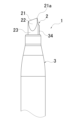
筆記具1は、ペン先2と、該ペン先2が前端部に取り付けられた軸筒3と、該軸筒3内に収容されるインキ吸蔵体5とを備える。
Writing Instrument The
・ペン先
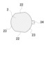
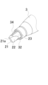
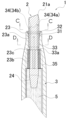
ペン先2は、連続気孔を有する多孔質材料(例えば、繊維束の樹脂加工体、プラスチックポーラス体、またはフェルト加工体等)からなる。ペン先2は、前端部がチゼル状(ノミ状)に形成される。ペン先2は、細長の平面よりなる頂面21と、該頂面21の長辺側の両側より後方に連設される一対の傾斜面22と、該傾斜面22の相互間及び該傾斜面22の後方に形成される円柱状の外面23とを備える。傾斜面22は、後方に向かうに従い径方向外方に向かう形状であり、例えば、傾斜状平面、傾斜状凹曲面、または傾斜状凸曲面等が挙げられる。また、細長の頂面21は、平面以外に、頂部が凸曲面状またはエッジ状の稜線形状であってもよい。
Pen tip The
ペン先2の頂面21は、軸線に対して非垂直面(即ち軸線に対して直角でない面)よりなる。それにより、ペン先2の頂面21の一端(図1におけるペン先2の頂面21の右側端部)は、細長の頂面21の他端より前方に位置され、ペン先2の最先端部21aを構成する。尚、本発明の軸線は、ペン先2の円柱状外面23(大径部23a、小径部23b)及び軸筒3の中心を長手方向に伸びる。
The
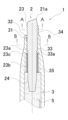
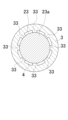
図3に示すように、ペン先2の円柱状の外面23は、大径部23aと、該大径部23aの後方に連設される小径部23bと、大径部23aと小径部23bとの間に形成される外段部23cとを備える。外段部23cが、後述する縦リブの凸部33aに前後方向に当接され、それにより、筆記時及び組立時において、ペン先2の軸筒3内への埋没が防止される。
As shown in Figure 3, the cylindrical
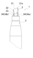
ペン先2の後端部(即ち円柱状の外面23の小径部23bの後方)には、後方に向かうに従い縮径するテーパ面24(円錐状外面)が形成される。ペン先2の後端部がインキ吸蔵体5の前端部に突き刺し接続される。
The rear end of the pen tip 2 (i.e., behind the
・軸筒
軸筒3は、先細状の前端部を有する円筒体であり、合成樹脂(例えばポリプロピレン)の射出成形により得られる。軸筒3の前端部には、前端孔31が軸方向に貫設される。前端孔31は、軸筒3の前端開口部32より外部に開口される。
The
・縦リブ
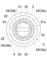
前端孔31の内面には、径方向内方に突出し且つ軸方向に延びる複数本(例えば8本)の縦リブ33が一体に形成される。各々の縦リブ33は、前端孔31の内面に等間隔に形成される。各々の縦リブ33の後端部に径方向内方に突出する凸部33aが一体に形成される。各々の縦リブ33がペン先2の外面(円柱状の外面23)に圧接される。具体的には、縦リブ33の凸部33aより前方部分が、ペン先2の円柱状の外面23の大径部23aに圧接され、縦リブ33の凸部33aの前端が外段部23cに前後に当接され、縦リブ33の凸部33aの径方向内方の頂部がペン先2の円柱状の外面23の小径部23bに圧接される。
A plurality of (e.g., eight)
・棒状延長部
棒状延長部34が、複数の縦リブ33のうち、1本のみの縦リブ33の前端部に一体に形成される。棒状延長部34は、1本の縦リブ33の前端から軸方向前方に延び、軸筒3の前端(即ち前端孔31の前端)より前方に突出される。棒状延長部34が一体に形成されない他の縦リブ33の前端は、軸筒3の前端より前方に突出されていない。
Rod-
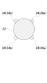
棒状延長部34の内面は、ペン先2の円柱状の外面23に圧接または添設される。棒状延長部34の前端は、ペン先2の傾斜面22の相互間に位置している。即ち、棒状延長部34の前端は、ペン先2の傾斜面22の前端とペン先2の傾斜面22の後端との間の円柱状の外面23に位置している。図2に示すように、棒状延長部34は、筆記具1の平面視(即ちペン先2側から見た場合)において、細長の頂面21(対向する傾斜面22)を二等分する中心線P上に位置される。それにより、筆記時、棒状延長部34を視認することにより、ペン先2の頂面21の位置合わせ(即ち傾斜面22の向きの調整)が容易となる。
The inner surface of the rod-
棒状延長部34の周方向の肉厚は、棒状延長部34の後方に一体に連設された縦リブ33の周方向の肉厚以下に設定されることが好ましい。それにより、棒状延長部34の成形する際の離型が容易となる。
The circumferential thickness of the rod-shaped
また、棒状延長部34の周方向の肉厚は、ペン先2の頂面21の幅寸法(頂面21の対向する長辺間の距離)より小さいことが好ましい。それにより、筆記時、棒状延長部34がシャープな目印となり、視認によるペン先2の頂面21の位置合わせ(即ち傾斜面22の向きの調整)が容易となる。
Furthermore, it is preferable that the circumferential thickness of the rod-shaped
・当接壁部
縦リブ33の後方の軸筒3内面には、軸方向に延びる複数のリブよりなる当接壁部35が一体に形成される。当接壁部35に、インキ吸蔵体5の前端が前後に当接される。
尚、軸筒3は、複数の部材で構成されてもよい。少なくとも、軸筒3は、前端孔31及び縦リブ33を備えた前部が、合成樹脂で一体に形成される構成であればよい。もちろん、軸筒3の全体を合成樹脂で一体に形成されてもよい。
The
・インキ吸蔵体
インキ吸蔵体5は、合成樹脂製繊維束(例えばポリエステル繊維束)と、その外周を包囲する円筒状の外皮とからなる。外皮は合成樹脂製筒体(例えば、ポリプロピレン樹脂の押出成形体)よりなる。前記インキ吸蔵体5にインキが含浸保持される。筆記時、インキがペン先2より吐出され、吐出インキにより、紙面上に筆跡が形成される。
Ink Occluder The
・インキ
インキ吸蔵体5に含浸されるインキは、水性インキ、油性インキのいずれも適用できる。
前記インキ中に含まれる着色剤としては、酸性染料、塩基性染料、直接染料、蛍光染料、一般顔料、蛍光顔料、アルミニウム等の金属粉、パール顔料、酸化チタン等の白色顔料、または可逆熱変色性組成物を内包するマイクロカプセル顔料等が挙げられる。
The ink to be impregnated into the
Examples of colorants contained in the ink include acid dyes, basic dyes, direct dyes, fluorescent dyes, general pigments, fluorescent pigments, metal powders such as aluminum, pearl pigments, white pigments such as titanium oxide, and microencapsulated pigments encapsulating a reversible thermochromic composition.
・棒状延長部の着色
棒状延長部34は、インキ色と異なる色に着色される。例えば、インキ色として、蛍光インキ(例えば蛍光ピンク、蛍光ブルー、蛍光イエロー、蛍光オレンジ、蛍光グリーン、蛍光パープル等)を採用した場合、棒状延長部34は、黒または白に着色される。棒状延長部34の着色は、前端孔31及び縦リブ33が一体に形成された軸筒3を、着色された合成樹脂により成形することによって得ることが好ましい。
Coloring of the rod-shaped extension The rod-shaped
ペン先2は、内部にインキが含浸され、該含浸インキが外部より視認される。軸筒3に前端部より前方に突出されるペン先2の外面は、棒状延長部34が設けられる部分以外は、外部に露出され、含浸インキ(即ちインキ色)が視認される。
The
本実施の形態の筆記具1は、ペン先2と、該ペン先2が前端部に取り付けられた軸筒3と、を備えた筆記具であって、前記ペン先2の前端部は、細長の頂面21と、該頂面21の両側から後方に延びる傾斜面22と、該傾斜面22の相互間及び該傾斜面22の後方に形成される円柱状の外面23と、を備え、前記軸筒3は、前端より開口する前端孔31と、該前端孔31の内面に一体に形成され且つ軸方向に延びる複数の縦リブ33と、該複数の縦リブ33のうち、少なくとも1本の縦リブ33と一体に形成され且つ前記軸筒3の前端より前方に突出される棒状延長部34と、を備え、前記各々の縦リブ33が、前記ペン先2の傾斜面22の後方に形成される円柱状の外面23を保持し、前記棒状延長部34が外部より視認可能に構成された筆記具である。
The
本実施の形態の筆記具1によれば、部品点数が増加せず製造コストの増加を抑えるとともに、筆記時(筆記開始時及び筆記途中)において棒状延長部34を目印にすることによってペン先2の前端部の形状を外部より容易に認識でき、ペン先2の前端部(即ちペン先2の頂面21及び傾斜面22)の向きを容易に調整できる。
The
本実施の形態の筆記具1は、前記棒状延長部34の前端が、前記ペン先2の傾斜面22の相互間の、前記ペン先2の最先端部21a側の円柱状の外面23に位置される構成である。
それにより、本実施の形態の筆記具1は、筆記時において棒状延長部34を目印にすることによってペン先2の傾斜面22の向きを容易に認識することができる。
The
As a result, with the
本実施の形態の筆記具1は、前記棒状延長部34が、ペン先2から吐出されるインキの色と異なる色を有する構成である。それにより、本実施の形態の筆記具1は、インキ含浸状態のペン先2の外面の全体がインキ色を呈しても、ペン先2の外面と棒状延長部34との識別が容易となり、筆記時においてペン先2の前端部の形状を確実に認識できる。
The
本実施の形態の筆記具1は、前記軸筒3の内面の縦リブ33の相互間と前記ペン先2の円柱状の外面23との間に、前記軸筒3内部と前記軸筒3外部とを空気流通可能にする通気路4が形成され、前記棒状延長部34を除く前記軸筒3の前端開口部32を通して前記通気路4が外部に開口される構成である。それにより、本実施の形態の筆記具1は、軸筒3の前端開口部32を塞ぐことがなく、通気路4を確保することができる。
The
本実施の形態の筆記具1は、前記棒状延長部34が、対向する前記傾斜面22の相互間を二等分する中心線上に設けられる構成である。それにより、本実施の形態の筆記具1は、筆記時、棒状延長部34を視認することにより、ペン先2の傾斜面22の向きを容易に認識することができる。
The
<第2の実施形態>
本発明の第2の実施の形態の筆記具1を図8乃至図14に示す。
Second Embodiment
A
・筆記具
筆記具1は、ペン先2と、該ペン先2が前端部に取り付けられた軸筒3と、該軸筒3内に収容されるインキ吸蔵体5とを備える。
Writing Instrument The writing
・ペン先
ペン先2は、連続気孔を有する多孔質材料(例えば、繊維束の樹脂加工体、プラスチックポーラス体、またはフェルト加工体等)からなる。ペン先2は、前端部がチゼル状(ノミ状)に形成される。ペン先2は、細長の平面よりなる頂面21と、該頂面21の長辺側の両側より後方に連設される一対の傾斜面22と、該傾斜面22の相互間及び該傾斜面22の後方に形成される円柱状の外面23とを備える。傾斜面22は、後方に向かうに従い径方向外方に向かう形状であり、例えば、傾斜状平面、傾斜状凹曲面、または傾斜状凸曲面等が挙げられる。また、細長の頂面21は、平面以外に、頂部が凸曲面状またはエッジ状の稜線形状であってもよい。
Pen tip The
ペン先2の頂面21は、軸線に対して非垂直面(即ち軸線に対して直角でない面)よりなる。それにより、ペン先2の頂面21の一端(図8におけるペン先2の頂面21の右側端部)は、細長の頂面21の他端より前方に位置され、ペン先2の最先端部21aを構成する。尚、本発明の軸線は、ペン先2の円柱状外面23(大径部23a、小径部23b)及び軸筒3の中心を長手方向に伸びる。
The
図10に示すように、ペン先2の円柱状の外面23は、大径部23aと、該大径部23aの後方に連設される小径部23bと、大径部23aと小径部23bとの間に形成される外段部23cとを備える。外段部23cが、後述する縦リブの凸部33aに前後方向に当接され、それにより、筆記時及び組立時において、ペン先2の軸筒3内への埋没が防止される。
As shown in Figure 10, the cylindrical
ペン先2の後端部(即ち円柱状の外面23の小径部23bの後方)には、後方に向かうに従い縮径するテーパ面24(円錐状外面)が形成される。ペン先2の後端部がインキ吸蔵体5の前端部に突き刺し接続される。
The rear end of the pen tip 2 (i.e., behind the
・軸筒
軸筒3は、先細状の前端部を有する円筒体であり、合成樹脂(例えばポリプロピレン)の射出成形により得られる。軸筒3の前端部には、前端孔31が軸方向に貫設される。前端孔31は、軸筒3の前端開口部32より外部に開口される。
The
・縦リブ
前端孔31の内面には、径方向内方に突出し且つ軸方向に延びる複数本(例えば8本)の縦リブ33が一体に形成される。各々の縦リブ33は、前端孔31の内面に等間隔に形成される。各々の縦リブ33の後端部に径方向内方に突出する凸部33aが一体に形成される。各々の縦リブ33がペン先2の外面(円柱状の外面23)に圧接される。具体的には、縦リブ33の凸部33aより前方部分が、ペン先2の円柱状の外面23の大径部23aに圧接され、縦リブ33の凸部33aの前端が外段部23cに前後に当接され、縦リブ33の凸部33aの径方向内方の頂部がペン先2の円柱状の外面23の小径部23bに圧接される。
A plurality of (e.g., eight)
・棒状延長部
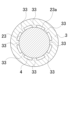
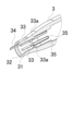
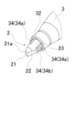
棒状延長部34が、複数(8本)の縦リブ33のうち、4本の縦リブ33の前端部に一体に形成される。棒状延長部34は、4本の縦リブ33の前端から軸方向前方に延び、軸筒3の前端(即ち前端孔31の前端)より前方に突出される。棒状延長部34が一体に形成されない他の4本の縦リブ33は、軸筒3の前端より前方に突出されていない。各々の棒状延長部34は、周方向の位置が等間隔に配置される。
Rod-shaped extension portion The rod-shaped
各々の棒状延長部34の内面は、ペン先2の円柱状の外面23に圧接または添設される。各々の棒状延長部34の前端は、ペン先2の傾斜面22の相互間に位置している。即ち、各々の棒状延長部34の前端は、ペン先2の傾斜面22の前端とペン先2の傾斜面22の後端との間の円柱状の外面23に位置している。
The inner surface of each rod-shaped
図8に示すように、各々の棒状延長部34は、ペン先2の傾斜面22を挟むように設けられる。それにより、筆記時、傾斜面22を挟む一対の棒状延長部34を視認することによって、ペン先2の傾斜面22の向きを容易に調整することができる。
As shown in FIG. 8, each rod-shaped
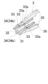
特に、各々の棒状延長部34は、ペン先2の最先端部21a側(図8の右側)の2本の長寸の棒状延長部34aと、ペン先2の最先端部21aの反対側(図8の左側)の2本の短寸の棒状延長部34bとからなる。長寸の棒状延長部34aは、短寸の棒状延長部34bよりも長手寸法(即ち軸筒3前端から各々の棒状延長部34の前端までの軸方向の長さ)が長い。それにより、筆記時、長寸の棒状延長部34aと短寸の棒状延長部34bを同時に視認することにより、ペン先2の傾斜面22の向きを容易に認識でき、ペン先2の傾斜面22の向きを容易に調整することができる。
In particular, each rod-shaped
各々の棒状延長部34の周方向の肉厚は、各々の棒状延長部34の後方に一体に連設された縦リブ33の周方向の肉厚以下に設定されることが好ましい。それにより、各々の棒状延長部34の成形する際の離型が容易となる。
The circumferential thickness of each rod-shaped
また、各々の棒状延長部34の周方向の肉厚は、ペン先2の頂面21の幅寸法(頂面21の対向する長辺間の距離)より小さいことが好ましい。それにより、筆記時、各々の棒状延長部34がシャープな目印となり、視認によるペン先2の頂面21の向きの調整及び傾斜面22の向きの調整が容易となる。
Furthermore, it is preferable that the circumferential thickness of each rod-shaped
・当接壁部
縦リブ33の後方の軸筒3内面には、軸方向に延びる複数のリブよりなる当接壁部35が一体に形成される。当接壁部35に、インキ吸蔵体5の前端が前後に当接される。
尚、軸筒3は、複数の部材で構成されてもよい。少なくとも、軸筒3は、前端孔31及び縦リブ33を備えた前部が、合成樹脂で一体に形成される構成であればよい。もちろん、軸筒3の全体を合成樹脂で一体に形成されてもよい。
The
・インキ吸蔵体
インキ吸蔵体5は、合成樹脂製繊維束(例えばポリエステル繊維束)と、その外周を包囲する円筒状の外皮とからなる。外皮は合成樹脂製筒体(例えば、ポリプロピレン樹脂の押出成形体)よりなる。前記インキ吸蔵体5にインキが含浸保持される。筆記時、インキがペン先2より吐出され、吐出インキにより、紙面上に筆跡が形成される。
Ink Occluder The
・インキ
インキ吸蔵体5に含浸されるインキは、水性インキ、油性インキのいずれも適用できる。
前記インキ中に含まれる着色剤としては、酸性染料、塩基性染料、直接染料、蛍光染料、一般顔料、蛍光顔料、アルミニウム等の金属粉、パール顔料、酸化チタン等の白色顔料、または可逆熱変色性組成物を内包するマイクロカプセル顔料等が挙げられる。
The ink to be impregnated into the
Examples of colorants contained in the ink include acid dyes, basic dyes, direct dyes, fluorescent dyes, general pigments, fluorescent pigments, metal powders such as aluminum, pearl pigments, white pigments such as titanium oxide, and microencapsulated pigments encapsulating a reversible thermochromic composition.
・棒状延長部の着色
棒状延長部34は、インキ色と異なる色に着色される。例えば、インキ色として、蛍光インキ(例えば蛍光ピンク、蛍光ブルー、蛍光イエロー、蛍光オレンジ、蛍光グリーン、蛍光パープル等)を採用した場合、棒状延長部34は、黒または白に着色される。棒状延長部34の着色は、前端孔31及び縦リブ33が一体に形成された軸筒3を、着色された合成樹脂により成形することによって得ることが好ましい。
Coloring of the rod-shaped extension The rod-shaped
ペン先2は、内部にインキが含浸され、該含浸インキが外部より視認される。軸筒3に前端部より前方に突出されるペン先2の外面は、棒状延長部34が設けられる部分以外は、外部に露出され、含浸インキ(即ちインキ色)が視認される。
The
本実施の形態の筆記具1は、ペン先2と、該ペン先2が前端部に取り付けられた軸筒3と、を備えた筆記具であって、前記ペン先2の前端部は、細長の頂面21と、該頂面21の両側から後方に延びる傾斜面22と、該傾斜面22の相互間及び該傾斜面22の後方に形成される円柱状の外面23と、を備え、前記軸筒3は、前端より開口する前端孔31と、該前端孔31の内面に一体に形成され且つ軸方向に延びる複数の縦リブ33と、該複数の縦リブ33のうち、少なくとも1本の縦リブ33と一体に形成され且つ前記軸筒3の前端より前方に突出される棒状延長部34と、を備え、前記各々の縦リブ33が、前記ペン先2の傾斜面22の後方に形成される円柱状の外面23を保持し、前記棒状延長部34が外部より視認可能に構成された筆記具である。
The
本実施の形態の筆記具1によれば、部品点数が増加せず製造コストの増加を抑えるとともに、筆記時(筆記開始時及び筆記途中)において棒状延長部34を目印にすることによってペン先2の前端部の形状を外部より容易に認識でき、ペン先2の前端部(即ちペン先2の頂面21及び傾斜面22)の向きを容易に調整できる。
The
本実施の形態の筆記具1は、前記棒状延長部の前端が、前記ペン先の傾斜面の相互間の、前記ペン先の最先端部側の円柱状の外面に位置される構成である。それにより、本実施の形態の筆記具1は、筆記時において棒状延長部34を目印にすることによってペン先2の傾斜面22の向きを容易に認識することができる。
The
本実施の形態の筆記具1は、前記棒状延長部34が、ペン先2から吐出されるインキの色と異なる色を有する構成である。それにより、本実施の形態の筆記具1は、インキ含浸状態のペン先2の外面の全体がインキ色を呈しても、ペン先2の外面と棒状延長部34との識別が容易となり、筆記時においてペン先2の前端部の形状を確実に認識できる。
The
本実施の形態の筆記具1は、前記軸筒3の内面の縦リブ33の相互間と前記ペン先2の円柱状の外面23との間に、前記軸筒3内部と前記軸筒3外部とを空気流通可能にする通気路4が形成され、前記棒状延長部34を除く前記軸筒3の前端開口部32を通して前記通気路4が外部に開口される構成である。それにより、本実施の形態の筆記具1は、軸筒3の前端開口部32を塞ぐことがなく、通気路4を確保することができる。
The
本実施の形態の筆記具1は、前記棒状延長部34が、各々の傾斜面22を挟むように複数設けられる構成である。それにより、本実施の形態の筆記具1は、筆記時、傾斜面22を挟む一対の棒状延長部34を視認することにより、ペン先2の傾斜面22の向きを容易に認識することができる。
The
1 筆記具
2 ペン先
21 頂面
21a 最先端部
22 傾斜面
23 円柱状の外面
23a 大径部
23b 小径部
23c 外段部
24 テーパ面
3 軸筒
31 前端孔
32 前端開口部
33 縦リブ
33a 凸部
34 棒状延長部
34a 長寸の棒状延長部
34b 短寸の棒状延長部
35 当接壁部
4 通気路
5 インキ吸蔵体
Claims (6)
前記ペン先の前端部は、細長の頂面と、該頂面の両側から後方に延びる傾斜面と、該傾斜面の相互間及び該傾斜面の後方に形成される円柱状の外面と、を備え、
前記軸筒は、前端より開口する前端孔と、該前端孔の内面に一体に形成され且つ軸方向に延びる複数の縦リブと、該複数の縦リブのうち、少なくとも1本の縦リブと一体に形成され且つ前記軸筒の前端より前方に突出される棒状延長部と、を備え、
前記各々の縦リブが、前記ペン先の傾斜面の後方に形成される円柱状の外面を保持し、前記棒状延長部が外部より視認可能に構成されることを特徴とする筆記具。 A writing instrument comprising a pen tip and a barrel having the pen tip attached to a front end thereof,
The front end of the pen tip comprises an elongated top surface, inclined surfaces extending rearward from both sides of the top surface, and a cylindrical outer surface formed between the inclined surfaces and rearward of the inclined surfaces;
The barrel includes a front end hole that opens at a front end, a plurality of longitudinal ribs that are integrally formed on an inner surface of the front end hole and extend in the axial direction, and a rod-shaped extension that is integrally formed with at least one of the longitudinal ribs and protrudes forward from the front end of the barrel,
A writing implement characterized in that each of the vertical ribs holds a cylindrical outer surface formed behind the inclined surface of the pen tip, and the rod-shaped extension portion is configured to be visible from the outside.
The writing implement according to claim 1 , wherein a plurality of the rod-shaped extensions are provided so as to sandwich the inclined surface.
Priority Applications (1)
| Application Number | Priority Date | Filing Date | Title |
|---|---|---|---|
| JP2023148494A JP2025041299A (en) | 2023-09-13 | 2023-09-13 | Writing implements |
Applications Claiming Priority (1)
| Application Number | Priority Date | Filing Date | Title |
|---|---|---|---|
| JP2023148494A JP2025041299A (en) | 2023-09-13 | 2023-09-13 | Writing implements |
Publications (1)
| Publication Number | Publication Date |
|---|---|
| JP2025041299A true JP2025041299A (en) | 2025-03-26 |
Family
ID=95105119
Family Applications (1)
| Application Number | Title | Priority Date | Filing Date |
|---|---|---|---|
| JP2023148494A Pending JP2025041299A (en) | 2023-09-13 | 2023-09-13 | Writing implements |
Country Status (1)
| Country | Link |
|---|---|
| JP (1) | JP2025041299A (en) |
-
2023
- 2023-09-13 JP JP2023148494A patent/JP2025041299A/en active Pending
Similar Documents
| Publication | Publication Date | Title |
|---|---|---|
| KR100758391B1 (en) | Writing implements of double head type | |
| KR102206443B1 (en) | Writing implement | |
| KR0153462B1 (en) | Writing utensils | |
| JP3133495U (en) | Ink tank exchangeable writing instrument | |
| JP4585777B2 (en) | Writing instrument | |
| JP2025041299A (en) | Writing implements | |
| JP6688335B2 (en) | Writing instrument | |
| JP2018103429A (en) | Marking pen | |
| TWI827627B (en) | Note utensils | |
| JP7756051B2 (en) | writing implements | |
| JP2019135093A (en) | Pen tip and writing instrument with the pen tip | |
| JP7403990B2 (en) | writing implements | |
| JP2017124544A (en) | Writing instrument | |
| WO2022138534A1 (en) | Writing implement | |
| CN210881415U (en) | Writing instruments and nibs | |
| JP2022001441A (en) | Pen core for coating instrument | |
| JP2018118420A (en) | Writing instrument | |
| JP2591066Y2 (en) | Ball pen refill | |
| EP4316862A1 (en) | Attachment structure in writing tool, writing tool, and soft member | |
| JP2517465Y2 (en) | Shafts such as writing instruments | |
| JP5340010B2 (en) | Writing instrument and method for manufacturing the same | |
| JP4750355B2 (en) | Double-head writing instrument | |
| JP2555470Y2 (en) | Ballpoint pen | |
| JP2000006574A (en) | Direct liquid writing instrument | |
| JP2007261056A (en) | Synthetic resin nib |