JP2005297450A - Marking pen - Google Patents
Marking pen Download PDFInfo
- Publication number
- JP2005297450A JP2005297450A JP2004119459A JP2004119459A JP2005297450A JP 2005297450 A JP2005297450 A JP 2005297450A JP 2004119459 A JP2004119459 A JP 2004119459A JP 2004119459 A JP2004119459 A JP 2004119459A JP 2005297450 A JP2005297450 A JP 2005297450A
- Authority
- JP
- Japan
- Prior art keywords
- ink
- core
- ink storage
- marking pen
- tip
- Prior art date
- Legal status (The legal status is an assumption and is not a legal conclusion. Google has not performed a legal analysis and makes no representation as to the accuracy of the status listed.)
- Withdrawn
Links
Images
Landscapes
- Pens And Brushes (AREA)
Abstract
Description
本発明は、筆記具用多色マーキングペンに関する。更に詳しくは、2つの異なる色のインキを2つのインキ貯蔵部にそれぞれ貯蔵して、一回の線引きにより一方の色を他方の色で帯状に縁取りされた筆跡等を連続的に描くことができるマーキングペンに関する。 The present invention relates to a multicolor marking pen for a writing instrument. More specifically, two different color inks can be stored in two ink storage units, respectively, and handwriting with one color being striped with the other color can be drawn continuously by one line drawing. Regarding marking pens.
従来、筆記具用インキは、安定な単一色相を呈することが必要とされ、筆記具インキに使用される着色剤は、単独あるいは数種の顔料や染料を混合して調色されてきた。
一方、マーキングペンで色の異なる描線を引くために複数のペン先を備えたものも存在する。
例えば、互いに異色のインキを浸透する一対以上のインキ浸透部よりなる浸透部材を軸筒に内装し、該浸透部材の前記インキ浸透部に嵌入したそれぞれのチップの先端を導出して軸筒の先端に並設してなるマーキングペンが開示されている(特許文献1参照)。
縦方向に毛細管現象によりインキを流通させる微小スリットを貫通させた複数個の熱可塑性樹脂の押出成型によって得たペン先単体を、その先端部において相互に密着させて一体化しペン先とし、それぞれのペン先単体の末端部を該単体と同数のインキ吸蔵体を区画壁を介在させて一体化したインキ筒の先端部に接触させることを特徴する多色サインペンが開示されている(特許文献2参照)。
Conventionally, ink for writing instruments is required to exhibit a stable single hue, and colorants used in writing instrument inks have been toned by mixing alone or several kinds of pigments and dyes.
On the other hand, some marking pens are provided with a plurality of pen points to draw drawn lines having different colors.
For example, a penetrating member composed of a pair of ink penetrating portions that permeate different colors of ink from each other is provided in the shaft tube, and the tip of each chip fitted into the ink penetrating portion of the penetrating member is derived to lead the tip of the shaft tube A marking pen formed side by side is disclosed (see Patent Document 1).
The pen nibs obtained by extrusion molding of a plurality of thermoplastic resins through which micro slits that circulate ink by capillary action in the vertical direction are brought into close contact with each other to be integrated into pen nibs. There is disclosed a multicolor sign pen characterized in that the end of a single nib is brought into contact with the tip of an ink cylinder in which the same number of ink occlusion bodies as that of the single is interposed via a partition wall (see Patent Document 2). ).
また、幅広描線用ペン先部と、幅狭描線用ペン先部とを一直線上の近接した位置に並設し、且つ各ペン先部の先端位置を面一となし、幅広描線用ペン先部と幅狭描線用ペン先部に夫々色の異なるインキを供給せしめることを特徴とするマーキングペン開示されている(特許文献3参照)。 Also, the wide drawing line nib part and the narrow drawing line nib part are juxtaposed in close proximity on a straight line, and the tip position of each pen nib part is flush, and the wide drawing line nib part A marking pen is disclosed in which inks of different colors are supplied to the pen tip portion for narrow drawn lines (see Patent Document 3).
しかし、上記いずれの先行技術も、ペン先の先端でペン先先端構造が複雑で、製造工程も多く、更に筆記する際のペン先の角度により単色となったり、複数の帯状の色の描線となったり、その筆記線が一定しづらいという不都合があった。
本発明は上記課題を解決して、1回の線引きにより縁取りがされた多色の筆記線等を容易に描くことが可能なマーキングペンを提供することを目的とする。
However, in any of the above prior arts, the tip of the nib is complicated at the tip of the nib, the manufacturing process is many, and it becomes a single color depending on the angle of the nib at the time of writing, There was a disadvantage that the writing line was hard to be constant.
An object of the present invention is to solve the above-described problems and to provide a marking pen that can easily draw multicolored writing lines and the like bordered by one line drawing.
本発明者らは上記課題を解決するために鋭意検討した結果、軸筒本体内にインキ貯蔵部を2段に分離して設け、インキ誘導芯のペン先先端部近傍からペン先側のインキ貯蔵部を貫通する部分を内側芯と外側芯に仕切られた二重構造とし、更にその内側芯のみを他方のインキ貯蔵部に延長して挿入させて、外側芯はペン先側のインキ貯蔵部からインキを供給し、内側芯は他方のインキ貯蔵部からインキを供給するマーキングペンとすることにより、1回の線引きにより安定的に縁取りがされた多色の筆記線等を描くことが可能なことを見出し、本発明を完成させた。 As a result of intensive studies to solve the above problems, the inventors of the present invention have provided the ink storage portion in two stages in the shaft cylinder body, and the ink storage on the pen tip side from the vicinity of the tip of the pen tip of the ink guide core. The part that penetrates the part has a double structure partitioned into an inner core and an outer core, and only the inner core is extended and inserted into the other ink storage part, and the outer core is inserted from the ink storage part on the pen tip side. It is possible to draw multicolored writing lines with a stable border by one drawing by supplying ink and making the inner core a marking pen that supplies ink from the other ink storage unit. The present invention was completed.
すなわち、本発明は、少なくとも軸筒本体の先端から一部突出して設けられたペン先を有する、内側芯と外側芯からなるインキ誘導芯と、インキ貯蔵部がペン先側領域に位置する第1インキ貯蔵部と他端側領域に位置する第2インキ貯蔵部とに2段に分離して設けられた軸筒本体を有するマーキングペンであって、
(i)第1インキ貯蔵部には第2インキ貯蔵部に貯蔵されているインキと異なる色のインキが貯蔵されており、(ii)該インキ誘導芯は、そのペン先先端形状がチゼル型で、ペン先先端部近傍から第1インキ貯蔵部を貫通する部分が内側芯と外側芯に仕切られた二重構造であって、更にその内側芯のみが第2インキ貯蔵部に延長して挿入されており、
(iii)外側芯は第1インキ貯蔵部からインキが供給され、内側芯は第2インキ貯蔵部からインキが供給される
ことを特徴とするマーキングペンに関する発明である。
That is, according to the present invention, there is provided an ink guide core comprising an inner core and an outer core having a pen tip provided at least partially protruding from the tip of the shaft cylinder body, and a first in which the ink storage portion is located in the pen tip side region. A marking pen having a shaft cylinder body provided separately in two stages in an ink storage part and a second ink storage part located in the other end side area,
(I) The first ink storage unit stores ink of a different color from the ink stored in the second ink storage unit, and (ii) the ink guide core has a chisel tip shape. The portion penetrating the first ink reservoir from the vicinity of the tip of the nib is divided into an inner core and an outer core, and only the inner core is extended and inserted into the second ink reservoir. And
(Iii) The invention relates to a marking pen, wherein the outer core is supplied with ink from a first ink storage section, and the inner core is supplied with ink from a second ink storage section.
本発明においては、更に下記の態様とすることが好ましい。
(1)前記インキ誘導芯の二重構造部分の内側芯と外側芯とが合成樹脂製フィルムにより仕切られていること、
(2)前記合成樹脂製フィルムがポリアセタール樹脂、アクリル樹脂、ポリエチレンテレフタレート樹脂、及びポリプロピレン樹脂から選ばれた樹脂フィルムであること、
(3)前記インキ誘導芯が多数の繊維状物を収束して自己融着もしくは接着剤により部分的に接着して一体化し、その網目状空隙をインキ流路として形成する繊維体であること、
(4)前記チゼル型ペン先の先端面の幅が2〜8mmであること、
(5)チゼル型ペン先の先端面が内側芯の両端部に外側芯が配置されている構造であること、
(6)チゼル型ペン先の先端面が内側芯の一端に外側芯が配置されている構造であること、
(7)前記インキ誘導芯の内側芯が円柱形状であること、
(8)第1インキ貯蔵部及び/又は第2インキ貯蔵部がインキ吸蔵体によりインキを貯蔵する方式であること、
(9)第1インキ貯蔵部と第2インキ貯蔵部とが隔壁により分離されている構造であること、
(10)軸筒が少なくともインキ誘導芯の保持部と第1インキ貯蔵部を有する第1バレル、第2インキ貯蔵部を有する第2バレル、及び前記隔壁を形成する中間リングから構成されること、
(11)前記(10)において第1バレルと第2バレルとがはめ込み構造又はネジ構造により一体構造とされること、
(12)軸筒が少なくともインキ誘導芯の保持部、第1インキ貯蔵部及び第2インキ貯蔵部を有する軸筒本体、前記隔壁を形成構成する中間リング、並びに尾栓から構成されること、
(13)第1インキ貯蔵部及び第2インキ貯蔵部の貯蔵インキが水溶性インキであること、
(14)第1インキ貯蔵部と第2インキ貯蔵部の貯蔵インキの一方が水溶性インキであり、他方が油溶性インキであること、
(15)前記(5)において、一回の線引きによりインキ誘導芯の内側芯による色彩を外側芯による色彩で帯状に縁取りされた筆跡を描くことが可能なマーキングペンであること、
(16)前記(6)において、一回の線引きによりインキ誘導芯の内側芯による色彩と外側芯による色彩で帯状に2色の筆跡を描くことが可能なマーキングペンであること
In the present invention, the following embodiments are further preferred.
(1) The inner core and the outer core of the double structure portion of the ink induction core are partitioned by a synthetic resin film;
(2) The synthetic resin film is a resin film selected from polyacetal resin, acrylic resin, polyethylene terephthalate resin, and polypropylene resin,
(3) The ink guide core is a fibrous body that converges a large number of fibrous materials and partially adheres and integrates them by self-bonding or an adhesive, and forms a mesh void as an ink flow path;
(4) The width of the tip surface of the chisel-type nib is 2 to 8 mm,
(5) The tip surface of the chisel-type nib has a structure in which outer cores are arranged at both ends of the inner core,
(6) The tip surface of the chisel-type nib has a structure in which an outer core is disposed at one end of the inner core,
(7) The inner core of the ink guide core is cylindrical.
(8) The first ink storage unit and / or the second ink storage unit is a system for storing ink by the ink occlusion body,
(9) The first ink storage part and the second ink storage part are separated by a partition,
(10) The shaft cylinder is composed of at least a first barrel having an ink guide core holding part and a first ink storage part, a second barrel having a second ink storage part, and an intermediate ring forming the partition;
(11) In (10), the first barrel and the second barrel are integrated with each other by a fitting structure or a screw structure,
(12) The shaft cylinder is composed of at least an ink guide core holding part, a shaft cylinder body having a first ink storage part and a second ink storage part, an intermediate ring forming the partition, and a tail plug,
(13) The storage ink of the first ink storage unit and the second ink storage unit is a water-soluble ink,
(14) One of the storage inks of the first ink storage unit and the second ink storage unit is a water-soluble ink, and the other is an oil-soluble ink.
(15) In the above (5), it is a marking pen capable of drawing a handwriting bordered in a strip shape with a color by an outer core by a single line drawing by an inner core of the ink guide core,
(16) In the above (6), the marking pen can draw a handwriting of two colors in a strip shape with a color by the inner core of the ink guide core and a color by the outer core by one line drawing.
本発明のマーキングは、構造が比較的簡単であり、2色のインキを使用して、1回の線引きにより一色の中央線を他色で安定的に縁取りされた帯状の筆跡等を連続的に容易に描くことが可能である。 The marking of the present invention has a relatively simple structure, and continuously uses a two-color ink to continuously draw a band-like handwriting in which a central line of one color is stably bordered with another color by one drawing. It is possible to draw easily.
本発明のマーキングペンは、少なくとも軸筒本体の先端から一部突出して設けられたペン先を有する、内側芯と外側芯からなるインキ誘導芯と、インキ貯蔵部がペン先側領域に位置する第1インキ貯蔵部と他端側領域に位置する第2インキ貯蔵部とに2段に分離して設けられた軸筒本体を有するマーキングペンであって、
(i)第1インキ貯蔵部には第2インキ貯蔵部に貯蔵されているインキと異なる色のインキが貯蔵されており、(ii)該インキ誘導芯は、そのペン先先端形状がチゼル型で、ペン先先端部近傍から第1インキ貯蔵部を貫通する部分が内側芯と外側芯に仕切られた二重構造であって、更にその内側芯のみが第2インキ貯蔵部に延長して挿入されており、
(iii)外側芯は第1インキ貯蔵部からインキが供給され、内側芯は第2インキ貯蔵部からインキが供給される、ことを特徴とする。
以下に本発明を実施するための好ましい態様を図1と図4に例示して説明する。
The marking pen of the present invention includes an ink guide core composed of an inner core and an outer core, having a pen tip provided at least partially protruding from the tip of the barrel body, and a first ink storage portion positioned in the pen tip side region. A marking pen having a shaft body provided separately in two stages in one ink storage part and a second ink storage part located in the other end side area,
(I) The first ink storage unit stores ink of a different color from the ink stored in the second ink storage unit, and (ii) the ink guide core has a chisel tip shape. The portion penetrating the first ink reservoir from the vicinity of the tip of the nib is divided into an inner core and an outer core, and only the inner core is extended and inserted into the second ink reservoir. And
(Iii) The outer core is supplied with ink from the first ink storage unit, and the inner core is supplied with ink from the second ink storage unit.
Hereinafter, preferred embodiments for carrying out the present invention will be described with reference to FIG. 1 and FIG.
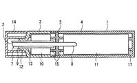
図1に示すマーキングペンは、第1バレル3と第2バレル4からなる軸筒本体、インキ誘導芯2、及び隔壁を形成する中間リング5を有している。第1バレル3にはインキ誘導芯保持部12と第1インキ貯蔵部10が設けられている。また、第2バレル4には第2インキ貯蔵部11が設けられている。
インキの貯蔵部は、第1バレル内の第1インキ貯蔵部10と第2バレル内の第2インキ貯蔵部11の2段に分離して設けられ、それぞれ異なる色のインキが貯蔵されている。第1バレル内の第1インキ貯蔵部10と第2バレル内の第2インキ貯蔵部11は、隔壁を形成する中間リング5により直接接触しないようにされている。インキ誘導芯2は、ペン先先端部近傍から第1インキ貯蔵部10を貫通する部分が内側芯8と外側芯7とに仕切り9で仕切られた二重構造で、更にその内側芯8のみが第2インキ貯蔵部に延長して挿入されている。かかる構造とすることにより、内側芯8には第2インキ貯蔵部11からインキが供給され、外側芯7には第1インキ貯蔵部10からインキが供給される。
このような構造のマーキングペンは、第2インキ貯蔵部のインキの筆跡を中心線として第1インキ貯蔵部のインキで縁取りされた多色の筆記線等を連続的に描くことが可能になる。
The marking pen shown in FIG. 1 has a shaft cylinder body composed of a first barrel 3 and a
The ink storage unit is provided separately in two stages, a first
The marking pen having such a structure can continuously draw multicolored writing lines and the like bordered with the ink of the first ink storage unit with the ink handwriting of the second ink storage unit as the center line.
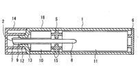
図4に示すマーキングペンは、インキ誘導芯保持部12、第1インキ貯蔵部10、及び第2インキ貯蔵部11が設けられた軸筒本体18、インキ誘導芯2、隔壁を形成する中間リング5、並びに尾栓6を有している。
インキの貯蔵部は、図1におけると同様に軸筒本体18内の第1インキ貯蔵部10と第2バレル内の第2インキ貯蔵部11の2段に分離して設けられ、それぞれ異なる色のインキが貯蔵され、第1インキ貯蔵部10と第2インキ貯蔵部11は、中間リング5により直接接触しないようにされている。インキ誘導芯2は、図1と同様に一部が二重構造になっている。かかる構造とすることにより、図1における場合と同様に内側芯8には第2インキ貯蔵部11からインキが供給され、外側芯7には第1インキ貯蔵部10からインキが供給される。このような構造のマーキングペンは、第2インキ貯蔵部のインキを中心線として第1インキ貯蔵部のインキで縁取りされた多色の筆記線等を連続的に描くことが可能になる。
以下に本発明のマーキングペンの各構成部について説明する。
The marking pen shown in FIG. 4 includes a
As in FIG. 1, the ink storage part is provided in two stages, a first
Hereinafter, each component of the marking pen of the present invention will be described.
(1)インキ誘導芯
本発明のインキ誘導芯は、軸筒本体の先端から一部突出して設けられたペン先を有していて、かつその一部が内側芯と外側芯に仕切られた二重構造を有している。
インキ誘導芯のペン先先端形状はチゼル型であり、ペン先先端部近傍から第1インキ貯蔵部を貫通する部分が内側芯と外側芯とに仕切られた二重構造であり、該二重構造部分においては、内側芯のインキと外側芯のインキがそれぞれ仕切りを通過できない構造となっている。また、更にその内側芯のみが第2インキ貯蔵部に延長して挿入されている。
従って、その外側芯は第1インキ貯蔵部からインキを供給され、内側芯は第2インキ貯蔵部からインキを供給されることになる。
インキ誘導芯の先端部を除く外観形状は、円柱状でも多角柱状でも特に制限はないが、その内側芯の作成、及び内側芯と外側芯との仕切りの加工等を考慮すると、内側芯は円柱形状が望ましい。
(1) Ink guide core The ink guide core of the present invention has a pen tip that is provided so as to partially protrude from the tip of the shaft cylinder body, and a part of which is divided into an inner core and an outer core. Has a heavy structure.
The tip shape of the nib tip of the ink guide core is a chisel type, and a double structure in which a portion penetrating the first ink storage part from the vicinity of the tip of the nib tip is divided into an inner core and an outer core, and the double structure In the portion, the inner core ink and the outer core ink cannot pass through the partition. Further, only the inner core is extended and inserted into the second ink storage section.
Therefore, the outer core is supplied with ink from the first ink storage section, and the inner core is supplied with ink from the second ink storage section.
The outer shape of the ink guide core excluding the tip of the ink guide core is not particularly limited, either cylindrical or polygonal, but considering the creation of the inner core and the processing of the partition between the inner core and the outer core, the inner core is a cylinder. Shape is desirable.
インキ誘導芯は、そのペン先先端形状がチゼル型である。該チゼル型とは一般的に溝を掘る工具であるのみの先端形状をいうが、本発明におけるチゼル型は、インキ誘導芯先端部の相対する面が両面側から先端に向かってテーパー状に先細りになっている形状とするのが好ましい。
チゼル型ペン先の先端面(筆記する面)は、長手方向に内側芯の両端部に外側芯が配置されている構造とすることが望ましい。かかる構造とすることにより、一回の線引きによりインキ誘導芯の内側芯による色彩を外側芯による色彩で帯状に縁取りされた筆跡を描くことが可能となる。また、前記内側芯の両端部に外側芯が配置されている構造における一端部の外側芯を欠落させた構造である、チゼル型ペン先の先端面が内側芯の一端に外側芯が配置されている構造とすることも可能である。かかる構造とすることにより、1回の線引きによりインキ誘導芯の内側芯による色彩と外側芯による色彩で帯状に2色の筆跡を描くことが可能となる。
The ink guide core has a chisel tip shape at the tip of the nib. The chisel type generally refers to a tip shape that is only a tool for digging a groove. However, the chisel type in the present invention is such that the opposite surfaces of the tip portion of the ink guide core taper from both sides toward the tip. It is preferable to have a shape.
It is desirable that the tip surface (the surface to be written) of the chisel-type nib has a structure in which outer cores are arranged at both ends of the inner core in the longitudinal direction. With such a structure, it is possible to draw a handwriting in which the color of the inner core of the ink guide core is bordered with the color of the outer core by one line drawing. The tip of the chisel-type nib is arranged at one end of the inner core, and the outer core is disposed at one end of the inner core. It is also possible to have a structure. With such a structure, it is possible to draw handwriting of two colors in a strip shape with a color by the inner core of the ink guide core and a color by the outer core by one line drawing.
ペン先先端の長手方向の幅は特に制限はないが、2〜8mm程度が好ましい。
ペン先先端は、図1のペン先に示されているようにその先端側を斜めに研削して、先端傾斜面とすることができる。例えば、先端傾斜面は先端側を軸径方向に対する傾斜角度を好ましくは0〜40度、特に好ましくは30〜35度とすることができる。また、ペン先先端は図4に示すペン先先端のように、外側を面取りすることもできる。この面取りされる外側芯の先端面の幅は、特に制限はないが0.2以上2mm未満とすることができる。
内側芯と外側芯から形成される二重構造部分における仕切りは、内側芯のインキが外側芯側へ、また外側芯側のインキが内側芯側へ通過しない構造であれば特に限定されるものではないが、使用するインキが水溶性インキまたは油溶性インキの場合、これらのインキに使用する溶剤に対し、耐溶剤性を有するものであることが好ましい。
仕切りとして、例えば内側芯と外側芯とを合成樹脂製のフィルムを使用することが可能であり、かかる合成樹脂製フィルムとしては、加工性等を考慮するとポリアセタール樹脂、アクリル樹脂、ポリエチレンテレフタレート樹脂、ポリプロピレン樹脂から選ばれる樹脂フィルムを例示することができる。
The width of the tip of the pen tip in the longitudinal direction is not particularly limited, but is preferably about 2 to 8 mm.
As shown in the pen tip of FIG. 1, the tip of the pen tip can be slanted on the tip side to form a tip inclined surface. For example, the inclined surface of the tip can be inclined at an angle of 0 to 40 degrees, particularly preferably 30 to 35 degrees with respect to the axial direction on the tip side. Further, the tip of the pen tip can be chamfered on the outside like the tip of the pen tip shown in FIG. The width of the end face of the outer core to be chamfered is not particularly limited, but can be 0.2 or more and less than 2 mm.
The partition in the double structure part formed from the inner core and the outer core is not particularly limited as long as the inner core ink does not pass to the outer core side and the outer core side ink does not pass to the inner core side. However, when the ink to be used is a water-soluble ink or an oil-soluble ink, it is preferable that the ink has solvent resistance with respect to the solvent used in these inks.
As the partition, for example, it is possible to use a film made of a synthetic resin with an inner core and an outer core, and as such a synthetic resin film, polyacetal resin, acrylic resin, polyethylene terephthalate resin, polypropylene are considered in consideration of processability and the like. A resin film selected from resins can be exemplified.
該仕切りに使用するフィルムの厚みは、0.05〜0.30mmが好ましく、0.05〜0.15mmが特に好ましい。また、内側芯を囲む形状の外側芯の厚みは、特に制限はなく、目的とする縁取り筆跡により任意に選択することが可能であるがペン先先端において0.2〜2mm程度とすることが好ましい。外側芯の厚みがこの範囲を超える場合には、ペン先をテーパー状に削り、前記厚みにすることもできる。
尚、水溶性インキと油溶性インキのそれぞれに個々に耐溶剤性を有するポリエステル系繊維、ポリアミド系繊維等からなるインキ誘導芯であっても、水溶性インキと油溶性インキの混合液に浸漬すると耐溶剤性が著しく低下する場合があるので、上記仕切りを設けることにより、このような不都合を回避することができる。
インキ誘導芯は、内側芯及び外側芯共に多数の繊維状物を収束して自己融着もしくは接着剤により部分的に接着して一体化し、その網目状空隙をインキ流路として形成する繊維体であることが望ましく、公知のインキ誘導芯も使用できる。例えば、特公昭53−16736号公報に開示されている繊維束ペン先の製造方法により作製することができる。前記繊維状物としては、ポリエステル系繊維、又はポリアミド系繊維の使用が好ましい。
The thickness of the film used for the partition is preferably 0.05 to 0.30 mm, particularly preferably 0.05 to 0.15 mm. Further, the thickness of the outer core having a shape surrounding the inner core is not particularly limited and can be arbitrarily selected depending on the intended edge handwriting, but is preferably about 0.2 to 2 mm at the tip of the pen tip. . When the thickness of the outer core exceeds this range, the pen tip can be cut into a taper shape to obtain the thickness.
It should be noted that even if the ink-derived core is made of polyester fiber, polyamide fiber, etc. each having solvent resistance in each of the water-soluble ink and the oil-soluble ink, if it is immersed in a mixture of water-soluble ink and oil-soluble ink Since the solvent resistance may be significantly reduced, such inconvenience can be avoided by providing the partition.
The ink guide core is a fibrous body that converges a large number of fibrous materials on both the inner core and the outer core, and partially adheres and integrates them by self-fusion or an adhesive, and forms a mesh-like void as an ink flow path. It is desirable that known ink guide cores can be used. For example, it can be produced by a method for producing a fiber bundle nib disclosed in Japanese Patent Publication No. 53-16736. As the fibrous material, it is preferable to use a polyester fiber or a polyamide fiber.
(2)軸筒本体
軸筒本体は、図1に示すように第1バレル3と第2バレル4とに分離した構造とすることが可能であり、また図4に示すように一体構造18とすることも可能である。
軸筒本体の主な機能は、インキ誘導芯の保持と、インキの貯蔵である。
軸筒本体内には、異なる色のインキが第1インキ貯蔵部10と第2インキ貯蔵部11に互いに接触しないように、二段に分けてそれぞれ貯蔵されている。尚、第1インキ貯蔵部10と第2インキ貯蔵部11との直接の接触を避けるために、これらの間に隔壁を設けるのが望ましい。このような隔壁は軸筒本体形状の一部として設けることもできるが、また図1又は図4に示すように、軸筒本体とは独立した構造である中間リングとすることも可能である。
軸筒本体を一体構造18とするか、2つのバレル3、4からなる分離した構造とするかにより、インキ貯蔵体等の挿入方法が異なってくる。
図1に示すように軸筒本体が2つのバレル3、4からなる構造の場合には、例えば、これらのバレルを分離した状態で第1バレル3にインキ誘導芯2と第1インキ貯蔵部10を挿入し、第2バレル4に第2インキ貯蔵部11と中間リング5を挿入した後に、第1バレル3に第2バレル4をはめ込む。尚、インキ誘導芯2は、第1バレル3に第2バレル4をはめ込む前後でも挿入することは可能である。
また、図4に示す軸筒本体が一体型18の場合には、尾栓側の開口部から第1インキ貯蔵部10、中間リング5、第2インキ貯蔵部11の順に軸筒本体に挿入すればよい。尚、インキ誘導芯のはめ込みは第1インキ貯蔵部10の挿入前でもよく、第2インキ貯蔵部11を挿入した後でも可能である。
(2) Shaft cylinder body The shaft cylinder body can be separated into the first barrel 3 and the
The main functions of the shaft cylinder main body are holding the ink guide core and storing ink.
In the shaft cylinder main body, different color inks are stored in two stages so as not to contact the first
The method of inserting the ink reservoir or the like differs depending on whether the shaft cylinder main body has an integrated
As shown in FIG. 1, in the case where the shaft cylinder body is composed of two
When the shaft cylinder main body shown in FIG. 4 is an
インキ誘導芯の内側芯8は第2インキ貯蔵部11内に少なくとも3mm以上、好ましくは5mm以上挿入するのが望ましい。
軸筒本体に設けられたインキ誘導芯保持部12におけるインキ誘導芯の位置決めは、図4に示すようにインキ誘導芯保持部12に段差構造を設けることができ、図1においてはインキ誘導芯保持部12又は中間リング5にテーパー形状部分を設けてインキ誘導芯を保持することができる。
尚、中間リング5の位置決めをするために、図1におけるように第2バレル4に溝を設けたり、図4に示すように軸筒本体の第1インキ貯蔵部10側に段差を設ける構造とすることができる。第1バレル3と第2バレル4との接続は、特に制限はないがはめ込み構造又はネジ構造により一体化される構成とすることができる。
本発明で使用する軸筒本体の外観形状は、特に制限を受けるものではなく公知のマーキングペンの外観形状でもよく、またその材料も特に制限を受けるものではなく公知のものを使用することができる。
It is desirable to insert the inner core 8 of the ink guide core into the second
The positioning of the ink guide core in the ink
In order to position the
The external shape of the shaft cylinder body used in the present invention is not particularly limited, and may be the external shape of a known marking pen, and the material is not particularly limited, and a known one can be used. .
(2−1)中間リング
本発明の軸筒本体内には、第1インキ貯蔵部と第2インキ貯蔵部との接触を避けるために、図1又は図4に示すような中間リング5を設けることができる。
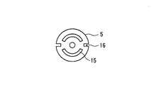
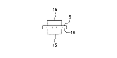
図1に示す中間リング5の具体例を図2と図3に示す。中間リング5には第1インキ貯蔵部10と第2インキ貯蔵部11に向けて突起15を設けて、これらのインキの接触を防止することができる。また、中間リング5には通気孔16を設けて第1バレル3内と第2バレル4内の圧力を均一に保つことが望ましい。図4に示す中間リング5の場合には例えば、図1と同様の突起を設けて、インキ誘導芯の内側芯が貫通する部分の孔径を大きくして、通気孔とすることができる。
(2−2)尾栓
図4に示す態様のように軸筒本体が一体構造18の場合には、第1インキ貯蔵部10、第2インキ貯蔵部11、及び中間リング5を挿入するために、ペン先側と相対する端部に開口部を設ける必要がある。該開口部は、前記第1インキ貯蔵部10等を挿入後尾栓6がはめ込まれる。
(2−3)キャップ
マーキングペンは、不使用時にインキ誘導芯からインキの溶剤等が蒸発するのを防止するためにキャップ14をはめ込んでおくことが望ましい。該キャップの形状は特に制限はなく、公知のものも使用可能である。図1と図4にキャップの具体例を示す。
(2-1) Intermediate ring In the shaft cylinder body of the present invention, an
Specific examples of the
(2-2) Tail plug In order to insert the first
(2-3) Cap It is desirable that the marking pen is fitted with the
(3)インキ貯蔵部
本発明において、インキ貯蔵部は、第1インキ貯蔵部と、第2インキ貯蔵部の2段に分離して設けられる。インキ貯蔵部におけるインキ貯蔵は、第1インキ貯蔵部と第2インキ貯蔵部においてインキ吸蔵体方式が好ましい。
インキ吸蔵体方式を用いる場合には、軸筒本体に第1インキ貯蔵部と及び第2インキ貯蔵部を挿入する前にインキを吸蔵させるか、又はこれらのインキ貯蔵部を軸筒本体に挿入後にインキを吸蔵させてもよい。インキ吸蔵体方式は、例えば、公知のポリエチレンテレフタレート、ポリアクリロニトリル、ポリプロピレン等の繊維をフィルム巻き、コーティング、自己溶着、硬化剤固定、繊維絡み合い等の方式でインキ吸蔵体を形成して、後述するインキ貯蔵容器内等に装着し、インキをこれらの吸蔵体に吸蔵させる方式である。
尚、インキ貯蔵容器部は、例えば、特公昭50−37571号公報に開示されているような公知の方法により作製することができる。
インキ貯蔵部は、その外側円周部を熱可塑性樹脂、例えばポリエチレン、ポリプロピレン等のシート・フィルムで作製したインキ貯蔵容器で覆うことができる。
インキ貯蔵部に貯蔵するインキは、油溶性インキと水溶性インキのいずれも使用が可能である。前記水溶性染料としては、酸性染料、塩基性染料、直接染料等を例示することができる。第1インキ貯蔵部及び第2インキ貯蔵部に貯蔵されているインキとして共に水溶性インキを使用すると油溶性インキの場合と異なり、有機溶剤臭の問題を生じない。また、縁取りの色合等を考慮して、第1インキ貯蔵部と第2インキ貯蔵部に貯蔵されているインキの一方を水溶性インキとし他方を油性インキとすることも可能であり、また双方のインキを油溶性インキとすることも可能である。
第1インキ貯蔵部と第2インキ貯蔵部のそれぞれのインキの貯蔵量は、ペン先先端部の筆記線を描く紙等との内側芯と外側芯の接触面積の割合による消費量等によって適宜決めることができるが、一方のインキを使い切るときにほぼ同時期に他方のインキも使い切るような割合とするのが望ましい。
(3) Ink Storage Unit In the present invention, the ink storage unit is provided separately in two stages of a first ink storage unit and a second ink storage unit. Ink storage in the ink storage unit is preferably an ink storage system in the first ink storage unit and the second ink storage unit.
When using the ink occlusion body method, the ink is occluded before inserting the first ink storage part and the second ink storage part into the shaft cylinder body, or after these ink storage parts are inserted into the axis cylinder body. The ink may be occluded. The ink occlusion body method is, for example, a method of forming an ink occlusion body by a method such as film winding, coating, self-adhesion, fixing of a curing agent, fiber entanglement, etc., for fibers such as known polyethylene terephthalate, polyacrylonitrile, polypropylene, etc. It is a system that is installed in a storage container and the like, and the ink is occluded in these occlusion bodies.
The ink storage container part can be produced by a known method as disclosed in, for example, Japanese Patent Publication No. 50-37571.
The ink reservoir can be covered with an ink reservoir made of a sheet or film made of a thermoplastic resin such as polyethylene or polypropylene.
As the ink stored in the ink storage section, either oil-soluble ink or water-soluble ink can be used. Examples of the water-soluble dye include acid dyes, basic dyes, and direct dyes. When both water-soluble inks are used as inks stored in the first ink storage unit and the second ink storage unit, unlike the case of oil-soluble inks, the problem of organic solvent odor does not occur. In consideration of the color of the border, one of the inks stored in the first ink storage unit and the second ink storage unit can be water-soluble ink, and the other can be oil-based ink. It is also possible to make the ink oil-soluble ink.
The amount of ink stored in each of the first ink storage unit and the second ink storage unit is appropriately determined depending on the consumption amount by the ratio of the contact area between the inner core and the outer core with the paper or the like on which the writing line at the tip of the pen tip is drawn. However, it is desirable that the ratio be such that when one ink is used up, the other ink is used up almost at the same time.
上記した本発明のマーキングを用いると、1回の線引きにより内側芯で描かれる中央線を外側芯で描かれる色で安定的に縁取りされた帯状の筆記線又は、インキ誘導芯の内側芯による色彩と外側芯による色彩で帯状に2色の筆跡等を連続的に確実に描くことが可能である。 When the marking of the present invention is used, the center line drawn with the inner core by one drawing is a band-like writing line stably bordered with the color drawn with the outer core, or the color by the inner core of the ink guide core It is possible to draw two-color handwriting continuously in a strip shape with the color of the outer core.
次に本願発明のマーキングペンの具体的な使用例を以下に示す。
尚、本願発明のマーキングペンは、これらの態様に何ら限定されるものではない。
Next, specific examples of use of the marking pen of the present invention are shown below.
In addition, the marking pen of this invention is not limited to these aspects at all.
1.マーキングペンの作製
図1に示す構成のマーキングペンを作製した。各構成部の詳細は下記の通りである。
(1)第1インキ貯蔵部のインキ
青色の油溶性染料(保土ヶ谷化学(株)製、商品名:SPT Blue GLSH)0.90質量%、2−フェノキシエタノール87.1質量%、ベンジルアルコール12.0質量%からなる油溶性インキ液を調製した。
(2)第2インキ貯蔵部のインキ
黄色の水溶性染料(バイエル社製、商品名:pyranin)2質量%、蒸留水87.5質量%、プロピレングリコール10.0質量%、水酸化ナトリウム0.1質量%、ベンゾイソチアゾリン系防腐剤0.4質量%からなる水溶性インキ液を調製した。
(3)インキの貯蔵
インキ吸蔵体は、ポリエチレンテレフタレート繊維より作製されたものである。
第1インキ貯蔵部:油溶性インキ吸蔵体、長さ20mm×直径20mm、Filtrona Filter GmbH製
第2インキ貯蔵部:水溶性インキ吸蔵体、長さ67mm×直径20mm、Filtrona Filter GmbH製
前記油溶性インキ液0.9mlと水溶性インキ液7.5mlをそれぞれ第1インキ貯蔵部と第2インキ貯蔵部の吸蔵体に吸蔵させた。
1. Production of Marking Pen A marking pen having the configuration shown in FIG. 1 was produced. Details of each component are as follows.
(1) Ink in the first ink storage section Blue oil-soluble dye (Hodogaya Chemical Co., Ltd., trade name: SPT Blue GLSH) 0.90% by mass, 2-phenoxyethanol 87.1% by mass, benzyl alcohol 12.0% by mass A soluble ink solution was prepared.
(2) Ink in the second ink storage section Yellow water-soluble dye (manufactured by Bayer, trade name: pyranin) 2% by mass, distilled water 87.5% by mass, propylene glycol 10.0% by mass, sodium hydroxide 0.1% by mass, benzoisothiazoline A water-soluble ink solution comprising 0.4% by mass of a system preservative was prepared.
(3) Storage of ink The ink occlusion body is produced from polyethylene terephthalate fiber.
First ink reservoir: oil-soluble ink occlusion body, length 20 mm x diameter 20 mm, manufactured by Filtrona Filter GmbH Second ink reservoir: water-soluble ink occlusion body, length 67 mm x diameter 20 mm, made by Filtrona Filter GmbH The oil-soluble ink 0.9 ml of the liquid and 7.5 ml of the water-soluble ink liquid were occluded in the occlusion bodies of the first ink reservoir and the second ink reservoir, respectively.
(4)インキ誘導芯
使用したインキ誘導芯のチゼル型ペン先幅は7mmであり、インキ誘導芯は、ポリエチレンテレフタレート繊維体より作製されたものである(テイボウ販売(株)製)。
内側芯:円柱状、直径3.5mm、長さ67mm
外側芯:厚み1.75mm、長さ44mm
仕切りのフィルム:ポリアセタール製、厚み0.1mm、長さ43mm
2.筆記線
上記マーキングペンを使用して筆記線を描いた。黄色が帯状に青色ないし緑色で縁取りされた多色の筆記線を連続的に描くことができた。
(4) Ink induction core The chisel-type nib width of the ink induction core used was 7 mm, and the ink induction core was made from a polyethylene terephthalate fiber (manufactured by Teibo Sales Co., Ltd.).
Inner core: cylindrical, diameter 3.5mm, length 67mm
Outer core: thickness 1.75mm, length 44mm
Partition film: Polyacetal, thickness 0.1mm, length 43mm
2. Writing Line A writing line was drawn using the above marking pen. I was able to draw a multicolored writing line in which the yellow was banded in blue or green.
1.マーキングペンの作製
図1に示す構成のマーキングペンを作製した。各構成部の詳細は下記の通りである。
(1)第1インキ貯蔵部のインキ
桃色の蛍光分散顔料水溶性インキ(日本蛍光化学(株)製、商品名:ルミコールNKW3007)
(2)第2インキ貯蔵部のインキ
黄色の蛍光分散顔料水溶性インキ(日本蛍光化学(株)製、商品名:ルミコールNKW3005)
(3)インキの貯蔵
インキ吸蔵体はポリエチレンテレフタレート繊維より作製されたものである。
第1インキ貯蔵部:水溶性桃色インキ吸蔵体、長さ20mm×直径20mm、Filtrona Filter GmbH製
第2インキ貯蔵部:水溶性黄色インキ吸蔵体、長さ67mm×直径20mm、Filtrona Filter GmbH製
前記水溶性桃色インキ液0.9mlと水溶性黄色インキ液7.5mlをそれぞれ第1インキ貯蔵部と第2インキ貯蔵部の吸蔵体に吸蔵させた。
1. Production of Marking Pen A marking pen having the configuration shown in FIG. 1 was produced. Details of each component are as follows.
(1) Ink in the first ink storage unit Pink fluorescent dispersion pigment water-soluble ink (manufactured by Nippon Fluorochemicals, Inc., trade name: Lumicol NKW3007)
(2) Ink of the second ink storage unit Yellow fluorescent dispersion pigment water-soluble ink (manufactured by Nippon Fluorochemicals, Inc., trade name: Lumicol NKW3005)
(3) Storage of ink The ink occlusion body is made from polyethylene terephthalate fiber.
First ink reservoir: water-soluble pink ink occlusion body, length 20 mm x diameter 20 mm, manufactured by Filtrona Filter GmbH Second ink reservoir: water-soluble yellow ink occlusion body, length 67 mm x diameter 20 mm, manufactured by Filtrona Filter GmbH 0.9 ml of a neutral pink ink liquid and 7.5 ml of a water-soluble yellow ink liquid were occluded in the occlusion bodies of the first ink reservoir and the second ink reservoir, respectively.
(4)インキ誘導芯
使用したインキ誘導芯のチゼル型ペン先幅は5mmであり、インキ誘導芯は、ポリエチレンテレフタレート繊維体より作製されたものである(テイボウ販売(株)製)。
内側芯:円柱状、直径3.5mm、長さ67mm
外側芯:厚み1.75mm(ペン先先端部の厚みが0.75mmとなるように先端部の両外側を面取りした)、長さ44mm
仕切りのフィルム:ポリアセタール製、厚み0.1mm、長さ43mm
2.筆記線
上記マーキングペンを使用して筆記線を描いた。黄色が細い帯状に桃色ないし橙色で縁取りされた多色の筆記線を連続的に描くことができた。
(4) Ink induction core The chisel-type nib width of the ink induction core used was 5 mm, and the ink induction core was made from a polyethylene terephthalate fiber (manufactured by Teibo Sales Co., Ltd.).
Inner core: cylindrical, diameter 3.5mm, length 67mm
Outer core: thickness 1.75 mm (both outer sides of the tip end are chamfered so that the thickness of the tip end of the pen tip is 0.75 mm), length 44 mm
Partition film: Polyacetal, thickness 0.1mm, length 43mm
2. Writing Line A writing line was drawn using the above marking pen. I was able to draw a continuous line of multicolored writing lines with a yellow or thin strip of pink or orange.
本発明のマーキングペンは広く筆記用具として使用可能である。 The marking pen of the present invention can be widely used as a writing instrument.
1 軸筒
2 インキ誘導芯
3 第1バレル
4 第2バレル
5 中間リング
6 尾栓
7 外側芯
8 内側芯
9 仕切り
10 第1インキ貯蔵部
11 第2インキ貯蔵部
12 インキ誘導芯保持部
13 突起
14 キャップ
15 突起
16 通気孔
17 突起
18 軸筒本体
DESCRIPTION OF SYMBOLS 1
Claims (17)
(i)第1インキ貯蔵部には第2インキ貯蔵部に貯蔵されているインキと異なる色のインキが貯蔵されており、(ii)該インキ誘導芯は、そのペン先先端形状がチゼル型で、ペン先先端部近傍から第1インキ貯蔵部を貫通する部分が内側芯と外側芯に仕切られた二重構造であって、更にその内側芯のみが第2インキ貯蔵部に延長して挿入されており、
(iii)外側芯は第1インキ貯蔵部からインキが供給され、内側芯は第2インキ貯蔵部からインキが供給される
ことを特徴とするマーキングペン。 An ink guide core composed of an inner core and an outer core, and a first ink storage section in which the ink storage section is located in the pen tip side area, and the other end. A marking pen having a shaft body provided separately in two stages in a second ink storage part located in a side region,
(I) The first ink storage unit stores ink of a different color from the ink stored in the second ink storage unit, and (ii) the ink guide core has a chisel tip shape. The portion penetrating the first ink reservoir from the vicinity of the tip of the nib is divided into an inner core and an outer core, and only the inner core is extended and inserted into the second ink reservoir. And
(Iii) A marking pen, wherein the outer core is supplied with ink from the first ink storage section, and the inner core is supplied with ink from the second ink storage section.
Priority Applications (1)
| Application Number | Priority Date | Filing Date | Title |
|---|---|---|---|
| JP2004119459A JP2005297450A (en) | 2004-04-14 | 2004-04-14 | Marking pen |
Applications Claiming Priority (1)
| Application Number | Priority Date | Filing Date | Title |
|---|---|---|---|
| JP2004119459A JP2005297450A (en) | 2004-04-14 | 2004-04-14 | Marking pen |
Publications (1)
| Publication Number | Publication Date |
|---|---|
| JP2005297450A true JP2005297450A (en) | 2005-10-27 |
Family
ID=35329575
Family Applications (1)
| Application Number | Title | Priority Date | Filing Date |
|---|---|---|---|
| JP2004119459A Withdrawn JP2005297450A (en) | 2004-04-14 | 2004-04-14 | Marking pen |
Country Status (1)
| Country | Link |
|---|---|
| JP (1) | JP2005297450A (en) |
-
2004
- 2004-04-14 JP JP2004119459A patent/JP2005297450A/en not_active Withdrawn
Similar Documents
| Publication | Publication Date | Title |
|---|---|---|
| KR100758391B1 (en) | Writing implements of double head type | |
| CN105050827B (en) | Pens and ink cartridges | |
| US5352051A (en) | Writing instrument | |
| US20040161282A1 (en) | Marker pens | |
| JP2019214216A (en) | Writing implement | |
| US20060165470A1 (en) | Connector systems and marker systems comprising same | |
| JP2004520205A5 (en) | ||
| WO2011158837A1 (en) | Writing instrument | |
| JP2005297450A (en) | Marking pen | |
| JP2005313404A (en) | Writing instrument | |
| US7083349B2 (en) | Writing implement | |
| WO2001015912A1 (en) | Multi-color marker | |
| JPH10309885A (en) | Direct liquid writing instrument | |
| JP5367486B2 (en) | Multi-core writing instrument | |
| JPH0331578Y2 (en) | ||
| JP2017124544A (en) | Writing instrument | |
| KR200339043Y1 (en) | Multi-Color Writing Instrument | |
| JP5340010B2 (en) | Writing instrument and method for manufacturing the same | |
| CN215970828U (en) | Double-head pen | |
| JPH10217671A (en) | Line marker | |
| CN217396068U (en) | Ink supply pen tongue and pen | |
| CN212604174U (en) | Dual-purpose fluorescent pen | |
| JP7224136B2 (en) | writing instrument | |
| JP7224137B2 (en) | writing instrument | |
| JP2005088251A (en) | Marking pen |
Legal Events
| Date | Code | Title | Description |
|---|---|---|---|
| A300 | Withdrawal of application because of no request for examination |
Free format text: JAPANESE INTERMEDIATE CODE: A300 Effective date: 20070703 |