JP2025041298A - Mold for injection molding, manufacturing method for resin molded product, and injection molding method - Google Patents

Mold for injection molding, manufacturing method for resin molded product, and injection molding method Download PDF

Info

Publication number
JP2025041298A
JP2025041298A JP2023148492A JP2023148492A JP2025041298A JP 2025041298 A JP2025041298 A JP 2025041298A JP 2023148492 A JP2023148492 A JP 2023148492A JP 2023148492 A JP2023148492 A JP 2023148492A JP 2025041298 A JP2025041298 A JP 2025041298A
Authority
JP
Japan
Prior art keywords
mold
fixed
plate
movable
resin
Prior art date
Legal status (The legal status is an assumption and is not a legal conclusion. Google has not performed a legal analysis and makes no representation as to the accuracy of the status listed.)
Pending
Application number
JP2023148492A
Other languages
Japanese (ja)
Inventor
憲生 多田
Norio Tada
隆晃 高橋
Takaaki Takahashi
Current Assignee (The listed assignees may be inaccurate. Google has not performed a legal analysis and makes no representation or warranty as to the accuracy of the list.)
Gifu Tadaseiki Co Ltd
Original Assignee
Gifu Tadaseiki Co Ltd
Priority date (The priority date is an assumption and is not a legal conclusion. Google has not performed a legal analysis and makes no representation as to the accuracy of the date listed.)
Filing date
Publication date
Application filed by Gifu Tadaseiki Co Ltd filed Critical Gifu Tadaseiki Co Ltd
Priority to JP2023148492A priority Critical patent/JP2025041298A/en
Publication of JP2025041298A publication Critical patent/JP2025041298A/en
Pending legal-status Critical Current

Links

Images

Landscapes

  • Moulds For Moulding Plastics Or The Like (AREA)

Abstract

To prevent burrs in injection molding of two-component thermosetting resins.SOLUTION: The mold 10A for in-mold coating molding comprises a fixed side mold 100A with a fixed side mold plate 13A, a movable side mold 200 with a movable side mold plate 23 opposite the fixed side mold plate, flow channels formed in the fixed side mold and/or the movable side mold and comprising sprues 111, 113, runners 112, and pin gates 114 through which the injected paint flow, and a cavity formed between the fixed side mold plate and the movable side mold plate by mold clamping of the fixed side mold and the movable side mold plate, in which a resin molded product 500B is placed and the paint is filled into the clearance formed between the resin molded product and the fixed side mold plate. The surface roughness Rz of a parting surface 300 between the fixed side mold plate and the movable side mold plate is 0.8 μm or less, preferably 0.6 μm or less, more preferably 0.4 μm or less, and even more preferably 0.2 μm or less.SELECTED DRAWING: Figure 11

Description

本発明は、2液混合型の熱硬化性樹脂の射出成形に使用される射出成形用金型、2液混合型の熱硬化性樹脂を用いた樹脂成形品の製造方法、及び2液混合型の熱硬化性樹脂の射出成形方法であって、特に、バリの発生を抑制できる射出成形用金型、樹脂成形品の製造方法、及び射出成形方法に関するものである。ここで、「射出成形」は、高い圧力を加えて樹脂を金型に噴出することに限定されず、樹脂を金型に注入する概念を含むものであり、金型に樹脂を充填(射出、注入)して成形する広義の意味で捉えられるものである。 The present invention relates to an injection molding die used for injection molding of a two-component mixed type thermosetting resin, a manufacturing method for a resin molded product using a two-component mixed type thermosetting resin, and a method for injection molding of a two-component mixed type thermosetting resin, and in particular to an injection molding die, a manufacturing method for a resin molded product, and an injection molding method that can suppress the occurrence of burrs. Here, "injection molding" is not limited to spraying resin into a die by applying high pressure, but includes the concept of injecting resin into a die, and is understood in the broad sense of filling (injecting, pouring) resin into a die to mold it.

樹脂成形品の加飾技術として、樹脂成形品の表面に塗料や被覆剤を塗布する塗装法が知られている。従来の塗装法においては、金型内で成形した樹脂成形品を金型から取り出し、後工程で、スプレー法や浸漬法等により、その表面に塗料を塗布することが一般的であった。
これに対し、近年、省エネ化、低環境負荷を目的とした塗装工程の短縮化や、塗装コストの低減化の観点から、樹脂成形品を金型内で塗装する技術、即ち、金型内で射出成形した樹脂成形品の成型後に、同一金型内でまたは射出成形装置の成形サイクル内で樹脂成形品の表面と金型のキャビティ面との間に塗料を注入し、塗料を金型内で硬化させて樹脂成形品と一体化する金型内塗装方法(インモールドコーティング法ともいう)の技術が知られている。
A painting method in which paint or a coating agent is applied to the surface of a resin molded product is known as a decorative technique for resin molded products. In conventional painting methods, a resin molded product is generally molded in a mold, and then removed from the mold, and paint is applied to the surface in a post-process by a spray method, a dipping method, or the like.
In response to this, in recent years, from the viewpoint of shortening the painting process for the purposes of saving energy and reducing the environmental load, and reducing painting costs, a technique for painting a resin molded product inside a mold has become known. In other words, after the resin molded product is injection-molded in a mold, paint is injected between the surface of the resin molded product and the cavity surface of the mold, either within the same mold or within the molding cycle of the injection molding device, and the paint is cured inside the mold to become integrated with the resin molded product. This is called an in-mold coating method.

ところが、通常の射出成形における熱可塑性樹脂の溶融樹脂と比較し、樹脂成形品の加飾用に使用される2液混合型の熱硬化性樹脂の塗料粘度は非常に低いものである。そのため、型内塗装においては、固定側金型及び可動側金型間のパーティング面のわずかな隙間に塗料が漏出してそこで硬化することにより塗装樹脂成形品の周端にバリが発生しやく、成形品の歩留まりが悪くなったり、塗装後に余分なバリ取り作業を要することで、生産性が低くなったりする問題がある。特に、塗料がパーティング面に漏出しそこで硬化すると、それが金型を傷付けたり、次サイクルの成形品に付着したり、型締めに負荷を掛けたりする恐れがあるため、漏出して固化した塗料は除去しなければならず、成形サイクルが長くなり連続成形の生産性を低下させることになる。 However, compared to the molten thermoplastic resin used in normal injection molding, the paint viscosity of the two-liquid mixed thermosetting resin used to decorate resin molded products is very low. Therefore, in-mold painting, paint leaks into the small gap on the parting surface between the fixed mold and the movable mold and hardens there, which can easily cause burrs to form on the peripheral edges of the painted resin molded product, resulting in problems such as poor yield of molded products and reduced productivity due to the need for extra deburring work after painting. In particular, if paint leaks onto the parting surface and hardens there, it may damage the mold, adhere to the molded product in the next cycle, or put a strain on the mold clamping, so the leaked and solidified paint must be removed, which lengthens the molding cycle and reduces the productivity of continuous molding.

また、近年、例えば、環境負荷軽減への対応やコスト削減等の観点から、各種機械、装置、部品等の小型化、軽量化、薄型化が進んでおり、これに伴い成形品の薄肉化、小型化や、複雑な形状の成形品等が要求されている。
ここで、複雑な形状の成形品や精密な成形品等の製造にあっては、射出成形が好ましく用いられるが、射出成形で一般的に用いられている熱可塑性樹脂のペレットを溶融して射出成形する場合には、溶融樹脂材料の流動性が悪く薄肉形状等に対応するキャビティ内の隅々まで確実に均一に溶融樹脂を充填することが難しいことから、ヒケ等の成形不良を生じやすく、薄肉や複雑な形状とする高精密成形に対応することが困難であった。そこで、薄肉や複雑な形状の成形品等を射出成形法により得る場合には、流動性の良好な樹脂を用いる必要が生じる。
例えば、特許文献1では、樹脂のペレット化工程を必要としない2液混合射出成形により、軟質ポリウレタン成型体を製造する技術が開示されている。
ところが、特許文献1のように2液混合物を高温の金型に射出する場合にも、その金型内での成形時にキャビティ外に樹脂が漏れてバリが発生しやすいという問題がある。
Furthermore, in recent years, for example, from the standpoint of reducing the environmental load and cutting costs, various machines, devices, parts, etc. have been made smaller, lighter, and thinner. As a result, there is a demand for thinner, smaller molded products and molded products with complex shapes.
Here, injection molding is preferably used for manufacturing molded products of complex shapes or precision molded products, but when injection molding is performed by melting pellets of thermoplastic resin, which is generally used in injection molding, the fluidity of the molten resin material is poor, making it difficult to reliably and uniformly fill every corner of a cavity corresponding to a thin-walled shape, etc., with the molten resin, which is prone to molding defects such as sink marks, making it difficult to handle high-precision molding of thin walls or complex shapes. Therefore, when obtaining molded products of thin walls or complex shapes by injection molding, it becomes necessary to use a resin with good fluidity.
For example, Patent Document 1 discloses a technique for producing a soft polyurethane molded article by two-liquid mixing injection molding, which does not require a resin pelletizing process.
However, even when a two-liquid mixture is injected into a high-temperature mold as in Patent Document 1, there is a problem in that the resin is likely to leak outside the cavity during molding in the mold, resulting in the generation of burrs.

ここで、例えば、特許文献2では、裏面形成金型と表面形成金型と塗膜形成金型とを備える型内塗装品形成用金型を用い、裏面形成金型と表面形成金型とを型閉じして、成形品を形成するための成形キャビティを裏面形成金型と表面形成金型との間に形成し、成形キャビティ内に成形樹脂を充填し冷却固化させて成形品を形成し、裏面形成金型が成形品を保持する状態で裏面形成金型と表面形成金型とを型開きし、裏面形成金型と対向する表面形成金型を塗膜形成金型に切り替え、成形品を保持する裏面形成金型と塗膜形成金型とを型閉じして、成形品を熱硬化性塗料で塗装するための塗装キャビティを成形品と塗膜形成金型との間に形成し、塗装キャビティ内に熱硬化性塗料を注入して固化させることによって、成形品に熱硬化性塗料層を一体被覆させることにより、金型の分割面がシェアエッジ構造ではない一般的なフラットな面であっても、樹脂や熱硬化性塗料が金型キャビティから漏れ出すことを防止できる技術を開示している。 For example, Patent Document 2 discloses a technique in which a mold for forming an in-mold coated product is used, the mold for forming the in-mold coated product includes a back surface forming mold, a front surface forming mold, and a coating film forming mold, the back surface forming mold and the front surface forming mold are closed to form a molding cavity for forming a molded product between the back surface forming mold and the front surface forming mold, molding resin is filled into the molding cavity and cooled and solidified to form a molded product, the back surface forming mold and the front surface forming mold are opened while the back surface forming mold holds the molded product, the front surface forming mold facing the back surface forming mold are switched to a coating film forming mold, the back surface forming mold and the coating film forming mold holding the molded product are closed to form a coating cavity between the molded product and the coating film forming mold, and the thermosetting paint is injected into the coating cavity and solidified to integrally coat the molded product with a thermosetting paint layer, thereby preventing the resin or thermosetting paint from leaking out of the mold cavity, even if the parting surface of the mold is a general flat surface that does not have a share edge structure.

特開2010-215820号公報JP 2010-215820 A 特開2009-101670号公報JP 2009-101670 A

しかしながら、特許文献2の技術においては、熱硬化性塗料の外部への漏れを防ぐシール圧力に関して、型締め力、型内圧、製品寸法、偏芯等の影響を受けるために不確実でその効果が限定的なものとなる可能性がある。 However, in the technology of Patent Document 2, the sealing pressure that prevents the thermosetting paint from leaking to the outside is affected by the mold clamping force, mold internal pressure, product dimensions, eccentricity, etc., so it is uncertain and its effectiveness may be limited.

そこで、本発明は、2液混合型の熱硬化性樹脂の射出成形においてバリの発生を抑制できる射出成形用金型、樹脂成形品の製造方法、及び射出成形方法の提供を課題とするものである。 The present invention aims to provide an injection molding die, a manufacturing method for resin molded products, and an injection molding method that can suppress the generation of burrs during injection molding of two-liquid mixed thermosetting resins.

請求項1の発明の射出成形用金型は、2液混合型の熱硬化性樹脂を成形する射出成形用金型であって、固定側型板を備えた固定側金型と、前記固定側型板に対向する可動側型板を備えた可動側金型と、前記固定側金型及び/または前記可動側金型に形成され、射出注入された前記2液混合型の熱硬化性樹脂が流れる流路と、前記固定側金型と前記可動側金型の型締めによって前記固定側型板と前記可動側型板の間に形成され、前記流路を通った前記2液混合型の熱硬化性樹脂が流入されるキャビティとを具備し、前記固定側型板及び前記可動側型板の間のパーティング面の表面粗さRzを0.8μm以下、好ましくは、0.6μm以下、より好ましくは、0.4μm以下、更に好ましくは、0.2μm以下としたものである。 The injection mold of the invention of claim 1 is an injection mold for molding a two-component mixed thermosetting resin, and is provided with a fixed-side mold having a fixed-side mold plate, a movable-side mold having a movable-side mold plate facing the fixed-side mold plate, a flow path formed in the fixed-side mold and/or the movable-side mold through which the injected two-component mixed thermosetting resin flows, and a cavity formed between the fixed-side mold plate and the movable-side mold plate by clamping the fixed-side mold and the movable-side mold, into which the two-component mixed thermosetting resin flows after passing through the flow path, and the surface roughness Rz of the parting surface between the fixed-side mold plate and the movable-side mold plate is 0.8 μm or less, preferably 0.6 μm or less, more preferably 0.4 μm or less, and even more preferably 0.2 μm or less.

上記固定側金型は、キャビティ内で形成する樹脂成形品の一方面側に対応する固定側型板を備え、樹脂の注入機のノズルから射出注入される2液混合型の熱硬化性樹脂を通す流路を設けたものである。
また、上記可動側金型は、固定側金型に対向して配置され、射出成形用金型において開閉の往復運動をする側であり、固定側型板側とは反対側で樹脂成形品の他方面側に対応する可動側型板を備えているものである。
The fixed side mold is equipped with a fixed side plate corresponding to one side of the resin molded product to be formed in the cavity, and is provided with a flow path through which a two-component mixed thermosetting resin that is injected from the nozzle of a resin injection machine passes.
In addition, the movable side mold is positioned opposite the fixed side mold and is the side that reciprocates between opening and closing in the injection molding mold, and is equipped with a movable side mold plate that is on the opposite side to the fixed side mold plate and corresponds to the other side of the resin molded product.

上記パーティング面(PL面)は、固定側型板と可動側型板の対向面となる分割面、即ち、型締めで固定側型板と可動側型板が当接する合わせ面であり、その表面粗さRzを0.8μm以下、好ましくは、0.6μm以下、より好ましくは、0.4μm以下、更に好ましくは、0.2μm以下としたものである。なお、表面処理技術からして、その下限値は、0.05μmである。 The parting surface (PL surface) is the dividing surface that is the opposing surface of the fixed side mold plate and the movable side mold plate, i.e., the mating surface where the fixed side mold plate and the movable side mold plate come into contact when the mold is clamped, and has a surface roughness Rz of 0.8 μm or less, preferably 0.6 μm or less, more preferably 0.4 μm or less, and even more preferably 0.2 μm or less. In terms of surface treatment technology, the lower limit is 0.05 μm.

また、請求項2の発明の射出成形用金型の前記流路は、ピンゲートを有するものである。
上記ピンゲート(ピンポイントゲートとも云う)は、射出注入された2液混合型の熱硬化性樹脂が通る通路のうち、キャビティに樹脂を注入する最小径(最細径)の部分であり、型開き時に、キャビティ内で形成された樹脂成形品と、スプルー、ランナー、及びピンゲート内で樹脂が熱硬化したスプルー・ランナー側樹脂とを切り離せる構成とするためのものである。
In the injection molding die of the present invention, the flow passage has a pin gate.
The pin gate (also called a pinpoint gate) is the part of the passage through which the two-component mixed thermosetting resin passes that has the smallest diameter (narrowest diameter) for injecting the resin into the cavity, and is intended to enable the resin molded product formed in the cavity to be separated from the sprue, runner, and sprue/runner side resin that has thermoset within the pin gate when the mold is opened.

請求項3の発明の射出成形用金型の前記流路は、前記2液混合型の熱硬化性樹脂が射出される軸方向に延びた1次スプルー、前記1次スプルーに連続し前記1次スプルーの略直角方向に形成されたランナー、前記ランナーに連続し前記1次スプルーと並行方向に延びた2次スプルー、及び前記2次スプルーと前記キャビティとを連通したピンゲートから形成されているものである。 The flow path of the injection molding die of the invention of claim 3 is formed from a primary sprue extending in the axial direction into which the two-component mixed thermosetting resin is injected, a runner continuing from the primary sprue and formed in a direction approximately perpendicular to the primary sprue, a secondary sprue continuing from the runner and extending in a direction parallel to the primary sprue, and a pin gate connecting the secondary sprue to the cavity.

上記1次スプルー(縦ランナーと呼ばれることもある)は、金型に射出注入された樹脂が金型内で最初に流れ込まれ、当該樹脂をランナーに送り込む流路であり、樹脂の注入機の軸方向と同軸方向に設けられるものである。
上記ランナーは、1次スプルーに連続し、一般的には、樹脂の射出軸方向に対して略直角方向に分岐して設けられるものである。
上記2次スプルー(縦ランナーと呼ばれることもある)は、ランナーに連続し、樹脂の射出軸方向と並行に設けられるものである。
上記ピンゲート(ピンポイントゲートとも云う)は、2次スプルーの流路をキャビティに繋ぐ通路であり、射出注入された樹脂が通る通路のうち、キャビティに樹脂を注入する最小径(最細径)の部分であり、型開き時に、キャビティ内で形成された樹脂成形品と、スプルー、ランナー、及びピンゲート内で形成されたスプルー・ランナー樹脂とを切り離せる構成とするためのものである。
The primary sprue (sometimes called a vertical runner) is the flow path through which the resin injected into the mold first flows into the mold and sends the resin to the runner, and is arranged in the same axial direction as the resin injection machine.
The runner is continuous with the primary sprue, and is generally provided branching out in a direction approximately perpendicular to the direction of the resin injection axis.
The secondary sprue (sometimes called a vertical runner) is continuous with the runner and is provided parallel to the direction of the injection axis of the resin.
The pin gate (also called a pinpoint gate) is a passage that connects the flow path of the secondary sprue to the cavity, and is the part of the passage through which the injected resin passes that has the smallest diameter (narrowest diameter) for injecting the resin into the cavity. It is designed to enable the resin molded product formed in the cavity to be separated from the sprue, runner, and sprue/runner resin formed in the pin gate when the mold is opened.

請求項4の発明の射出成形用金型は、前記固定側金型において、前記固定側型板の前記キャビティ形成側とは反対面側でランナーストリッパープレートが設けられ、また、前記ランナーストリッパープレートの前記固定側型板側とは反対面側に固定側取付板が設けられており、前記固定側金型と前記可動型金型の型開きの際に、前記可動側型板及び前記固定側型板の間、並びに、前記固定側型板及び前記ランナーストリッパープレートの間を開くことで、前記キャビティで前記2液混合型の熱硬化性樹脂が熱硬化して形成された樹脂成形品と、前記固定側金型の前記スプルー、ランナー、及びピンゲートからなる前記流路で前記2液混合型の熱硬化性樹脂が熱硬化して形成されたスプルー・ランナー樹脂とが分離するものである。 The injection molding die of the invention of claim 4 has a runner stripper plate on the fixed die opposite the cavity forming side of the fixed die plate, and a fixed attachment plate on the runner stripper plate opposite the fixed die plate. When the fixed die and the movable die are opened, the space between the movable die plate and the fixed die plate, and the space between the fixed die plate and the runner stripper plate are opened, so that a resin molded product formed by thermally curing the two-part mixed thermosetting resin in the cavity is separated from a sprue/runner resin formed by thermally curing the two-part mixed thermosetting resin in the flow path consisting of the sprue, runner, and pin gate of the fixed die.

上記固定側取付板は、射出成形装置の固定盤にボルト等で取付けるためのものである。
上記ランナーストリッパープレートは、固定側取付板と固定側型板との間に配置され、金型の型開きによって、固定側金型のスプルー、ランナー、及びピンゲートからなる流路で2液混合型の熱硬化性樹脂が熱硬化したスプルー・ランナー樹脂を、キャビティで2液混合型の熱硬化性樹脂が熱硬化した樹脂成形品と切り離すためのものである。
The fixed side mounting plate is for mounting to a fixed platen of an injection molding machine with bolts or the like.
The runner stripper plate is disposed between the fixed side mounting plate and the fixed side mold plate, and serves to separate the sprue/runner resin, which is a two-component mixed thermosetting resin heat-cured in the flow passage consisting of the sprue, runner, and pin gate of the fixed side mold, from the resin molded product, which is a two-component mixed thermosetting resin heat-cured in the cavity, when the mold is opened.

請求項5の発明の射出成形用金型の前記固定側金型の前記ランナーは、前記固定側型板及び前記ランナーストリッパープレートの間に形成され、前記固定側型板及び前記ランナーストリッパープレートの分割面の表面粗さRzが0.8μm以下、好ましくは、0.6μm以下、より好ましくは、0.4μm以下、更に好ましくは、0.2μm以下であるものである。
上記分割面は、固定側型板とランナーストリッパープレートの対向面であって、型締めで閉じられたときに固定側型板とランナーストリッパープレートが当接する合わせ面であり、その表面粗さRzを0.8μm以下、好ましくは、0.6μm以下、より好ましくは、0.4μm以下、更に好ましくは、0.2μm以下としたものである。なお、表面処理技術からして、その下限値は、0.05μmである。
The runner of the fixed side die of the injection molding die of the invention of claim 5 is formed between the fixed side mold plate and the runner stripper plate, and the surface roughness Rz of the parting surfaces of the fixed side mold plate and the runner stripper plate is 0.8 μm or less, preferably 0.6 μm or less, more preferably 0.4 μm or less, and even more preferably 0.2 μm or less.
The parting surface is the opposing surface of the fixed side mold plate and the runner stripper plate, which is a mating surface where the fixed side mold plate and the runner stripper plate come into contact when the molds are closed by clamping, and has a surface roughness Rz of 0.8 μm or less, preferably 0.6 μm or less, more preferably 0.4 μm or less, and further preferably 0.2 μm or less. From the viewpoint of surface treatment technology, the lower limit is 0.05 μm.

請求項6の発明の樹脂成形品の製造方法は、固定側型板を備えた固定側金型と可動側型板とを備えた可動側金型で構成され、前記固定側型板及び前記可動側型板の間のパーティング面の表面粗さRzが0.8μm以下、好ましくは、0.6μm以下、より好ましくは、0.4μm以下、更に好ましくは、0.2μm以下である射出成形用金型の前記固定側金型及び前記可動側金型を型締めし、前記可動側金型と前記固定側金型の間にキャビティを形成する型締め工程と、前記キャビティに向けて2液混合型の熱硬化性樹脂を射出注入する射出注入工程と、前記キャビティに充填された前記2液混合型の熱硬化性樹脂を成形する成形工程と、前記可動側金型及び前記固定側金型を型開きし、前記成形工程で形成された樹脂成形品を取り出す型開き工程とを具備するものである。 The manufacturing method of the resin molded product of the invention of claim 6 is comprised of a fixed side mold having a fixed side mold plate and a movable side mold having a movable side mold plate, and the surface roughness Rz of the parting surface between the fixed side mold plate and the movable side mold plate is 0.8 μm or less, preferably 0.6 μm or less, more preferably 0.4 μm or less, and even more preferably 0.2 μm or less. The manufacturing method of the resin molded product of the invention of claim 6 is comprised of a mold clamping process of clamping the fixed side mold and the movable side mold of an injection molding mold to form a cavity between the movable side mold and the fixed side mold, an injection injection process of injecting a two-part mixed thermosetting resin into the cavity, a molding process of molding the two-part mixed thermosetting resin filled in the cavity, and a mold opening process of opening the movable side mold and the fixed side mold and removing the resin molded product formed in the molding process.

請求項7の発明の射出成形方法は、固定側型板を備えた固定側金型と可動側型板を備えた可動側金型とからなり前記固定側型板及び前記可動側型板の間のパーティング面の表面粗さRzが0.8μm以下、好ましくは、0.6μm以下、より好ましくは、0.4μm以下、更に好ましくは、0.2μm以下である射出成形用金型の前記固定側金型及び前記可動側型板を型締めして、前記固定側型板及び前記可動側型板の間にキャビティを形成し、前記キャビティに2液混合型の熱硬化性樹脂を充填し成形するものである。
なお、上記数値は、厳格なものでなく概ねであり、当然、金型材料、測定等による誤差を含む概略値であり、数割の誤差を否定するものではない。
The injection molding method of the invention of claim 7 comprises clamping the fixed-side mold and the movable-side mold of an injection molding die, the fixed-side mold and the movable-side mold having a fixed-side mold plate and a movable-side mold having a parting surface between the fixed-side mold plate and the movable-side mold plate with a surface roughness Rz of 0.8 μm or less, preferably 0.6 μm or less, more preferably 0.4 μm or less, and even more preferably 0.2 μm or less, to form a cavity between the fixed-side mold plate and the movable-side mold plate, and filling the cavity with a two-component mixed thermosetting resin to perform molding.
It should be noted that the above numerical values are approximate and not strict, and are of course approximate values that include errors due to mold materials, measurements, etc., and do not deny errors of several tens of percent.

請求項1の発明に係る射出成形用金型によれば、2液混合型の熱硬化性樹脂を成形する射出成形用金型であって、固定側型板を備えた固定側金型と、前記固定側型板に対向する可動側型板を備えた可動側金型と、前記固定側金型及び/または前記可動側金型に形成され、射出注入された前記2液混合型の熱硬化性樹脂が流れる流路と、前記固定側金型と前記可動側金型の型締めによって前記固定側型板と前記可動側型板の間に形成され、前記流路を通った前記2液混合型の熱硬化性樹脂が流入されるキャビティとを具備し、前記固定側型板及び前記可動側型板の間のパーティング面の表面粗さRzを0.8μm以下、好ましくは、0.6μm以下、より好ましくは、0.4μm以下、更に好ましくは、0.2μm以下としている。
したがって、粘性の低い2液混合型の熱硬化性樹脂がキャビティに充填されたときでも、パーティング面の高精度な平滑面によるメタルタッチにより、固定側型板及び可動側型板の合わせ面への漏れ(侵入)を抑制でき、バリの発生を抑制できる。
According to the injection molding die of the invention of claim 1, the injection molding die for molding a two-component mixed thermosetting resin comprises a fixed side die having a fixed side mold plate, a movable side die having a movable side mold plate facing the fixed side mold plate, a flow path formed in the fixed side die and/or the movable side die through which the injected two-component mixed thermosetting resin flows, and a cavity formed between the fixed side mold plate and the movable side mold plate by clamping the fixed side die and the movable side die, into which the two-component mixed thermosetting resin that has passed through the flow path flows, and the surface roughness Rz of the parting surface between the fixed side mold plate and the movable side mold plate is 0.8 μm or less, preferably 0.6 μm or less, more preferably 0.4 μm or less, and even more preferably 0.2 μm or less.
Therefore, even when a low-viscosity two-component mixed thermosetting resin is filled into the cavity, the metal-to-metal touch provided by the highly-precisely smooth surface of the parting surface can prevent leakage (penetration) into the mating surfaces of the fixed side mold plate and the movable side mold plate, thereby suppressing the occurrence of burrs.

請求項2の発明に係る射出成形用金型によれば、前記流路は、ピンゲートを有するから、キャビティに樹脂を射出注入するゲートをピンゲートとすることにより、ゲート位置の制限を少なくし、目的とする樹脂成形品の形状、仕様、用途等に対応してヒケやウェルドライン等の成形不良を生じさせ難いゲート位置の設計の自由度を高くできる。よって、請求項1に記載の効果に加えて、樹脂成形品の寸法形状、仕様、用途、意匠等に対応し、成形不良を生じさせ難いゲートの位置への設定自由度を高めることができる。 According to the injection molding die of the invention of claim 2, the flow path has a pin gate, so by using a pin gate as the gate for injecting resin into the cavity, restrictions on the gate position can be reduced, and the degree of freedom in designing the gate position that is less likely to cause molding defects such as sink marks and weld lines can be increased according to the shape, specifications, use, and design of the desired resin molded product. Therefore, in addition to the effect of claim 1, the degree of freedom in setting the gate position that is less likely to cause molding defects according to the dimensions, shape, specifications, use, and design of the resin molded product can be increased.

請求項3の発明に係る射出成形用金型によれば、前記流路は、前記2液混合型の熱硬化性樹脂が射出される軸方向に延びた1次スプルー、前記1次スプルーに連続し前記1次スプルーの略直角方向に形成されたランナー、前記ランナーに連続し前記1次スプルーの並行方向に延びた2次スプルー、及び前記2次スプルーと前記キャビティとを連通したピンゲートから形成されている。 According to the injection molding die of the invention of claim 3, the flow path is formed from a primary sprue extending in the axial direction into which the two-component mixed thermosetting resin is injected, a runner continuing from the primary sprue and formed in a direction approximately perpendicular to the primary sprue, a secondary sprue continuing from the runner and extending in a direction parallel to the primary sprue, and a pin gate connecting the secondary sprue to the cavity.

したがって、キャビティに樹脂を注入するゲートをピンゲートとすることにより、ゲート位置の制限を少なくし、目的とする樹脂成形品の形状、仕様、用途等に対応してヒケやウェルドライン等の成形不良を生じさせ難いゲート位置への設計の自由度を高くできる。
更に、ピンゲートでは、固定側金型及び可動側金型の型開きでゲートカットにより樹脂成形品とスプルー・ランナー側樹脂とを切り離すことができるから、樹脂成形品を取り出した後のゲート処理が不要であることにより、樹脂成形品の生産性を高めることができる。
よって、請求項1に記載の効果に加えて、樹脂成形品の寸法形状、仕様、用途、意匠等に対応し、成形不良を生じさせ難いゲートの位置への設定自由度を高めることができる。
Therefore, by using a pin gate as the gate through which resin is injected into the cavity, restrictions on the gate position can be reduced, and design freedom can be increased to a gate position that is less likely to cause molding defects such as sink marks and weld lines, depending on the shape, specifications, and application of the desired resin molded product.
Furthermore, with a pin gate, the resin molded product can be separated from the sprue/runner side resin by gate cutting when the fixed and movable molds are opened, eliminating the need for gate processing after removing the resin molded product, thereby improving the productivity of resin molded products.
Therefore, in addition to the effect described in claim 1, it is possible to increase the freedom to set the gate position so that it is less likely to cause molding defects and corresponds to the dimensions, shape, specifications, application, design, etc. of the resin molded product.

請求項4の発明に係る射出成形用金型によれば、前記固定側金型は、前記固定側型板の前記キャビティ形成側とは反対面側でランナーストリッパープレートを有し、また、前記ランナーストリッパープレートの前記固定側型板側とは反対面側で固定側取付板を有しており、前記固定側金型と前記可動型金型の型開きの際に、前記可動側型板及び前記固定側型板の間、並びに、前記固定側型板及び前記ランナーストリッパープレートの間を開くことで、前記キャビティで前記2液混合型の熱硬化性樹脂が熱硬化し成形された樹脂成形品と、前記固定側金型の前記流路で前記2液混合型の熱硬化性樹脂が熱硬化して形成されたスプルー・ランナー樹脂とが分離する。
このように、ランナーストリッパープレート、固定側型板、及び可動側型板の3プレート構造を有し、型開き時にゲートカットにより樹脂成形品とスプルー・ランナー樹脂とが分離して取り出されるものであることにより、樹脂成形品を取り出した後のゲート処理が不要であり、また、スプルー・ランナー樹脂も離型するから、請求項3に記載の効果に加えて、樹脂成形品の生産性をより高めることができる。
According to the injection molding die of the invention of claim 4, the fixed side die has a runner stripper plate on the side opposite to the cavity forming side of the fixed side mold plate, and also has a fixed side mounting plate on the side of the runner stripper plate opposite to the fixed side mold plate side, and when the fixed side die and the movable side die are opened, the space between the movable side mold plate and the fixed side mold plate, and the space between the fixed side mold plate and the runner stripper plate are opened, whereby a resin molded product molded by thermally curing the two-component mixed thermosetting resin in the cavity is separated from the sprue/runner resin formed by thermally curing the two-component mixed thermosetting resin in the flow path of the fixed side die.
In this way, the mold has a three-plate structure consisting of a runner stripper plate, a fixed-side mold plate, and a movable-side mold plate, and the resin molded product and the sprue/runner resin are separated and removed by gate cutting when the mold is opened, eliminating the need for gate processing after the resin molded product is removed, and the sprue/runner resin is also released from the mold, thereby achieving the effect recited in claim 3 and further improving the productivity of resin molded products.

請求項5の発明に係る射出成形用金型によれば、前記固定側金型の前記ランナーは、前記固定側型板及び前記ランナーストリッパープレートの間に形成され、前記固定側型板及び前記ランナーストリッパープレートの分割面の表面粗さRzを0.8μm以下、好ましくは、0.6μm以下、より好ましくは、0.4μm以下、更に好ましくは、0.2μm以下としたから、粘性が低い2液混合型の熱硬化性樹脂がランナーを通過する際でも、固定側型板及びランナーストリッパープレートが当接する分割面への2液混合型の熱硬化性樹脂の漏れ(侵入)を抑制できる。よって、請求項4に記載の効果に加えて、漏れた余分な樹脂の除去処理の負担を軽減できる。 According to the injection molding die of the invention of claim 5, the runner of the fixed side die is formed between the fixed side mold plate and the runner stripper plate, and the surface roughness Rz of the parting surface of the fixed side mold plate and the runner stripper plate is set to 0.8 μm or less, preferably 0.6 μm or less, more preferably 0.4 μm or less, and even more preferably 0.2 μm or less. Therefore, even when a two-component mixed type thermosetting resin with low viscosity passes through the runner, leakage (intrusion) of the two-component mixed type thermosetting resin into the parting surface where the fixed side mold plate and the runner stripper plate abut can be suppressed. Therefore, in addition to the effect described in claim 4, the burden of removing the leaked excess resin can be reduced.

請求項6の発明に係る樹脂成形品の製造方法によれば、型締め工程において、固定側型板を備えた固定側金型と可動側型板とを備えた可動側金型で構成され、前記固定側型板及び前記可動側型板の間のパーティング面の表面粗さRzが0.8μm以下、好ましくは、0.6μm以下、より好ましくは、0.4μm以下、更に好ましくは、0.2μm以下である射出成形用金型の前記固定側金型及び前記可動側金型を型締めして前記可動側金型と前記固定側金型との間にキャビティを形成し、射出注入工程において、前記キャビティに向けて2液混合型の熱硬化性樹脂を射出注入し、成形工程において、前記キャビティに充填された前記2液混合型の熱硬化性樹脂を成形し、型開き工程において、前記可動側金型と前記固定側金型を型開きし、前記成形工程で形成された樹脂成形品を取り出す。 According to the manufacturing method of the resin molded product according to the invention of claim 6, in the mold clamping step, the fixed side mold and the movable side mold of the injection molding mold, which is composed of a fixed side mold with a fixed side mold plate and a movable side mold with a movable side mold plate, and the surface roughness Rz of the parting surface between the fixed side mold plate and the movable side mold plate is 0.8 μm or less, preferably 0.6 μm or less, more preferably 0.4 μm or less, and even more preferably 0.2 μm or less, are clamped to form a cavity between the movable side mold and the fixed side mold, a two-part mixed thermosetting resin is injected into the cavity in the injection injection step, the two-part mixed thermosetting resin filled in the cavity is molded in the molding step, the movable side mold and the fixed side mold are opened in the mold opening step, and the resin molded product formed in the molding step is taken out.

したがって、金型の型締め状態で粘性の低い2液混合型の熱硬化性樹脂がキャビティに充填されるものであり、しかも、パーティング面が高精度な平滑面であることでメタルタッチするから、2液混合型の熱硬化性樹脂がキャビティに充填されたときでも、固定側型板及び可動側型板の合わせ面への漏れ(侵入)を抑制でき、バリの発生を抑制できる。 As a result, a two-part thermosetting resin with low viscosity is filled into the cavity when the mold is closed, and because the parting surfaces are highly smooth and precisely formed, it is possible to prevent leakage (penetration) of the two-part thermosetting resin into the mating surfaces of the fixed side mold plate and the movable side mold plate, and thus prevent the occurrence of burrs, even when the two-part thermosetting resin is filled into the cavity.

請求項7の発明に係る射出成形方法によれば、固定側型板を備えた固定側金型と可動側型板を備えた可動側金型とからなり前記固定側型板及び前記可動側型板の間のパーティング面の表面粗さRzが0.8μm以下、好ましくは、0.6μm以下、より好ましくは、0.4μm以下、更に好ましくは、0.2μm以下である射出成形用金型の前記固定側金型及び前記可動側型板を型締めして、前記固定側型板及び前記可動側型板の間にキャビティを形成し、前記キャビティに2液混合型の熱硬化性樹脂を充填し成形する。 According to the injection molding method of the invention of claim 7, the injection molding die comprises a fixed side mold having a fixed side mold plate and a movable side mold having a movable side mold plate, and the surface roughness Rz of the parting surface between the fixed side mold plate and the movable side mold plate is 0.8 μm or less, preferably 0.6 μm or less, more preferably 0.4 μm or less, and even more preferably 0.2 μm or less. The fixed side mold and the movable side mold plate of the injection molding die are clamped to form a cavity between the fixed side mold plate and the movable side mold plate, and the cavity is filled with a two-component mixed thermosetting resin for molding.

したがって、金型の型締め状態で粘性の低い2液混合型の熱硬化性樹脂がキャビティに充填されるものであり、しかも、パーティング面が高精度な平滑面であることでメタルタッチするから、2液混合型の熱硬化性樹脂がキャビティに充填されたときでも、固定側型板及び可動側型板の合わせ面への漏れ(侵入)を抑制でき、バリの発生を抑制できる。 As a result, a two-part thermosetting resin with low viscosity is filled into the cavity when the mold is closed, and because the parting surfaces are highly smooth and precisely formed, it is possible to prevent leakage (penetration) of the two-part thermosetting resin into the mating surfaces of the fixed and movable mold plates, even when the cavity is filled, and thus prevent the occurrence of burrs.

図1は本発明の実施の形態1に係る射出成形用金型としての型内塗装用金型を備えた2色成形金型を説明する説明図である。FIG. 1 is an explanatory diagram for explaining a two-color molding die equipped with an in-mold coating die as an injection molding die according to a first embodiment of the present invention. 図2は本発明の実施の形態1に係る射出成形用金型としての型内塗装用金型を備えた2色成形金型において成形品用固定側金型と可動側金型とを対向させて成形品用金型を構成する説明図である。FIG. 2 is an explanatory diagram showing a two-color molding die equipped with an in-mold coating die as an injection molding die according to the first embodiment of the present invention, in which a fixed die for a molded product and a movable die for a molded product are opposed to each other to form a molded product die. 図3は本発明の実施の形態1に係る射出成形用金型としての型内塗装用金型を備えた2色成形金型における成形品用金型の型締め状態を示す概略構成図である。FIG. 3 is a schematic diagram showing a clamped state of a molded product mold in a two-color molding mold equipped with an in-mold coating mold as an injection molding mold according to the first embodiment of the present invention. 図4は本発明の実施の形態1に係る射出成形用金型としての型内塗装用金型を備えた2色成形金型における成形品用金型のキャビティに成形品用樹脂が充填された状態を示す概略構成図である。FIG. 4 is a schematic diagram showing a state in which a resin for molding is filled into the cavity of a mold for molding in a two-color molding die equipped with an in-mold coating die as an injection molding die according to the first embodiment of the present invention. 図5は本発明の実施の形態1に係る射出成形用金型としての型内塗装用金型を備えた2色成形金型において、成形品用金型の型開きで可動側金型が後退し、樹脂成形品用ランナーストリッパープレートと樹脂成形品用固定側型板の間が開いて樹脂成形品とスプルー・ランナー樹脂とが分離した状態を示す概略構成図である。FIG. 5 is a schematic diagram showing a state in which, in a two-color molding die equipped with an in-mold coating die as an injection molding die according to embodiment 1 of the present invention, the movable die retracts when the die for the molded product is opened, and the space between the runner stripper plate for the resin molded product and the fixed die plate for the resin molded product opens, separating the resin molded product from the sprue and runner resin. 図6は本発明の実施の形態1に係る射出成形用金型としての型内塗装用金型を備えた2色成形金型において、成形品用金型の型開きで可動側金型が更に後退し、樹脂成形品用固定側型板と可動側型板の間が開いた状態を示す概略構成図である。FIG. 6 is a schematic diagram showing a state in which, in a two-color molding die equipped with an in-mold coating die as an injection molding die according to embodiment 1 of the present invention, the movable die is further retracted when the die for the molded product is opened, and the gap between the fixed die plate for the resin molded product and the movable die plate is opened. 図7は本発明の実施の形態1に係る射出成形用金型としての型内塗装用金型を備えた2色成形金型において、成形品用金型の型開きで可動側金型が更に後退し、樹脂成形品用固定側取付板と樹脂成形品用ランナーストリッパープレートの間が開いた状態を示す概略構成図である。FIG. 7 is a schematic diagram showing a state in which the movable mold is further retracted when the mold for the molded product is opened, and the gap between the fixed-side mounting plate for the resin molded product and the runner stripper plate for the resin molded product is opened, in a two-color molding mold equipped with an in-mold coating mold as an injection molding mold according to embodiment 1 of the present invention. 図8は本発明の実施の形態1に係る射出成形用金型としての型内塗装用金型を備えた2色成形金型において、成形品用金型の型開きでスプルー・ランナー樹脂が離型した状態を示す概略構成図である。FIG. 8 is a schematic diagram showing the state in which the sprue/runner resin has been released upon opening of the mold for the molded product in a two-color molding mold equipped with an in-mold coating mold as an injection molding mold according to embodiment 1 of the present invention. 図9は本発明の実施の形態1に係る射出成形用金型としての型内塗装用金型を備えた2色成形金型において、可動側金型に対向する固定側金型を樹脂成形品用固定側金型から型内塗装用固定側金型に切り替え、型内塗装用固定側金型と可動側金型とを対向させて型内塗装用金型を構成する説明図である。Figure 9 is an explanatory diagram showing how, in a two-color molding die equipped with an in-mold painting die as an injection molding die relating to embodiment 1 of the present invention, the fixed-side die opposing the movable-side die is switched from the fixed-side die for a resin molded product to the fixed-side die for in-mold painting, and the fixed-side die for in-mold painting and the movable-side die are opposed to each other to form the in-mold painting die. 図10は本発明の実施の形態1に係る射出成形用金型としての型内塗装用金型の型締め状態を示す概略構成図である。FIG. 10 is a schematic diagram showing the clamped state of an in-mold coating mold serving as an injection molding mold according to the first embodiment of the present invention. 図11は本発明の実施の形態1に係る射出成形用金型としての型内塗装用金型の樹脂成形品が配置されたキャビティに2液混合型の熱硬化性樹脂からなる塗料が充填された状態を示す概略構成図である。FIG. 11 is a schematic diagram showing a state in which a cavity in an in-mold coating mold serving as an injection molding mold according to embodiment 1 of the present invention, in which a resin molded product is placed, is filled with paint made of a two-component mixed thermosetting resin. 図12は本発明の実施の形態1に係る射出成形用金型としての型内塗装用金型の型開きで可動側金型が後退し、型内塗装用ランナーストリッパープレートと型内塗装用固定側型板の間が開いて塗装樹脂成形品とスプルー・ランナー樹脂とが分離した状態を示す概略構成図である。Figure 12 is a schematic diagram showing the state in which the movable side mold retracts when the in-mold coating mold as an injection molding mold according to embodiment 1 of the present invention is opened, and the space between the in-mold coating runner stripper plate and the in-mold coating fixed side mold plate opens up, separating the coated resin molded product from the sprue and runner resin. 図13は本発明の実施の形態1に係る射出成形用金型としての型内塗装用金型の型開きで可動側金型が更に後退し、型内塗装用固定側型板と可動側型板の間が開いた状態を示す概略構成図である。Figure 13 is a schematic diagram showing the state in which the movable mold further retreats during mold opening of the in-mold coating mold as an injection molding mold in embodiment 1 of the present invention, and the gap between the fixed mold plate for in-mold coating and the movable mold plate opens. 図14は本発明の実施の形態1に係る射出成形用金型としての型内塗装用金型の型開きで可動側金型が更に後退し、型内塗装用固定側取付板と型内塗装用ランナーストリッパープレートの間が開いた状態を示す概略構成図である。Figure 14 is a schematic diagram showing the state in which the movable side mold is further retreated during mold opening of the in-mold coating mold as an injection molding mold in embodiment 1 of the present invention, and the gap between the in-mold coating fixed side mounting plate and the in-mold coating runner stripper plate is opened. 図15は本発明の実施の形態1に係る射出成形用金型としての型内塗装用金型の型開きで塗装樹脂成形品とスプルー・ランナー樹脂が離型した状態を示す概略構成図である。FIG. 15 is a schematic diagram showing the state in which the coated resin molded product and the sprue/runner resin have been released upon mold opening of the in-mold coating mold serving as the injection molding mold according to the first embodiment of the present invention. 図16は本発明の実施の形態2に係る射出成形用金型の型締め状態を示す概略構成図である。FIG. 16 is a schematic diagram showing the configuration of an injection molding die according to the second embodiment of the present invention in a clamped state. 図17は本発明の実施の形態2に係る射出成形用金型のキャビティに2液混合型の熱硬化性樹脂が充填された状態を示す概略構成図である。FIG. 17 is a schematic diagram showing a state in which a two-component mixed thermosetting resin is filled into a cavity of an injection molding die according to the second embodiment of the present invention. 図18は本発明の実施の形態2に係る射出成形用金型の型開きで可動側金型が後退し、ランナーストリッパープレートと固定側型板の間が開いて樹脂成形品とスプルー・ランナー樹脂とが分離した状態を示す概略構成図である。FIG. 18 is a schematic diagram showing the state in which the movable mold retracts during mold opening of an injection molding mold according to embodiment 2 of the present invention, and the space between the runner stripper plate and the fixed mold plate opens, separating the resin molded product from the sprue and runner resin. 図19は本発明の実施の形態2に係る射出成形用金型の型開きで可動側金型が更に後退し、固定側型板と可動側型板の間が開いた状態を示す概略構成図である。FIG. 19 is a schematic diagram showing a state in which the movable die has further retreated during mold opening of the injection mold according to the second embodiment of the present invention, leaving an opening between the fixed die plate and the movable die plate. 図20は本発明の実施の形態2に係る射出成形用金型の型開きで可動側金型が更に後退し、固定側取付板とランナーストリッパープレートの間が開いた状態を示す概略構成図である。FIG. 20 is a schematic diagram showing the state in which the movable die further retreats during mold opening of the injection molding die according to embodiment 2 of the present invention, and the gap between the fixed attachment plate and the runner stripper plate opens. 図21は本発明の実施の形態2に係る射出成形用金型の型開きで樹脂成形品とスプルー・ランナー樹脂とが離型した状態を示す概略構成図である。FIG. 21 is a schematic diagram showing a state in which the resin molded product and the sprue/runner resin have been released from the mold opening of the injection molding die according to the second embodiment of the present invention.

以下、本発明の実施の形態について、図面を参照しながら説明する。
なお、各実施の形態において、同一の記号及び同一の符号は同一または相当する機能部分を意味し、各実施の形態相互の同一の記号及び同一の符号は、それら実施の形態に共通する機能部分であるから、ここでは重複する詳細な説明を省略する。
Hereinafter, an embodiment of the present invention will be described with reference to the drawings.
In each embodiment, the same symbols and the same reference characters refer to the same or corresponding functional parts, and the same symbols and the same reference characters between the embodiments refer to functional parts common to those embodiments, so duplicated detailed explanations will be omitted here.

[実施の形態1]
本発明の実施の形態1は、本発明の射出成形用金型を、2液混合型の熱硬化性樹脂を塗装成形する型内塗装用金型(塗膜成形用金型)10Aに適用したものである。
まず、本発明の実施の形態1に係る型内塗装用金型10Aの構成について、主に、図9乃至図15を参照して、説明する。
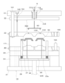
図9乃至図15に示すように、射出成形装置を構成する型内塗装用金型10A(以下、単に「塗装用金型10A」と称する場合もある)は、塗装用固定側金型100A及び可動側金型200から構成され、塗装用固定側金型100A及び可動側金型200を閉じる(型締めする)ことによって塗装用固定側金型100A及び可動側金型200の間で形成された塗装用キャビティ400において、塗装用キャビティ400内に予め配置されている樹脂成形品500Bと、塗装用固定側型板13A及び/または可動側型板23との間にクリアランス400Cを形成し、そのクリアランス400Cに2液混合型の熱硬化性樹脂からなる塗料を充填して、樹脂成形品500Bの表面に熱硬化性樹脂の塗膜500Aが形成された塗装樹脂成形品500を製造し、塗装用固定側金型100A及び可動側金型200を開く(型開きする)ことによって塗装用キャビティ400内で形成された塗装樹脂成形品500が取り出されるようになっている。
なお、金型10Aの材料としては、例えば、機械構造用炭素鋼(S45C,S50C,S55C等)、クロムモリブデン鋼(SCM4等)、炭素工具鋼(SK7等)、ダイス鋼(SKD4,SKD5,SKD6,SKD61等)、高速度鋼(SKH2等)等が使用される。
[First embodiment]
In the first embodiment of the present invention, the injection molding die of the present invention is applied to an in-mold coating die (coating film forming die) 10A for coating and molding a two-component mixed thermosetting resin.
First, the configuration of an in-mold coating mold 10A according to a first embodiment of the present invention will be described with reference mainly to FIGS.
As shown in FIGS. 9 to 15, an in-mold coating mold 10A (hereinafter, sometimes simply referred to as a "coating mold 10A") constituting an injection molding device is composed of a coating fixed mold 100A and a movable mold 200. By closing (clamping) the coating fixed mold 100A and the movable mold 200, a coating cavity 400 is formed between the coating fixed mold 100A and the movable mold 200, and a resin molded product 500B that is previously placed in the coating cavity 400 is formed in the coating cavity 400. A clearance 400C is formed between the painting fixed side mold plate 13A and/or the movable side mold plate 23, and the clearance 400C is filled with paint made of a two-component mixed type thermosetting resin to produce a painted resin molded product 500 in which a coating film 500A of thermosetting resin is formed on the surface of the resin molded product 500B. The painted fixed side metal mold 100A and the movable side metal mold 200 are then opened (mold opening) to remove the painted resin molded product 500 formed in the painting cavity 400.
In addition, examples of materials used for the mold 10A include carbon steel for mechanical construction (S45C, S50C, S55C, etc.), chromium-molybdenum steel (SCM4, etc.), carbon tool steel (SK7, etc.), die steel (SKD4, SKD5, SKD6, SKD61, etc.), and high-speed steel (SKH2, etc.).

塗装用固定側金型100Aは、射出成形装置に固定される側で、塗装用固定側取付板11Aと、塗装用ランナーストリッパープレート12A(以下、単に「塗装用ストリッパープレート12A」と称する場合もある)と、塗装用固定側型板(キャビティプレート、固定側主板、または雌型ともいう)13Aとから構成されている。 The fixed side paint mold 100A is the side that is fixed to the injection molding device and is composed of a fixed side paint attachment plate 11A, a runner stripper plate 12A for paint (hereinafter sometimes simply referred to as the "stripper plate 12A for paint"), and a fixed side paint mold plate (also called the cavity plate, fixed side main plate, or female mold) 13A.

塗装用固定側取付板11Aは、射出成形装置の基盤上に固定される固定盤(図示せず)に取付けられるものである。この塗装用固定側取付板11Aには、必要に応じ、固定盤の中央に形成されている開口に対応させる位置決め用のロケートリング(図示せず)を締め付けボルト等により取付けることができ、中央に孔が形成されているロケートリングを固定盤中央に開いている開口に合わせることで、注入機のノズルN2と塗装用固定側金型100A内に設けられた1次スプルー111との位置を精度よく合わせることができる。 The painting fixed side mounting plate 11A is attached to a fixed platen (not shown) that is fixed on the base of the injection molding machine. If necessary, a locating ring (not shown) for positioning that corresponds to an opening formed in the center of the fixed platen can be attached to this painting fixed side mounting plate 11A by tightening bolts or the like, and by aligning the locating ring, which has a hole formed in the center, with the opening in the center of the fixed platen, the nozzle N2 of the injection machine and the primary sprue 111 provided in the painting fixed side mold 100A can be precisely aligned.

塗装用ランナーストリッパープレート12Aは、スプルー・ランナー樹脂600Aを塗装樹脂成形品500から切り離すためのものであり、塗装用固定側取付板11Aと塗装用固定側型板13Aとの間に配置している。
塗装用固定側型板13Aは、可動側型板23との間で、塗装用キャビティ400を形成するものであり、塗装用ストリッパープレート12Aとの対向面とは反対側の面がパーティング面300である。なお、図9乃至図15においては、塗装用固定側型板13Aのキャビティ形成面310が凹状に形成されている。
The paint runner stripper plate 12A is for separating the sprue/runner resin 600A from the painted resin molded product 500, and is disposed between the paint fixed side attachment plate 11A and the paint fixed side template 13A.
The painting fixed-side template 13A forms a painting cavity 400 between itself and the movable-side template 23, and the surface opposite to the surface facing the painting stripper plate 12A is a parting surface 300. In addition, in Figures 9 to 15, the cavity forming surface 310 of the painting fixed-side template 13A is formed in a concave shape.

塗装用固定側取付板11A及び塗装用ストリッパープレート12Aには、それらを貫通してスプルーブッシュ119が設けられている。このスプルーブッシュ119には、注入機のノズルN2から射出注入された塗料が塗装用金型10Aに最初に流れ込む樹脂流路である1次スプルー111として、塗料が流れる方向に向かって径大な略円錐形の貫通孔が形成されている。この1次スプルー111は、塗料の射出注入方向と同軸に設けられている。なお、スプルーブッシュ119は、塗装用固定側取付板11A及び塗装用ストリッパープレート12Aに挿設されて、塗装用固定側取付板11Aに螺子等の固定具で取付け固定されている。 A sprue bushing 119 is provided through the painting fixed side mounting plate 11A and the painting stripper plate 12A. This sprue bushing 119 has a large diameter, approximately conical through hole formed in the direction in which the paint flows as the primary sprue 111, which is a resin flow path through which the paint injected from the nozzle N2 of the injection machine first flows into the painting mold 10A. This primary sprue 111 is provided coaxially with the paint injection direction. The sprue bushing 119 is inserted into the painting fixed side mounting plate 11A and the painting stripper plate 12A, and is attached and fixed to the painting fixed side mounting plate 11A with a fixing device such as a screw.

塗装用ストリッパープレート12Aと塗装用固定側型板13Aとの間には、1次スプルー111に連通する樹脂流路であるランナー112が1次スプルー111の長さ方向に対して略直角方向に設けられている。
また、塗装用固定側型板13Aには、ランナー112に連通する樹脂流路である2次スプルー113が塗料の射出方向と並行に設けられている。
そして、2次スプルー113の先端部には、塗装用固定側型板13Aのキャビティ形成面310にゲート口を形成したピンゲート(ピンポイントゲートとも云う)114が設けられている。このピンゲート114は、2次スプルー113の軸心上に設けられ、樹脂流路で最小径となる部分であり、塗装用固定側型板13Aのキャビティ形成面310で開口したゲート口を有し、型締め状態で二次スプルー113及び塗装用キャビティ400を連通する。
A runner 112, which is a resin flow path communicating with the primary sprue 111, is provided between the paint stripper plate 12A and the paint fixed side template 13A in a direction approximately perpendicular to the longitudinal direction of the primary sprue 111.
Further, the fixed coating template 13A is provided with a secondary sprue 113, which is a resin flow path communicating with the runner 112, in parallel with the paint injection direction.
A pin gate (also called a pinpoint gate) 114 having a gate opening formed on the cavity forming surface 310 of the painting fixed-side mold plate 13A is provided at the tip of the secondary sprue 113. This pin gate 114 is provided on the axis of the secondary sprue 113, is the part with the smallest diameter in the resin flow path, has a gate opening that opens on the cavity forming surface 310 of the painting fixed-side mold plate 13A, and communicates between the secondary sprue 113 and the painting cavity 400 in the mold clamping state.

2次スプルー113及びその先端部のピンゲート114は、通常、それらの軸線に直交する断面の形状が略円形であって、2次スプルー113は、塗料が流れていく方向の先端側、即ち、ピンゲート114側に向かって断面積を小さく縮径した形状である。好ましくは、先端側に向かって徐々に縮径した形状であり、更に、先端付近では根元側に比べて、断面積の縮小率を大きくするのがより好ましい。また、ピンゲート114は、ゲート先端のゲート口に向かって縮径するテーパを設けた円錐状とするのが好ましく、更に、ゲートランド長さは、ゲート先端のゲート口の直径の例えば、1倍~2倍程度が好ましい。これより、型開きの際に、スプルー111,113及びランナー112で固化した樹脂600Aがスプルー111,113及びランナー112に残らずスプルー111,113及びランナー112から離型しやすく、また、塗装樹脂成形品500の表面において突起状のゲートの切断残りを小さく抑えることができる。なお、ピンゲート114の先端の開口形状は円形であってもよいし、楕円形や扁平形であってもよい。このような形状は、ドリル等の回転物で切削・研磨することで形成することができる。 The secondary sprue 113 and the pin gate 114 at its tip usually have a substantially circular cross-sectional shape perpendicular to their axis, and the secondary sprue 113 has a shape in which the cross-sectional area tapers toward the tip side in the direction in which the paint flows, i.e., toward the pin gate 114. Preferably, the shape tapers gradually toward the tip, and more preferably, the cross-sectional area reduction rate is greater near the tip compared to the base side. Also, the pin gate 114 is preferably conical with a taper that tapers toward the gate opening at the gate tip, and the gate land length is preferably, for example, 1 to 2 times the diameter of the gate opening at the gate tip. As a result, when the mold is opened, the resin 600A solidified in the sprues 111, 113 and the runner 112 does not remain on the sprues 111, 113 and the runner 112, and is easily released from the sprues 111, 113 and the runner 112, and the cutting residue of the protruding gate on the surface of the coated resin molded product 500 can be kept small. The opening shape at the tip of the pin gate 114 may be circular, elliptical, or flat. Such shapes can be formed by cutting and polishing with a rotating object such as a drill.

なお、図9乃至図15においては、塗装用固定側型板13Aと可動側型板23との間に所望とする塗装樹脂成形品500の形状に対応する内面形状の複数の塗装用キャビティ400を形成しており、1次スプルー111から2つ以上に分岐してランナー112が設けられ、その各ランナー112から1つの塗装用キャビティ400に連通する2次スプルー113及びピンゲート114が設けられており、多数個取りの形態としている。 In addition, in Figures 9 to 15, a plurality of coating cavities 400 with an inner shape corresponding to the shape of the desired coated resin molded product 500 are formed between the fixed side coating mold plate 13A and the movable side mold plate 23, and two or more runners 112 are provided branching from the primary sprue 111, and secondary sprues 113 and pin gates 114 are provided that connect each runner 112 to one coating cavity 400, resulting in a multiple-cavity configuration.

また、図9乃至図15においては、2次スプルー113及びピンゲート114は、塗装用固定側型板13Aに穿設された穿孔として形成されているが、本発明を実施する場合には、塗装用固定側型板13Aとは別体で2次スプルー113及びピンゲート114を形成したスプルー・ゲートブッシュを塗装用固定側型板13Aに形成したブッシュ挿入孔に嵌合させる形態として、2次スプルー113及びピンゲート114を塗装用固定側型板13Aに設けてもよい。特に、ゲート口を1mm以下とする場合には、ゲートブッシュを用いることが好ましい。ゲートブッシュであれば、電鋳加工や放電加工によって精度よく小さいゲード口を形成することが比較的容易にできる。ゲートブッシュは分割した部品の組み合わせとし、塗装用固定側型板13Aに形成したブッシュ挿入孔に挿入するようにしてもよい。 9 to 15, the secondary sprue 113 and the pin gate 114 are formed as holes drilled in the fixed side painting template 13A, but when implementing the present invention, the secondary sprue 113 and the pin gate 114 may be provided on the fixed side painting template 13A in such a manner that a sprue-gate bush in which the secondary sprue 113 and the pin gate 114 are formed separately from the fixed side painting template 13A is fitted into a bush insertion hole formed in the fixed side painting template 13A. In particular, when the gate opening is 1 mm or less, it is preferable to use a gate bush. With a gate bush, it is relatively easy to form a small gate opening with high accuracy by electroforming or electric discharge machining. The gate bush may be a combination of divided parts and inserted into a bush insertion hole formed in the fixed side painting template 13A.

このように本実施の形態1の塗装用金型10Aは、塗装用ストリッパープレート12Aと塗装用固定側型板13Aと可動側型板23とを有する3プレート構造であり、塗装用固定側取付板11A及び塗装用ストリッパープレート12Aが、塗料の射出注入方向と同軸に設けられた1次スプルー111を有し、塗装用ストリッパープレート12A及び塗装用固定側型板13Aの間に1次スプルー111に連続し1次スプルー111に対し略直角方向に設けられたランナー112を形成し、また、塗装用固定側型板13Aが、ランナー112と連続し塗料の射出注入方向と並行に設けられた2次スプルー113を有し、その2次スプルー113の先端部には、塗装用固定側型板13Aのキャビティ形成面310にゲート口を形成したピンゲート114を設けている。そして、塗装用固定側金型100A及び可動側金型200の型締め状態で塗装用固定側型板13Aと可動側型板23の間には塗装用キャビティ400が形成され、塗装用固定側型板13Aにおいて2次スプルー113の先端部に形成されたピンゲート114は、キャビティ形成面310に設けたゲート口でキャビティ400と連通する。 Thus, the paint mold 10A of this embodiment 1 has a three-plate structure having a paint stripper plate 12A, a paint fixed side template 13A, and a movable side template 23, and the paint fixed side mounting plate 11A and the paint stripper plate 12A have a primary sprue 111 arranged coaxially with the paint injection direction, and a runner 112 is formed between the paint stripper plate 12A and the paint fixed side template 13A, which is continuous with the primary sprue 111 and arranged approximately perpendicular to the primary sprue 111, and the paint fixed side template 13A has a secondary sprue 113 which is continuous with the runner 112 and arranged parallel to the paint injection direction, and a pin gate 114 is provided at the tip of the secondary sprue 113, which forms a gate opening on the cavity forming surface 310 of the paint fixed side template 13A. When the fixed side paint mold 100A and the movable side mold 200 are clamped, a paint cavity 400 is formed between the fixed side paint mold plate 13A and the movable side mold plate 23, and the pin gate 114 formed at the tip of the secondary sprue 113 in the fixed side paint mold plate 13A communicates with the cavity 400 through a gate opening provided on the cavity forming surface 310.

これら塗装用固定側取付板11A、塗装用ストリッパープレート12A、及び塗装用固定側型板13Aで構成された塗装用固定側金型100Aは、塗装用固定側取付板11Aに、複数本(例えば、4本)のサポートピン161が固着されている。サポートピン161は、塗装用ストリッパープレート12A及び塗装用固定側型板13Aの摺動をガイドするものである。このサポートピン161が、塗装用ストリッパープレート12A及び塗装用固定側型板13Aの各々に設けられている複数本(例えば、4本)のサポートピンブッシュに挿通していることによって、塗装用ストリッパープレート12A及び塗装用固定側型板13Aは、塗装用固定側取付板11Aに対してスライド自在になっている。即ち、塗装用固定側取付板11A、塗装用ストリッパープレート12A、及び塗装用固定側型板13Aはサポートピン161によって連結されており、塗装用ストリッパープレート12A及び塗装用固定側型板13Aは、サポートピン161をガイドとして摺動自在である。更に、サポートピン161は、可動側型板23及びスペーサーブロック24に設けられたブッシュ(貫通孔)にも挿入自在であり、可動側型板23もサポートピン161をガイドとして摺動自在とされる。 The fixed side paint mold 100A, which is composed of the fixed side paint mounting plate 11A, the stripper plate 12A, and the fixed side paint mold plate 13A, has a plurality of (e.g., four) support pins 161 fixed to the fixed side paint mounting plate 11A. The support pins 161 guide the sliding of the stripper plate 12A and the fixed side paint mold plate 13A. The support pins 161 are inserted into a plurality of (e.g., four) support pin bushes provided on the stripper plate 12A and the fixed side paint mold plate 13A, so that the stripper plate 12A and the fixed side paint mold plate 13A can slide freely relative to the fixed side paint mounting plate 11A. That is, the paint stationary side mounting plate 11A, the paint stripper plate 12A, and the paint stationary side template 13A are connected by support pins 161, and the paint stripper plate 12A and the paint stationary side template 13A can slide freely using the support pins 161 as a guide. Furthermore, the support pins 161 can be inserted into bushes (through holes) provided in the movable side template 23 and the spacer block 24, and the movable side template 23 can also slide freely using the support pins 161 as a guide.

また、塗装用固定側取付板11Aには、塗装用ストリッパープレート12Aを貫通し、ランナー112に至るランナーロックピン163(ダルマピンとも云う)が取り付け固定されている。このランナーロックピン163は、塗装用固定側取付板11Aに形成したピン孔に挿入される頭部と、頭部から塗装用ストリッパープレート12Aを貫通するようにして軸方向に延び頭部より小径な軸部と、軸部の先端部でアンダーカット状に形成され、塗装用固定側型板13Aと塗装用ストリッパープレート12Aとの間に形成されるランナー112に突出するランナーロック部とから構成されている。そして、ランナーロックピン163は、ランナー112に至る先端部であるランナーロック部がアンダーカット状に形成されていることにより、ランナー112を係止できることで、塗装用固定側型板13Aと塗装用ストリッパープレート12Aの間が開く際にスプルー・ランナー樹脂600Aを塗装用ストリッパープレート12A側に付着させた状態で、樹脂成形品500Bと切り離すことができるようになっている。なお、塗装用金型10Aに射出注入される塗料は、低粘性であるから、ランナーロック部を折損し難い複雑な形状に加工しなくともランナーロック部を折損し難いものである。故に、ランナーロックピン163は安価な部品で済む。 A runner lock pin 163 (also called a daruma pin) is attached and fixed to the paint fixed side mounting plate 11A, which penetrates the paint stripper plate 12A and reaches the runner 112. This runner lock pin 163 is composed of a head that is inserted into a pin hole formed in the paint fixed side mounting plate 11A, a shaft portion that extends axially from the head to penetrate the paint stripper plate 12A and has a smaller diameter than the head, and a runner lock portion that is formed in an undercut shape at the tip of the shaft portion and protrudes into the runner 112 formed between the paint fixed side template 13A and the paint stripper plate 12A. The runner lock pin 163 has an undercut runner lock portion, which is the tip that reaches the runner 112, and is therefore able to lock the runner 112. This allows the sprue/runner resin 600A to be attached to the paint stripper plate 12A when the paint fixed side mold plate 13A and the paint stripper plate 12A are opened, and the resin molded product 500B can be separated from the sprue/runner resin 600A. The paint injected into the paint mold 10A has low viscosity, so the runner lock portion is unlikely to break even if it is not machined into a complex shape that is unlikely to break. Therefore, the runner lock pin 163 can be an inexpensive part.

更に、塗装用ストリッパープレート12Aと塗装用固定側型板13Aには、1本または複数本のプラーボルト164が挿入されている。このプラーボルト164は、塗装用固定側取付板11Aに取付けられているストップボルト165に螺合してランナーストリッパープレート12Aに取付け固定されており、塗装用固定側型板13Aと塗装用ストリッパープレート12Aとの型開きストロークを制限するようになっている。
プラーボルト164には、一般的に、図示しないスプリングを設けることによって、型開きの際に、最初に塗装用固定側型板13Aと塗装用ストリッパープレート12Aとの間がスプリングの反発力により開くようにし、塗装樹脂成形品500とスプルー・ランナー樹脂600Aとの間のピンゲート114の部分が最初に切断されるようにしている。
このように、本実施の形態1の塗装用金型10Aでは、ピンゲート構造であることにより、塗装樹脂成形品500の突き出し時にゲートがカットされるものではなく、型開き時に塗装樹脂成形品500がゲートカットされる構成である。
Furthermore, one or more puller bolts 164 are inserted into the paint stripper plate 12A and the paint fixed-side mold plate 13A. The puller bolts 164 are screwed into stop bolts 165 attached to the paint fixed-side mounting plate 11A and fixed to the runner stripper plate 12A, so as to limit the mold opening stroke between the paint fixed-side mold plate 13A and the paint stripper plate 12A.
The puller bolt 164 is generally provided with a spring (not shown) so that when the mold is opened, the gap between the painting fixed side template 13A and the painting stripper plate 12A is opened first by the repulsive force of the spring, and the portion of the pin gate 114 between the painted resin molded product 500 and the sprue/runner resin 600A is cut first.
In this way, in the painting mold 10A of this embodiment 1, due to the pin gate structure, the gate is not cut when the painted resin molded product 500 is ejected, but the painted resin molded product 500 is gate cut when the mold is opened.

塗装用固定側金型100Aに対向させる可動側金型200は、射出成形装置の型締め装置の可動盤(図示せず)に取り付けられる側で、塗装用固定側金型100Aに対して進退自在なものであり、可動側取付板21、スペーサーブロック24、エジェクタープレート25、エジェクターピン26、可動側受板29、可動側型板23等から構成されている。 The movable mold 200, which faces the fixed mold 100A for painting, is the side that is attached to the movable platen (not shown) of the mold clamping device of the injection molding device and can move forward and backward relative to the fixed mold 100A for painting, and is composed of a movable mounting plate 21, a spacer block 24, an ejector plate 25, ejector pins 26, a movable receiving plate 29, a movable mold plate 23, etc.

可動側取付板21は、射出成形装置の可動盤に連結されるものであり、中央部にはエジェクターロッド225を通すエジェクターホールが形成されている。
スペーサーブロック24は、可動側取付板21と可動側受板29のとの間で可動側取付板21に固着して取付けられ、エジェクタープレート25及びエジェクターピン26による突き出し動作のための空間を形成する。
The movable side mounting plate 21 is connected to a movable platen of an injection molding machine, and has an ejector hole in the center through which an ejector rod 225 passes.
The spacer block 24 is fixedly attached to the movable mounting plate 21 between the movable mounting plate 21 and the movable receiving plate 29 , and forms a space for the ejection action by the ejector plate 25 and the ejector pin 26 .

エジェクタープレート25は、可動側取付板21と可動側受板29との間に配置されたスペーサーブロック24によって設けられた空間内に配置され、可動側受板29及び可動側型板23側に向かって進退動作するものである。
エジェクターピン26は、エジェクタープレート25に固定されエジェクタープレート25から突設しているものである。このエジェクターピン26は、1本または複数本設けられ、可動側受板29及び可動側型板23やそれに嵌め込まれた入れ子23aを貫通して穿設された孔に挿通し、エジェクターロッド225によるエジェクタープレート25の押出し(前進)により、可動側型板23のパーティング面300に残された塗装樹脂成形品500を突き出すことができるようになっている。
The ejector plate 25 is disposed in the space formed by the spacer block 24 arranged between the movable side mounting plate 21 and the movable side receiving plate 29, and moves forward and backward toward the movable side receiving plate 29 and the movable side mold plate 23.
The ejector pin 26 is fixed to the ejector plate 25 and protrudes from the ejector plate 25. One or more ejector pins 26 are provided and are inserted into holes drilled through the movable-side receiving plate 29 and the movable-side mold plate 23 and the insert 23a fitted therein, so that the ejector rod 225 pushes out (advances) the ejector plate 25 to eject the coated resin molded product 500 remaining on the parting surface 300 of the movable-side mold plate 23.

また、可動側受板(圧受けプレート)29は、スペーサーブロック24に固着されており、ガイドピン166等が取り付け固定される。
可動側型板23は、可動側受板29の前面側に固着され、塗装用固定側型板13Aとの間で、塗装用キャビティ400を形成するものである。この可動側型板23は、射出成形装置の可動盤に取付けられる可動側取付板21に対し、スペーサーブロック24及び可動側受板29を介して固定されている。可動側型板23において塗装用固定側型板13Aとの対向面がパーティング面300である。なお、図1乃至図15では、可動側型板23において凸状の入れ子23aが嵌められておりキャビティ形成面310が凸状である。
Further, the movable side receiving plate (pressure receiving plate) 29 is fixed to the spacer block 24, and a guide pin 166 and the like are attached and fixed thereto.
The movable-side mold plate 23 is fixed to the front side of the movable-side receiving plate 29, and forms a coating cavity 400 between it and the fixed-side paint mold plate 13A. The movable-side mold plate 23 is fixed to the movable-side mounting plate 21, which is attached to the movable platen of the injection molding device, via a spacer block 24 and the movable-side receiving plate 29. The surface of the movable-side mold plate 23 that faces the fixed-side paint mold plate 13A is the parting surface 300. In Figs. 1 to 15, a convex insert 23a is fitted into the movable-side mold plate 23, and the cavity forming surface 310 is convex.

なお、可動側型板23には、リターンピン27が挿通されており、リターンピン27の一端はエジェクタープレート25に固定されている。リターンピン27の周囲には、エジェクタープレート25を後退する方向へ付勢するリターンスプリング28が取り付けられており、このリターンスプリング28の反発力によって、エジェクターピン26による塗装樹脂成形品500の突き出し後にエジェクタープレート25が可動側受板29及び可動側型板23側から離されて元の位置に戻ることができるようになっている。
即ち、エジェクタープレート25、エジェクターピン26、及びリターンピン27等で構成される突き出し機構により、可動側金型200側のキャビティ形成面310に残された塗装樹脂成形品500を突き出すことができるようになっている。
A return pin 27 is inserted through the movable-side mold plate 23, and one end of the return pin 27 is fixed to the ejector plate 25. A return spring 28 that urges the ejector plate 25 in a direction to move backward is attached around the return pin 27, and the repulsive force of the return spring 28 allows the ejector plate 25 to be separated from the movable-side receiving plate 29 and the movable-side mold plate 23 after the ejector pin 26 has ejected the coated resin molded product 500, and to return to its original position.
That is, the ejection mechanism consisting of the ejector plate 25, the ejector pin 26, the return pin 27, etc., is capable of ejecting the coated resin molded product 500 remaining on the cavity forming surface 310 on the movable mold 200 side.

これら塗装用固定側金型100A及び可動側金型200は、可動側金型200の可動側受板29に固着してある複数本(例えば、4本)のガイドピン166が型締めの際に塗装用固定側金型100Aの塗装用固定側型板13Aに設けられている複数個のガイドブッシュ(ガイド軸受け)169に嵌められて摺動をガイドされることにより、位置合わせされる。
また、塗装用固定側金型100A及び可動側金型200は、引張りリンク171により連結されている。引張りリンク171は、その長手方向に延びる長孔を有し、塗装用固定側金型100A及び可動側金型200の型締め状態から型開きしていく際に、塗装用固定側型板13Aと可動側型板23と間の型開きストロークを制限する。
The fixed side painting mold 100A and the movable side mold 200 are aligned by having multiple (e.g., four) guide pins 166 fixed to the movable side receiving plate 29 of the movable side mold 200 fitted into multiple guide bushes (guide bearings) 169 provided on the fixed side painting template 13A of the fixed side painting mold 100A during mold clamping, thereby guiding their sliding.
The painting fixed metal mold 100A and the movable metal mold 200 are connected by a tension link 171. The tension link 171 has a long hole extending in its longitudinal direction, and limits the mold opening stroke between the painting fixed metal mold plate 13A and the movable metal mold plate 23 when the painting fixed metal mold 100A and the movable metal mold 200 are opened from the clamped state.

こうした構成の塗装用固定金型100A及び可動側金型200は、互いに対向されて型内塗装用金型10Aを構成し、塗装用固定金型100A及び可動側金型200が型締めされることで塗装用固定金型100Aと可動側金型200との間で塗装樹脂成形品500の形状に対応する塗装用キャビティ400を形成する。
このとき、本実施の形態1においては、予め、キャビティ形成面310に樹脂成形品500Bが保持された可動側金型200に対し、塗装用固定金型100Aが対向し、型締めされる。そして、型締め状態で、塗装用固定金型100Aと可動側金型200との間で樹脂成形品500Bが配置された塗装用キャビティ400において、樹脂成形品500Bと塗装用固定側型板13Aとの間でクリアランス400Cが形成され、そのクリアランス400Cに塗料が充填されることにより樹脂成形品500Bの表面に塗料が被覆され塗装されることになる。
なお、塗装用固定金型100Aの塗装用固定用型板13Aのキャビティ壁面の形状は、所望とする塗装のパターンや厚みに応じて適宜設定される。
The fixed painting mold 100A and the movable side mold 200 configured in this manner are opposed to each other to form the in-mold painting mold 10A, and when the fixed painting mold 100A and the movable side mold 200 are clamped together, a painting cavity 400 corresponding to the shape of the painted resin molded product 500 is formed between the fixed painting mold 100A and the movable side mold 200.
At this time, in the present embodiment 1, the painting fixed metal mold 100A is opposed to and clamped against the movable metal mold 200, which has the resin molded product 500B held in advance on its cavity forming surface 310. Then, in the clamped state, a clearance 400C is formed between the painting fixed metal mold 100A and the movable metal mold 200 in the painting cavity 400 in which the resin molded product 500B is disposed, and the paint is filled into the clearance 400C, so that the surface of the resin molded product 500B is coated with the paint and painted.
The shape of the cavity wall surface of the painting fixing template 13A of the painting fixed metal mold 100A is appropriately set according to the desired pattern and thickness of the paint.

ここで、本発明者らは鋭意実験研究の結果、塗装用金型10Aを構成する塗装用固定側金型100Aの塗装用固定側型板13Aと可動側金型200の可動側型板23との分離面であるパーティング面300の表面粗さRzを、0.8μm以下、好ましくは、0.6μm以下、より好ましくは、0.4μm以下、更に好ましくは、0.2μm以下とすることで、2液混合型の熱硬化性樹脂の塗料を塗装用キャビティ400のクリアランス400Cに充填して樹脂成形品500Bの表面に流したときでも、2液混合型の熱硬化性樹脂の塗料が塗装用固定側型板13Aと可動側型板23の合わせ面(当接面)であるパーティング面300に漏出するのが抑制されてバリの発生が防止されることを見出した。 Here, the inventors have found through intensive experimental research that by setting the surface roughness Rz of the parting surface 300, which is the separation surface between the fixed-side painting mold plate 13A of the fixed-side painting mold 100A and the movable-side mold plate 23 of the movable-side mold 200 constituting the painting mold 10A, to 0.8 μm or less, preferably 0.6 μm or less, more preferably 0.4 μm or less, and even more preferably 0.2 μm or less, even when a two-component thermosetting resin paint is filled into the clearance 400C of the painting cavity 400 and poured onto the surface of the resin molded product 500B, the two-component thermosetting resin paint is prevented from leaking onto the parting surface 300, which is the mating surface (contact surface) of the fixed-side painting mold plate 13A and the movable-side mold plate 23, and thus the occurrence of burrs is prevented.

これは、塗装用固定側型板13Aと可動側型板23のパーティング面300の表面粗さRzが0.8μm以下、好ましくは、0.6μm以下、より好ましくは、0.4μm以下、更に好ましくは、0.2μm以下であり、塗装用固定側型板13と可動側型板23のパーティング面300が高精度な平滑面であることにより塗装用固定側型板13と可動側型板23とのパーティング面300の高い密着度が得られ、即ち、塗装用固定側型板13と可動側型板23とのパーティング面300がメタルタッチし、また、高精度な平滑面に対する塗料の濡れ性が低く、それ故、塗装用固定側型板13Aと可動側型板23のパーティング面300に塗料が漏出し難くバリの発生が抑えられていると考える。 This is because the surface roughness Rz of the parting surface 300 between the fixed side painting template 13A and the movable side template 23 is 0.8 μm or less, preferably 0.6 μm or less, more preferably 0.4 μm or less, and even more preferably 0.2 μm or less. The parting surface 300 between the fixed side painting template 13 and the movable side template 23 is a highly accurate smooth surface, which provides a high degree of adhesion between the parting surface 300 between the fixed side painting template 13 and the movable side template 23, i.e., the parting surface 300 between the fixed side painting template 13 and the movable side template 23 is in metal-to-metal contact, and the wettability of the paint to the highly accurate smooth surface is low. Therefore, it is believed that paint is less likely to leak onto the parting surface 300 between the fixed side painting template 13A and the movable side template 23, and the occurrence of burrs is suppressed.

また、塗料が2液硬化型の熱硬化性樹脂であるから、樹脂成形品500Bとキャビティ形成面310との間のクリアランス400Cに塗料を十分に行き渡らせることできる。当然、高い注入圧力を要しないから塗料の漏れ防止にもなる。 In addition, because the paint is a two-component curing thermosetting resin, the paint can be sufficiently spread into the clearance 400C between the resin molded product 500B and the cavity forming surface 310. Naturally, since high injection pressure is not required, paint leakage is also prevented.

加えて、本実施の形態1の塗装用金型10Aにおいては、塗装用固定側金型100Aのランナー112は、塗装用固定側型板13A及び塗装用ストリッパープレート12Aの間に形成され、塗装用固定側型板13A及び塗装用ストリッパープレート12Aの分割面700の表面粗さRzも0.8μm以下、好ましくは、0.6μm以下、より好ましくは、0.4μm以下、更に好ましくは、0.2μm以下としている。
よって、粘性が低い2液混合型である熱硬化性樹脂からなる塗料がランナー112を通過する際でも、塗装用固定側型板13A及び塗装用ストリッパープレート12の分割面700において、塗装用固定側型板13A及び塗装用ストリッパープレート12Aが当接する合わせ面への塗料の漏れ(侵入)を防止できる。このため、漏れた余分な塗料を排出する処理の負担を軽減でき、成形サイクルを良好とし、塗装樹脂成形品500の生産性を上げることができる。
In addition, in the painting mold 10A of this embodiment 1, the runner 112 of the painting fixed side mold 100A is formed between the painting fixed side template 13A and the painting stripper plate 12A, and the surface roughness Rz of the parting surface 700 of the painting fixed side template 13A and the painting stripper plate 12A is also 0.8 μm or less, preferably 0.6 μm or less, more preferably 0.4 μm or less, and even more preferably 0.2 μm or less.
Therefore, even when paint made of a two-component thermosetting resin having low viscosity passes through the runner 112, it is possible to prevent the paint from leaking (entering) into the mating surface where the paint fixed side template 13A and the paint stripper plate 12A come into contact at the dividing surface 700 of the paint fixed side template 13A and the paint stripper plate 12. This reduces the burden of discharging the excess leaked paint, improves the molding cycle, and increases the productivity of the coated resin molded product 500.

塗装用固定側金型100Aの塗装用固定側型板13Aと可動側金型200の可動側型板23の分離面であるパーティング面300の表面粗さRzを0.8μm以下、好ましくは、0.6μm以下、より好ましくは、0.4μm以下、更に好ましくは、0.2μm以下や、塗装用固定側型板13A及び塗装用ストリッパープレート12Aの分割面700の表面粗さを0.8μm以下、好ましくは、0.6μm以下、より好ましくは、0.4μm以下、更に好ましくは、0.2μm以下は、例えば、金型材料である硬質基材をサンドブラスト処理や、砥石、サンドペーパー、ダイヤモンドペース等で研磨する研磨処理や、プラズマ窒化処理、硬質クロム、無電解ニッケル等のメッキ処理、アルマイト処理、フッ素樹脂等の樹脂コーティング、セラミックコーティング、マイクロショットピーニング等の焼き入れ・コーティング処理(例えば、CVD法、PVD法、DLC法、TIN法等)の表面処理等により面精度を向上させ鏡面状としたものである。
なお、表面粗さは、レーザー顕微鏡(株式会社東京精密製、サーフコムNEX140DX)を用いて測定し、JIS B 0601:2001にしたがい最大高さ粗さ(Rz)で求めたものである。
The surface roughness Rz of the parting surface 300, which is the separation surface between the painting fixed side mold plate 13A of the painting fixed side mold 100A and the movable side mold plate 23 of the movable side mold 200, is 0.8 μm or less, preferably 0.6 μm or less, more preferably 0.4 μm or less, and even more preferably 0.2 μm or less. The surface roughness of the parting surface 700 of the painting fixed side mold plate 13A and the painting stripper plate 12A is 0.8 μm or less, preferably 0.6 μm or less, more preferably 0.4 μm or less, and even more preferably 0.2 μm or less. The surface precision of the hard base material, which is the mold material, is improved to a mirror-like finish by, for example, sandblasting the hard base material, or polishing with a grindstone, sandpaper, diamond paste, or the like; surface treatment such as plasma nitriding, plating with hard chrome, electroless nickel, or the like, anodizing, resin coating such as fluororesin, ceramic coating, and hardening/coating treatment such as micro shot peening (for example, CVD, PVD, DLC, TIN, or the like).
The surface roughness was measured using a laser microscope (Surfcom NEX140DX, manufactured by Tokyo Seimitsu Co., Ltd.) and determined as the maximum height roughness (Rz) in accordance with JIS B 0601:2001.

ところで、本実施の形態1において、塗装用固定側金型100A内で樹脂成形品500Bの表面に塗装される塗料としては、2液混合型の熱硬化性樹脂が使用される。2液混合型の熱硬化性樹脂は、熱によって重合反応が進行して硬化するものであり、例えば、シリコーン系樹脂、フェノール系樹脂、エポキシ系樹脂、ポリウレタン系樹脂、ポリイミド系樹脂、ビニル系樹脂、アルキド系樹脂、メラミン樹脂、ユリア樹脂、不飽和ポリエステル樹脂等がある。こうした2液混合型の熱硬化性樹脂は、熱硬化性樹脂を含む主剤(第1液)と、重合開始剤を含む硬化剤(第2液)を混合して注入機のノズルN2から塗装用固定側金型100Aに射出注入される。熱硬化性樹脂を含む第1液や重合開始剤を含む第2液には、顔料、セラミック、金属、繊維(炭素繊維・ガラス繊維、セルロース繊維、アラミド繊維等)、ワックス、難燃剤、酸化防止剤、熱安定剤等の添加剤が含まれていてもよい。なお、2液混合型の熱硬化性樹脂の第1液と第2液とは、混合されると室温においても緩やかに重合反応が進行するため、通常、塗装用金型10Aに射出注入する間際に混合されることが好ましい。このような2液混合型の熱硬化性樹脂は、主剤が硬化剤と混合されるまでは室温安定性が良く、保管性に優れるものである。また、2液混合型の熱硬化性樹脂は、ラジカル反応で硬化が進行し、三次元の網目構造を形成して塗膜となるものであり、2液混合型の熱硬化性樹脂を硬化させてなる塗膜500Aは3次元の網目構造を有し、耐熱性や耐溶剤性に優れるものである。 In the present embodiment 1, a two-liquid mixed type thermosetting resin is used as the paint applied to the surface of the resin molded product 500B in the fixed side coating mold 100A. The two-liquid mixed type thermosetting resin is cured by the polymerization reaction caused by heat, and examples of such resins include silicone resins, phenolic resins, epoxy resins, polyurethane resins, polyimide resins, vinyl resins, alkyd resins, melamine resins, urea resins, and unsaturated polyester resins. Such two-liquid mixed type thermosetting resins are mixed with a base material (first liquid) containing a thermosetting resin and a curing agent (second liquid) containing a polymerization initiator, and are injected into the fixed side coating mold 100A from the nozzle N2 of the injection machine. The first liquid containing a thermosetting resin and the second liquid containing a polymerization initiator may contain additives such as pigments, ceramics, metals, fibers (carbon fibers, glass fibers, cellulose fibers, aramid fibers, etc.), wax, flame retardants, antioxidants, and heat stabilizers. In addition, since the first and second liquids of the two-liquid mixed thermosetting resin undergo a gradual polymerization reaction even at room temperature when mixed, it is usually preferable to mix them just before injection into the coating mold 10A. Such two-liquid mixed thermosetting resins have good room temperature stability until the main agent is mixed with the curing agent, and have excellent storage properties. In addition, the two-liquid mixed thermosetting resin cures through a radical reaction, forming a three-dimensional network structure to become a coating film, and the coating film 500A formed by curing the two-liquid mixed thermosetting resin has a three-dimensional network structure and is excellent in heat resistance and solvent resistance.

本実施の形態1において、塗装用固定側金型100A内で樹脂成形品500Bを被覆する塗料(被覆剤)である2液混合型の熱硬化性樹脂は、塗料注入機の樹脂射出ノズルN2から射出されるときの樹脂粘度が、例えば、50℃~90℃で4×10²(mPa・s)以下、好ましくは、8×101(mPa・s)以下、より好ましくは、4×101(mPa・s)以下である。
射出成形において一般的に用いられている熱可塑性樹脂のペレットを溶融して、クリアランス400Cに充填させる場合、ゲートを大きくして樹脂を流れやすくする必要があるが、所定の低粘性のものであれば、流動性がよく、ゲート径の小さいピンゲート114であっても、樹脂の流れを確保でき、薄厚のクリアランス400Cの隅々に行き渡らせることが可能である。即ち、薄厚や複雑な形状とする塗装成形であっても、充填不良を防止できる。また、こうした2液混合反応型の熱硬化性樹脂であれば、熱可塑性樹脂よりも温度変化による膨張収縮が抑えられるから、厚肉(例えば、1mm~6mmの硬化厚み)や複雑な形状とする塗装成形であっても、ヒケ不良を防止できる。そして、型締め状態で塗料を射出注入し、更に、塗料の膨張収縮が生じ難いことで、空気の逆流による硬化阻害も生じ難いものである。加えて、流動性がよいので、多点ゲートであってもウェルドラインを生じさせ難いものとなる。
In this embodiment 1, the two-component mixed thermosetting resin, which is the paint (coating agent) that coats the resin molded product 500B within the fixed side paint mold 100A, has a resin viscosity when injected from the resin injection nozzle N2 of the paint injection machine at 50°C to 90°C of, for example, 4 x 10 2 (mPa·s) or less, preferably 8 x 10 1 (mPa·s) or less, and more preferably 4 x 10 1 (mPa·s) or less.
When melting pellets of thermoplastic resin generally used in injection molding and filling the clearance 400C, it is necessary to make the gate larger to make the resin flow easily, but if it is a resin with a certain low viscosity, it has good fluidity, and even with a pin gate 114 with a small gate diameter, the flow of the resin can be ensured and it is possible to spread it to every corner of the thin clearance 400C. That is, even in paint molding with a thin thickness or a complex shape, filling defects can be prevented. In addition, such a two-liquid mixed reaction type thermosetting resin can suppress expansion and contraction due to temperature changes more than thermoplastic resins, so sink defects can be prevented even in paint molding with a thick wall (for example, a cured thickness of 1 mm to 6 mm) or a complex shape. And, since the paint is injected in a clamped state and the paint is less likely to expand and contract, curing inhibition due to backflow of air is less likely to occur. In addition, since the fluidity is good, it is less likely to cause weld lines even in multi-point gates.

2液混合型の熱硬化性樹脂としては、好ましくは、70℃以上で粘性が1.15×10²(mPa・s)よりも柔らかく、また、30℃以下で粘性が6×10²(mPa・s)以下であり、より好ましくは、30℃以下で1×10²(mPa・s)以下、更に好ましくは、30℃以下で8×101(mPa・s)以下である。例えば、ポリウレタンやシリコーンが使用される。より好ましくは、常温(室温)硬化型の2液混合型の熱硬化性樹脂である。
因みに、一般合成樹脂(熱可塑性樹脂)の260℃の温度の粘度は1.0×10⁵~1.0×10⁶(mPa・s)であるのに対し、20℃の水の粘度は1.0(mPa・s)であり、2液混合型のポリウレタン(75℃)の粘度は水の粘度に近似している。一般論からしてポリウレタン(75℃)の粘度が一般合成樹脂の1000~10000倍粘度が低く、水に近い粘度である。
一般合成樹脂の260℃の温度の粘度では、成形温度を高くする必要があり、金型の耐熱性が要求される。
これに対し、好ましくは、70℃以上で粘性が1.15×10²(mPa・s)よりも柔らかく、30℃以下で粘性が6×10²(mPa・s)以下であり、より好ましくは、30℃以下で1×10²(mPa・s)以下、更に好ましくは、30℃以下で8×101(mPa・s)以下である2液混合型の熱硬化性樹脂を射出注入するものでは、硬化温度の加熱で済むから、金型コストやエネルギコストを抑えることができ、射出成形装置の管理も容易である。
The two-part mixture type thermosetting resin preferably has a viscosity of less than 1.15×10 2 (mPa·s) at 70° C. or higher, and a viscosity of 6×10 2 (mPa·s) or less at 30° C. or lower, more preferably 1×10 2 (mPa·s) or less at 30° C. or lower, and even more preferably 8×10 1 (mPa·s) or less at 30° C. or lower. For example, polyurethane or silicone is used. More preferably, it is a two-part mixture type thermosetting resin that cures at room temperature.
Incidentally, the viscosity of general synthetic resins (thermoplastic resins) at a temperature of 260°C is 1.0 x 10⁵ to 1.0 x 10⁶ (mPa·s), while the viscosity of water at 20°C is 1.0 (mPa·s), and the viscosity of two-liquid mixed polyurethane (75°C) is close to the viscosity of water. Generally speaking, the viscosity of polyurethane (75°C) is 1,000 to 10,000 times lower than that of general synthetic resins, and is close to that of water.
With the viscosity of general synthetic resins at a temperature of 260° C., the molding temperature must be high, and the mold must be heat resistant.
In contrast, when a two-component mixed thermosetting resin is injected, which preferably has a viscosity of less than 1.15 x 10² (mPa·s) at 70°C or above and a viscosity of 6 x 10² (mPa·s) or less at 30°C or below, more preferably 1 x 10² (mPa·s) or less at 30°C or below, and even more preferably 8 x 101 (mPa·s) or less at 30°C or below, it only requires heating to the curing temperature, so mold and energy costs can be reduced and the injection molding equipment is easy to manage.

例えば、2液混合型の熱硬化性樹脂としてポリウレタンを用いる場合には、主剤のポリオールB(Puroclear 3351 IT)と硬化剤のイソシアネートA(Puronate 960/1)が混合されて塗装用金型10Aに射出注入される。
即ち、イソシアネートAとポリオールBとの2液混合タイプで、70℃~90℃で液混合タイプの粘性が1.15×10²(mPa・s)よりも柔らかく、また、30℃以下で粘性が6×10²(mPa・s)以下、より好ましくは、30℃以下で1×10²(mPa・s)以下、更に好ましくは、30℃以下で8×101(mPa・s)以下であるものである。
イソシアネートAとポリオールBとの2液混合型の熱硬化性樹脂では、60~90℃で粘性が弱くなり、60~90℃の範囲で比較的低い粘性が安定していることから、この温度範囲で射出すると、流動性が高いことで、薄厚や複雑な形状に対応するクリアランス400Cであっても、ポリウレタン樹脂を隅々まで充填させることができる。特に、このようなウレタン結合を有する共重合からなるポリマーの塗料は、熱可塑性樹脂からなる樹脂成形品500Bとの密着性が良好で適度な伸び、硬さ、弾性があり塗膜500Aとして好適である。
For example, when polyurethane is used as the two-liquid mixed thermosetting resin, the main component polyol B (Puroclear 3351 IT) and the hardener isocyanate A (Puronate 960/1) are mixed and injected into the coating mold 10A.
That is, it is a two-liquid mixture type of isocyanate A and polyol B, and the viscosity of the liquid mixture type is softer than 1.15 x 10² (mPa·s) at 70°C to 90°C, and the viscosity is 6 x 10² (mPa·s) or less at 30°C or less, more preferably 1 x 10² (mPa·s) or less at 30°C or less, and even more preferably 8 x 101 (mPa·s) or less at 30°C or less.
In the case of a two-part thermosetting resin made of isocyanate A and polyol B, the viscosity becomes weak at 60 to 90° C., and a relatively low viscosity is stable in the range of 60 to 90° C., so when injected in this temperature range, the polyurethane resin has high fluidity and can fill every corner, even in the clearance 400C that corresponds to a thin thickness or a complex shape. In particular, a coating of a polymer made of a copolymer having such a urethane bond has good adhesion to the resin molded product 500B made of a thermoplastic resin, and has appropriate elongation, hardness, and elasticity, making it suitable for the coating film 500A.

次に、本実施の形態1に係る型内塗装用金型100Aを備える射出成形用の2色成形金型1について、図1乃至図15を参照して、説明する。
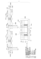
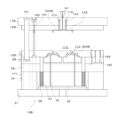
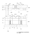
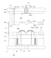
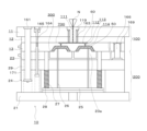
本実施の形態1の射出成形用の2色成形金型1は、図1に示すように、成形品用固定側金型(1次固定側金型)100B、塗装用固定側金型(2次固定側金型)100A、及び可動側金型200を備え、成形品用固定側金型100B及び可動側金型200により成形品用金型10Bが構成され、また、上述したように、塗装用固定側金型100A及び可動側金型200により型内塗装用金型(成形品被覆用金型)10Aが構成される。
Next, a two-color injection molding die 1 including an in-mold coating die 100A according to the first embodiment will be described with reference to FIGS.
As shown in FIG. 1, the two-color molding die 1 for injection molding in this embodiment 1 comprises a fixed side die for molded products (primary fixed side die) 100B, a fixed side die for painting (secondary fixed side die) 100A, and a movable side die 200, with the fixed side die for molded products 100B and the movable side die 200 constituting the die for molded products 10B, and as described above, the fixed side die for painting 100A and the movable side die 200 constituting the die for in-mold painting (die for coating molded products) 10A.

図1乃至図8に示すように、本実施の形態1の成形品用固定側金型(1次固定側金型)100Bも、上述の塗装用固定側金型(2次固定側金型)100Aと同様、射出成形装置に固定される側で、成形品用固定側取付板11Bと、成形品用ランナーストリッパープレート12B(以下、単に「成形品用ストリッパープレート12B」と称する場合がある)と、成形品用固定側型板(キャビティプレート、固定側主板、または雌型ともいう)13Bとから構成されている。 As shown in Figures 1 to 8, the fixed side mold for molded products (primary fixed side mold) 100B of this embodiment 1, like the fixed side mold for painting (secondary fixed side mold) 100A described above, is composed of a fixed side attachment plate for molded products 11B, a runner stripper plate for molded products 12B (hereinafter sometimes simply referred to as "stripper plate for molded products 12B"), and a fixed side mold plate for molded products (also called a cavity plate, fixed side main plate, or female mold) 13B on the side fixed to the injection molding device.

成形品用固定側金型100Bにおいても、上述の塗装用固定側金型100Aと同様に、成形品用固定側取付板11B及び成形品用ストリッパープレート12Bには、それらを貫通して取付けられたスプルーブッシュ119により1次スプルー111が設けられている。また、成形品用固定側取付板11B及び成形品用ストリッパープレート12Bとの間には、1次スプルー111に連通する樹脂流路であるランナー112が1次スプルー111に対して略直角方向に設けられている。
更に、成形品用固定側型板13Bには、ランナー112に連通する樹脂流路である2次スプルー113が樹脂の射出方向に並行に設けられ、2次スプルー113の先端部に、キャビティ形成面310にゲート口を形成したピンゲート114が設けられている。サポートピン161、ランナーロックピン163、ガイドピン166、プラーボルト164、ストップボルト165、引張リンク171等を有することについても上述の塗装用固定側金型100Aと同様であるから、ここではその詳細な説明は省略する。
In the fixed mold for molded products 100B, similarly to the fixed mold for painting 100A described above, the fixed attachment plate for molded products 11B and the stripper plate for molded products 12B are provided with a primary sprue 111 by a sprue bushing 119 that penetrates and is attached thereto. In addition, a runner 112, which is a resin flow path that communicates with the primary sprue 111, is provided between the fixed attachment plate for molded products 11B and the stripper plate for molded products 12B in a direction approximately perpendicular to the primary sprue 111.
Furthermore, the fixed mold plate 13B for molded product has a secondary sprue 113, which is a resin flow path communicating with the runner 112, provided parallel to the resin injection direction, and a pin gate 114 is provided at the tip of the secondary sprue 113, the pin gate 114 having a gate port formed in the cavity forming surface 310. The fixed mold plate 13B for molded product also has support pins 161, runner lock pins 163, guide pins 166, puller bolts 164, stop bolts 165, tension links 171, etc., which are similar to those of the fixed mold plate 100A for painting described above, and therefore detailed description thereof will be omitted here.

即ち、成形品用固定側金型100Bにおいても、ピンゲート構造であることにより、型開き時に樹脂成形品500Bがゲートカットされる構成である。
そして、この成形品用固定側金型100Bは、図示しない駆動機構により可動側金型200の可動側型板23に対面するよう移動され、型締めされたときに、可動側型板23及び成形品用固定側型板13Aとの間に所望とする樹脂成形品500Bの形状に対応する内面形状の複数の成形品用キャビティ800を形成する。なお、図1乃至図8において、成形品用固定側金型100Bにおいても、1次スプルー111から2つ以上に分岐してランナー112が設けられ、その各ランナー112から1つの成形品用キャビティ800に連通する2次スプルー113及びピンゲートが114設けられており、多数個取りの形態としている。
That is, since the fixed die 100B for a molded product also has a pin gate structure, the resin molded product 500B is gate cut when the die is opened.
This fixed mold for molded product 100B is moved by a drive mechanism (not shown) so as to face the movable mold plate 23 of the movable mold 200, and when the molds are clamped, a plurality of molded product cavities 800 having an inner shape corresponding to the shape of the desired resin molded product 500B are formed between the movable mold plate 23 and the fixed mold for molded product 13A. In addition, in Figures 1 to 8, the fixed mold for molded product 100B also has runners 112 branching from a primary sprue 111 into two or more, and secondary sprues 113 and pin gates 114 communicating with one molded product cavity 800 from each of the runners 112 are provided, making it a multiple-cavity type.

こうして塗装用固定側金型100Aと同様の構成の成形品用固定金型100Bは、上述した可動側金型200と対向することで成形品用金型10Bを構成し、成形品用固定金型100B及び可動側金型200の型締めにより成形品用固定金型100Bと可動側金型200との間で樹脂成形品500Bの形状に対応する成形品用キャビティ800を形成する。
なお、成形品用固定側型板13Bは、塗装用固定側型板13Aとは形状が相違し、例えば、成形品用固定金型100Bの成形品用固定側型板13Bと可動側金型200の可動側型板23との間で形成される成形品用キャビティ800が、塗装用固定金型100Aの塗装用固定側型板13Aと可動側金型200の可動側型板23との間で形成される塗装用キャビティ400よりも小さく形成される。
In this way, the fixed mold for molded products 100B, which has the same configuration as the fixed mold for painting 100A, faces the movable mold for molded products 200 described above to form the mold for molded products 10B, and by clamping the fixed mold for molded products 100B and the movable mold for molded products 200, a cavity for molded products 800 corresponding to the shape of the resin molded product 500B is formed between the fixed mold for molded products 100B and the movable mold for molded products 200.
In addition, the fixed side mold plate 13B for molded products has a different shape from the fixed side mold plate 13A for painting. For example, the cavity 800 for molded products formed between the fixed side mold plate 13B for molded products of the fixed mold for molded products 100B and the movable side mold plate 23 of the movable side mold 200 is smaller than the cavity 400 for painting formed between the fixed side mold plate 13A for painting of the fixed mold for painting 100A and the movable side mold plate 23 of the movable side mold 200.

こうした成形品用固定金型100B及び可動側金型200で構成される成形品用金型10Bで樹脂成形品500Bを形成する樹脂としては、塗装樹脂成形品500の製品用途等に応じて設定され、例えば、通常の熱可塑性の射出成形樹脂やエンジニアリングプラスチックを使用でき、特に限定されないが、成形しやすいものが好ましい。具体的には、アクリロニトリルブタジエンスチレン系樹脂(ABS系樹脂)、ポリエチレン系樹脂、ポリエステル系樹脂、ポリアミド系樹脂、ポリプロピレン系樹脂、ポリエチレンテレフタレート系樹脂、ポリブチレンテレフタレート系樹脂、ポリカーボネート系樹脂、ポリオレフィン系樹脂(例えば、エチレン酢酸ビニルポリマー等)、ポリ塩化ビニル系樹脂、ポリ塩化ビニリデン系樹脂、ポリイミド系樹脂、ポリアリレート系樹脂、ポリエーテルイミド系樹脂等が使用される。一般的には、樹脂成形品500Bを形成する溶融樹脂の粘度は、熱硬化性樹脂からなる塗料の粘度よりも高粘度である。なお、熱硬化性樹脂の塗料は、こうした樹脂成形品500Bの樹脂と相性、密着が良いものが好適に使用される。 The resin used to form the resin molded product 500B using the molded product mold 10B, which is composed of the fixed mold for molded products 100B and the movable mold 200, is set according to the product application of the coated resin molded product 500, and can be, for example, a normal thermoplastic injection molding resin or engineering plastic. Although not particularly limited, it is preferable to use one that is easy to mold. Specifically, acrylonitrile butadiene styrene resin (ABS resin), polyethylene resin, polyester resin, polyamide resin, polypropylene resin, polyethylene terephthalate resin, polybutylene terephthalate resin, polycarbonate resin, polyolefin resin (e.g., ethylene vinyl acetate polymer, etc.), polyvinyl chloride resin, polyvinylidene chloride resin, polyimide resin, polyarylate resin, polyetherimide resin, etc. are used. Generally, the viscosity of the molten resin that forms the resin molded product 500B is higher than the viscosity of a paint made of a thermosetting resin. In addition, it is preferable to use a thermosetting resin paint that has good compatibility and adhesion with the resin of the resin molded product 500B.

これら成形品用固定側金型100B、塗装用固定側金型100A、及び可動側金型200を備えた2色成形金型1を有する射出成型装置は、可動側金型200に対面させる固定側金型を切り替えるための、図示しない駆動機構(切替え機構)を備え、その駆動機構により可動側金型200に対面させる固定側金型を成形品用固定側金型100Bまたは塗装用固定側金型100Aに入れ替える。
成形品用固定側金型100Bまたは塗装用固定側金型100Aを切り替える駆動機構としては、例えば、射出成型装置の可動盤や可動盤に取付けた回転盤に可動側金型200を固定し、可動盤や可動盤に取付けた回転盤を回転させることで、可動側金型200に対面させる固定側金型を成形品用固定側金型100Bまたは塗装用固定側金型100Aに切り替えることが可能である。或いは、射出成型装置の可動盤や可動盤に取付けた回転盤に成形品用固定側金型100B及び塗装用固定側金型100Aを固定し、可動盤や可動盤に取付けた回転盤を回転させることで、可動側金型200に対面させる固定側金型を切り替えることも可能である。
An injection molding apparatus having a two-color molding mold 1 equipped with the fixed side mold for molded products 100B, the fixed side mold for painting 100A, and the movable side mold 200 is equipped with a drive mechanism (switching mechanism) not shown in the figure for switching the fixed side mold to be faced to the movable side mold 200, and the drive mechanism switches the fixed side mold to be faced to the movable side mold 200 to the fixed side mold for molded products 100B or the fixed side mold for painting 100A.
As a driving mechanism for switching between the fixed side mold for molded products 100B and the fixed side mold for painting 100A, for example, the movable side mold 200 can be fixed to a movable platen of an injection molding device or a rotating platen attached to the movable platen, and the movable platen or the rotating platen attached to the movable platen can be rotated to switch the fixed side mold to be opposed to the movable side mold 200 to the fixed side mold for molded products 100B or the fixed side mold for painting 100A. Alternatively, the fixed side mold for molded products 100B and the fixed side mold for painting 100A can be fixed to a movable platen of an injection molding device or a rotating platen attached to the movable platen, and the fixed side mold to be opposed to the movable side mold 200 can be switched by rotating the movable platen or the rotating platen attached to the movable platen.

なお、成形品用固定側金型100B、塗装用固定側金型100A、及び可動側金型200を備えた2色成形金型1を有する射出成型装置は、図示しない金型温度調節機構を有する。金型温度調節機構において金型の温度を調節する媒体は水であってもよいし油であってもよいし、ヒータを用いてもよく、成形品用固定側金型100B及び可動側金型200の間の成形品用キャビティ800に充填された成形品用樹脂を固化する温度や、樹脂成形品500Bの表面に流れた2液混合型の熱硬化性樹脂の塗料が所定時間(例えば、数秒以内)で硬化する温度に設定できればよい。
また、2色成形金型1を備えた射出成形装置においては、2色成形金型1の型開き、型閉じを行うための型締め機構を有する。この型締め機構としては、例えば、油圧シリンダ等や電磁シリンダ等を用いてトグル式の型締め機構や直圧式の型締め機構を使用することができる。
The injection molding device having the two-color molding die 1 equipped with the fixed die 100B for molded products, the fixed die 100A for painting, and the movable die 200 has a die temperature adjustment mechanism (not shown). The medium for adjusting the temperature of the die in the die temperature adjustment mechanism may be water or oil, or a heater may be used, and it is sufficient if the temperature can be set to a temperature at which the resin for molded products filled in the cavity 800 for molded products between the fixed die 100B for molded products and the movable die 200 for molded products is solidified, or a temperature at which the paint of two-liquid mixed thermosetting resin flowing on the surface of the resin molded product 500B is hardened within a predetermined time (for example, within a few seconds).
Moreover, the injection molding apparatus equipped with the two-color molding die 1 has a clamping mechanism for opening and closing the two-color molding die 1. As this clamping mechanism, for example, a toggle-type clamping mechanism or a direct pressure-type clamping mechanism using a hydraulic cylinder or an electromagnetic cylinder can be used.

次に、このような成形品用固定側金型100B、塗装用固定側金型100A、及び可動側金型200を備えた2色成形金型1によって塗装樹脂成形品500を製造する方法について説明する。
初めに、成形品用固定側金型100Bを可動側金型200に対向させて可動側金型200及び成形品用固定側金型100Bを型締めし、そこに樹脂成形品500Bを形成するための熱可塑性樹脂等からなる成形品用樹脂を射出して、可動側金型200及び成形品用固定側金型100B内で成形品用樹脂を成形し樹脂成形品500Bを形成する成形品形成工程が実施される。その後、成形品用固定側金型100B及び可動側金型200を型開きし、樹脂成形品500Bが付いている可動側金型200に対向させる固定側金型を成形品用固定側金型100Bから塗装用固定側金型100Aに切替えて可動側金型200及び塗装用固定側金型100Aを型締めし、そこに塗料を射出注入して可動側金型200及び塗装用固定側金型100A内で樹脂成形品500Bの表面を2液混合型の熱硬化性樹脂からなる塗料で被覆し樹脂成形品500Bの表面に2液混合型の熱硬化性樹脂からなる塗膜500Aを形成する型内塗装工程が実施される。これより、樹脂成形品500Bが塗装されて塗膜500Aにより被覆された塗装樹脂成形品500が得られる。
Next, a method for manufacturing a painted resin molded product 500 using the two-color molding die 1 including the molded product fixed die 100B, the painting fixed die 100A, and the movable die 200 will be described.
First, the fixed side mold for molded products 100B is placed opposite the movable side mold 200, the movable side mold 200 and the fixed side mold for molded products 100B are clamped together, and a resin for molded products made of a thermoplastic resin or the like is injected into the molded product to form the resin molded product 500B. The molded product formation process is then carried out in which the resin for molded products is molded within the movable side mold 200 and the fixed side mold for molded products 100B to form the resin molded product 500B. Thereafter, the fixed mold 100B for molded products and the movable mold 200 are opened, the fixed mold facing the movable mold 200 with the resin molded product 500B attached thereto is switched from the fixed mold 100B for molded products to the fixed mold 100A for painting, the movable mold 200 and the fixed mold 100A for painting are clamped, and paint is injected therein to coat the surface of the resin molded product 500B in the movable mold 200 and the fixed mold 100A for painting with paint made of a two-component thermosetting resin, and an in-mold painting process is performed to form a coating film 500A made of a two-component thermosetting resin on the surface of the resin molded product 500B. As a result, the resin molded product 500B is painted, and a coated resin molded product 500 covered with the coating film 500A is obtained.

本実施の形態1では、可動側金型200及び成形品用固定側金型100Bの型締めにより形成される成形品用キャビティ800に向かって溶融された熱可塑性樹脂を射出して熱可塑性樹脂からなる樹脂成形品500Bを成形し、更に、可動側金型200及び成形品用固定側金型100Bを型開きし、今度は、樹脂成形品500Bが保持されている可動側金型200及び塗装用固定側金型100Aを型締めし、樹脂成形品500Bが配置された塗装用キャビティ400に向かって2液混合型の熱硬化性樹脂からなる塗料を射出注入して、熱可塑性樹脂からなる樹脂成形品500Bの表面を2混合型の熱硬化性樹脂からなる塗料で塗装し、可動側金型200及び塗装用固定側金型100Aを型開きして塗装樹脂成形品500を取り出す例で説明する。 In this embodiment 1, a resin molded product 500B made of thermoplastic resin is molded by injecting molten thermoplastic resin toward the molded product cavity 800 formed by clamping the movable side mold 200 and the molded product fixed side mold 100B, and then the movable side mold 200 and the molded product fixed side mold 100B are opened, and then the movable side mold 200 and the painting fixed side mold 100A holding the resin molded product 500B are clamped, and paint made of a two-part mixed type thermosetting resin is injected toward the painting cavity 400 in which the resin molded product 500B is placed, and the surface of the resin molded product 500B made of thermoplastic resin is painted with the paint made of a two-part mixed type thermosetting resin, and the movable side mold 200 and the painting fixed side mold 100A are opened to remove the painted resin molded product 500.

成形品形成工程は、成形品用固定側金型100Bを可動側金型200に対向させて可動側金型200及び成形品用固定側金型100Bを型締めする一次型締め工程と、可動側金型200及び成形用固定側金型100Bの型締めにより形成された成形品用キャビティ800に熱可塑性樹脂を射出する射出工程と、可動側金型200及び成形品用固定側金型100Bを冷却し成形品用キャビティ800に充填された熱可塑性樹脂を成形して樹脂成形品500Bとする成形工程と、可動側金型200及び成形品用固定側金型100Bの型開きを行う一次型開き工程とを具備する。 The molded product forming process includes a primary mold clamping process in which the fixed mold for molded products 100B is opposed to the movable mold for molded products 200 and the fixed mold for molded products 100B are clamped together; an injection process in which a thermoplastic resin is injected into the cavity for molded products 800 formed by clamping the movable mold for molded products 200 and the fixed mold for molding 100B; a molding process in which the movable mold for molded products 200 and the fixed mold for molded products 100B are cooled and the thermoplastic resin filled in the cavity for molded products 800 is molded into a resin molded product 500B; and a primary mold opening process in which the movable mold for molded products 200 and the fixed mold for molded products 100B are opened.

また、型内塗装工程は、樹脂成形品500Bが保持された可動側金型200に対向させる固定側金型を成形品用固定側金型100Bから塗装用固定側金型100Aに切り替える切替工程と、樹脂成形品500Bが保持された可動側金型200及び塗装用固定側金型100Aを型締めする二次型締め工程と、可動側金型200及び塗装用固定側金型100Aの型締めにより形成され、樹脂成形品500Bが配置された塗装用キャビティ400に2液混合反応型の熱硬化性樹脂からなる塗料を射出注入する射出注入工程と、塗装用キャビティ400において樹脂成形品500Bとキャビティ形成面310との間のクリアランス400Cに充填された塗料を硬化させる硬化工程と、可動側金型200及び塗装用固定側金型100Aの型開きを行い、塗装樹脂成形品500を取り出す二次型開き工程とを具備する。 The in-mold painting process includes a switching process for switching the fixed side mold, which faces the movable side mold 200 holding the resin molded product 500B, from the molded product fixed side mold 100B to the painting fixed side mold 100A; a secondary mold clamping process for clamping the movable side mold 200 holding the resin molded product 500B and the painting fixed side mold 100A; an injection process for injecting paint made of a two-liquid mixed reaction type thermosetting resin into the painting cavity 400 formed by clamping the movable side mold 200 and the painting fixed side mold 100A and in which the resin molded product 500B is arranged; a curing process for curing the paint filled in the clearance 400C between the resin molded product 500B and the cavity forming surface 310 in the painting cavity 400; and a secondary mold opening process for opening the movable side mold 200 and the painting fixed side mold 100A and removing the painted resin molded product 500.

以下、詳しく説明すると、まず、1次型締め工程において、可動側金型200の可動側型板23が成形品用固定側金型100Bの成形品用固定側型板13Bに対向するように移動させ、可動側金型200及び成形品用固定側金型100Bを対向させて型締めする。
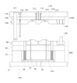
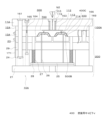
ここで、図3に示すように、型締めによって、成形品用固定側金型100Bの成形品用固定側型板13Bに可動側金型200の可動側型板23が当接し、また、可動側型板23との当接面側とは反対面側で成形品用固定側型板13Bに成形品用ストリッパープレート12Bが当接し、更に、成形品用固定側型板13Bとの当接側とは反対面側で成形品用ストリッパープレート12Bに成形品用固定側取付板11Bが当接した状態とする。これにより、成形品用ストリッパープレート12B及び成形品用固定側型板13Bの間に樹脂の通路としてのランナー112が形成され、また、成形品用固定側型板13B及び可動側型板23の間のパーティング面300が閉じて樹脂成形品500B用の成形品用キャビティ800が形成される。
To explain in more detail below, first, in the primary mold clamping process, the movable side mold plate 23 of the movable side mold 200 is moved so as to face the fixed side mold plate 13B for molded products of the fixed side mold 100B for molded products, and the movable side mold 200 and the fixed side mold 100B for molded products are clamped by facing each other.
3, the movable mold plate 23 of the movable mold 200 is abutted against the fixed mold plate 13B of the fixed mold 100B, the stripper plate 12B is abutted against the fixed mold plate 13B on the opposite side to the abutment side with the movable mold plate 23, and the fixed attachment plate 11B is abutted against the stripper plate 12B on the opposite side to the abutment side with the fixed mold plate 13B. As a result, a runner 112 is formed as a resin passage between the stripper plate 12B and the fixed mold plate 13B, and the parting surface 300 between the fixed mold plate 13B and the movable mold plate 23 is closed to form a cavity 800 for the resin molded product 500B.

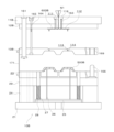
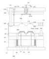
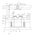
この状態で、射出工程として、成形品用固定側取付板11Bに取付けられたロケートリング(図示せず)にセットされた射出機のシリンダの先端に設けられたノズルN1から溶融樹脂が所定の射出圧(例えば、30MPa以上)で射出されると、図4に示されるように、射出された溶融樹脂は、成形品用固定側金型100Bの成形品用固定側取付板11B及び成形品用ストリッパープレート12Bに設けられたスプルーブッシュ119の1次スプルー111に圧入され、1次スプルー11から成形品用ストリッパープレート12B及び成形用固定側型板13Bの間に設けられたランナー112に流れて、更にランナー112から成形品用固定側型板13Bに設けた2次スプルー113に流れ込んで、その先端部に設けたピンゲート114を通って、成形品用固定側型板13Bのキャビティ形成面310に形成されたピンゲート口から、成形品用固定側型板13B及び可動側型板23の間の成形品用キャビティ800に充填される。
そして、成形工程として、成形品用キャビティ800に充填された溶融樹脂に所定の圧力をかけると共に、溶融樹脂を冷却して固化し、樹脂成形品500Bとする。
In this state, in the injection process, molten resin is injected at a predetermined injection pressure (e.g., 30 MPa or more) from a nozzle N1 provided at the tip of a cylinder of an injector set in a locating ring (not shown) attached to the molded product fixed side mounting plate 11B. As shown in FIG. 4, the injected molten resin is forced into the primary sprue 111 of the sprue bushing 119 provided on the molded product fixed side mounting plate 11B of the molded product fixed side die 100B and the molded product stripper plate 12B. The mixture flows from the primary sprue 11 into a runner 112 provided between the stripper plate 12B for the molded product and the fixed side mold plate 13B for molding, and further flows from the runner 112 into a secondary sprue 113 provided on the fixed side mold plate 13B for the molded product, passes through a pin gate 114 provided at its tip, and is filled into the cavity 800 for the molded product between the fixed side mold plate 13B for the molded product and the movable side mold plate 23 from the pin gate opening formed on the cavity forming surface 310 of the fixed side mold plate 13B for the molded product.
Then, in the molding process, a predetermined pressure is applied to the molten resin filled in the molded product cavity 800, and the molten resin is cooled and solidified to form the resin molded product 500B.

その後、1次型開き工程において、可動側金型200及び成形品用固定側金型100Bの型開きを行う。なお、可動側金型200及び成形品用固定側金型100Bの型締め及び型開き方向は、可動側金型200の動作方向が溶融樹脂の射出方向と同一である。 Then, in the first mold opening process, the movable mold 200 and the fixed mold for molded product 100B are opened. Note that the direction of clamping and opening the movable mold 200 and the fixed mold for molded product 100B is the same as the direction of injection of the molten resin when the movable mold 200 is in motion.

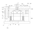
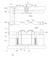
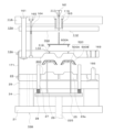
この型開き工程では、図5に示されるように、図示しない型締め装置の可動盤の動きにより可動側金型200を成形品用固定側取付板11B側から離間する方向に移動させると、プラーボルト164による接合力の作用によって、即ち、成形品用固定側型板13B及び成形品用ストリッパープレート12Bに配設されているプラーボルト164を軸としてコイルスプリング(図示せず)が型締め状態において圧縮されて挿置されて、成形品用固定側型板13B及び成形品用ストリッパープレート12Bを開く方向に付勢していることによってコイルスプリングの反発力により、可動側金型200の可動側型板23に対し成形品用固定側型板13Bが当接状態を保ったまま、可動側金型200が成形品用固定側型板13Bと共に移動し、成形品用固定側型板13Bと成形品用ストリッパープレート12Bとの間が開いて分離する。 In this mold opening process, as shown in FIG. 5, when the movable platen of the mold clamping device (not shown) moves the movable mold 200 in a direction away from the molded product fixed side mounting plate 11B, the coil spring (not shown) is compressed and inserted in the mold clamping state with the puller bolt 164 as an axis, which is arranged on the molded product fixed side mold plate 13B and the molded product stripper plate 12B, and biases the molded product fixed side mold plate 13B and the molded product stripper plate 12B in the direction of opening. Due to the repulsive force of the coil spring, the movable mold 200 moves together with the molded product fixed side mold plate 13B while keeping the molded product fixed side mold plate 13B in contact with the movable side mold plate 23 of the movable mold 200, and the gap between the molded product fixed side mold plate 13B and the molded product stripper plate 12B opens and they are separated.

このとき、スプルー111,113及びランナー112に残留し固化したスプルー・ランナー樹脂600Bは、断面積が最小であって最弱箇所であるピンゲート114のゲート口付近で樹脂成形品500Bから分離することになる。即ち、ランナー112の樹脂600Bはランナーロックピン163により固持されているので、成形品用固定側型板13Bと成形品用ストリッパープレート12Bの間が開放されるときに、2次スプルー113の先端部に形成されたピンゲート114にある樹脂が引っ張られ、ピンゲート114が2次スプルー113よりも細く形成されていることにより、そこが強度的に最も弱く、このゲート口付近で樹脂が破断されることにより、ゲートカットされる。 At this time, the sprue/runner resin 600B remaining in the sprues 111, 113 and runner 112 and solidified will separate from the resin molded product 500B near the gate opening of the pin gate 114, which has the smallest cross-sectional area and is the weakest point. That is, since the resin 600B in the runner 112 is held by the runner lock pin 163, when the space between the fixed side mold plate for molded products 13B and the stripper plate for molded products 12B is opened, the resin at the pin gate 114 formed at the tip of the secondary sprue 113 is pulled, and since the pin gate 114 is formed thinner than the secondary sprue 113, this is the weakest point in terms of strength, and the resin breaks near this gate opening, causing the gate to be cut.

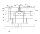
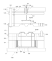
更に、可動側金型200が成形品用固定側取付板11B側とは反対側に移動する型開きが進むと、図6に示されるように、プラーボルト164のボルトヘッドに成形用固定側型板13Bが当接して成形用固定側型板13Bは停止するが、即ち、プラーボルト164により成形品用固定側型板13Bの移動が規制されるが、可動側型板23側は、更に、成形品用固定側取付板11B側と離れる方向に移動し続けることで成形品用固定側型板13Bと分離する。即ち、成形品用固定側型板13Bと可動側型板23との間のパーティング面300が開く。なお、ランナーロックピン163が成形品用固定側型板13Bに形成されているランナー112に対しアンダーカット状に形成されている先端部で係止していることにより、成形品用ストリッパープレート12Bが成形品用固定側取付板11B側に保持されているのに対し、パーティング面300に何ら付勢力が生じていないことにより可動側金型200の後退の動きに伴い、成形品用固定側型板13Bと可動側型板23との間が開放されることになる。このとき、樹脂成形品500Bは、可動側金型200の可動側型板23側に残存する。 Furthermore, as the mold opening progresses with the movable mold 200 moving in the direction opposite to the molded product fixed side mounting plate 11B, the molding fixed side mold plate 13B comes into contact with the bolt head of the puller bolt 164 and stops, as shown in Figure 6. In other words, the movement of the molded product fixed side mold plate 13B is restricted by the puller bolt 164, but the movable side mold plate 23 continues to move in a direction away from the molded product fixed side mounting plate 11B, thereby separating from the molded product fixed side mold plate 13B. In other words, the parting surface 300 between the molded product fixed side mold plate 13B and the movable side mold plate 23 opens. In addition, since the runner lock pin 163 is engaged with the runner 112 formed on the fixed side mold plate 13B at the tip portion formed in an undercut shape, the stripper plate 12B for molded products is held on the side of the fixed side mounting plate 11B for molded products, while no biasing force is generated on the parting surface 300, and as the movable side mold 200 moves backward, the space between the fixed side mold plate 13B for molded products and the movable side mold plate 23 is opened. At this time, the resin molded product 500B remains on the movable side mold plate 23 side of the movable side mold 200.

そして、可動側金型200が、更に移動して型開きが進み、成形品用固定側型板13Bと可動側型板23との間の引張りリンク171により制限される開きが最大となると、以後、引張リンク171を介して、成形品用固定側型板13Bが型開き方向に牽引される。そして、成形品用固定側型板13Bと成形品用ストリッパープレート12Bとの間のプラーボルト164により制限される開きが最大となると、成形品用固定側型板13Bがプラーボルト164を引っ張ることで、プラーボルト164を介して作用する牽引力により、成形品用ストリッパープレート12Bが成形用固定側取付板11から離れる方向に移動し、図7に示されるように、成形品用ストリッパープレート12Bと成形品用固定側取付板11Bが分離して、成形品用ストリッパープレート12B及び成形品用固定側取付板11Bの間がストップボルト165によって規制される所定間隔だけ開放される。 Then, the movable mold 200 moves further to proceed with mold opening, and when the opening restricted by the tension link 171 between the fixed mold plate 13B for molded products and the movable mold plate 23 becomes maximum, the fixed mold plate 13B for molded products is pulled in the mold opening direction via the tension link 171. When the opening restricted by the puller bolt 164 between the fixed mold plate 13B for molded products and the stripper plate 12B for molded products becomes maximum, the fixed mold plate 13B for molded products pulls the puller bolt 164, and the stripper plate 12B for molded products moves in a direction away from the fixed mounting plate 11 for molded products due to the pulling force acting via the puller bolt 164, and as shown in FIG. 7, the stripper plate 12B for molded products and the fixed mounting plate 11B for molded products are separated, and the gap between the stripper plate 12B for molded products and the fixed mounting plate 11B for molded products is opened by a predetermined distance restricted by the stop bolt 165.

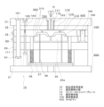
このとき、図8に示されるように、1次スプルー111、ランナー112、2次スプルー113、及びピンゲート114内に残留して固まったスプルー・ランナー樹脂600Bは、断面積が最小であって最弱箇所である射出ノズルN1の噴射口の付近で、射出ノズルN1に残った樹脂から分離する。即ち、成形品用固定側取付板11Bと成形品用ストリッパープレート12Bの間が開放されるときに、スプルー・ランナー樹脂600Bが射出ノズルN1に残った樹脂と引き離され、また、スプルー・ランナー樹脂600に作用する成形品用ストリッパープレート12Bからの押出力によりスプルー・ランナー樹脂600Bに対するランナーロックピン163のランナーロック部の係合が解消されて、スプルー・ランナー樹脂600Bがロックピン163から引き離され、成形品用ストリッパープレート12B側にはりついていた(食いついていた)スプルー・ランナー樹脂600が落下して成形品用固定側金型100Bから外れる。なお、次回の樹脂成形品500Bを形成する成形品用樹脂の射出工程が開始される際には、再び、成形品用固定側金型100Bと可動側金型200との間で型締めが行なわれる。即ち、可動側金型200が成形品用固定側金型100B側に移動し、成形品用固定側取付板11B、成形品用ストリッパープレート12B、成形品用固定側型板13B、及び可動側型板23の相互間が閉じられ型閉じした型締め状態に戻る。 At this time, as shown in FIG. 8, the sprue/runner resin 600B remaining and solidified in the primary sprue 111, runner 112, secondary sprue 113, and pin gate 114 separates from the resin remaining in the injection nozzle N1 near the nozzle tip of the injection nozzle N1, which has the smallest cross-sectional area and is the weakest point. That is, when the space between the fixed attachment plate 11B for molded products and the stripper plate 12B for molded products is opened, the sprue/runner resin 600B is separated from the resin remaining in the injection nozzle N1, and the runner locking portion of the runner lock pin 163 is disengaged from the sprue/runner resin 600B by the pushing force from the stripper plate 12B for molded products acting on the sprue/runner resin 600B, so that the sprue/runner resin 600B is separated from the lock pin 163, and the sprue/runner resin 600 that has been stuck (bitten) to the stripper plate 12B for molded products falls and is removed from the fixed metal mold 100B for molded products. When the injection process of the resin for molded products to form the next resin molded product 500B is started, the fixed metal mold 100B for molded products and the movable metal mold 200 are clamped again. That is, the movable mold 200 moves toward the fixed mold 100B for molded products, and the spaces between the fixed attachment plate 11B for molded products, the stripper plate 12B for molded products, the fixed mold plate 13B for molded products, and the movable mold plate 23 are closed, returning to a mold-closed clamped state.

次に、可動側金型200と成形品用固定側金型100Bとの離間で、成形品用固定側金型100Bから樹脂成形品500Bが離型し、可動側金型200のキャビティ形成面310に樹脂成形品500Bが保持された状態で、切替工程において、可動側金型200に対向させる固定側金型を成形品用固定側金型100Bから塗装用固定側金型100Aに切り替える移動を行う。
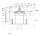
このときの切り替え手段としては、金型をスライドさせるダイスライドインジェクション方式(DSI方式)や、型開閉方向を回転軸とする金型取付板に取り付けられた複数の金型を回転させるダイロータリーインジェクション方式(DRI方式)や、固定盤と可動盤との間で複数の金型を型開閉方向と垂直な方向に回転させる回転盤方式等の金型移動手段によって、可動側金型200に組み合わせる固定側金型を成形品用固定側金型100Bから塗装用固定側金型100Aに切り替えることができる。例えば、可動側金型200において樹脂成形品500Bが保持された状態の可動側型板13が塗装用固定側金型100Aの塗装用固定側型板13Aに対向するように移動され、図9に示すように、可動側金型200及び塗装用固定側金型100Aで型内塗装用金型10Aを構成する。そして、2次型締め工程として、可動側金型200及び塗装用固定側金型100Aを対向させた状態で型締めする。
Next, as the movable side mold 200 and the fixed side mold for molded product 100B are separated, the resin molded product 500B is released from the fixed side mold for molded product 100B, and while the resin molded product 500B is held on the cavity forming surface 310 of the movable side mold 200, a movement is made in which the fixed side mold that faces the movable side mold 200 is switched from the fixed side mold for molded product 100B to the fixed side mold for painting 100A.
The switching means at this time can be a die slide injection method (DSI method) in which a die is slid, a die rotary injection method (DRI method) in which a plurality of dies attached to a die mounting plate are rotated with the die opening/closing direction as a rotation axis, or a rotary plate method in which a plurality of dies are rotated in a direction perpendicular to the die opening/closing direction between a fixed platen and a movable platen, and the like, and the fixed side die to be combined with the movable side die 200 can be switched from the fixed side die 100B for molded products to the fixed side die 100A for painting by using such die moving means. For example, the movable side mold plate 13 in the movable side die 200, in which the resin molded product 500B is held, is moved to face the fixed side die 13A for painting of the fixed side die 100A for painting, and the movable side die 200 and the fixed side die 100A for painting constitute the in-mold painting die 10A as shown in FIG. Then, as a secondary mold clamping process, the movable side die 200 and the fixed side die 100A for painting are clamped in a state in which they are opposed to each other.

塗装用金型10Aを構成する可動側金型200及び塗装用固定側金型100Aにおいても、図10に示すように、型締めによって、塗装用固定側金型100Aの塗装用固定側型板13Aに可動側金型200の可動側型板23が当接し、また、可動側型板23との当接面側とは反対面側で塗装用固定側型板13Aに塗装用ストリッパープレート12Aが当接し、更に、塗装用固定側型板13Aとの当接側とは反対面側で塗装用ストリッパープレート12に塗装用固定側取付板11Aが当接した状態とする。これにより、塗装用ストリッパープレート12A及び塗装用固定側型板13Aの間に2液混合型の熱硬化性樹脂からなる塗料の通路としてのランナー112が形成され、また、塗装用固定側型板13A及び可動側型板23の間のパーティング面300が閉じて塗装用キャビティ400が形成される。 As shown in FIG. 10, in the movable side mold 200 and the fixed side mold 100A for painting that constitute the paint mold 10A, the movable side mold plate 23 of the movable side mold 200 is abutted against the fixed side mold plate 13A for painting of the fixed side mold 100A, the paint stripper plate 12A is abutted against the fixed side mold plate 13A for painting on the side opposite to the side of abutment with the movable side mold plate 23, and the fixed side mounting plate 11A for painting is abutted against the stripper plate 12 on the side opposite to the side of abutment with the fixed side mold plate 13A for painting. As a result, a runner 112 is formed between the paint stripper plate 12A and the fixed side mold plate 13A for painting as a passage for paint made of a two-component thermosetting resin, and the parting surface 300 between the fixed side mold plate 13A for painting and the movable side mold plate 23 is closed to form a paint cavity 400.

ここで、本実施の形態1においては、可動側金型200の可動側型板23のキャビティ形成面310には、樹脂成形品500Bが保持された状態にあるため、塗装用固定側金型100B及び可動側金型200が型閉じされた状態では、塗装用固定側型板13B及び可動側型板23間で形成される塗装用キャビティ400内に樹脂成形品500Bが配設し、樹脂成形品500Bと、可動側型板23に対面する塗装用可動側型板13Bのキャビティ形成面310との間にクリアランス400Cを設けている。 In this embodiment 1, the resin molded product 500B is held on the cavity forming surface 310 of the movable side mold plate 23 of the movable side mold 200, so when the painting fixed side mold 100B and the movable side mold 200 are closed, the resin molded product 500B is disposed in the painting cavity 400 formed between the painting fixed side mold plate 13B and the movable side mold plate 23, and a clearance 400C is provided between the resin molded product 500B and the cavity forming surface 310 of the painting movable side mold plate 13B facing the movable side mold plate 23.

このように塗装用金型10Aを構成する塗装用固定側金型100A及び可動側金型200が型閉じされ、樹脂成形品500Bと、可動側型板23に対面する塗装用可動側型板13Bのキャビティ形成面310との間にクリアランス400Cを形成した状態で、射出注入工程において、塗装用固定側取付板11A側にセットされた注入機のシリンダの先端に設けられたノズルN2から2液混合型の熱硬化性樹脂の塗料が所定の注入圧(例えば、100~200bar、好ましくは、120~180bar)及び温度(例えば、60~90℃、好ましくは、60~70℃)で射出注入される。
このとき型閉じされた可動側金型200及び塗装用固定側金型100Aは2液混合型の熱硬化性樹脂が充分に硬化する温度(例えば、20~150℃、好ましくは、70~90℃の金型温度)に予め加熱され、その状態の可動側金型200及び塗装用固定側金型100Aに対し、塗料が射出注入される。
なお、図示しない注入機は駆動装置によって駆動され、樹脂注入口に、例えば、バルブが取りつけられており、2液が混合された熱硬化性樹脂の射出注入量の調節を可能としている。樹脂注入機は、例えば、樹脂を計量する計量シリンダ、開閉弁を有し樹脂を注入するインジェクタ、計量や開閉弁を制御するコントローラ、樹脂タンク等を備えている。樹脂の射出注入時には、インジェクタが開き、計量シリンダで計量された樹脂がインジェクタから吐出される。また、一般的には、注入機内での樹脂の硬化を防止するための樹脂循環・冷却機構を備え、樹脂タンクに投入された樹脂が循環されている。
In this manner, the fixed side painting mold 100A and the movable side mold 200 constituting the painting mold 10A are closed, and a clearance 400C is formed between the resin molded product 500B and the cavity forming surface 310 of the movable side painting mold plate 13B facing the movable side mold plate 23. In this state, in the injection process, a two-component mixed thermosetting resin paint is injected at a predetermined injection pressure (e.g., 100 to 200 bar, preferably 120 to 180 bar) and temperature (e.g., 60 to 90°C, preferably 60 to 70°C) from the nozzle N2 provided at the tip of the cylinder of the injection machine set on the side of the fixed side painting attachment plate 11A.
At this time, the closed movable mold 200 and the fixed mold for painting 100A are preheated to a temperature at which the two-component mixed thermosetting resin can be sufficiently hardened (e.g., a mold temperature of 20 to 150°C, preferably 70 to 90°C), and paint is injected into the movable mold 200 and the fixed mold for painting 100A in this state.
The injection machine (not shown) is driven by a drive device, and a valve, for example, is attached to the resin injection port, making it possible to adjust the injection amount of the thermosetting resin mixed with two liquids. The resin injection machine includes, for example, a measuring cylinder for measuring the resin, an injector having an on-off valve for injecting the resin, a controller for controlling the measurement and the on-off valve, and a resin tank. When injecting the resin, the injector opens, and the resin measured by the measuring cylinder is discharged from the injector. In addition, the injection machine generally includes a resin circulation/cooling mechanism for preventing the resin from hardening in the injection machine, and the resin put into the resin tank is circulated.

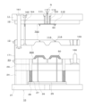
型閉じされた可動側金型200及び塗装用固定側金型100Aに対し2液混合型の熱硬化性樹脂からなる塗料が射出注入されると、図11に示されるように、射出注入された塗料は、塗装用固定側金型100Aの塗装用固定側取付板11A及び塗装用ストリッパープレート12Aに設けられたスプルーブッシュ119の1次スプルー111に注入され、1次スプルー111から塗装用ストリッパープレート12A及び塗装用固定側型板13Aの間に設けられたランナー112に流れて、更に、ランナー112から塗装用固定側型板13Aに設けた2次スプルー113に流れ込んで、その先端部に設けたピンゲート114を通って、塗装用固定側型板13Aのキャビティ形成面310に形成されたピンゲート口から、塗装用キャビティ400における樹脂成形品500Bと成形用固定側型板13Aのキャビティ形成面310との間のクリアランス400Cに充填される。 When paint made of a two-liquid mixed thermosetting resin is injected into the closed movable mold 200 and the fixed mold for painting 100A, as shown in FIG. 11, the injected paint is injected into the primary sprue 111 of the sprue bush 119 provided on the fixed mounting plate for painting 11A and the stripper plate for painting 12A of the fixed mold for painting 100A, and is then poured from the primary sprue 111 to the stripper plate for painting 12A and the fixed mold for painting 13A, and then from the runner 112 into the secondary sprue 113 on the fixed side painting mold plate 13A, passing through the pin gate 114 at its tip, and filling the clearance 400C between the resin molded product 500B in the painting cavity 400 and the cavity forming surface 310 of the fixed side molding plate 13A through the pin gate opening formed on the cavity forming surface 310 of the fixed side painting mold plate 13A.

そして、塗装成形工程として、その状態で所定時間(例えば、10秒~600秒)保持することで2液混合型の熱硬化性樹脂の塗料を硬化させる。即ち、クリアランス400Cへの塗料の充填で樹脂成形品500Bの表面に被覆された塗料が硬化し成形されることで樹脂成形品500Bの表面に塗膜500Aが形成された塗装樹脂成形品500となる。なお、塗膜500Aの厚みは、硬化厚みで、例えば、0.1mm~10mm、好ましくは、0.1mm~6mmとなるように設定される。 Then, in the paint forming process, the two-component thermosetting resin paint is hardened by holding the paint in this state for a predetermined time (for example, 10 to 600 seconds). That is, the paint that covers the surface of the resin molded product 500B when the paint is filled into the clearance 400C is hardened and molded to form the coated resin molded product 500 in which the coating film 500A is formed on the surface of the resin molded product 500B. The thickness of the coating film 500A is set to, for example, 0.1 to 10 mm, preferably 0.1 to 6 mm, in terms of the hardened thickness.

特に、本実施の形態1では、塗装用固定側金型100A及び可動側金型200を型締めして塗装用固定側金型100Aの塗装用固定側型板13Aと可動側金型200の可動側型板23のパーティング面300を合わせた当接状態で、樹脂成形品500Bと成形用固定側型板13Aのキャビティ形成面310との間で塗料が充填されるクリアランス400Cを形成して塗装用固定側金型100A及び可動側金型200の型締め状態で塗料をクリアランス400Cに充填するうえ、塗装用固定側金型100Aの塗装用固定側型板13Aと可動側金型200の可動側型板23の分離面であるパーティング面300の表面粗さRzが0.8μm以下、好ましくは、0.6μm以下、より好ましくは、0.4μm以下、更に好ましくは、0.2μm以下であることにより、塗装用固定側金型100Aの塗装用固定側型板13Aと可動側金型200の可動側型板23の当接面であるパーティング面300が高精度な平滑面となりメタルタッチすることで、ポリウレタンやシリコーン等の2液混合型の熱硬化性樹脂からなる塗料の粘性が低くて流動性が高くとも、塗装用固定側金型100Aの塗装用固定側型板13Aと可動側金型200の可動側型板23の当接面であるパーティング面300に塗料が漏出し難く、バリ不良を生じさせ難いものである。 In particular, in this embodiment 1, when the fixed-side paint mold 100A and the movable-side mold 200 are clamped together and the parting surface 300 of the fixed-side paint mold plate 13A of the fixed-side paint mold 100A and the movable-side paint mold plate 23 of the movable-side mold 200 are brought into contact with each other, a clearance 400C is formed between the resin molded product 500B and the cavity forming surface 310 of the fixed-side paint mold plate 13A, and paint is filled into the clearance 400C in the clamped state of the fixed-side paint mold 100A and the movable-side paint mold plate 23 of the movable-side mold 200. By setting z to 0.8 μm or less, preferably 0.6 μm or less, more preferably 0.4 μm or less, and even more preferably 0.2 μm or less, the parting surface 300, which is the contact surface between the fixed-side painting mold plate 13A of the fixed-side painting mold 100A and the movable-side mold plate 23 of the movable-side mold 200, becomes a highly accurate smooth surface and has a metal touch. Even if the paint made of a two-liquid mixture type thermosetting resin such as polyurethane or silicone has low viscosity and high fluidity, the paint is unlikely to leak onto the parting surface 300, which is the contact surface between the fixed-side painting mold plate 13A of the fixed-side painting mold 100A and the movable-side mold plate 23 of the movable-side mold 200, and burrs are unlikely to occur.

また、ピンゲート114を通して塗装用キャビティ400内の樹脂成形品500Bとキャビティ形成面310との間のクリアランス400Cに2液混合型の熱硬化性樹脂からなる塗料を注入するものであるから、充填不良が生じ難く、薄い塗膜500Aを形成できる。当然、高い注入圧力を要しないから塗料の漏れ防止にもなる。 In addition, because the paint is made of a two-part thermosetting resin mixture and is injected through the pin gate 114 into the clearance 400C between the resin molded product 500B in the coating cavity 400 and the cavity forming surface 310, poor filling is unlikely to occur and a thin coating film 500A can be formed. Naturally, since high injection pressure is not required, paint leakage is also prevented.

加えて、塗装用固定側金型100Aのランナー112は、塗装用固定側型板13A及び塗装用ストリッパープレート12Aの間に形成され、塗装用固定側型板13A及び塗装用ストリッパープレート12Aの分割面700の表面粗さRzが0.8μm以下、好ましくは、0.6μm以下、より好ましくは、0.4μm以下、更に好ましくは、0.2μm以下であるから、粘性が低い2液混合型の熱硬化性樹脂からなる塗料がランナー112に注入されても、塗装用固定側型板13A及び塗装用ストリッパープレート12Aが当接する合わせ面への塗料の漏れ(侵入)も防止できる。よって、漏出し付着した樹脂を除去する作業を軽減でき、成形サイクルを良くできる。 In addition, the runner 112 of the fixed side paint mold 100A is formed between the fixed side paint mold plate 13A and the stripper plate 12A, and the surface roughness Rz of the parting surface 700 of the fixed side paint mold plate 13A and the stripper plate 12A is 0.8 μm or less, preferably 0.6 μm or less, more preferably 0.4 μm or less, and even more preferably 0.2 μm or less. Therefore, even if paint made of a low-viscosity two-liquid mixed type thermosetting resin is injected into the runner 112, the paint can be prevented from leaking (penetrating) into the mating surface where the fixed side paint mold plate 13A and the stripper plate 12A come into contact. This reduces the work of removing the leaked and attached resin, and improves the molding cycle.

そして、2液混合型の熱硬化性樹脂の塗料が充分に加熱されて硬化したら、必要に応じ、所定温度まで塗装用金型10Aを冷却した後、塗装用キャビティ400内の塗装樹脂成形品500を取り出すために、二次型開き工程として、可動側金型200及び塗装用固定側金型100Aの型開きを行う。なお、型内塗装用金型10Aの型締め及び型開き方向も、可動側金型200の動作方向が2液混合型の熱硬化性樹脂からなる塗料の射出注入方向と同一である。 Then, when the two-component thermosetting resin paint is sufficiently heated and hardened, the paint mold 10A is cooled to a predetermined temperature as necessary, and then the movable mold 200 and the fixed mold 100A for painting are opened as a secondary mold opening process in order to remove the painted resin molded product 500 from the paint cavity 400. The clamping and opening directions of the in-mold paint mold 10A are also the same as the operating direction of the movable mold 200, which is the same as the injection direction of the paint made of two-component thermosetting resin.

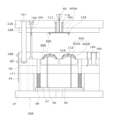
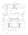
二次型開き工程では、図12に示されるように、成形品用金型10Bのときと同様に、図示しない型締め装置の可動盤の動きにより可動側金型200を塗装用固定側取付板11A側とは反対側に移動させると、プラーボルト164による接合力の作用によって、即ち、塗装用固定側型板13A及び塗装用ストリッパープレート12Aに配設されているプラーボルト164を軸としてコイルスプリング(図示せず)が型締め状態において圧縮されて挿置されて、塗装用固定側型板13A及び塗装用ストリッパープレート12Aを開く方向に付勢していることによってコイルスプリングの反発力により、可動側金型200の可動側型板23に対し塗装用固定側型板13Aが当接状態を保ったまま、可動側金型200が塗装用固定側型板13Aと共に移動し、塗装用固定側型板13Aと塗装用ストリッパープレート12Aとの間が開いて分離する。 In the secondary mold opening process, as shown in FIG. 12, in the same way as with the mold 10B for molded products, the movable mold 200 is moved to the opposite side from the side of the fixed mounting plate 11A by the movement of the movable plate of the mold clamping device (not shown). The coil spring (not shown) is compressed and inserted in the mold clamping state with the puller bolt 164 arranged on the fixed mold plate 13A for painting and the stripper plate 12A as the axis by the action of the joining force of the puller bolt 164, and the fixed mold plate 13A for painting and the stripper plate 12A for painting are biased in the direction of opening. The repulsive force of the coil spring causes the movable mold 200 to move together with the fixed mold plate 13A for painting while keeping the fixed mold plate 13A in contact with the movable mold plate 23 of the movable mold 200. The gap between the fixed mold plate 13A for painting and the stripper plate 12A opens and they are separated.

このとき、スプルー111,113及びランナー112内で残留して硬化されているスプルー・ランナー樹脂600Aは、断面積が最小であって最弱箇所であるピンゲート114のゲート口付近で塗装樹脂成形品500から分離することになる。即ち、ランナー112の樹脂600Aはランナーロックピン163により固持されているので、塗装用固定側型板13Aと塗装用ストリッパープレート12Aの間が開放されるときに、2次スプルー113の先端部に形成されたピンゲート114にある樹脂が引っ張られ、ピンゲート114が2次スプルー113よりも細く形成されていることにより、そこが強度的に最も弱く、このゲート口付近で樹脂が破断されることにより、ゲートカットされる。 At this time, the sprue/runner resin 600A remaining and hardened in the sprues 111, 113 and runner 112 will separate from the painted resin molded product 500 near the gate opening of the pin gate 114, which has the smallest cross-sectional area and is the weakest point. That is, since the resin 600A in the runner 112 is held by the runner lock pin 163, when the space between the painting fixed side template 13A and the painting stripper plate 12A is opened, the resin in the pin gate 114 formed at the tip of the secondary sprue 113 is pulled, and since the pin gate 114 is formed thinner than the secondary sprue 113, this is the weakest point in terms of strength, and the resin breaks near this gate opening, causing the gate to be cut.

更に、可動側金型200が塗装用固定側取付板11A側とは反対側に移動する型開きが進むと、図13に示されるように、プラーボルト164のボルトヘッドに塗装用固定側型板13Aが当接して塗装用固定側型板13Aは停止するが、即ち、プラーボルト164により塗装用固定側型板13Aの移動が規制されるが、可動側型板23は、更に、塗装用固定側取付板11A側と離れる方向に移動し続けることで塗装用固定側型板13Aと分離する。即ち、塗装用固定側型板13Aと可動側型板23との間のパーティング面300が開く。なお、ランナーロックピン163が塗装用固定側型板13Aに形成されているランナー112に対しアンダーカット状に形成されている先端部で係止していることにより、塗装用ストリッパープレート12Aが塗装用固定側取付板11A側に保持されているのに対し、パーティング面300に何ら付勢力が生じていないことにより可動側金型200の後退の動きに伴い、塗装用固定側型板13Aと可動側型板23との間が開放されることになる。
このとき、塗装樹脂成形品500は、塗装用固定側型板13Aから離型し、可動側金型200の可動側型板23側に残存する。
13, when the movable die 200 moves in the direction opposite to the painting fixed side attachment plate 11A, the painting fixed side template 13A comes into contact with the bolt head of the puller bolt 164 and stops, i.e., the movement of the painting fixed side template 13A is restricted by the puller bolt 164, but the movable side template 23 continues to move in the direction away from the painting fixed side attachment plate 11A and separates from the painting fixed side template 13A. That is, the parting surface 300 between the painting fixed side template 13A and the movable side template 23 opens. Furthermore, since the runner lock pin 163 is engaged with the runner 112 formed on the fixed side painting template 13A at its tip portion which is formed in an undercut shape, the painting stripper plate 12A is held on the side of the fixed side painting mounting plate 11A, whereas no biasing force is generated on the parting surface 300, as the movable side die 200 moves backward, the gap between the fixed side painting template 13A and the movable side template 23 is opened.
At this time, the coated resin molded product 500 is released from the coating fixed mold plate 13 A and remains on the movable mold plate 23 side of the movable metal mold 200 .

そして、可動側金型200が、更に移動して型開きが進み、塗装用固定側型板13Aと可動側型板23との間の引張りリンク171により制限される開きが最大となると、以後、引張リンク171を介して、塗装用固定側型板13Aが型開き方向に牽引される。そして、塗装用固定側型板13Aと塗装用ストリッパープレート12Aとの間のプラーボルト164により制限される開きが最大となると、塗装用固定側型板13Aがプラーボルト164を引っ張ることで、プラーボルト164を介して作用する牽引力により、塗装用ストリッパープレート12Aが塗装用固定側取付板11Aから離れる方向に移動し、図14に示されるように、塗装用ストリッパープレート12Aと塗装用固定側取付板11Aが分離して、塗装用ストリッパープレート12A及び塗装用固定側取付板11Aの間がストップボルト165によって規制される所定間隔だけ開放される。 Then, the movable side mold 200 moves further to proceed with mold opening, and when the opening restricted by the tension link 171 between the painting fixed side mold plate 13A and the movable side mold plate 23 becomes maximum, the painting fixed side mold plate 13A is pulled in the mold opening direction via the tension link 171. When the opening restricted by the puller bolt 164 between the painting fixed side mold plate 13A and the painting stripper plate 12A becomes maximum, the painting fixed side mold plate 13A pulls the puller bolt 164, and the painting stripper plate 12A moves in a direction away from the painting fixed side mounting plate 11A due to the pulling force acting via the puller bolt 164, and as shown in FIG. 14, the painting stripper plate 12A and the painting fixed side mounting plate 11A are separated, and the paint stripper plate 12A and the painting fixed side mounting plate 11A are opened by a predetermined distance restricted by the stop bolt 165.

このとき、図15に示されるように、1次スプルー111、ランナー112、2次スプルー113、及びピンゲート114内に残留して硬化したスプルー・ランナー樹脂600Aは、断面積が最小であって最弱箇所である射出注入ノズルN2の噴射口の付近で、射出注入ノズルN2に残った樹脂から分離する。即ち、塗装用固定側取付板11Aと塗装用ストリッパープレート12Aの間が開放されるときに、スプルー・ランナー樹脂600Aが射出注入ノズルN2に残った樹脂と引き離され、また、スプルー・ランナー樹脂600Aに作用する塗装用ストリッパープレート12Aからの押出力によりスプルー・ランナー樹脂600Aに対するランナーロックピン163のランナーロック部の係合が解消されて、スプルー・ランナー樹脂600Aがロックピン163から引き離され、塗装用ストリッパープレート12A側にはりついていた(食いついていた)スプルー・ランナー樹脂600Aが落下して塗装用固定側金型100Aから外れる。 At this time, as shown in FIG. 15, the sprue/runner resin 600A remaining and hardened in the primary sprue 111, runner 112, secondary sprue 113, and pin gate 114 separates from the resin remaining in the injection nozzle N2 near the nozzle tip of the injection nozzle N2, which has the smallest cross-sectional area and is the weakest point. That is, when the space between the paint stationary side mounting plate 11A and the paint stripper plate 12A is opened, the sprue/runner resin 600A is pulled away from the resin remaining in the injection nozzle N2, and the extrusion force from the paint stripper plate 12A acting on the sprue/runner resin 600A disengages the runner lock portion of the runner lock pin 163 from the sprue/runner resin 600A, pulling the sprue/runner resin 600A away from the lock pin 163, and the sprue/runner resin 600A that was stuck (biting) to the paint stripper plate 12A side falls and comes off the paint stationary side mold 100A.

そして、射出成形装置のエジェクターロッド225の作動を利用してエジェクタープレート25が塗装用固定側金型100A側に向かって突き出されることにより、エジェクタープレート25に固設されているエジェクターピン26の先端部が可動側型板23の入れ子23aから突出して、可動側型板23のキャビティ形成面310に残存している塗装樹脂成形品500を押し出す(突き出す)。これにより、塗装樹脂成形品500が可動側型板23の入れ子23aから離れて落下し、回収、或いは、取り出し機により取り出されて回収される。得られた塗装樹脂成形品500は、成形品用金型10B内で成形した樹脂成形品500Bの表面を、樹脂成形品500Bを形成した溶融樹脂の粘度よりも低粘度の2液混合型の熱硬化性樹脂塗料からなる塗膜500Aで被覆したものである。2液混合型の熱硬化性樹脂からなる塗料を樹脂成形品500Bの表面に被覆して形成した塗膜500Aの厚みは、例えば、0.1mm以上、6mm以下である。 Then, by using the operation of the ejector rod 225 of the injection molding device, the ejector plate 25 is pushed toward the side of the fixed side mold 100A for painting, and the tip of the ejector pin 26 fixed to the ejector plate 25 protrudes from the insert 23a of the movable side mold plate 23 and pushes out (projects) the painted resin molded product 500 remaining on the cavity forming surface 310 of the movable side mold plate 23. As a result, the painted resin molded product 500 falls away from the insert 23a of the movable side mold plate 23 and is recovered, or is removed by a removal machine and recovered. The obtained painted resin molded product 500 is a resin molded product 500B molded in the mold for molded product 10B, the surface of which is covered with a coating film 500A made of a two-liquid mixed type thermosetting resin paint having a lower viscosity than the viscosity of the molten resin that formed the resin molded product 500B. The thickness of the coating film 500A formed by coating the surface of the resin molded product 500B with paint made of a two-component thermosetting resin is, for example, 0.1 mm or more and 6 mm or less.

上述したように、本実施の形態1では、樹脂成形品500Bを形成するための成形品用金型10Bにおいても、また、樹脂成形品500Bを塗装するための型内塗装用金型10Aにおいても、型開きにより、可動側金型200が固定側取付板11A,11B側とは反対側に動き出すと、プラーボルト164に設けられているスプリングの力で固定側型板13A,13Bとランナーストリッパープレート12A,12Bとの間が最初に開き、このときランナー112側で固化している樹脂600A,600Bはランナーロックピン163によって固定側(ランナーストリッパープレート12A,12B側)に引きつけられているので、最も弱いピンゲート114のピンゲート口付近で切断される。更に、可動側金型200が動いて型開きが進むと、固定側型板13A,13Bと可動側型板23との間のパーティング面300が開いて、通常、樹脂成形品500Bや塗装樹脂成形品500が固定側型板13A,13Bから離型し、可動側型板23のキャビティ形成面310側に残存する。 As described above, in this embodiment 1, both in the molded product mold 10B for forming the resin molded product 500B and in the in-mold painting mold 10A for painting the resin molded product 500B, when the movable side mold 200 begins to move opposite the fixed side mounting plates 11A, 11B due to mold opening, the space between the fixed side mold plates 13A, 13B and the runner stripper plates 12A, 12B is first opened by the force of the spring provided in the puller bolt 164, and at this time, the resin 600A, 600B that has solidified on the runner 112 side is pulled toward the fixed side (runner stripper plates 12A, 12B side) by the runner lock pin 163, and is therefore cut near the pin gate opening of the weakest pin gate 114. Furthermore, as the movable side mold 200 moves and the mold opening progresses, the parting surface 300 between the fixed side mold plates 13A, 13B and the movable side mold plate 23 opens, and typically the resin molded product 500B or the painted resin molded product 500 is released from the fixed side mold plates 13A, 13B and remains on the cavity forming surface 310 side of the movable side mold plate 23.

更に、固定側型板13A,13Bと可動側型板23の間との開きが引張リンク171によりストロークの制限いっぱいになり、また、固定側型板13A,13Bとランナーストリッパープレート12A,12Bとの間の開きがプラーボルト164によりストロークの制限いっぱいになり、可動側金型200が固定側金型100A,100B側から離れて型開きが進むと、引張リンク171及びプラーボルト164によりランナーストリッパープレート12A,12Bが引っ張られて、ランナーロックピン163とランナー112で固化した樹脂との結合部分が強制的に離され、射出注入ノズルN1,N2の噴射口の付近で射出ノズルN1,N2に残った樹脂と引き離されると、スプルー111,113及びランナー112で固化していたスプルー・ランナー樹脂600A,600Bが落下する。 Furthermore, the gap between the fixed side mold plates 13A, 13B and the movable side mold plate 23 is fully limited by the tension link 171, and the gap between the fixed side mold plates 13A, 13B and the runner stripper plates 12A, 12B is fully limited by the puller bolt 164. When the movable side mold 200 moves away from the fixed side molds 100A, 100B and mold opening proceeds, the runner stripper plates 12A, 12B are pulled by the tension link 171 and the puller bolt 164, and the connection between the runner lock pin 163 and the resin solidified in the runner 112 is forcibly separated. When the resin is separated from the resin remaining in the injection nozzles N1, N2 near the injection nozzles N1, N2, the sprue/runner resin 600A, 600B that had solidified in the sprues 111, 113 and the runner 112 falls.

また、型内塗装用金型10Aでの塗装を完了して、可動側型板23のキャビティ形成面310側に残存している塗装樹脂成形品500は、射出成形装置のエジェクターロッド255の作動を利用してエジェクタープレート25を介しエジェクターピン26によって突き出されて取り出される。
なお、スプルー・ランナー樹脂600Aと塗装樹脂成形品500が離型し型外に取り出された後は、射出成形装置のエジェクターロッド225が引き込むことで、リターンスプリング28の反発力によりエジェクターピン26が軸方向に後退され、突き出し前の元の位置に復帰する。そして、次回の塗装工程が開始される際には、再び、塗装用固定側金型100Aと可動側金型200との間で型締めが行なわれる。即ち、可動側金型200が塗装用固定側金型100A側に移動し、塗装用固定側取付板11A、塗装用ストリッパープレート12A、塗装用固定側型板13A、及び可動側型板23の相互間が閉じられ型閉じした型締め状態に戻る。
In addition, after painting in the in-mold painting metal mold 10A is completed, the painted resin molded product 500 remaining on the cavity forming surface 310 side of the movable side mold plate 23 is ejected and removed by the ejector pin 26 through the ejector plate 25 by utilizing the operation of the ejector rod 255 of the injection molding device.
After the sprue/runner resin 600A and the coated resin molded product 500 are released and taken out of the mold, the ejector rod 225 of the injection molding device is retracted, and the ejector pin 26 is retracted in the axial direction by the repulsive force of the return spring 28, returning to the original position before ejection. Then, when the next painting process is started, the fixed painting mold 100A and the movable mold 200 are clamped again. That is, the movable mold 200 moves to the fixed painting mold 100A side, and the spaces between the fixed painting attachment plate 11A, the stripper plate 12A, the fixed painting mold plate 13A, and the movable mold plate 23 are closed, returning to the mold-closed clamped state.

本実施の形態1の型内塗装用金型10A及び成形品用金型10Bでは、何れも、固定側型板13A,13Bとランナーストリッパープレート12A,12Bと可動側型板23とを有する3プレート構造であり、可動側型板23と固定側型板13A,13Bとの間で(パーティング面で)所定のストロークだけ分離自在で、また、固定側型板13A,13Bとランナーストリッパープレート12A,12Bとの間で所定のストロークだけ分離自在であり、更に、ランナーストリッパープレート12A,12Bも固定側取付板11A,11Bから所定のストロークだけ分離する。よって、成形品用金型10Bでは、型開きの際に、樹脂成形品500Bからスプルー・ランナー樹脂600Bを分離できるものであり、ゲート処理(ランナー処理)が自動的に行われ、後工程でのゲート処理(ゲートカット、仕上げ)を不要とするものである。また、塗装成形用金型10Aにおいても、型開きで塗装樹脂成形品500とスプルー・ランナー樹脂600Aとを分離してそれぞれ取り出し回収できるものであり、ゲート処理を自動的に行い、後工程でのゲート処理を不要とするものである。故に、生産性が高いものとなる。 In the in-mold coating mold 10A and molded product mold 10B of this embodiment 1, both have a three-plate structure having fixed side mold plates 13A, 13B, runner stripper plates 12A, 12B, and movable side mold plate 23, and the movable side mold plate 23 and the fixed side mold plates 13A, 13B can be separated by a predetermined stroke (at the parting surface), and the fixed side mold plates 13A, 13B and the runner stripper plates 12A, 12B can be separated by a predetermined stroke, and the runner stripper plates 12A, 12B also separate by a predetermined stroke from the fixed side mounting plates 11A, 11B. Therefore, in the molded product mold 10B, the sprue/runner resin 600B can be separated from the resin molded product 500B when the mold is opened, and gate processing (runner processing) is performed automatically, making gate processing (gate cutting, finishing) in a later process unnecessary. In addition, the paint molding die 10A can also be opened to separate the painted resin molded product 500 and the sprue/runner resin 600A, which can then be removed and collected separately, and gate processing is performed automatically, eliminating the need for gate processing in a later process. This results in high productivity.

また、本実施の形態1の型内塗装用金型10A及び成形品用金型10Bでは、このようにランナーストリッパープレート12A,12B、固定側型板13A,13B、及び可動側型板23の3プレート構造で、キャビティ400,800に樹脂を注入するゲートがピンゲート114であり、型開き時にゲートカットにより樹脂成形品500Bや塗装樹脂成形品500とスプルー・ランナー樹脂600A,600Bとが分離し、後工程での塗装樹脂成形品500のゲートカットや仕上げが不要であるうえ、ピンゲート構造あればゲート位置の制限を少なくできることで、多数個取り(複数個取り)が可能となり、量産性を上げることも可能である。 In addition, the in-mold coating mold 10A and molded product mold 10B of this embodiment 1 have a three-plate structure consisting of runner stripper plates 12A, 12B, fixed side mold plates 13A, 13B, and movable side mold plate 23, and the gate for injecting resin into the cavities 400, 800 is a pin gate 114. When the mold is opened, the resin molded product 500B or the painted resin molded product 500 is separated from the sprue/runner resin 600A, 600B by gate cutting, eliminating the need for gate cutting or finishing of the painted resin molded product 500 in a later process. In addition, the pin gate structure reduces restrictions on the gate position, making it possible to produce multiple pieces (multiple pieces), and improving mass productivity.

こうして、本実施の形態1の2色成形金型1を用いた型内塗装方法(型内被覆成形方法)は、樹脂成形品500Bの成形と塗装を同一の2色成形金型1内で行うものである。即ち、2色成形金型1の成形品用固定側金型100B及び可動側金型200で構成される成形品用金型10B内で樹脂成形品500Bを形成したのち、2色成形金型1から樹脂成形品500Bを取り出さないまま2色成形金型1の塗装用固定側金型100A及び可動側金型200で構成される塗装用金型10A内で2液混合型の熱硬化性樹脂からなる塗料(被覆剤)によって樹脂成形品500Bの表面を塗装(被覆)するものである。 Thus, the in-mold painting method (in-mold coating molding method) using the two-color molding die 1 of this embodiment 1 is a method of molding and coating the resin molded product 500B in the same two-color molding die 1. That is, after forming the resin molded product 500B in the molded product mold 10B consisting of the fixed mold for molded products 100B and the movable mold 200 of the two-color molding die 1, the surface of the resin molded product 500B is painted (coated) with a paint (coating agent) made of a two-liquid mixed thermosetting resin in the painting mold 10A consisting of the fixed mold for painting 100A and the movable mold 200 of the two-color molding die 1 without removing the resin molded product 500B from the two-color molding die 1.

本実施の形態1の2色成形金型1では、成形品用固定側金型100B及び可動側金型200を対向して構成する成形品用金型10Bにより熱可塑性樹脂等の成形品用樹脂を成形して樹脂成形品500Bを形成した後、樹脂成形品500Bを保持した可動側金型200及び塗装用固定側金型100Aを対向して構成する塗装用金型100Aにより樹脂成形品500Bと塗装用固定側型板13Aとの間のクリアランス400Cに2液混合型の熱硬化性樹脂の塗料を射出注入して硬化させることにより、樹脂成形品500Bの表面に2液混合型の熱硬化性樹脂の塗料からなる塗膜(被膜)500Aが一体に密着して形成された塗装樹脂成形品500を形成する。 In the two-color molding die 1 of this embodiment 1, a resin for molding such as a thermoplastic resin is molded by a molded product die 10B, which is composed of a fixed side die 100B for molding and a movable side die 200 facing each other, to form a resin molded product 500B. Then, a two-component thermosetting resin paint is injected and hardened into the clearance 400C between the resin molded product 500B and the fixed side plate for painting 13A by the movable side die 200 holding the resin molded product 500B and the painting die 100A, which is composed of a fixed side die for painting 100A facing each other, to form a painted resin molded product 500 in which a coating (coating) 500A made of a two-component thermosetting resin paint is integrally and closely formed on the surface of the resin molded product 500B.

こうした型内塗装方法(型内被覆成形方法)を行う2色成形金型1によれば、熱可塑性樹脂からなる成形品の成形と塗装成形(塗料の被覆)を同一の2色成形金型1内で行うため、樹脂成形品500Bを取り出して別途スプレー等で塗装する場合と比較し、工程の省略化による低コスト化が可能である。また、ダスト(浮遊している塵等)が樹脂成形品500Bに付着したり、2液混合型の熱硬化性樹脂からなる塗料が硬化する前の塗膜に付着したりすることもなく、樹脂成形品500Bを形成する段階でウェルドライン、ヒケ、フローマーク等が樹脂成形品500Bに生じたとしても、塗膜500Aにより隠されるから、高品質の塗装樹脂成形品500の製品を得ることができる。
よって、高品質な外観性等が要求される車両用部品、例えば、自動車のバンパー、ドアミラーカバー、フェンダー、ドアパネル、サイドモール、ホイルキャップ、オーバーフェンダ、ドアハンドル、サイドプロテクタ等、二輪車のサイドカバー、カウル等の成形や瀬電子部品の成形等にも好適である。
特に、こうした2色成形金型1を用いた塗装では、射出注入した2液混合型の熱硬化性樹脂からなる塗料の量で塗膜厚みが決定されるため、スプレー法等の塗料を塗布する方法では困難な厚い塗膜の形成も容易にできる。例えば、100μm~6000μmと広範囲にわたる塗膜厚みを形成できる。特に、2液混合型の熱硬化性樹脂においては、金型内における温度変化による硬化収縮を抑えることができるため、塗膜厚みを厚くしても、ヒケ不良等を生じさせ難いものである。更に、スプレー塗装等で生じるオレンジピールと呼ばれる塗装欠陥や、ごみの付着、垂れ、額縁現象等も生じ難いものである。また、塗料中に光輝材を添加した場合にはスプレー塗装品とは異なる意匠性を発現できる。そして、2液混合型の熱硬化性樹脂からなる塗料では、スプレー塗料と比較し、熱硬化により塗膜500Aに変化する過程で揮発性有機物を発生させないものであり、環境への負荷を低減できるものであり、また、エネルギも少なくて済む。
According to the two-color molding die 1 which performs such an in-mold painting method (in-mold coating molding method), molding of a molded product made of thermoplastic resin and painting molding (coating with paint) are performed in the same two-color molding die 1, so compared to taking out the resin molded product 500B and separately painting it with a spray or the like, it is possible to reduce costs by shortening the process. In addition, dust (floating dirt, etc.) does not adhere to the resin molded product 500B, and the paint made of a two-liquid mixed thermosetting resin does not adhere to the coating film before it hardens, and even if weld lines, sink marks, flow marks, etc. occur on the resin molded product 500B during the formation stage of the resin molded product 500B, they are hidden by the coating film 500A, so a high-quality coated resin molded product 500 can be obtained.
Therefore, it is also suitable for molding vehicle parts that require high-quality appearance, such as automobile bumpers, door mirror covers, fenders, door panels, side moldings, wheel caps, over fenders, door handles, side protectors, etc., motorcycle side covers, cowls, etc., and for molding electronic parts, etc.
In particular, in the case of painting using such a two-color mold 1, the thickness of the coating film is determined by the amount of paint made of a two-liquid mixed type thermosetting resin injected, so it is easy to form a thick coating film that is difficult to form by a method of applying paint such as a spray method. For example, a wide range of coating film thicknesses, from 100 μm to 6000 μm, can be formed. In particular, in the case of a two-liquid mixed type thermosetting resin, since it is possible to suppress hardening shrinkage due to temperature changes in the mold, even if the coating film thickness is made thick, it is difficult to cause sink defects. Furthermore, it is difficult to cause painting defects called orange peel, adhesion of dirt, dripping, frame phenomenon, etc. that occur in spray painting, etc. In addition, when a glittering material is added to the paint, it is possible to express a design different from that of a spray-painted product. And, compared to spray paint, paint made of a two-liquid mixed type thermosetting resin does not generate volatile organic compounds in the process of changing into a coating film 500A by thermal hardening, which reduces the burden on the environment and requires less energy.

特に、型内塗装用金型10Aでは、例えば、主剤のポリオールB(Puroclear 3351 IT)と硬化剤のイソシアネートA(Puronate 960/1)を混合したポリウレタン樹脂等の2液混合型の熱硬化性樹脂からなる塗料を樹脂成形品500Bの表面に塗装成形するものであり、射出成型装置の固定盤側に取付けられる塗装用固定側取付板11A、塗装用固定側型板13A、及び塗装用固定側取付板11Aと塗装用固定側型板13Aの間に配設した塗装用ストリッパープレート12Bを備え、射出注入された塗料が流れ、その射出方向(型締め方向)と同軸上に設けられた1次スプルー111、1次スプルー111に連通し1次スプルー111に対し略直角方向に設けられたランナー112、ランナー112に連通し樹脂の射出注入方向と並行に設けられた2次スプルー113、及び2次スプルー113の先端部に設けられ2次スプルー113及びキャビティ400を連通するピンゲート114を有する塗装用固定側金型100Aと、射出成型装置の可動盤側に取付けられる可動側取付板21、可動側型板23、可動側取付板21と可動側型板23の間に配置されたスペーサーブロック24、スペーサーブロック24で囲まれた空間内に設けられたエジェクタープレート25、及び一端部がエジェクタープレート25に固定され可動側型板23を貫通したエジェクターピン26を備えた可動側金型200と、塗装用固定側金型100Aと可動側金型200の型締めによって塗装用固定側型板13Aと可動側型板23との間に形成され樹脂成形品500Bが配置し樹脂成形品500Bと塗装用固定側型板13Aや可動側型板23との間でクリアランス400Cを形成する塗装用キャビティ400とを具備し、塗装用固定側金型100Aと可動側金型200の間のパーティング面300の表面粗さRzが0.8μm以下、好ましくは、0.6μm以下、より好ましくは、0.4μm以下、更に好ましくは、0.2μm以下であるものである。 In particular, the in-mold coating mold 10A is used to coat the surface of the resin molded product 500B with a paint made of a two-liquid mixed thermosetting resin, such as polyurethane resin, which is a mixture of the main agent polyol B (Puroclear 3351 IT) and the hardener isocyanate A (Puronate 960/1). The mold 10A is equipped with a coating fixed-side mounting plate 11A, a coating fixed-side template 13A, and a coating stripper plate 12B disposed between the coating fixed-side mounting plate 11A and the coating fixed-side template 13A, which are attached to the fixed platen side of the injection molding device. The coating material flows and is then removed from the mold 10A in a direction coaxial with the injection direction (mold clamping direction). a primary sprue 111 provided on the mold cavity 400; a runner 112 connected to the primary sprue 111 and provided in a direction substantially perpendicular to the primary sprue 111; a secondary sprue 113 connected to the runner 112 and provided in parallel with the direction of injection of the resin; and a pin gate 114 provided at the tip of the secondary sprue 113 and connecting the secondary sprue 113 and the cavity 400; and a movable mounting unit 100A mounted on the movable platen side of the injection molding device. The movable-side mold 200 includes a plate 21, a movable-side mold plate 23, a spacer block 24 arranged between the movable-side mounting plate 21 and the movable-side mold plate 23, an ejector plate 25 arranged in the space surrounded by the spacer block 24, and an ejector pin 26 having one end fixed to the ejector plate 25 and penetrating the movable-side mold plate 23. The fixed-side coating mold 100A and the movable-side mold 200 are clamped together to form a fixed-side coating mold plate 13A and a movable-side mold plate 23, and a paint cavity 400 in which a resin molded product 500B is placed and a clearance 400C is formed between the resin molded product 500B and the fixed side paint mold plate 13A or the movable side mold plate 23, and the surface roughness Rz of the parting surface 300 between the fixed side paint mold 100A and the movable side mold 200 is 0.8 μm or less, preferably 0.6 μm or less, more preferably 0.4 μm or less, and even more preferably 0.2 μm or less.

本実施の形態1では、塗装用固定側金型100Aと可動側金型200が型締めされた状態で樹脂成形品500Bと塗装用固定側型板13Aとの間に形成されたクリアランス400Cに向けて塗料が射出注入されることに加え、塗装用固定側金型100Aの塗装用固定側型板13Aと可動側金型200の可動側型板23の分離面であるパーティング面300の表面粗さRzが0.8μm以下、好ましくは、0.6μm以下、より好ましくは、0.4μm以下、更に好ましくは、0.2μm以下であることにより、熱可塑性樹脂の一般合成樹脂に比して粘度が非常に低いポリウレタン等の2液硬化型の熱硬化性樹脂からなる塗料を塗装用キャビティ400のクリアランス400Cに充填したときでも、塗装用固定側金型100Aの塗装用固定側型板13Aと可動側金型200の可動側型板23の当接面であるパーティング面300のメタルタッチによりそこに塗料が侵入し難い。よって、バリ不良が生じ難いものである。また、塗料が2液硬化型の熱硬化性樹脂であるから、塗装用キャビティ400のクリアランス400Cに塗料を十分に行き渡らせることができ、塗膜500Aを薄膜としても塗料の充填不良が生じ難いものである。 In this embodiment 1, when the fixed side paint mold 100A and the movable side mold 200 are clamped, paint is injected toward the clearance 400C formed between the resin molded product 500B and the fixed side paint mold plate 13A. In addition, the surface roughness Rz of the parting surface 300, which is the separation surface between the fixed side paint mold plate 13A of the fixed side paint mold 100A and the movable side mold plate 23 of the movable side mold 200, is 0.8 μm or less, preferably 0.6 μm or less, and more preferably 0.8 μm or less. , 0.4 μm or less, more preferably 0.2 μm or less, so that even when a paint made of a two-component curing thermosetting resin such as polyurethane, which has a very low viscosity compared to general synthetic resins of thermoplastic resins, is filled into the clearance 400C of the coating cavity 400, the paint is unlikely to penetrate there due to the metal touch of the parting surface 300, which is the contact surface between the fixed side coating plate 13A of the fixed side coating mold 100A and the movable side plate 23 of the movable side mold 200. Therefore, burr defects are unlikely to occur. In addition, since the paint is a two-component curing thermosetting resin, the paint can be sufficiently spread into the clearance 400C of the coating cavity 400, and even if the coating film 500A is thin, paint filling defects are unlikely to occur.

特に、本実施の形態1の型内塗装用金型10Aは、2液混合型の熱硬化性樹脂からなる塗料をキャビティ400のクリアランス400Cに注入する入口を、樹脂流路で最小径とするピンゲート114とし、塗装用固定側金型100Aと可動側金型200との型開きによって塗装樹脂成形品500がスプルー・ランナー樹脂600Aと分離されゲートカットされる構成である。このようなピンゲート114であっても、ポリウレタン樹脂等の2液混合型の熱硬化性樹脂からなる塗料においては、その粘性が低く流動性が高いことで、注入圧を高めなくともキャビティ400のクリアランス400Cに塗料を隅々に行き渡らせることが可能である。
こうしてバリの発生が抑制されるので、塗装後にバリの除去処理の手間を軽減でき、外観、美観性の良い塗装樹脂成形品500が得られる。
In particular, the in-mold coating mold 10A of the present embodiment 1 has a pin gate 114 with the smallest diameter in the resin flow path as an inlet for injecting paint made of a two-component mixed thermosetting resin into the clearance 400C of the cavity 400, and the coated resin molded product 500 is separated from the sprue/runner resin 600A and the gate is cut by opening the fixed coating mold 100A and the movable mold 200. Even with this pin gate 114, paint made of a two-component mixed thermosetting resin such as polyurethane resin has low viscosity and high fluidity, so that it is possible to spread the paint to every corner of the clearance 400C of the cavity 400 without increasing the injection pressure.
Since the occurrence of burrs is thus suppressed, the effort required for removing burrs after painting can be reduced, and a coated resin molded product 500 with good appearance and aesthetic quality can be obtained.

加えて、本実施の形態1の塗装用金型10Aにおいては、塗装用固定側金型100Aのランナー112は、塗装用固定側型板13A及び塗装用ストリッパープレート12Aの間に形成され、塗装用固定側型板13A及び塗装用ストリッパープレート12の分割面700の表面粗さRzが0.8μm以下、好ましくは、0.6μm以下、より好ましくは、0.4μm以下、更に好ましくは、0.2μm以下である。
よって、粘性が低い2液硬化型の熱硬化性樹脂からなる塗料がランナー112に充填されても、塗装用固定側型板13A及び塗装用ストリッパープレート12Aの分割面700において両者が当接する合わせ面への塗料の漏れ(侵入)を防止できる。このため、漏れた余分な塗料を排出する処理の負担を軽減でき、塗装樹脂成形品500の生産性を上げることができる。
In addition, in the painting mold 10A of this embodiment 1, the runner 112 of the painting fixed side mold 100A is formed between the painting fixed side template 13A and the painting stripper plate 12A, and the surface roughness Rz of the parting surface 700 of the painting fixed side template 13A and the painting stripper plate 12 is 0.8 μm or less, preferably 0.6 μm or less, more preferably 0.4 μm or less, and even more preferably 0.2 μm or less.
Therefore, even if the runner 112 is filled with paint made of a two-component curing type thermosetting resin having low viscosity, it is possible to prevent the paint from leaking (entering) into the mating surface where the painting fixed side template 13A and the painting stripper plate 12A come into contact at the divided surface 700. This reduces the burden of discharging excess leaked paint, and increases the productivity of the painted resin molded product 500.

更に、塗料をキャビティ400のクリアランス400Cに注入するゲートをピンゲート114とする構造では、多点ゲートも可能であり、多点ゲートとする場合には、塗装用キャビティ400のクリアランス400Cの隅々に樹脂を行き渡らせることがより容易となる。よって、塗装用固定側金型100Aと可動側金型200のパーティング面300に塗料が漏出するのをより防止し、バリの発生をより抑制できることになる。 Furthermore, in a structure in which the gate for injecting paint into the clearance 400C of the cavity 400 is the pin gate 114, a multi-point gate is also possible, and in the case of a multi-point gate, it becomes easier to spread the resin to every corner of the clearance 400C of the coating cavity 400. This makes it possible to better prevent paint from leaking onto the parting surface 300 of the coating fixed side mold 100A and the movable side mold 200, and to better suppress the occurrence of burrs.

特に、ピンゲート方式であれば、ゲートから流動末端部までの樹脂の流動距離を短く設定することが可能となり均等の圧力分布が得られやすいことで、塗装用キャビティ400のクリアランス400Cへの塗料の充填時に部分的に圧力が大きいところから樹脂が漏れる事態を防止でき、バリ不良の発生をより抑制できる。なお、2液混合型の熱硬化性樹脂からなる塗料では、その流動性がよいので、多点ゲート構造としてもウェルドラインを生じさせ難いものであり、意匠性も確保できる。
また、ピンゲートをゲートカットしたゲート跡は、塗装樹脂成形品500の表面(上面)に位置することになるが、ピンゲートであれば、ゲート口(ゲート径)が小さいものであるから、成形された塗装樹脂成形品500の塗装時のゲート跡は小さく目立ち難いものである。よって、意匠性を損なわない。
加えて、成形品用金型10B及び塗装用金型10Aがピンゲート構造であれば、多数の塗装樹脂成形品500を同時に成形し、また、塗装する多数個取りが可能であるから、塗装樹脂成形品500の量産性を高くできるものでもある。
In particular, with the pin gate method, it is possible to set the flow distance of the resin from the gate to the flow end to be short, and it is easy to obtain an even pressure distribution, which prevents the resin from leaking from areas where the pressure is high when the paint is filled into the clearance 400C of the coating cavity 400, and further suppresses the occurrence of burrs. In addition, paint made of a two-component thermosetting resin has good fluidity, so it is difficult to generate weld lines even with a multi-point gate structure, and design properties can be ensured.
In addition, the gate mark left by cutting the pin gate is located on the surface (upper surface) of the coated resin molded product 500, but since the pin gate has a small gate opening (gate diameter), the gate mark left by the coating of the molded coated resin molded product 500 is small and inconspicuous. Therefore, the design is not impaired.
In addition, if the mold 10B for molding and the mold 10A for painting have a pin gate structure, it is possible to simultaneously mold a large number of painted resin molded products 500 and to paint them in large numbers, which increases the mass productivity of the painted resin molded products 500.

そして、2液混合型の熱硬化性樹脂からなる塗料が低粘度であることで、充填不良が生じ難い。更に、ピンゲート方式であれば、多点ゲートを可能とし、多点ゲートの場合には、ゲートから流動末端部までの樹脂の流動長をより短くでき、所定の短時間での硬化により気泡やバリ不良の発生をより防止できる。 And because the paint, which is made of a two-part thermosetting resin, has a low viscosity, filling defects are unlikely to occur. Furthermore, the pin gate method allows for multi-point gates, and in the case of multi-point gates, the flow length of the resin from the gate to the end of the flow can be shortened, and the occurrence of air bubbles and burrs can be further prevented by hardening in a specified short time.

ここで、本実施の形態1の型内塗装用金型10Aにおいては、型締めにより塗装用固定側金型100A及び可動側金型200の間に配設される樹脂成形品500Bと成形用固定側型板13Aのキャビティ形成面310との間に形成されるクリアランス400Cに2液硬化型の熱硬化性樹脂を充填するものであり、塗装用固定側金型100Aの塗装用固定側型板13Aと可動側金型200の可動側型板23の分離面であるパーティング面300の表面粗さRzが0.8μm以下、好ましくは、0.6μm以下、より好ましくは、0.4μm以下、更に好ましくは、0.2μm以下であることにより、インロー構造(食い切り構造、シェアエッジ構造等とも称される)の利用が困難な製品形状のものでも、2液硬化型の熱硬化性樹脂からなる塗料の漏出を防止することが可能である。よって、金型の形状を任意に設定できることになり、金型の設計自由度が高いものとなる。 Here, in the in-mold coating mold 10A of this embodiment 1, the clearance 400C formed between the resin molded product 500B arranged between the fixed side coating mold 100A and the movable side mold 200 by clamping and the cavity forming surface 310 of the fixed side molding plate 13A is filled with a two-component curing thermosetting resin, and the surface roughness Rz of the parting surface 300, which is the separation surface between the fixed side coating plate 13A of the fixed side coating mold 100A and the movable side mold 23 of the movable side mold 200, is 0.8 μm or less, preferably 0.6 μm or less, more preferably 0.4 μm or less, and even more preferably 0.2 μm or less, so that even in product shapes where it is difficult to use a spigot structure (also called a cut-off structure, share edge structure, etc.), it is possible to prevent the leakage of paint made of a two-component curing thermosetting resin. Therefore, the shape of the mold can be set arbitrarily, and the degree of freedom in designing the mold is high.

なお、成形品周囲にシールを目的としてバリや副キャビティを設ける樹脂タッチにより熱硬化性塗料がパーティング面300から漏れ出すことを防止する場合には、成形品形状の自由度を低下させてしまう。また、インロー構造では食い切り部が磨耗して金型間に隙間が生じてくることによる塗料の漏れが生じてくる恐れがある。
これに対し、本実施の形態1では、型締めにより装用固定側金型100A及び可動側金型200の間に配設される樹脂成形品500Bと成形用固定側型板13Aのキャビティ形成面310との間に形成されるクリアランス400Cに2液硬化型の熱硬化性樹脂を充填するものであり、塗装用固定側金型100Aの塗装用固定側型板13Aと可動側金型200の可動側型板23の分離面であるパーティング面300の表面粗さRzが0.8μm以下、好ましくは、0.6μm以下、より好ましくは、0.4μm以下、更に好ましくは、0.2μm以下であることにより、パーティング面300のメタルタッチにより、フラット面であってもパーティング面300に樹脂を漏れ難くできるものであり、また、成形自由度を高くできる。そして、フラット面では磨耗が生じ難いから、金型の繰り返しの成形サイクル、繰り返しの使用によっても樹脂漏れがし難く、長期間、樹脂漏れを防止できるものである。
In addition, when a resin touch is provided around the molded product to prevent the thermosetting paint from leaking out of the parting surface 300 by providing a burr or a secondary cavity for the purpose of sealing, the degree of freedom of the molded product shape is reduced. Also, in a spigot structure, there is a risk of paint leakage due to a gap occurring between the dies as a result of wear at the cut-off portion.
In contrast, in the present embodiment 1, a two-component curing type thermosetting resin is filled into the clearance 400C formed between the resin molded product 500B arranged between the fixed side mold 100A for mounting and the movable side mold 200 by clamping and the cavity forming surface 310 of the fixed side mold plate for molding 13A, and the surface roughness Rz of the parting surface 300, which is the separation surface between the fixed side mold plate for painting 13A of the fixed side mold for painting 100A and the movable side mold plate 23 of the movable side mold 200, is 0.8 μm or less, preferably 0.6 μm or less, more preferably 0.4 μm or less, and even more preferably 0.2 μm or less, so that the metal touch of the parting surface 300 makes it difficult for resin to leak onto the parting surface 300 even if it is a flat surface, and the degree of freedom in molding can be increased. And, since wear is unlikely to occur on the flat surface, resin leakage is unlikely to occur even with repeated molding cycles and repeated use of the mold, and resin leakage can be prevented for a long period of time.

即ち、本実施の形態1の2色成形金型1では、樹脂成形品500Bの成形を行う成形品用金型10Bと樹脂成形品500Bの表面に塗膜500Aを形成する型内塗装用金型10Aとを切り替え、型締め力を作用させている状態で型内塗装用金型10Aの型締めで形成された塗装用クリアランス400Cに塗料を注入し、しかも、型内塗装用金型10Aのパーティング面300の表面粗さRzを0.8μm以下、好ましくは、0.6μm以下、より好ましくは、0.4μm以下、更に好ましくは、0.2μm以下としていることで、型内塗装用金型10Aのパーティング面300がフラットな面であっても、2液混合型の熱硬化性樹脂からなる塗料が型内塗装用金型10Aから漏れ出すのを防止できる。そのため、樹脂成形品500Bの周囲に、2液混合型の熱硬化性樹脂塗料が金型から漏れ出すことを防止するためのシールを目的としてバリや副キャビティを設けて不要部分を形成したり(樹脂タッチにしたり)、成形後にそれら不要部分を除去したりする手間を省くことが可能であり、成形自由度も高めることができる。特に、ピンゲート構造であることで、ゲートから流動末端部までの塗料の流動距離を短く設定することが可能となり、硬化前に塗装用クリアランス400Cに塗料を均一に拡散させる設計を可能とし、所定の短時間での硬化により、気泡を生じ難く、樹脂成形品500Bの表面に塗料を薄膜でも均一に密着一体化させることが可能で、バリの発生をより防止できる。 That is, in the two-color molding die 1 of this embodiment 1, switching is performed between the molded product die 10B that molds the resin molded product 500B and the in-mold coating die 10A that forms the coating film 500A on the surface of the resin molded product 500B, and paint is injected into the painting clearance 400C formed by clamping the in-mold coating die 10A while a clamping force is applied. Furthermore, by setting the surface roughness Rz of the parting surface 300 of the in-mold coating die 10A to 0.8 μm or less, preferably 0.6 μm or less, more preferably 0.4 μm or less, and even more preferably 0.2 μm or less, it is possible to prevent the paint made of a two-component mixed thermosetting resin from leaking out of the in-mold coating die 10A even if the parting surface 300 of the in-mold coating die 10A is a flat surface. Therefore, it is possible to eliminate the trouble of forming unnecessary parts (resin touch) around the resin molded product 500B to seal the area to prevent the two-component thermosetting resin paint from leaking out of the mold, and to remove these unnecessary parts after molding, and the degree of freedom in molding can be increased. In particular, the pin gate structure makes it possible to set the flow distance of the paint from the gate to the flow end to be short, making it possible to design the paint to be uniformly diffused in the paint clearance 400C before hardening, and hardening in a specified short time makes it difficult for air bubbles to occur, and it is possible to uniformly adhere and integrate the paint even in a thin film on the surface of the resin molded product 500B, which makes it possible to further prevent the occurrence of burrs.

しかしながら、本発明を実施する場合には、型内塗装用金型10Aの型内塗装用固定側金型100Aと可動側金型200との金型相互間はインロー構造としてもよい。型内塗装用固定側金型100Aと可動側金型200との金型相互間をインロー接続とした場合には、型内塗装用固定側金型100Aと可動側金型200の位置ずれを防止できるから、バリの発生の防止効果を高めることができる。 However, when implementing the present invention, the in-mold coating fixed mold 100A and the movable mold 200 of the in-mold coating mold 10A may have a spigot structure. When the in-mold coating fixed mold 100A and the movable mold 200 are connected with a spigot structure, misalignment of the in-mold coating fixed mold 100A and the movable mold 200 can be prevented, thereby improving the effectiveness of preventing burrs.

以上説明してきたように、上記実施の形態1の射出成形用金型としての型内塗装用金型10Aは、2液混合型の熱硬化性樹脂からなる塗料を塗装成形する射出成形用金型であって、型内塗装用固定側型板13Aを備えた型内塗装用固定側金型100Aと、型内塗装用固定側型板13Aに対向する可動側型板23を備えた可動側金型200と、型内塗装用固定側金型100Aに形成され、射出注入された2液混合型の熱硬化性樹脂からなる塗料が流れるスプルー111,113、ランナー112、及びピンゲート114からなる流路と、型内塗装用固定側金型100Aと可動側金型200の型締めによって型内塗装用固定側型板13Aと可動側型板23との間に形成され、型内塗装用固定側型板13Aのスプルー111,113、ランナー112、及びピンゲート114からなる流路を通った2液混合型の熱硬化性樹脂からなる塗料が流入される塗装用キャビティ400とを具備し、型内塗装用固定側型板13A及び可動側型板23の間のパーティング面300の表面粗さRzを、0.8μm以下、好ましくは、0.6μm以下、より好ましくは、0.4μm以下、更に好ましくは、0.2μm以下としたものである。 As described above, the in-mold coating mold 10A as the injection molding mold of the above-mentioned embodiment 1 is an injection molding mold for coating and molding paint made of a two-component mixed thermosetting resin, and includes an in-mold coating fixed side mold 100A having an in-mold coating fixed side mold plate 13A, a movable side mold 200 having a movable side mold plate 23 facing the in-mold coating fixed side mold plate 13A, a flow path formed in the in-mold coating fixed side mold 100A and consisting of sprues 111, 113, runner 112, and pin gate 114 through which the injected paint made of a two-component mixed thermosetting resin flows, and a flow path formed in the in-mold coating fixed side mold 100A. The cavity 400 is formed between the fixed mold plate 13A for in-mold coating and the movable mold plate 23 by clamping the movable mold 200 and the sprues 111, 113 of the fixed mold plate 13A for in-mold coating, the runner 112, and the paint made of a two-component mixed thermosetting resin flows through a flow path consisting of the pin gate 114. The surface roughness Rz of the parting surface 300 between the fixed mold plate 13A for in-mold coating and the movable mold plate 23 is 0.8 μm or less, preferably 0.6 μm or less, more preferably 0.4 μm or less, and even more preferably 0.2 μm or less.

したがって、粘性の低い2液混合型の熱硬化性樹脂からなる塗料が塗装用キャビティ400の塗装用クリアランス400Cに充填されたときでも、パーティング面300の高精度な平滑面によるメタルタッチにより、型内塗装用固定側型板13A及び可動側型板23のパーティング面300への漏れ(侵入)を抑制でき、バリの発生を防止できる。 Therefore, even when paint made of a low-viscosity two-component thermosetting resin is filled into the painting clearance 400C of the painting cavity 400, the metal touch of the highly accurate smooth surface of the parting surface 300 can suppress leakage (penetration) of the in-mold painting fixed side template 13A and the movable side template 23 into the parting surface 300, preventing the occurrence of burrs.

また、型内塗装用固定側金型100A及び可動側金型200の型締めで形成される塗装用キャビティ400のクリアランス400Cに2液混合型の熱硬化性樹脂からなる塗料が充填するものであることによっても、型内塗装用固定側型板13A及び可動側型板23のパーティング面300に塗料が漏れ難い構成である。よって、塗料の充填不良を生じさせることなくバリの発生を防止できる。 In addition, the paint made of a two-part thermosetting resin is filled into the clearance 400C of the paint cavity 400 formed by clamping the in-mold painting fixed side metal mold 100A and the movable side metal mold 200, so that the paint is less likely to leak onto the parting surface 300 of the in-mold painting fixed side mold plate 13A and the movable side mold plate 23. This makes it possible to prevent burrs from occurring without causing paint filling failure.

即ち、上記実施の形態1の射出成形用金型としての型内塗装用金型10Aは、2液混合型の熱硬化性樹脂からなる塗料の塗装成形により、樹脂成形品500Bを2液混合型の熱硬化性樹脂からなる塗料で塗装する型内塗装用金型10Aであって、型内塗装用固定側型板13Aを備えた型内塗装用固定側金型100Aと、型内塗装用固定側型板13Aに対向する可動側型板23を備えた可動側金型200と、型内塗装用固定側金型100Aまたは可動側金型200に形成され、射出注入された塗料が流れるスプルー111,113、ランナー112、及びピンゲート114からなる流路と、型内塗装用固定側金型100Aと可動側金型200の型締めによって型内塗装用固定側型板13Aと可動側型板23との間に形成され、樹脂成形品500Bが配置され、樹脂成形品500Bと型内塗装用固定側型板13A及び/または可動側型板23との間に形成されるクリアランス400Cにスプルー111,113、ランナー112、及びピンゲート114からなる流路を流れた塗料が充填される塗装用キャビティ400とを具備し、型内塗装用固定側型板13A及び可動側型板23の間のパーティング面300の表面粗さRzが0.8μm以下、好ましくは、0.6μm以下、より好ましくは、0.4μm以下、更に好ましくは、0.2μm以下であるものである。 That is, the in-mold coating mold 10A as the injection molding mold of the above-mentioned embodiment 1 is an in-mold coating mold 10A that coats a resin molded product 500B with paint made of a two-component mixed type thermosetting resin by coating molding with paint made of a two-component mixed type thermosetting resin, and includes an in-mold coating fixed side mold 100A having an in-mold coating fixed side template 13A, a movable side mold 200 having a movable side template 23 facing the in-mold coating fixed side template 13A, a flow path formed in the in-mold coating fixed side mold 100A or the movable side mold 200 and consisting of sprues 111, 113, runners 112, and pin gates 114 through which the injected paint flows, and a flow path formed in the in-mold coating fixed side mold 100A and the movable side mold 200. The mold 200 is clamped to form a cavity 400 between the fixed side mold plate 13A for in-mold coating and the movable side mold plate 23, in which the resin molded product 500B is placed, and the clearance 400C formed between the fixed side mold plate 13A for in-mold coating and/or the movable side mold plate 23 is filled with paint that has flowed through a flow path consisting of the sprues 111, 113, the runner 112, and the pin gate 114. The surface roughness Rz of the parting surface 300 between the fixed side mold plate 13A for in-mold coating and the movable side mold plate 23 is 0.8 μm or less, preferably 0.6 μm or less, more preferably 0.4 μm or less, and even more preferably 0.2 μm or less.

ここで、型内塗装用固定側金型100Aは、樹脂成形品500Bを塗料で被覆してなる塗装樹脂成形品500の一方面側に対応する型内塗装用固定側型板13Aを備えたものである。
また、可動側金型200は、塗装樹脂成形品500の他方面側に対応する可動側型板23を備え、型内塗装用金型10Aにおいて開閉の往復運動をする側であり、型内塗装用固定側金型100Aに対向して配置されるものである。
そして、パーティング面300は、型内塗装用固定側型板13Aと可動側型板23との分割面、即ち、型締めで型内塗装用固定側型板13Aと可動側型板23が当接する合わせ面であり、その表面粗さRzを0.8μm以下、好ましくは、0.6μm以下、より好ましくは、0.4μm以下、更に好ましくは、0.2μm以下としたものである。
Here, the in-mold painting fixed metal mold 100A is provided with an in-mold painting fixed template 13A corresponding to one side of a painted resin molded product 500 formed by coating a resin molded product 500B with paint.
In addition, the movable side mold 200 is equipped with a movable side plate 23 corresponding to the other side of the painted resin molded product 500, and is the side that performs reciprocating opening and closing motion in the in-mold painting mold 10A, and is positioned opposite the fixed side mold 100A for in-mold painting.
The parting surface 300 is the dividing surface between the fixed side template 13A for in-mold painting and the movable side template 23, i.e., the mating surface where the fixed side template 13A for in-mold painting and the movable side template 23 abut when the mold is clamped, and has a surface roughness Rz of 0.8 μm or less, preferably 0.6 μm or less, more preferably 0.4 μm or less, and even more preferably 0.2 μm or less.

したがって、上記実施の形態1の型内塗装用金型10Aによれば、型締めによって型内塗装用固定側型板13A及び可動側型板23が互いに当接する金型合わせ面であるパーティング面300の表面粗さRzが0.8μm以下、好ましくは、0.6μm以下、より好ましくは、0.4μm以下、更に好ましくは、0.2μm以下であることにより、高精度な平滑面となることで、粘性の低い2液混合型の熱硬化性樹脂からなる塗料が塗装用キャビティ400のクリアラン400Cに充填されたときでも、パーティング面300のメタルタッチにより、型内塗装用固定側型板13A及び可動側型板23のパーティング面300への漏れ(侵入)を抑制しバリの発生を防止できる。
また、2液混合型の熱硬化性樹脂からなる塗料であるから、樹脂成形品500Bとキャビティ形成面310の間の塗装用クリアランス400Cに塗料を十分に行き渡らせることができる。そして、注入圧を高める必要もないから、型内塗装用固定側型板13A及び可動側型板23のパーティング面300への塗料の漏出をより防止できることになる。更に、型内塗装用固定側金型100A及び可動側金型200の型締めで形成される塗装用キャビティ400のクリアランス400Cに塗料を充填するものであることによっても、型内塗装用固定側型板13A及び可動側型板23のパーティング面300に塗料が漏れ難い構成である。
こうして、上記実施の形態1の型内塗装用金型10Aによれば、塗料の充填不良を生じさせることなくバリの発生を防止できる。
Therefore, according to the in-mold painting mold 10A of the above-mentioned embodiment 1, the surface roughness Rz of the parting surface 300, which is the mold mating surface where the in-mold painting fixed side template 13A and the movable side template 23 abut against each other by mold clamping, is 0.8 μm or less, preferably 0.6 μm or less, more preferably 0.4 μm or less, and even more preferably 0.2 μm or less, thereby forming a highly accurate smooth surface. Even when paint made of a low-viscosity two-component mixed thermosetting resin is filled into the clearance 400C of the painting cavity 400, the metal touch of the parting surface 300 can suppress leakage (intrusion) of the in-mold painting fixed side template 13A and the movable side template 23 into the parting surface 300, thereby preventing the occurrence of burrs.
In addition, since the paint is made of a two-component mixed type thermosetting resin, the paint can be sufficiently spread in the paint clearance 400C between the resin molded product 500B and the cavity forming surface 310. In addition, since there is no need to increase the injection pressure, it is possible to further prevent the paint from leaking to the parting surface 300 of the fixed side mold plate 13A for in-mold painting and the movable side mold plate 23. Furthermore, since the paint is filled in the clearance 400C of the paint cavity 400 formed by clamping the fixed side metal mold 100A for in-mold painting and the movable side metal mold 200, the paint is unlikely to leak to the parting surface 300 of the fixed side mold plate 13A for in-mold painting and the movable side mold plate 23.
Thus, according to the in-mold coating metal mold 10A of the first embodiment, it is possible to prevent the occurrence of burrs without causing improper coating of paint.

上記実施の形態1に係る射出成形用金型としての型内塗装用金型10Aによれば、型内塗装用固定側金型100Aにおける流路は、ピンゲート114を有するものであるから、塗装用キャビティ400に樹脂を注入するゲートをピンゲートとすることにより、ゲート位置の制限を少なくし、目的とする塗装樹脂成形品500の形状、仕様、用途等に対応してヒケやウェルドライン等の成形不良を生じさせ難いゲート位置の設計の自由度を高くできる。よって、塗装樹脂成形品500の寸法形状、仕様、用途、意匠等に対応し、成形不良を生じさせ難いゲートの位置へ設定自由度を高めることができる。また、ピンゲート114であれば、多数個取り(複数個取り)が可能となり、量産性を上げることも可能となる。そして、ピンゲート114であれば、多点ゲートも可能となるから、ゲートから流動末端部までの樹脂の流動距離を短く設定することが可能となり、充填不良を生じさせ難く、また、所定の短時間での硬化により気泡の発生やバリの発生を抑制できる。
更に、ピンゲート114では、型内塗装用固定側金型100A及び可動側金型200の型開きでゲートカットにより塗装樹脂成形品500とスプルー・ランナー樹脂600Aとを切り離すことができるから、塗装樹脂成形品500を取り出した後のゲート処理が不要であることにより、塗装樹脂成形品500の生産性を高めることができる。
According to the in-mold coating die 10A as the injection molding die according to the first embodiment, the flow path in the in-mold coating fixed die 100A has the pin gate 114, so that the gate for injecting the resin into the coating cavity 400 is a pin gate, which reduces restrictions on the gate position and increases the degree of freedom in designing the gate position that is less likely to cause molding defects such as sink marks and weld lines in accordance with the shape, specifications, applications, etc. of the intended coated resin molded product 500. Therefore, it is possible to increase the degree of freedom in setting the gate position that is less likely to cause molding defects in accordance with the dimensions, shape, specifications, applications, designs, etc. of the coated resin molded product 500. In addition, the pin gate 114 makes it possible to perform multiple-cavity (multiple-cavity), which also makes it possible to increase mass productivity. And, since the pin gate 114 also makes it possible to use a multi-point gate, it is possible to set the flow distance of the resin from the gate to the flow end portion to be short, which makes it less likely to cause filling defects, and also makes it possible to suppress the generation of bubbles and burrs by hardening in a predetermined short time.
Furthermore, with the pin gate 114, the painted resin molded product 500 can be separated from the sprue/runner resin 600A by gate cutting when the in-mold painting fixed mold 100A and the movable mold 200 are opened, so that gate processing is not required after the painted resin molded product 500 is removed, thereby improving the productivity of the painted resin molded product 500.

詳細には、上記実施の形態1の型内塗装用金型10Aによれば、2液混合型の熱硬化性樹脂からなる塗料が流れる流路は、型内塗装用固定側金型100Aに形成され、2液混合型の熱硬化性樹脂からなる塗料の射出の軸方向、即ち、型内塗装用固定側金型100Aと可動側金型200の型締め方向と同一方向に延びた1次スプルー111、1次スプルー111に連通し1次スプルー111と略直角方向に形成されたランナー112、ランナー112に連通し型締め方向と同一方向に延びた2次スプルー113、及び2次スプルー113と塗装用キャビティ400に連通したピンゲート114から形成されている。 In detail, according to the in-mold coating mold 10A of the first embodiment, the flow path through which the paint made of two-component mixed thermosetting resin flows is formed in the in-mold coating fixed mold 100A, and is formed from a primary sprue 111 extending in the axial direction of the injection of the paint made of two-component mixed thermosetting resin, i.e., the same direction as the clamping direction of the in-mold coating fixed mold 100A and the movable mold 200, a runner 112 connected to the primary sprue 111 and formed in a direction approximately perpendicular to the primary sprue 111, a secondary sprue 113 connected to the runner 112 and extending in the same direction as the clamping direction, and a pin gate 114 connected to the secondary sprue 113 and the coating cavity 400.

したがって、塗装用キャビティ400に樹脂を注入するゲートをピンゲート114とすることにより、ゲート位置の制限を少なくし、目的とする塗装樹脂成形品500の形状、仕様、用途等に対応してヒケやウェルドライン等の成形不良を生じさせ難いゲート位置の設計の自由度を高くできる。また、ピンゲート114であれば、多数個取り(複数個取り)が可能となり、量産性を上げることも可能となる。そして、ピンゲート114であれば、多点ゲートも可能となるから、ゲートから流動末端部までの樹脂の流動距離をより短く設定することが可能となり、充填不良を生じさせ難く、また、所定の短時間での硬化により気泡の発生やバリの発生をより抑制できる。
更に、ピンゲート114では、型内塗装用固定側金型100A及び可動側金型200の型開きでゲートカットにより塗装樹脂成形品500とスプルー・ランナー樹脂600Aとを切り離すことができるから、塗装樹脂成形品500を取り出した後のゲート処理が不要であることにより、塗装樹脂成形品500の生産性を高めることができる。
よって、塗装樹脂成形品500の寸法形状、仕様、用途、意匠等に対応し、成形不良を生じさせ難いゲートの位置へ設定自由度を高めることができる。
Therefore, by using the pin gate 114 as the gate for injecting the resin into the coating cavity 400, restrictions on the gate position can be reduced, and the degree of freedom in designing the gate position that is less likely to cause molding defects such as sink marks and weld lines can be increased in accordance with the shape, specifications, and applications of the target coated resin molded product 500. Furthermore, the pin gate 114 allows multiple pieces (multiple pieces) to be produced, and mass productivity can be improved. Furthermore, the pin gate 114 also allows for a multi-point gate, so it is possible to set the flow distance of the resin from the gate to the flow end to be shorter, making it less likely to cause filling defects, and the generation of air bubbles and burrs can be further suppressed by hardening in a predetermined short time.
Furthermore, with the pin gate 114, the painted resin molded product 500 can be separated from the sprue/runner resin 600A by gate cutting when the in-mold painting fixed mold 100A and the movable mold 200 are opened, so that gate processing is not required after the painted resin molded product 500 is removed, thereby improving the productivity of the painted resin molded product 500.
Therefore, it is possible to increase the freedom to set the gate position according to the dimensions, shape, specifications, application, design, etc. of the coated resin molded product 500 and to prevent molding defects.

また、上記実施の形態1に係る射出成形用金型としての型内塗装用金型10Aによれば、型内塗装用固定側金型100Aは、型内塗装用固定側型板13Aのキャビティ形成側とは反対面側で型内塗装用ランナーストリッパープレート12Aが配設され、また、型内塗装用ランナーストリッパープレート12Aの型内塗装用固定側型板13A側とは反対面側に型内塗装用固定側取付板11Aが配設されており、型内塗装用固定側金型100Aと可動側金型200の型開きの際に、可動側型板23と型内塗装用固定側型板13Aの間、及び、型内塗装用固定側型板13Aと型内塗装用ランナーストリッパープレート12Aの間を開くことで、塗装用キャビティ400で2液混合型の熱硬化性樹脂が塗装成形されてなる塗装樹脂成形品500、即ち、樹脂成形品500Bを塗料で被覆してなる塗装樹脂成形品500と、型内塗装用固定側金型100Aのスプルー111,112、ランナー113、及びピンゲート114からなる流路で塗料が熱硬化してなるスプルー・ランナー樹脂600Aとが分離する。 In addition, according to the in-mold coating metal mold 10A as an injection molding metal mold according to the above-mentioned embodiment 1, the in-mold coating fixed side metal mold 100A has an in-mold coating runner stripper plate 12A arranged on the side opposite to the cavity forming side of the in-mold coating fixed side template 13A, and an in-mold coating fixed side mounting plate 11A arranged on the side opposite to the in-mold coating fixed side template 13A side of the in-mold coating runner stripper plate 12A. When the in-mold coating fixed side metal mold 100A and the movable side metal mold 200 are opened, the movable side template 23 and the in-mold coating By opening the space between the fixed side painting mold plates 13A and between the fixed side painting mold plate 13A and the runner stripper plate 12A for in-mold painting, the painted resin molded product 500 formed by painting and molding a two-component mixed thermosetting resin in the painting cavity 400 (i.e., the painted resin molded product 500 formed by coating the resin molded product 500B with paint) is separated from the sprue/runner resin 600A formed by the paint being thermally cured in the flow path consisting of the sprues 111, 112, runner 113, and pin gate 114 of the fixed side painting mold 100A for in-mold painting.

したがって、上記実施の形態1の型内塗装用金型10Aによれば、型内塗装用ランナーストリッパープレート12A、型内塗装用固定側型板13A、及び可動側型板23の3プレート構造を有し、型開き時にゲートカットにより塗装樹脂成形品500とスプルー・ランナー側樹脂600Aとが分離して取り出されるものであることにより、塗装樹脂成形品500を取り出した後のゲート処理が不要であり、また、スプルー・ランナー樹脂600Aも離型するから、塗装樹脂成形品500の生産性をより高めることができる。 Therefore, according to the in-mold coating mold 10A of the above-mentioned embodiment 1, it has a three-plate structure consisting of an in-mold coating runner stripper plate 12A, an in-mold coating fixed side mold plate 13A, and a movable side mold plate 23, and when the mold is opened, the coated resin molded product 500 and the sprue/runner side resin 600A are separated and removed by gate cutting, so that gate processing is not required after removing the coated resin molded product 500, and the sprue/runner resin 600A is also released from the mold, so the productivity of the coated resin molded product 500 can be further improved.

更に、上記実施の形態1の型内塗装用金型10Aにおいて、ピンゲート114が、型内塗装用固定側金型100Aのキャビティ形成面310に複数個形成した多点ゲートの場合には、ゲートから流動末端部までの樹脂の流動距離をより短く設定することが可能となり、充填不良を生じさせ難く、また、所定の短時間での硬化により気泡の発生やバリの発生をより抑制できる。 Furthermore, in the in-mold coating mold 10A of the first embodiment, when the pin gate 114 is a multi-point gate formed in multiple locations on the cavity forming surface 310 of the in-mold coating fixed mold 100A, it is possible to set the flow distance of the resin from the gate to the end of the flow shorter, making it less likely that filling defects will occur, and further suppressing the generation of air bubbles and burrs by hardening in a specified short period of time.

加えて、上記実施の形態1の型内塗装用金型10Aにおいて、可動側型板23及び型内塗装用固定側型板13Aの間で塗装用キャビティ400が複数形成されたものである場合には、複数の塗装用キャビティ400により成形サイクル毎に複数個の塗料樹脂成形品500を同時成形でき量産性に優れるものである。即ち、ピンゲート114であれば、多数の塗装樹脂成形品500を同時に成形する多数個取りが可能となるから、塗装樹脂成形品500の生産性を高くできる。 In addition, in the in-mold painting mold 10A of the first embodiment, if multiple painting cavities 400 are formed between the movable side mold plate 23 and the in-mold painting fixed side mold plate 13A, multiple painted resin molded products 500 can be molded simultaneously per molding cycle using the multiple painting cavities 400, which is excellent for mass production. In other words, if the pin gate 114 is used, multiple painted resin molded products 500 can be molded simultaneously, thereby increasing the productivity of the painted resin molded products 500.

また、上記実施の形態1の型内塗装用金型10Aによれば、型内塗装用固定側金型100Aのランナー112は、型内塗装用固定側型板13A及び型内塗装用ランナーストリッパープレート12Aの間に形成され、型内塗装用固定側型板13A及び型内塗装用ランナーストリッパープレート12Aの分割面700の表面粗さRzが0.8μm以下、好ましくは、0.6μm以下、より好ましくは、0.4μm以下、更に好ましくは、0.2μm以下である。よって、粘性が低い2液混合型の熱硬化性樹脂からなる塗料がランナー112を通過する際でも、型内塗装用固定側型板13A及び型内塗装用ランナーストリッパープレート12Aが当接する合わせ面である分割面700への塗料の漏れ(侵入)を防止できる。よって、漏れた余分な塗料の除去処理の負担を軽減でき、成形サイクル性を良くできる。 According to the in-mold coating mold 10A of the first embodiment, the runner 112 of the in-mold coating fixed mold 100A is formed between the in-mold coating fixed mold plate 13A and the in-mold coating runner stripper plate 12A, and the surface roughness Rz of the parting surface 700 of the in-mold coating fixed mold plate 13A and the in-mold coating runner stripper plate 12A is 0.8 μm or less, preferably 0.6 μm or less, more preferably 0.4 μm or less, and even more preferably 0.2 μm or less. Therefore, even when a paint made of a two-liquid mixture type thermosetting resin with low viscosity passes through the runner 112, it is possible to prevent the paint from leaking (entering) into the parting surface 700, which is the mating surface where the in-mold coating fixed mold plate 13A and the in-mold coating runner stripper plate 12A come into contact. Therefore, the burden of removing the leaked excess paint can be reduced, and the molding cycle can be improved.

上記実施の形態1の説明は、樹脂成形品用固定側型板13Bを備え射出された成形品用樹脂が流れるスプルー111,113、ランナー112、及びピンゲート114からなる樹脂用流路を有する樹脂成形品用固定側金型100Bと、型内塗装用固定側型板13Aを備え射出注入された2液混合型の熱硬化性樹脂からなる塗料が流れるスプルー111,113、ランナー112、及びピンゲート114からなる塗料用流路を有する型内塗装用固定側金型100Aと、樹脂成形品用固定側型板13B及び型内塗装用固定側型板13Aに対向させる可動側型板23を備えた可動側金型200と、樹脂成形品用固定側金型100Bと可動側金型200の型締めによって樹脂成形品用固定側型板13Bと可動側型板23との間に形成され、スプルー111,113、ランナー112、及びピンゲート114からなる樹脂用流路を流れた成形品用樹脂が充填され、固化されて樹脂成形品500Bを形成する樹脂成形品用キャビティ800と、型内塗装用固定側金型100Aと可動側金型200の型締めによって型内塗装用固定側型板13Aと可動側型板23との間に形成され、樹脂成形品500Bが配置され、樹脂成形品500Bと型内塗装用固定側型板13A及び/または可動側型板23との間に形成されるクリアランス400Cにスプルー111,113、ランナー112、及びピンゲート114からなる塗料用流路を流れた塗料が充填され、硬化されて樹脂成形品500Bに塗料が塗装された塗装樹脂成形品500を形成する塗装樹脂成形品用キャビティ400とを具備し、型内塗装用固定側型板13A及び可動側型板23の間のパーティング面300の表面粗さRzが0.8μm以下、好ましくは、0.6μm以下、より好ましくは、0.4μm以下、更に好ましくは、0.2μm以下である2色成形金型1の発明と捉えることもできる。 The above description of the first embodiment is based on a fixed mold 100B for resin molded products, which includes a fixed mold plate 13B for resin molded products and has a resin flow path consisting of sprues 111, 113, a runner 112, and a pin gate 114 through which the injected resin for the molded products flows, and a fixed mold plate 13A for in-mold coating, which includes a paint flow path consisting of sprues 111, 113, a runner 112, and a pin gate 114 through which the paint made of a two-component mixed type thermosetting resin flows. A movable mold 200 including a fixed mold 100A for painting, a fixed mold 13B for resin molded products, and a movable mold 23 that faces the fixed mold 13A for in-mold painting, and a resin flow path formed between the fixed mold 13B for resin molded products and the movable mold 23 by clamping the fixed mold 100B for resin molded products and the movable mold 200, and resin for molding that flows through a resin flow path consisting of sprues 111, 113, a runner 112, and a pin gate 114 is filled and solidified to form a resin A cavity 800 for a resin molded product for forming the molded product 500B is formed between the fixed-side mold plate 13A for in-mold coating and the movable-side mold plate 23 by clamping the fixed-side mold plate 100A for in-mold coating and the movable-side mold plate 200, and the resin molded product 500B is placed in a clearance 400C formed between the fixed-side mold plate 13A for in-mold coating and/or the movable-side mold plate 23. A coating gap consisting of sprues 111, 113, a runner 112, and a pin gate 114 is formed in the clearance 400C. The invention can also be considered as a two-color molding die 1 having a cavity 400 for a painted resin molded product, which is filled with paint that has flowed through a paint flow path and hardened to form a painted resin molded product 500 in which the paint is applied to the resin molded product 500B, and a surface roughness Rz of the parting surface 300 between the fixed side mold plate 13A for in-mold painting and the movable side mold plate 23 is 0.8 μm or less, preferably 0.6 μm or less, more preferably 0.4 μm or less, and even more preferably 0.2 μm or less.

ここで、樹脂成形品用固定側金型100Bは、樹脂成形品500Bの一方面側に対応する樹脂成形品用固定側型板13Bを備え、射出機の樹脂射出ノズルN1から射出される成形品用樹脂を通す流路を設けたものである。
型内塗装用固定側金型100Aは、塗装樹脂成形品500の一方面側に対応する型内塗装用固定側型板13Aを備え、注入機の樹脂射出注入ノズルN2から射出される塗料を通す流路を設けたものである。
また、可動側金型200は、樹脂成形品500Bや塗装樹脂成形品の500の他方面側に対応する可動側型板23を備え、開閉の往復運動をする側であり、樹脂成形品用固定側型板13Bや型内塗装用固定側型板13Aに対向して配置されるものである。
そして、パーティング面300は、型内塗装用固定側型板13Aと可動側型板23との分割面、即ち、型内塗装用固定側金型100Aと可動側金型200の型締めで型内塗装用固定側型板13Aと可動側型板23Aが当接する合わせ面であり、その表面粗さRzを0.8μm以下、好ましくは、0.6μm以下、より好ましくは、0.4μm以下、更に好ましくは、0.2μm以下としたものである。
Here, the fixed side mold 100B for the resin molded product is provided with a fixed side template 13B for the resin molded product corresponding to one side of the resin molded product 500B, and is provided with a flow path through which the resin for the molded product injected from the resin injection nozzle N1 of the injection machine passes.
The fixed side metal mold 100A for in-mold painting has a fixed side template 13A for in-mold painting corresponding to one side of the painted resin molded product 500, and is provided with a flow path through which paint injected from the resin injection nozzle N2 of the injection machine passes.
In addition, the movable side mold 200 is equipped with a movable side template 23 corresponding to the other side of the resin molded product 500B or the painted resin molded product 500, and is the side that performs reciprocating opening and closing motion, and is positioned opposite the fixed side template 13B for the resin molded product and the fixed side template 13A for in-mold painting.
The parting surface 300 is the dividing surface between the fixed side plate 13A for in-mold painting and the movable side plate 23, i.e., the mating surface where the fixed side plate 13A for in-mold painting and the movable side plate 23A come into contact when the fixed side metal mold 100A for in-mold painting and the movable side metal mold 200 are clamped together, and has a surface roughness Rz of 0.8 μm or less, preferably 0.6 μm or less, more preferably 0.4 μm or less, and even more preferably 0.2 μm or less.

上記実施の形態1の2色成形金型1によれば、型内塗装用固定側金型100A及び可動側金型200の型締めによって型内塗装用固定側型板13A及び可動側型板23が互いに当接する金型合わせ面であるパーティング面300の表面粗さRzが0.8μm以下、好ましくは、0.6μm以下、より好ましくは、0.4μm以下、更に好ましくは、0.2μm以下であることにより、高精度な平滑面となることで、粘度の低い2液混合型の熱硬化性樹脂からなる塗料がクリアランス400Cに充填されたときでも、パーティング面300のメタルタッチにより型内塗装用固定側型板13A及び可動側型板23のパーティング面300への塗料の漏れ(侵入)を防止できる。また、塗料が2液混合型の熱硬化性樹脂であるから樹脂成形品500Bとキャビティ形成面310の間の塗装用クリアランス400Cに塗料を十分に行き渡らせることができる。更に、型内塗装用固定側金型100Aと樹脂成形品用固定側金型100Bとが別途に形成され、型内塗装用固定側金型100A及び可動用側金型200の型締めで、樹脂成形品500Bが配置され、樹脂成形品500Bと型内塗装用固定側型板13A及び/または可動側型板23との間にクリアランス400Cを形成するものであり、そのクリアランス400Cに型締め状態で塗料が充填するものであることによっても、型内塗装用固定側型板13A及び可動側型板23のパーティング面300に塗料が漏れ難い構成である。
こうして、上記実施の形態1の2色成形金型1によれば、塗料の充填不良を生じさせることなくバリの発生を防止できる。
According to the two-color molding die 1 of the first embodiment, the surface roughness Rz of the parting surface 300, which is the die mating surface where the in-mold coating fixed-side mold plate 13A and the movable-side mold plate 23 come into contact with each other by clamping the in-mold coating fixed-side mold plate 100A and the movable-side mold plate 200, is 0.8 μm or less, preferably 0.6 μm or less, more preferably 0.4 μm or less, and even more preferably 0.2 μm or less, so that a highly accurate smooth surface is obtained, and even when paint made of a low-viscosity two-liquid mixed thermosetting resin is filled in the clearance 400C, the metal touch of the parting surface 300 can prevent the paint from leaking (entering) into the parting surface 300 of the in-mold coating fixed-side mold plate 13A and the movable-side mold plate 23. In addition, since the paint is a two-liquid mixed thermosetting resin, the paint can be sufficiently spread in the paint clearance 400C between the resin molded product 500B and the cavity forming surface 310. Furthermore, the fixed side metal mold 100A for in-mold painting and the fixed side metal mold 100B for the resin molded product are formed separately, and the resin molded product 500B is positioned by clamping the fixed side metal mold 100A for in-mold painting and the movable side metal mold 200 together, and a clearance 400C is formed between the resin molded product 500B and the fixed side template 13A for in-mold painting and/or the movable side template 23. Paint is filled into this clearance 400C in the clamped state, which also makes it difficult for paint to leak onto the parting surfaces 300 of the fixed side template 13A for in-mold painting and the movable side template 23.
Thus, according to the two-color molding die 1 of the first embodiment, it is possible to prevent the occurrence of burrs without causing improper filling of paint.

また、上記実施の形態1の2色成形金型1によれば、成形品用樹脂が流れる樹脂用流路及び塗料が流れる塗装用流路は、それぞれ、金型100A,100Bの型締め方向と同一方向に延びた1次スプルー111、1次スプルー111に連通し1次スプルー111から略直角方向に形成されたランナー112、ランナー112に連通し型締め方向と同一方向に延びた2次スプルー113、及び2次スプルー113とキャビティ400,800に連通したピンゲート114から形成されているものである。 In addition, according to the two-color molding die 1 of the first embodiment, the resin flow path through which the resin for the molded product flows and the paint flow path through which the paint flows are each formed from a primary sprue 111 extending in the same direction as the clamping direction of the dies 100A, 100B, a runner 112 that is connected to the primary sprue 111 and formed in a direction approximately perpendicular to the primary sprue 111, a secondary sprue 113 that is connected to the runner 112 and extends in the same direction as the clamping direction, and a pin gate 114 that is connected to the secondary sprue 113 and the cavities 400, 800.

したがって、型内塗装用固定側金型100A及び樹脂成形品用固定側金型100Bは、それぞれ、スプルー111,113及びランナー112を設け、更に、キャビティ400,800に樹脂や塗料を注入するゲートをピンゲート114とすることにより、ゲート位置の制限を少なくし、目的とする塗装樹脂成形品500の形状、仕様、用途等に対応してヒケやウェルドライン等の成形不良を生じさせ難いゲート位置の設計の自由度を高くできる。また、ピンゲート114であれば、多数個取り(複数個取り)が可能となり、量産性を上げることも可能となる。そして、ピンゲート114であれば、多点ゲートも可能となるから、ゲートから流動末端部までの樹脂の流動距離をより短く設定することが可能となり、充填不良を生じさせ難く、また、所定の短時間での硬化により気泡の発生やバリの発生をより抑制できる。 Therefore, the fixed side mold 100A for in-mold coating and the fixed side mold 100B for resin molded products are provided with sprues 111, 113 and runners 112, respectively, and further, the gate for injecting resin or paint into the cavity 400, 800 is a pin gate 114, thereby reducing restrictions on the gate position and increasing the degree of freedom in designing the gate position that is less likely to cause molding defects such as sink marks and weld lines in accordance with the shape, specifications, and applications of the desired coated resin molded product 500. In addition, the pin gate 114 makes it possible to take multiple pieces (multiple pieces), which also makes it possible to increase mass productivity. And, since the pin gate 114 also makes it possible to use a multi-point gate, it is possible to set the flow distance of the resin from the gate to the flow end to be shorter, which makes it less likely to cause filling defects, and also makes it possible to further suppress the generation of air bubbles and burrs by hardening in a specified short time.

更に、ピンゲート114では、樹脂成形品用固定側金型100B及び可動側金型200の型開きでゲートカットにより樹脂成形品500Bとスプルー・ランナー樹脂600Bとを切り離すことができ、また、型内塗装用固定側金型100A及び可動側金型200の型開きでゲートカットにより塗装樹脂成形品500とスプルー・ランナー樹脂600Aとを切り離すことができるから、樹脂成形品500Bや塗装樹脂成形品500を取り出した後のゲート処理が不要であることにより、塗装樹脂成形品500の生産性、成形サイクル性を高めることができる。
よって、塗装樹脂成形品500の寸法形状、仕様、用途、意匠等に対応し、成形不良を生じさせ難いゲートの位置へ設定自由度を高めることができる。
Furthermore, with the pin gate 114, the resin molded product 500B and the sprue/runner resin 600B can be separated by gate cutting when the fixed side mold 100B and the movable side mold 200 for the resin molded product are opened, and the painted resin molded product 500 and the sprue/runner resin 600A can be separated by gate cutting when the fixed side mold 100A and the movable side mold 200 for in-mold painting are opened. Therefore, since gate processing is not required after removing the resin molded product 500B or the painted resin molded product 500, the productivity and molding cycle of the painted resin molded product 500 can be improved.
Therefore, it is possible to increase the freedom to set the gate position according to the dimensions, shape, specifications, application, design, etc. of the coated resin molded product 500 and to prevent molding defects.

加えて、上記実施の形態1の2色成形金型1によれば、樹脂成形品用固定側金型100Bは、樹脂成形品用固定側型板13Bのキャビティ形成側とは反対面側で樹脂成形用ランナーストリッパープレート12Bが配設され、また、樹脂成形用ランナーストリッパープレート12Bの樹脂成形品用固定側型板13B側とは反対面側に樹脂成形品用固定側取付板11Bが配設されており、樹脂成形品用固定側金型100Bと可動側金型200の型開きの際に、可動側型板23及び樹脂成形品用固定側型板13Bの間、並びに、樹脂成形品用固定側型板13B及び樹脂成形用ランナーストリッパープレート12Bの間を開くことで、成形品用キャビティ800内で形成された樹脂成形品500Bと、樹脂成形品用固定側金型100Bのスプルー111,113、ランナー112、及びピンゲート114からなる樹脂成形用流路で成形品用樹脂が固化したスプルー・ランナー樹脂600Bとが分離する。
型内塗装用固定側金型100Aは、型内塗装用固定側型板13Aのキャビティ形成側とは反対面側で型内塗装用ランナーストリッパープレート12Aが配設され、また、型内塗装用ランナーストリッパープレート12Aの型内塗装用固定側型板13A側とは反対面側に型内塗装用固定側取付板11Aが配設されており、型内塗装用固定側金型100Aと可動側金型200の型開きの際に、可動側型板23及び型内塗装用固定側型板13Aの間、並びに、型内塗装用固定側型板13A及び型内塗装用ランナーストリッパープレート12Aの間を開くことで、塗装用キャビティ400内で樹脂成形品500Bを塗料で被覆してなる塗装樹脂成形品500と、型内塗装用固定側金型100Aのスプルー111,112、ランナー113、及びピンゲート114からなる流路で塗料が熱硬化したスプルー・ランナー樹脂600Aとが分離する。
In addition, according to the two-color molding die 1 of the first embodiment, the fixed-side die 100B for resin molded products is provided with the runner stripper plate 12B for resin molding on the side opposite to the cavity forming side of the fixed-side mold plate 13B for resin molded products, and the fixed-side attachment plate 11B for resin molded products is provided on the side opposite to the fixed-side mold plate 13B for resin molded products of the runner stripper plate 12B for resin molding. During this process, the gap between the movable side mold plate 23 and the fixed side mold plate 13B for the resin molded product, and the gap between the fixed side mold plate 13B for the resin molded product and the runner stripper plate 12B for resin molding are opened to separate the resin molded product 500B formed in the cavity 800 for the molded product from the sprue/runner resin 600B in which the resin for the molded product has solidified in the resin molding flow path consisting of the sprues 111, 113, runner 112, and pin gate 114 of the fixed side mold 100B for the resin molded product.
In the fixed die 100A for in-mold coating, a runner stripper plate 12A for in-mold coating is disposed on the side opposite to the cavity forming side of the fixed die plate 13A for in-mold coating, and a fixed attachment plate 11A for in-mold coating is disposed on the side opposite to the fixed die plate 13A for in-mold coating of the runner stripper plate 12A for in-mold coating. When the fixed die 100A for in-mold coating and the movable die 200 are opened, the movable die plate 23 and the in-mold coating By opening the space between the fixed side mold plate 13A for in-mold painting and the space between the fixed side mold plate 13A for in-mold painting and the runner stripper plate 12A for in-mold painting, the painted resin molded product 500 formed by coating the resin molded product 500B with paint in the painting cavity 400 is separated from the sprue/runner resin 600A in which the paint has been thermally hardened in the flow path consisting of the sprues 111, 112, runner 113, and pin gate 114 of the fixed side mold 100A for in-mold painting.

このように、上記実施の形態1の2色成形金型1によれば、型開き時にゲートカットにより成形品500B,500とスプルー・ランナー樹脂600B,600Aとが分離して取り出されるものであることにより、成形品500B,500を取り出した後のゲート処理が不要であり、また、スプルー・ランナー樹脂600B,600Aも離型するから、塗装樹脂成形品500の生産性、成形サイクル性をより高めることができる。 In this way, according to the two-color molding die 1 of the first embodiment, the molded products 500B, 500 and the sprue/runner resin 600B, 600A are separated and removed by gate cutting when the die is opened, eliminating the need for gate processing after removing the molded products 500B, 500. In addition, the sprue/runner resin 600B, 600A is also released from the die, which further improves the productivity and molding cycle of the coated resin molded product 500.

そして、上記実施の形態1の2色成形金型1によれば、型内塗装用固定側金型100Aのランナー112は、型内塗装用固定側型板13A及び型内塗装用ランナーストリッパープレート12Aの間に形成され、型内塗装用固定側型板13A及び型内塗装用ランナーストリッパープレート12Aの分割面700の表面粗さRzが0.8μm以下、好ましくは、0.6μm以下、より好ましくは、0.4μm以下、更に好ましくは、0.2μm以下である。よって、粘性が低い2液混合型の熱硬化性樹脂からなる塗料がランナー112を通過する際でも、型内塗装用固定側型板13A及び型内塗装用ランナーストリッパープレート12Aが当接する合わせ面への塗料の漏れ(侵入)を防止できる。よって、漏れた余分な塗料の除去処理の負担を軽減でき、成形サイクル性を良くできる。 And, according to the two-color molding die 1 of the above-mentioned embodiment 1, the runner 112 of the fixed side die 100A for in-mold painting is formed between the fixed side mold plate 13A for in-mold painting and the runner stripper plate 12A for in-mold painting, and the surface roughness Rz of the parting surface 700 of the fixed side mold plate 13A for in-mold painting and the runner stripper plate 12A for in-mold painting is 0.8 μm or less, preferably 0.6 μm or less, more preferably 0.4 μm or less, and even more preferably 0.2 μm or less. Therefore, even when paint made of a two-liquid mixed type thermosetting resin with low viscosity passes through the runner 112, it is possible to prevent the paint from leaking (penetrating) into the mating surface where the fixed side mold plate 13A for in-mold painting and the runner stripper plate 12A for in-mold painting come into contact. Therefore, the burden of removing the excess paint that has leaked can be reduced, and the molding cycle can be improved.

上記実施の形態1の2色成形金型1によれば、樹脂成形品用固定側金型100B及び型内塗装用固定側金型100Aは、可動側金型200を共用しその可動側金型200に対し樹脂成形品用固定側金型100Bと型内塗装用固定側金型100Aとを交換し、2色成形金型1内で樹脂成形品500Bを成形し、それを取り出すことなく塗料で塗装するものであるから、樹脂成形品500Bの射出成形と塗膜の成形(塗装)とを、それらの成形に適合した樹脂成形品用固定側金型100B及び可動側金型200との温度制御により行うことができる。即ち、樹脂成形品用固定側金型100Bと型内塗装用固定側金型100Aの温度を個別に設定できるので、適正な温度制御下に樹脂成形品500Bの射出成形と、塗料の熱硬化による塗装とを行うことができる。また、成形時の温度を塗料の熱硬化に使用することも可能である。よって、熱効率を良くでき、省エネ化を図ることができる。 According to the two-color molding die 1 of the above embodiment 1, the fixed side die 100B for resin molded products and the fixed side die 100A for in-mold painting share the movable side die 200, and the fixed side die 100B for resin molded products and the fixed side die 100A for in-mold painting are exchanged for the movable side die 200, and the resin molded product 500B is molded in the two-color molding die 1 and painted with paint without being taken out. Therefore, the injection molding of the resin molded product 500B and the molding (painting) of the paint film can be performed by controlling the temperature of the fixed side die 100B for resin molded products and the movable side die 200 that are suitable for those moldings. In other words, since the temperatures of the fixed side die 100B for resin molded products and the fixed side die 100A for in-mold painting can be set individually, the injection molding of the resin molded product 500B and the painting by heat curing of the paint can be performed under appropriate temperature control. In addition, the temperature during molding can also be used for heat curing of the paint. Therefore, the thermal efficiency can be improved and energy saving can be achieved.

また、上記実施の形態1の説明は、型内塗装用固定側型板13Aを備えた型内塗装用固定側金型100Aと可動側型板23とを備えた可動側金型200で構成され、型内塗装用金型100Aの型内塗装用固定側型板13A及び可動側型板23の間のパーティング面300の表面粗さRzが0.8μm以下、好ましくは、0.6μm以下、より好ましくは、0.4μm以下、更に好ましくは、0.2μm以下である型内塗装用金型10Aの型内塗装用固定側金型100A及び可動側金型200を対向させて型締めし、可動側金型200と型内塗装用固定側金型100Aとの間に形成され樹脂成形品500Bが配置された塗装用キャビティ400内で樹脂成形品500Bと型内塗装用固定側型板100A及び/または可動側型板13との間で塗装用キャビティ400のクリアランス400Cを形成する型締め工程と、クリアランス400Cに向けて塗料を射出注入する射出注入工程と、クリアランス400Cに充填され樹脂成形品500Bの表面を被覆した塗料を硬化して塗装樹脂成形品500とする塗装工程と、可動側金型200と型内塗装用金型10Aとを型開きし、塗装樹脂成形品500を取り出す型開き工程とを具備する塗装樹脂成形品500の製造方法の発明と捉えることもできる。 In addition, the description of the above embodiment 1 is based on the in-mold coating fixed-side metal mold 100A having an in-mold coating fixed-side mold plate 13A and a movable-side metal mold 200 having a movable-side mold plate 23, and the surface roughness Rz of the parting surface 300 between the in-mold coating fixed-side mold plate 13A and the movable-side mold plate 23 of the in-mold coating metal mold 100A is 0.8 μm or less, preferably 0.6 μm or less, more preferably 0.4 μm or less, and even more preferably 0.2 μm or less. The in-mold coating fixed-side metal mold 100A and the movable-side metal mold 200 are opposed to each other and clamped together to form a resin molded product formed between the movable-side metal mold 200 and the in-mold coating fixed-side metal mold 100A. It can also be considered as an invention of a method for manufacturing a painted resin molded product 500, which includes a mold clamping process for forming a clearance 400C of the paint cavity 400 between the resin molded product 500B and the in-mold painting fixed side mold plate 100A and/or the movable side mold plate 13 in the paint cavity 400 in which the resin molded product 500B is placed, an injection process for injecting paint toward the clearance 400C, a painting process for curing the paint that has filled the clearance 400C and coated the surface of the resin molded product 500B to form a painted resin molded product 500, and a mold opening process for opening the movable side mold 200 and the in-mold painting mold 10A and removing the painted resin molded product 500.

上記実施の形態1の塗装樹脂成形品500の製造方法によれば、金型の型締め状態で粘性の低い2液混合型の熱硬化性樹脂からなる塗料が塗装用キャビティ400のクリアランス400Cに充填されるものであり、しかも、パーティング面300が高精度な平滑面であることでメタルタッチするから、2液混合型の熱硬化性樹脂からなる塗料が塗装用キャビティ400のクリアランス400Cに充填されたときでも、型内塗装用固定側型板13A及び可動側型板23のパーティング面300への漏れ(侵入)を抑制でき、バリの発生を防止できる。 According to the manufacturing method of the coated resin molded product 500 of the first embodiment, paint made of a two-component mixed type thermosetting resin with low viscosity is filled into the clearance 400C of the paint cavity 400 when the mold is closed, and since the parting surface 300 has a highly accurate smooth surface and is metal-to-metal, even when the paint made of a two-component mixed type thermosetting resin is filled into the clearance 400C of the paint cavity 400, leakage (penetration) of the paint made of the two-component mixed type thermosetting resin into the parting surface 300 of the fixed side mold plate 13A for in-mold painting and the movable side mold plate 23 can be suppressed, and the occurrence of burrs can be prevented.

即ち、型締めによって型内塗装用固定側型板13A及び可動側型板23が互いに当接する金型合わせ面であるパーティング面300の表面粗さRzが0.8μm以下、好ましくは、0.6μm以下、より好ましくは、0.4μm以下、更に好ましくは、0.2μm以下であることにより、高精度な平滑面となることで、粘度の低い2液混合型の熱硬化性樹脂からなる塗料がクリアランス400Cに充填されたときでも、パーティング面300のメタルタッチにより、型内塗装用固定側型板13A及び可動側型板23のパーティング面300への塗料の漏れ(侵入)を防止できる。また、塗料が2液混合型の熱硬化性樹脂であるから樹脂成形品500Bとキャビティ形成面310の間の塗装用クリアランス400Cに塗料を十分に行き渡らせることができる。 That is, the surface roughness Rz of the parting surface 300, which is the mold mating surface where the fixed side mold plate 13A for in-mold painting and the movable side mold plate 23 come into contact with each other by clamping the mold, is 0.8 μm or less, preferably 0.6 μm or less, more preferably 0.4 μm or less, and even more preferably 0.2 μm or less, so that a highly accurate smooth surface is formed, and even when paint made of a low-viscosity two-component mixed thermosetting resin is filled in the clearance 400C, the metal touch of the parting surface 300 can prevent the paint from leaking (entering) into the parting surface 300 of the fixed side mold plate 13A for in-mold painting and the movable side mold plate 23. In addition, because the paint is a two-component mixed thermosetting resin, the paint can be sufficiently spread in the paint clearance 400C between the resin molded product 500B and the cavity forming surface 310.

更に、型内塗装用固定側金型100A及び可動用側金型200の型締めで、樹脂成形品500Bが配置された塗装用キャビティ400において樹脂成形品500Bと型内塗装用固定側型板13A及び/または可動側型板23との間にクリアランス400Cを形成するものであり、そのクリアランス400Cに型締め状態で塗料が充填するものであることによっても、型内塗装用固定側型板13A及び可動側型板23のパーティング面300に塗料が漏れ難いものである。即ち、型内塗装用固定側型板13A及び可動側型板23のパーティング面300の表面粗さRzが0.8μm以下、好ましくは、0.6μm以下、より好ましくは、0.4μm以下、更に好ましくは、0.2μm以下であるうえ、可動側金型200と型内塗装用固定側金型100Aとを型締めした状態で、クリアランス400Cに塗料が充填されものであり、強い型締力で固定した状態の可動側金型200と型内塗装用固定側金型100Aの間のクリアランス400Cに塗料が充填されるから、可動側金型200と型内塗装用固定側金型100Aのパーティング面300に塗料が漏れ難く、よりバリの発生が防止される。
こうして、上記実施の形態1の塗装樹脂成形品500の製造方法によれば、塗料の充填不良を生じさせることなくバリの発生を抑制できる。
Furthermore, when the fixed side metal mold 100A for in-mold painting and the movable side metal mold 200 are clamped together, a clearance 400C is formed between the resin molded product 500B and the fixed side template 13A for in-mold painting and/or the movable side template 23 in the painting cavity 400 in which the resin molded product 500B is placed, and paint is filled into this clearance 400C in the clamped state, which also makes it difficult for paint to leak onto the parting surfaces 300 of the fixed side template 13A for in-mold painting and the movable side template 23. That is, the surface roughness Rz of the parting surface 300 of the fixed side mold plate 13A for in-mold painting and the movable side mold plate 23 is 0.8 μm or less, preferably 0.6 μm or less, more preferably 0.4 μm or less, and even more preferably 0.2 μm or less. In addition, when the movable side mold 200 and the fixed side mold 100A for in-mold painting are clamped together, paint is filled into the clearance 400C. Since paint is filled into the clearance 400C between the movable side mold 200 and the fixed side mold 100A for in-mold painting which are fixed with a strong clamping force, paint is less likely to leak onto the parting surface 300 of the movable side mold 200 and the fixed side mold 100A for in-mold painting, and the occurrence of burrs is further prevented.
Thus, according to the method for manufacturing the coated resin molded product 500 of the first embodiment, it is possible to suppress the occurrence of burrs without causing improper filling of the paint.

上記実施の形態1の説明は、樹脂成形品用固定側型板13Bを備えた樹脂成形品用固定側金型100Bと可動側型板23とを備えた可動側金型200とを対向させて型締めし、樹脂成形品用固定側型板13Bと可動側型板23との間に成形品用キャビティ800を形成する1次型締め工程と、成形品用キャビティ800に向けて溶融樹脂を射出する射出工程と、可動側金型200と樹脂成形品用固定側金型100Bを冷却し成形品用キャビティ800に充填された溶融樹脂を成形して樹脂成形品500Bとする成形工程と、可動側金型200と樹脂成形品用固定側金型100Bとを型開きする1次型開き工程と、樹脂脂成形品500を保持した可動側金型200に対向する樹脂成形用固定側金型200Bを塗装用固定側金型100Aに切り替える切替工程と、可動側金型200と型内塗装用固定側金型100Aとを対向させて型締めし、可動側金型200と型内塗装用固定側金型100Aとの間に形成され樹脂成形品500Bが配置された塗装用キャビティ400の樹脂成形品500Bとキャビティ形成面310との間のクリアランス400Cを形成する2次型締め工程と、クリアランス400Cに向けて2液混合型の熱硬化性樹脂からなる塗料を射出注入する射出注入工程と、クリアランス400Cに充填され樹脂成形品500Bの表面を被覆した塗料を硬化して塗装樹脂成形品500とする塗装工程と、可動側金型200及び型内塗装用固定側金型100Aの型開きを行い、塗装樹脂成形品500を取り出す二次型開き工程とを具備し、型内塗装用固定側型板13A及び可動側型板23の間のパーティング面300の表面粗さRzが0.8μm以下、好ましくは、0.6μm以下、より好ましくは、0.4μm以下、更に好ましくは、0.2μm以下である塗装樹脂成形品500の製造方法の発明と捉えることもできる。 The above description of the first embodiment includes a primary clamping process in which a fixed-side mold 100B for a resin molded product having a fixed-side mold plate 13B for a resin molded product and a movable-side mold 200 having a movable-side mold plate 23 are clamped to face each other to form a cavity 800 for a molded product between the fixed-side mold plate 13B for a resin molded product and the movable-side mold plate 23, an injection process in which molten resin is injected toward the cavity 800 for a molded product, and a cooling process in which the movable-side mold 200 and the fixed-side mold 100B for a resin molded product are cooled to form a cavity 800 for a molded product. The mold includes a molding step of molding the molten resin filled in the cavity 800 to produce a resin molded product 500B, a primary mold opening step of opening the movable mold 200 and the fixed mold 100B for the resin molded product, a switching step of switching the fixed mold 200B for resin molding, which faces the movable mold 200 holding the resin molded product 500, to the fixed mold 100A for painting, and a mold closing step of closing the movable mold 200 and the fixed mold 100A for in-mold painting by facing each other. a secondary mold clamping process for forming a clearance 400C between the resin molded product 500B and the cavity forming surface 310 of the coating cavity 400 in which the resin molded product 500B is disposed and formed between the mounting fixed side mold 100A; an injection injection process for injecting paint made of a two-liquid mixed type thermosetting resin toward the clearance 400C; and a coating material filled in the clearance 400C and covering the surface of the resin molded product 500B is hardened to form the coated resin molded product 500. The invention can also be considered as a method for manufacturing a coated resin molded product 500, which includes a painting process and a secondary mold opening process in which the movable mold 200 and the in-mold coating fixed mold 100A are opened and the coated resin molded product 500 is removed, and the surface roughness Rz of the parting surface 300 between the in-mold coating fixed mold plate 13A and the movable mold plate 23 is 0.8 μm or less, preferably 0.6 μm or less, more preferably 0.4 μm or less, and even more preferably 0.2 μm or less.

上記実施の形態1の塗装樹脂成形品500の製造方法によれば、型内塗装用固定側金型100A及び可動側金型200の型締めによって型内塗装用固定側型板13及び可動側型板23が互いに当接する金型合わせ面であるパーティング面300の表面粗さRzが0.8μm以下、好ましくは、0.6μm以下、より好ましくは、0.4μm以下、更に好ましくは、0.2μm以下であることにより、高精度な平滑面となることで、粘度の低い2液混合型の熱硬化性樹脂からなる塗料がクリアランス400Cに充填されたときでも、パーティング面300のメタルタッチにより、型内塗装用固定側型板13及び可動側型板23のパーティング面300への塗料の漏れ(侵入)を防止できる。また、塗料が2液混合型の熱硬化性樹脂であるから樹脂成形品500Bとキャビティ形成面310の間の塗装用クリアランス400Cに塗料を十分に行き渡らせることができる。 According to the manufacturing method of the coated resin molded product 500 of the first embodiment, the surface roughness Rz of the parting surface 300, which is the mold mating surface where the in-mold coating fixed side mold plate 13 and the movable side mold plate 23 come into contact with each other by clamping the in-mold coating fixed side mold 100A and the movable side mold 200, is 0.8 μm or less, preferably 0.6 μm or less, more preferably 0.4 μm or less, and even more preferably 0.2 μm or less, is a highly accurate smooth surface. Even when the clearance 400C is filled with paint made of a low-viscosity two-liquid mixed thermosetting resin, the metal touch of the parting surface 300 can prevent the paint from leaking (entering) into the parting surface 300 of the in-mold coating fixed side mold plate 13 and the movable side mold plate 23. In addition, since the paint is a two-liquid mixed thermosetting resin, the paint can be sufficiently spread in the paint clearance 400C between the resin molded product 500B and the cavity forming surface 310.

更に、型内塗装用固定側金型100A及び可動用側金型200の型締めで、樹脂成形品500Bが配置された塗装用キャビティ400において樹脂成形品500Bと型内塗装用固定側型板13との間にクリアランス400Cを形成するものであり、そのクリアランス400Cに型締め状態で塗料が充填するものであることによっても、型内塗装用固定側型板13A及び可動側型板23の合わせ面であるパーティング面300に塗料が漏れ難いものである。即ち、型内塗装用固定側型板13A及び可動側型板23のパーティング面300の表面粗さRzが0.8μm以下、好ましくは、0.6μm以下、より好ましくは、0.4μm以下、更に好ましくは、0.2μm以下であるうえ、可動側金型200と型内塗装用固定側金型100Aとを型締めした状態で、クリアランス400Cに塗料が充填されものであり、強い型締力で固定した状態の可動側金型200と型内塗装用固定側金型100Aの間のクリアランス400Cに塗料が充填されるから、可動側金型200と型内塗装用固定側金型100Aの合わせ面であるパーティング面300に塗料が漏れ難く、バリの発生がより防止される。
こうして、上記実施の形態1の塗装樹脂成形品500の製造方法によれば、塗料の充填不良を生じさせることなくバリの発生を抑制できる。
Furthermore, when the fixed side metal mold 100A for in-mold painting and the movable side metal mold 200 are clamped together, a clearance 400C is formed between the resin molded product 500B and the fixed side template 13 for in-mold painting in the painting cavity 400 in which the resin molded product 500B is placed, and paint is filled into this clearance 400C in the clamped state, which also makes it difficult for paint to leak onto the parting surface 300, which is the mating surface of the fixed side template 13A for in-mold painting and the movable side template 23. That is, the surface roughness Rz of the parting surface 300 of the fixed side mold plate 13A for in-mold painting and the movable side mold plate 23 is 0.8 μm or less, preferably 0.6 μm or less, more preferably 0.4 μm or less, and even more preferably 0.2 μm or less. In addition, when the movable side mold 200 and the fixed side mold 100A for in-mold painting are clamped together, paint is filled into the clearance 400C. Since paint is filled into the clearance 400C between the movable side mold 200 and the fixed side mold 100A for in-mold painting which are fixed with a strong clamping force, paint is less likely to leak onto the parting surface 300, which is the mating surface between the movable side mold 200 and the fixed side mold 100A for in-mold painting, and the occurrence of burrs is further prevented.
Thus, according to the method for manufacturing the coated resin molded product 500 of the first embodiment, it is possible to suppress the occurrence of burrs without causing improper filling of the paint.

上記実施の形態1の説明は、型内塗装用固定側型板13Aを備えた型内塗装用固定側金型100Aと可動側型板23を備えた可動側金型200とからなり型内塗装用固定側型板13A及び可動側型板23の間のパーティング面300の表面粗さRzが0.8μm以下、好ましくは、0.6μm以下、より好ましくは、0.4μm以下、更に好ましくは、0.2μm以下である型内塗装用金型10Aの型内塗装用固定側金型100A及び可動側型板200を型締めして、型内塗装用固定側型板13A及び可動側型板23の間に配置された樹脂成形品500と型内塗装用固定側型板13及び/または可動側型板23との間にクリアランス400Cを形成し、クリアランス400Cに熱硬化性樹脂からなる塗料を充填して、樹脂成形品500Bを塗装する型内塗装方法の発明と捉えることもできる。 The above description of the first embodiment can also be understood as an invention of an in-mold coating method in which the in-mold coating fixed-side mold 100A with the in-mold coating fixed-side mold plate 13A and the movable-side mold 200 with the movable-side mold plate 23, in which the surface roughness Rz of the parting surface 300 between the in-mold coating fixed-side mold plate 13A and the movable-side mold plate 23 is 0.8 μm or less, preferably 0.6 μm or less, more preferably 0.4 μm or less, and even more preferably 0.2 μm or less, is clamped to form a clearance 400C between the resin molded product 500 arranged between the in-mold coating fixed-side mold plate 13A and the movable-side mold plate 23 and the in-mold coating fixed-side mold plate 13 and/or the movable-side mold plate 23, and a paint made of a thermosetting resin is filled in the clearance 400C to paint the resin molded product 500B.

よって、上記実施の形態1の型内塗装方法によれば、金型の型締め状態で粘性の低い2液混合型の熱硬化性樹脂からなる塗料が塗装用キャビティ400のクリアランス400Cに充填されるものであり、しかも、パーティング面300が高精度な平滑面であることでメタルタッチするから、2液混合型の熱硬化性樹脂からなる塗料が塗装用キャビティ400のクリアランス400Cに充填されたときでも、型内塗装用固定側型板13A及び可動側型板23の合わせ面であるパーティング面300への漏れ(侵入)を抑制でき、バリの発生を防止できる。 Therefore, according to the in-mold coating method of the above-mentioned embodiment 1, paint made of a two-component mixed type thermosetting resin with low viscosity is filled into the clearance 400C of the coating cavity 400 when the mold is closed, and since the parting surface 300 is a highly accurate smooth surface and has a metal touch, even when the paint made of a two-component mixed type thermosetting resin is filled into the clearance 400C of the coating cavity 400, leakage (intrusion) into the parting surface 300, which is the mating surface of the fixed side mold plate 13A and the movable side mold plate 23 for in-mold coating, can be suppressed, and burrs can be prevented from occurring.

即ち、型締めによって型内塗装用固定側型板13A及び可動側型板23が互いに当接する金型合わせ面であるパーティング面300の表面粗さRzが0.8μm以下、好ましくは、0.6μm以下、より好ましくは、0.4μm以下、更に好ましくは、0.2μm以下であることにより、高精度な平滑面となることで、粘度の低い2液混合型の熱硬化性樹脂からなる塗料がクリアランス400Cに充填されたときでも、パーティング面300のメタルタッチにより、型内塗装用固定側型板13A及び可動側型板23のパーティング面300への塗料の漏れ(侵入)を防止できる。また、塗料が2液混合型の熱硬化性樹脂であるから樹脂成形品500Bとキャビティ形成面310の間の塗装用クリアランス400Cに塗料を十分に行き渡らせることができる。こうして、上記実施の形態1の型内塗装方法によれば、塗料の充填不良を生じさせることなくバリの発生を抑制できる。 That is, the surface roughness Rz of the parting surface 300, which is the mold mating surface where the fixed side mold plate 13A for in-mold coating and the movable side mold plate 23 come into contact with each other by clamping the mold, is 0.8 μm or less, preferably 0.6 μm or less, more preferably 0.4 μm or less, and even more preferably 0.2 μm or less, so that a highly accurate smooth surface is formed. Even when paint made of a low-viscosity two-component mixed type thermosetting resin is filled in the clearance 400C, the metal touch of the parting surface 300 can prevent the paint from leaking (entering) into the parting surface 300 of the fixed side mold plate 13A for in-mold coating and the movable side mold plate 23. In addition, since the paint is a two-component mixed type thermosetting resin, the paint can be sufficiently spread in the paint clearance 400C between the resin molded product 500B and the cavity forming surface 310. Thus, according to the in-mold coating method of the above embodiment 1, the occurrence of burrs can be suppressed without causing paint filling failure.

また、上記実施の形態1の説明は、樹脂成形品用固定側型板13Bを備えた樹脂成形品用固定側金型100Bと可動側型板23を備えた可動側金型200を対向して樹脂形成用金型10Bを形成し、成形品用金型10Bの樹脂成形品用固定側金型100B及び可動側金型200を型締めして、樹脂成形品用固定側型板13B及び可動側型板23の間に成形品用キャビティ800を形成し、成形品用キャビティ800に溶融樹脂を充填し固化させて樹脂成形品500Bを形成し、樹脂成形品用固定側金型100B及び可動側金型200を型開きし、樹脂成形品500Bを保持した可動側金型200に対向する樹脂成形品用固定側金型100Bを型内塗装用固定側金型100Aに切替え、樹脂成形品500Bを保持した可動側金型200と型内塗装用固定側金型100Aとを対向させて、型内塗装用固定側型板13A及び可動側型板23の間のパーティング面の表面粗さRzが0.8μm以下、好ましくは、0.6μm以下、より好ましくは、0.4μm以下、更に好ましくは、0.2μm以下である型内塗装用金型10Aを形成し、型内塗装用固定側金型100A及び可動側金型200を型締めして、型内塗装用固定側型板13A及び可動側型板23の間に配置された樹脂成形品500Bと型内塗装用固定側型板13A及び/または可動側型板23との間にクリアランス400Cを形成し、クリアランス400Cに2液混合型の熱硬化性樹脂からなる塗料を充填して、樹脂成形品500Bを塗装する2色成形方法の発明と捉えることもできる。 In addition, the above description of the first embodiment is as follows: a fixed-side mold 100B for a resin molded product having a fixed-side mold plate 13B for a resin molded product and a movable-side mold 200 having a movable-side mold plate 23 are opposed to each other to form a mold for resin molding 10B, the fixed-side mold 100B for a resin molded product and the movable-side mold 200 of the mold for molded product are clamped to form a cavity for a molded product 800 between the fixed-side mold plate 13B for a resin molded product and the movable-side mold plate 23, molten resin is filled into the cavity for a molded product 800 and solidified to form a resin molded product 500B, the fixed-side mold 100B for a resin molded product and the movable-side mold 200 are opened, the fixed-side mold 100B for a resin molded product facing the movable-side mold 200 holding the resin molded product 500B is switched to the fixed-side mold 100A for in-mold painting, and the movable-side mold 200 holding the resin molded product 500B is closed. The mold 200 and the in-mold coating fixed side mold 100A are opposed to each other to form an in-mold coating mold 10A having a surface roughness Rz of 0.8 μm or less, preferably 0.6 μm or less, more preferably 0.4 μm or less, and even more preferably 0.2 μm or less on the parting surface between the in-mold coating fixed side mold plate 13A and the movable side mold plate 23, and the in-mold coating fixed side mold plate 100A and the movable side mold plate 200 are clamped to form a clearance 400C between the resin molded product 500B arranged between the in-mold coating fixed side mold plate 13A and the movable side mold plate 23 and the in-mold coating fixed side mold plate 13A and/or the movable side mold plate 23, and the clearance 400C is filled with paint made of a two-liquid mixed type thermosetting resin to paint the resin molded product 500B. This can also be considered as an invention of a two-color molding method.

上記実施の形態1の型内塗装方法によれば、型内塗装用固定側金型100A及び可動側金型200の型締めによって型内塗装用固定側型板13及び可動側型板23が互いに当接する金型合わせ面であるパーティング面300の表面粗さRzが0.8μm以下、好ましくは、0.6μm以下、より好ましくは、0.4μm以下、更に好ましくは、0.2μm以下であることにより、高精度な平滑面となることで、粘度の低い2液混合型の熱硬化性樹脂からなる塗料がクリアランス400Cに充填されたときでも、パーティング面300のメタルタッチにより、型内塗装用固定側型板13及び可動側型板23のパーティング面300への塗料の漏れ(侵入)を防止できる。また、塗料が2液混合型の熱硬化性樹脂であるから樹脂成形品500Bとキャビティ形成面310の間の塗装用クリアランス400Cに塗料を十分に行き渡らせることができる。更に、型内塗装用固定側金型100A及び可動用側金型200の型締めで、樹脂成形品500Bが配置された塗装用キャビティ400において樹脂成形品500Bと型内塗装用固定側型板13や可動側型板23との間にクリアランス400Cを形成するものであり、そのクリアランス400Cに型締め状態で塗料が充填するものであることによっても、型内塗装用固定側型板13A及び可動側型板23のパーティング面300に塗料が漏れ難いものである。
こうして、上記実施の形態1の2色成形方法によれば、塗料の充填不良を生じさせることなくバリの発生を抑制できる。
According to the in-mold coating method of the first embodiment, the surface roughness Rz of the parting surface 300, which is the mold mating surface where the in-mold coating fixed-side mold plate 13 and the movable-side mold plate 23 come into contact with each other by clamping the in-mold coating fixed-side mold 100A and the movable-side mold 200, is 0.8 μm or less, preferably 0.6 μm or less, more preferably 0.4 μm or less, and even more preferably 0.2 μm or less, is a highly accurate smooth surface, and even when the clearance 400C is filled with paint made of a low-viscosity two-component mixed thermosetting resin, the metal touch of the parting surface 300 can prevent the paint from leaking (entering) into the parting surfaces 300 of the in-mold coating fixed-side mold plate 13 and the movable-side mold plate 23. In addition, since the paint is a two-component mixed thermosetting resin, the paint can be sufficiently spread in the paint clearance 400C between the resin molded product 500B and the cavity forming surface 310. Furthermore, when the fixed side metal mold 100A for in-mold painting and the movable side metal mold 200 are clamped together, a clearance 400C is formed between the resin molded product 500B and the fixed side template 13 for in-mold painting or the movable side template 23 in the painting cavity 400 in which the resin molded product 500B is placed.Since paint is filled into this clearance 400C in the clamped state, paint is less likely to leak onto the parting surfaces 300 of the fixed side template 13A for in-mold painting and the movable side template 23.
Thus, according to the two-color molding method of the first embodiment, it is possible to suppress the occurrence of burrs without causing improper coating material filling.

上記実施の形態1では、樹脂成形品500Bを成形する成形品用固定側金型100Bと、樹脂成形品500Bの表面に2液混合型の熱硬化性樹脂からなる塗料を塗装成形する塗装用固定側金型100Aとの2種類の固定側金型を用い、成形品用金型10Bによる樹脂成形品500Bの射出成形後に成形品用固定側金型100Bから塗装用固定側金型100Aに交換して、塗装用固定側金型100A内に配置した樹脂成形品500Bとの間にクリアランス400Cを形成し、そのクリアランス400Cに2液混合型の熱硬化性樹脂からなる塗料を射出注入して、樹脂成形品500Bの表面に2液混合型の熱硬化性樹脂からなる塗料を塗装する。
よって、型内塗装用固定側金型100Aと樹脂成形用固定側金型100Bとが別途に形成され、成形品用金型10Bに塗料を通す流路を設けるものでないから、金型の設計自由度を高めることができる。また、1つの固定側金型を成形及び塗装で併用する場合のように限れられた成形時間内での昇温及び降温の温度制御を要せず、成形サイクルを短縮でき、複雑な温度調節機構を要さないことでも設計自由度を高めることができ、また、省エネ化を図ることもできる。
In the above-mentioned embodiment 1, two types of fixed side dies are used: a fixed side die for molded product 100B for molding the resin molded product 500B, and a fixed side die for painting 100A for painting the surface of the resin molded product 500B with paint made of a two-component mixed thermosetting resin. After injection molding of the resin molded product 500B using the die for molded product 10B, the fixed side die for molded product 100B is replaced with the fixed side die for painting 100A, and a clearance 400C is formed between the resin molded product 500B placed in the fixed side die for painting 100A, and paint made of a two-component mixed thermosetting resin is injected into the clearance 400C to paint the paint made of a two-component mixed thermosetting resin on the surface of the resin molded product 500B.
Therefore, the in-mold coating fixed metal mold 100A and the resin molding fixed metal mold 100B are formed separately, and a flow path for passing paint is not provided in the molded product metal mold 10B, so the degree of freedom in metal mold design can be increased. Also, unlike the case where one fixed metal mold is used for both molding and painting, there is no need for temperature control for increasing and decreasing the temperature within a limited molding time, so the molding cycle can be shortened, and the degree of freedom in metal mold design can be increased by not requiring a complex temperature control mechanism, and energy can be saved.

ところで、本発明を実施する場合、2色成形金型1は、成形品用固定側金型100Bと塗装用固定側金型100Aとを図示しない固定盤側の対称位置に並設し、その対向位置に1対の可動側金型200を配置し、それらを図示しない可動盤の内面に設けた回転板に取付けてその回転板を中央に連結した可動盤内の回転シャフトにより往復回転して、1対の可動側金型200の入れ替えを行うようにしてもよい。或いは、回転盤の表裏面に1対の可動側金型200を配置し表裏を回転することによって切り替えてもよい。
この場合には、1対の可動側金型200のうち一方で樹脂成形品500Bの射出成形が終了したのち、型開きして、回転板を回転し、塗装用固定側金型100Aと対面して型閉じして塗料による塗装を行う。この間、1対の可動側金型200のうち他方で成形品用固定側金型100Bと対面して型閉じして射出成形を行う。
つまり、2以上の可動側金型200を使用すれば、1つの可動側金型200と樹脂成形品用固定側金型100Bとを型閉じして、樹脂成形品500Bを形成するための成形品用キャビティ800を可動側金型200と樹脂成形品用固定側金型100Bとの間に形成し、成形品用キャビティ800内に成形品用樹脂を充填し冷却固化させて樹脂成形品500Bを形成する工程と、別の樹脂成形品500Bを保持する他の可動側金型200と塗装用固定側金型100Aとを型閉じして、樹脂成形品500Bを熱硬化性樹脂からなる塗料で塗装するための塗装用キャビティ400のクリアランス400Cを樹脂成形品500Bと塗装用固定側金型100Aとの間に形成し、クリアランス400C内に塗料を注入して固化させる工程を同時に行うことができる。
なお、2以上の可動側金型200は、可動側型板23の形状を同一のものとしてもよいし、異にしてもよい。
Incidentally, when carrying out the present invention, the two-color molding die 1 may be configured such that the fixed die 100B for molded product and the fixed die 100A for painting are arranged side by side at symmetrical positions on the side of a fixed platen (not shown), a pair of movable die 200 are arranged at opposing positions, and these are attached to a rotating plate provided on the inner surface of a movable platen (not shown), and the rotating plate is rotated back and forth by a rotating shaft inside the movable platen connected to the center, thereby switching between the pair of movable die 200. Alternatively, the pair of movable die 200 may be arranged on the front and back sides of the rotating platen, and switching may be performed by rotating the front and back.
In this case, after injection molding of the resin molded product 500B is completed in one of the pair of movable molds 200, the mold is opened, the rotating plate is rotated, and the mold is closed facing the fixed mold for painting 100A for painting with paint, while the other of the pair of movable molds 200 faces the fixed mold for molded product 100B for molding and closes to perform injection molding.
In other words, by using two or more movable side molds 200, it is possible to simultaneously carry out a process of closing one movable side mold 200 and the fixed side mold 100B for a resin molded product to form a molded product cavity 800 for forming the resin molded product 500B between the movable side mold 200 and the fixed side mold 100B for a resin molded product, filling the molded product cavity 800 with a resin for the molded product and cooling and solidifying it to form the resin molded product 500B, and a process of closing another movable side mold 200 holding another resin molded product 500B and the fixed side mold 100A for painting to form a paint cavity 400 between the resin molded product 500B and the fixed side mold 100A for painting, forming a clearance 400C of the paint cavity 400 for painting the resin molded product 500B with paint made of a thermosetting resin between the resin molded product 500B and the fixed side mold 100A for painting, and injecting paint into the clearance 400C and solidifying it.
The two or more movable side molds 200 may have the same or different shapes of the movable side mold plates 23 .

このように並設した成形品用固定側金型100Bと塗装用固定側金型100Aに対して、1対の可動側金型200を回転移動により交互に入れ替えるようにした場合には、型開き毎に回転盤を回転させ、樹脂成形と塗装が同時に行えるので、単位時間当たりのショット数を増やすことができ、成形品用固定側金型100Bと塗装用固定側金型100Aを、可動側金型200に対してスライド移動により交互に入れ替える方式よりも生産効率が高く、多量生産に好適となる。
即ち、可動側金型200と塗装用固定側金型100Aによって樹脂成形品500Bを塗装する間、可動側金型200と成形品用固定側金型100Bによって別の樹脂成形品500Bを形成することができ、樹脂成形品500Bの形成と同時に塗装樹脂成形品500の製造ができ、量産に適する。
When a pair of movable molds 200 are alternately replaced by rotational movement relative to the fixed mold for molded products 100B and the fixed mold for painting 100A arranged side by side in this manner, the turntable is rotated each time the mold is opened, and resin molding and painting can be performed simultaneously, so that the number of shots per unit time can be increased. This results in higher production efficiency than a method in which the fixed mold for molded products 100B and the fixed mold for painting 100A are alternately replaced by sliding movement relative to the movable mold 200, making it suitable for mass production.
In other words, while the resin molded product 500B is being painted using the movable side mold 200 and the fixed side mold for painting 100A, another resin molded product 500B can be formed using the movable side mold 200 and the fixed side mold for molded product 100B, and the painted resin molded product 500 can be manufactured at the same time as the resin molded product 500B is formed, making it suitable for mass production.

なお、上記では、成形品用固定側金型100Bと塗装用固定側金型100Aとを固定盤に固定し、1対の可動側金型200が射出成形装置の図示しない可動盤または可動盤に取付けた回転盤に固定する説明としたが、1対の可動側金型200を固定盤に固定し、成形品用固定側金型100Bと塗装用固定側金型100Aとを射出成形装置の可動盤または可動盤に取付けた回転盤に固定してもよい。また、成形品用固定側金型100Bと塗装用固定側金型100Aとが表裏一体に固定され、可動側金型200と対向するように表裏を回転することによって切り替えてもよい。 In the above description, the fixed side mold for molded products 100B and the fixed side mold for painting 100A are fixed to a fixed platen, and the pair of movable side molds 200 are fixed to a movable platen (not shown) of the injection molding device or a rotating platen attached to the movable platen. However, the pair of movable side molds 200 may be fixed to a fixed platen, and the fixed side mold for molded products 100B and the fixed side mold for painting 100A may be fixed to a movable platen of the injection molding device or a rotating platen attached to the movable platen. Also, the fixed side mold for molded products 100B and the fixed side mold for painting 100A may be fixed together on both sides, and switched by rotating the front and back so as to face the movable side mold 200.

また、本発明を実施する場合には、塗装用固定側型板13Aや可動側型板23のキャビティ形成面310には、鏡面加工や、シボ加工、ボス加工等を施し、それを塗装面に転写するようにしてもよい。 When implementing the present invention, the cavity forming surface 310 of the fixed side painting template 13A or the movable side template 23 may be mirror-finished, embossed, bossed, or the like, and then transferred to the painting surface.

ところで、上記実施の形態1の型内塗装用金型10Aでは、ピンゲート構造とし2液混合型の熱硬化性樹脂からなる塗料の流路が型内塗装用固定側金型100A側に形成されているが、本発明を実施する場合には、ピンゲート構造に限定されず、塗料の流路が可動側金型200側に形成されるものであってもよい。即ち、塗料の流路は型内塗装用固定側金型100A及び/または可動側金型200に形成することができる。 In the in-mold coating mold 10A in the first embodiment, a paint flow path made of a two-component mixed thermosetting resin is formed on the in-mold coating fixed mold 100A side in a pin gate structure, but when implementing the present invention, it is not limited to a pin gate structure, and the paint flow path may be formed on the movable mold 200 side. In other words, the paint flow path can be formed on the in-mold coating fixed mold 100A and/or the movable mold 200.

また、上記実施の形態1の型内塗装用金型10Aにおいては、2液混合型の熱硬化性樹脂からなる塗料が充填されるクリアランス400Cをキャビティ400に配置した樹脂成形品500Bの一方面側に形成し、即ち、型内塗装用固定側型板13Aと塗装用キャビティ400に配置した樹脂成形品500Bの間にクリアランス400Cを設け、樹脂成形品500Bの一方面に2液混合型の熱硬化性樹脂からなる塗料を塗装する説明としたが、本発明を実施する場合には、塗装用キャビティ400に配置した樹脂成形品500の一方面及び他方面の両面側にクリアランス400Cを形成し、即ち、型内塗装用固定側型板13Aと塗装用キャビティ400に配置した樹脂成形品500Bの間にクリアランス400Cを設けると共に、可動側型板23と塗装用キャビティ400に配置した樹脂成形品500Bとの間にもクリアランス400Cを設け、樹脂成形品500Bの周囲面全体に2液混合型の熱硬化性樹脂からなる塗料を塗装するようにしてもよい。 In addition, in the in-mold coating mold 10A of the above embodiment 1, the clearance 400C into which paint made of a two-component mixed thermosetting resin is filled is formed on one side of the resin molded product 500B placed in the cavity 400, that is, the clearance 400C is provided between the in-mold coating fixed side template 13A and the resin molded product 500B placed in the coating cavity 400, and paint made of a two-component mixed thermosetting resin is applied to one side of the resin molded product 500B. However, when implementing the present invention, A clearance 400C may be formed on both sides of the resin molded product 500 placed in the cavity 400 for painting, that is, a clearance 400C may be provided between the fixed side template 13A for in-mold painting and the resin molded product 500B placed in the cavity 400 for painting, and a clearance 400C may also be provided between the movable side template 23 and the resin molded product 500B placed in the cavity 400 for painting, and a paint made of a two-component thermosetting resin may be applied to the entire peripheral surface of the resin molded product 500B.

特に、従来の樹脂タッチによりバリの発生を防止するものでは、樹脂成形品500の一方面しか2液混合型の熱硬化性樹脂からなる塗料を塗装できない構成であるのに対し、本発明においては、パーティング面300を所定の表面粗さとしてメタルタッチを実現したことにより、バリの発生を防止できるうえ、樹脂成形品500Bの両面(周囲面全体)に2液混合型の熱硬化性樹脂からなる塗料を流すことが可能となり、両面(周囲面全体)が2液混合型の熱硬化性樹脂により塗装された塗装樹脂成形品500を得ることが可能となる。 In particular, in conventional resin touch methods that prevent the occurrence of burrs, only one side of the resin molded product 500 can be painted with paint made of a two-component thermosetting resin, whereas in the present invention, by realizing a metal touch with a predetermined surface roughness for the parting surface 300, it is possible to prevent the occurrence of burrs and to apply paint made of a two-component thermosetting resin to both sides (entire peripheral surfaces) of the resin molded product 500B, thereby making it possible to obtain a painted resin molded product 500 in which both sides (entire peripheral surfaces) are painted with a two-component thermosetting resin.

[実施の形態2]
次に、本発明の実施の形態2に係る射出成形用金型10について、図16乃至図21を参照して、説明する。
本実施の形態2において、射出成形装置を構成する射出成形用金型10は、単色成形に用いられ、固定側金型100及び可動型金型200から構成され、固定側金型100及び可動型金型200を閉じる(型締めする)ことによって2液混合型の熱硬化性樹脂からなる樹脂成形品50の形状に対応するキャビティ400を形成し、このキャビティ400に2液混合型の熱硬化性樹脂を充填して成形し、固定側金型100及び可動型金型200を開く(型開きする)ことによってキャビティ400内で成形された2液混合型の熱硬化性樹脂からなる樹脂成形品50が取り出されるようになっている。
なお、2液混合型の熱硬化性樹脂成形用の射出成形用金型10の材料としても、例えば、機械構造用炭素鋼(S45C,S50C,S55C等)、クロムモリブデン鋼(SCM4等)、炭素工具鋼(SK7等)、ダイス鋼(SKD4,SKD5,SKD6,SKD61等)、高速度鋼(SKH2等)等が使用される。
[Embodiment 2]
Second Embodiment Next, an injection molding die 10 according to a second embodiment of the present invention will be described with reference to FIGS.
In this embodiment 2, the injection molding die 10 constituting the injection molding apparatus is used for single-color molding and is composed of a fixed die 100 and a movable die 200. By closing (clamping) the fixed die 100 and the movable die 200, a cavity 400 corresponding to the shape of a resin molded product 50 made of a two-component mixed thermosetting resin is formed, and this cavity 400 is filled with a two-component mixed thermosetting resin for molding. By opening (opening) the fixed die 100 and the movable die 200, the resin molded product 50 made of a two-component mixed thermosetting resin molded in the cavity 400 is removed.
In addition, materials that can be used for the injection molding die 10 for molding two-liquid mixed thermosetting resins include, for example, carbon steel for mechanical construction (S45C, S50C, S55C, etc.), chromium molybdenum steel (SCM4, etc.), carbon tool steel (SK7, etc.), die steel (SKD4, SKD5, SKD6, SKD61, etc.), high-speed steel (SKH2, etc.), etc.

固定側金型100は、射出成形装置に固定される側で、固定側取付板11と、ランナーストリッパープレート12と、固定側型板(キャビティプレート、固定側主板、または雌型ともいう)13とから構成されている。 The fixed side mold 100 is the side that is fixed to the injection molding device and is composed of a fixed side mounting plate 11, a runner stripper plate 12, and a fixed side mold plate (also called a cavity plate, fixed side main plate, or female mold) 13.

固定側取付板11は、射出成形装置の基盤上に固定される固定盤(図示せず)に取付けられるものである。この固定側取付板11には、必要に応じ、固定盤の中央に形成されている開口に対応させる位置決め用のロケートリング(図示せず)を締め付けボルト等により取付けることができ、中央に孔が形成されているロケートリングを固定盤中央に開いている開口に合わせることで、樹脂の注入機のノズルNと固定側金型100内に設けられた1次スプルー111との位置を精度よく合わせることができる。 The fixed side mounting plate 11 is attached to a fixed platen (not shown) that is fixed on the base of the injection molding machine. If necessary, a locating ring (not shown) for positioning that corresponds to an opening formed in the center of the fixed platen can be attached to this fixed side mounting plate 11 by tightening bolts or the like, and by aligning the locating ring, which has a hole formed in the center, with the opening in the center of the fixed platen, the nozzle N of the resin injection machine and the primary sprue 111 provided in the fixed side mold 100 can be precisely aligned.

ランナーストリッパープレート12は、スプルー・ランナー樹脂60を樹脂成形品50から切り離すためのものであり、固定側取付板11と固定側型板13との間に配置している。
固定側型板13は、可動側型板23との間で、キャビティ400を形成するものであり、ランナーストリッパープレート12との対向面とは反対側の面が可動側型板23と対向するパーティング面300である。なお、図16乃至図21においては、固定側型板13側のパーティング面300におけるキャビティ形成面310が凹状に形成されている。
The runner stripper plate 12 is used to separate the sprue/runner resin 60 from the resin molded product 50 , and is disposed between the fixed side attachment plate 11 and the fixed side mold plate 13 .
The fixed-side mold plate 13 forms a cavity 400 between itself and the movable-side mold plate 23, and the surface opposite to the surface facing the runner stripper plate 12 is a parting surface 300 facing the movable-side mold plate 23. In Fig. 16 to Fig. 21, the cavity forming surface 310 in the parting surface 300 on the fixed-side mold plate 13 side is formed in a concave shape.

そして、固定側取付板11及びランナーストリッパープレート12には、それらを貫通してスプルーブッシュ119が設けられている。このスプルーブッシュ119には、注入機のノズルNから射出注入された2液混合型の熱硬化性樹脂が射出成形用金型10内で最初に流れ込む樹脂流路である1次スプルー111として、樹脂の流れていく方向に向かって径大な円錐形の貫通孔が形成されている。この1次スプルー111は、2液混合型の熱硬化性樹脂の射出注入方向と同軸に設けられている。なお、スプルーブッシュ119は、例えば、注入機のノズルNが密着されるフランジ状のノズルタッチ部とノズルタッチ部に密着されたノズルNから射出された2液混合型の熱硬化性樹脂が流入する樹脂流路としての1次スプルー111が内部に形成された円筒部とから構成され、固定側取付板11及びランナーストリッパープレート12に挿設されて、固定側取付板11に螺子等の固定具で取付け固定されている。 The fixed side mounting plate 11 and the runner stripper plate 12 are provided with a sprue bush 119 penetrating them. The sprue bush 119 has a large diameter conical through hole formed in the direction of resin flow as a primary sprue 111, which is a resin flow path into which the two-component mixed thermosetting resin injected from the nozzle N of the injection machine first flows into the injection mold 10. The primary sprue 111 is provided coaxially with the injection direction of the two-component mixed thermosetting resin. The sprue bush 119 is composed of, for example, a flange-shaped nozzle touch part to which the nozzle N of the injection machine is closely attached, and a cylindrical part in which the primary sprue 111 is formed as a resin flow path into which the two-component mixed thermosetting resin injected from the nozzle N closely attached to the nozzle touch part flows, and is inserted into the fixed side mounting plate 11 and the runner stripper plate 12, and is attached and fixed to the fixed side mounting plate 11 with a fixing device such as a screw.

ランナーストリッパープレート12と固定側型板13との間には、1次スプルー111に連通する樹脂流路であるランナー112が1次スプルー111の長さ方向に対して略直角方向に設けられている。
また、固定側型板13には、ランナー112に連通する樹脂流路である2次スプルー113が2液混合型の熱硬化性樹脂の射出注入方向に並行に設けられている。
そして、2次スプルー113の先端部には、固定側型板13のキャビティ形成面310にゲート口を形成したピンゲート114が設けられている。このピンゲート114は、2次スプルー113の軸心上に設けられ、樹脂流路で最小径となる部分であり、固定側型板13のキャビティ形成面310で開口したゲート口を有し、二次スプルー113及びキャビティ400に連通する。
Between the runner stripper plate 12 and the fixed side mold plate 13 , a runner 112 which is a resin flow passage communicating with the primary sprue 111 is provided in a direction approximately perpendicular to the longitudinal direction of the primary sprue 111 .
Further, the fixed side mold plate 13 is provided with a secondary sprue 113, which is a resin flow path communicating with the runner 112, in parallel with the injection direction of the two-component mixed type thermosetting resin.
A pin gate 114 having a gate opening formed on the cavity forming surface 310 of the fixed-side mold plate 13 is provided at the tip of the secondary sprue 113. This pin gate 114 is provided on the axis of the secondary sprue 113, is the part with the smallest diameter in the resin flow path, has a gate opening that opens on the cavity forming surface 310 of the fixed-side mold plate 13, and communicates with the secondary sprue 113 and the cavity 400.

2次スプルー113及びその先端部のピンゲート114は、それらの軸線に直交する断面の形状が円形であって、2次スプルー113は、熱硬化性樹脂が流れていく方向の先端側、即ち、ピンゲート114側に向かって断面積が小さく縮径した形状である。好ましくは、先端側に向かって徐々に縮径した形状であり、更に、先端付近では根元側に比べて、断面積の縮小率を大きくするのが好ましい。また、ピンゲート114は、ゲート先端のゲート口に向かって縮径するテーパを設けた円錐状とするのが好ましく、更に、ゲートランド長さは、ゲート先端のゲート口の直径の例えば、1倍~2倍程度が好ましい。これより、型開きの際に、スプルー111,113及びランナー112で固化した樹脂600がスプルー111,113及びランナー112に残らずスプルー111,113及びランナー112から離型しやく、また、樹脂成形品50の表面において突起状のゲートの切断残りを小さく抑えることができる。なお、ピンゲート114の先端の開口形状は円形であってもよいし、楕円形や扁平形であってもよい。このような形状は、ドリル等の回転物で切削・研磨することで形成することができる。 The secondary sprue 113 and the pin gate 114 at its tip have a circular cross-sectional shape perpendicular to their axis, and the secondary sprue 113 has a shape in which the cross-sectional area is reduced toward the tip side in the direction in which the thermosetting resin flows, i.e., toward the pin gate 114 side. Preferably, the shape is gradually reduced toward the tip side, and further, it is preferable to increase the reduction rate of the cross-sectional area near the tip compared to the base side. In addition, it is preferable that the pin gate 114 is a cone shape with a taper that reduces in diameter toward the gate opening at the gate tip, and further, it is preferable that the length of the gate land is, for example, about 1 to 2 times the diameter of the gate opening at the gate tip. As a result, when the mold is opened, the resin 600 solidified in the sprues 111, 113 and the runner 112 does not remain in the sprues 111, 113 and the runner 112, and is easily released from the sprues 111, 113 and the runner 112, and further, the cutting residue of the protruding gate on the surface of the resin molded product 50 can be kept small. The opening shape at the tip of the pin gate 114 may be circular, elliptical, or flat. Such shapes can be formed by cutting and polishing with a rotating object such as a drill.

なお、図16乃至図21においては、固定側型板13と可動側型板23との間に所望とする樹脂成形品50の形状に対応する内面形状の複数のキャビティ400を形成しており、1次スプルー111から2つ以上に分岐してランナー112が設けられ、その各ランナー112から1つのキャビティ400に連通する2次スプルー113及びピンゲート114が設けられており、多数個取りの形態としている。 In addition, in Figures 16 to 21, multiple cavities 400 with an inner shape corresponding to the shape of the desired resin molded product 50 are formed between the fixed side mold plate 13 and the movable side mold plate 23, and runners 112 are provided branching off from the primary sprue 111 into two or more, and secondary sprues 113 and pin gates 114 are provided that connect each of the runners 112 to one of the cavities 400, resulting in a multiple-cavity configuration.

また、図16乃至図21においては、2次スプルー113及びピンゲート114は、固定側型板13に穿設された穿孔として形成されているが、本発明を実施する場合には、固定側型板13とは別体で2次スプルー113及びピンゲート114を形成したスプルー・ゲートブッシュを固定側型板13に形成したブッシュ挿入孔に嵌合させる形態として、2次スプルー113及びピンゲート114を固定側型板13に設けてもよい。特に、ゲート口を1mm以下とする場合には、ゲートブッシュを用いることが好ましい。ゲートブッシュであれば、電鋳加工や放電加工によって精度よく小さいゲード口の開口を形成することが比較的容易にできる。ゲートブッシュは分割した部品の組み合わせとし、固定側型板13に形成したブッシュ挿入孔に挿入するようにしてもよい。 In addition, in Figs. 16 to 21, the secondary sprue 113 and the pin gate 114 are formed as holes drilled in the fixed-side mold plate 13, but when implementing the present invention, the secondary sprue 113 and the pin gate 114 may be provided on the fixed-side mold plate 13 in a form in which a sprue-gate bush in which the secondary sprue 113 and the pin gate 114 are formed separately from the fixed-side mold plate 13 is fitted into a bush insertion hole formed in the fixed-side mold plate 13. In particular, when the gate opening is 1 mm or less, it is preferable to use a gate bush. With a gate bush, it is relatively easy to form a small gate opening with high accuracy by electroforming or electric discharge machining. The gate bush may be a combination of divided parts and inserted into a bush insertion hole formed in the fixed-side mold plate 13.

こうして、本実施の形態2の射出成形用金型10は、ランナーストリッパープレート12と固定側型板13と可動側型板23との3プレート構造であり、固定側取付板11及びランナーストリッパープレート12が、2液混合型の熱硬化性樹脂の射出注入方向と同軸に設けられた1次スプルー111を有し、ランナーストリッパープレート12及び固定側型板13の間に1次スプルー111と連通し1次スプルー111に対し略直角方向に設けられたランナー112を形成し、また、固定側型板13が、ランナー112と連通し2液混合型の熱硬化性樹脂の射出注入方向と並行に設けられた2次スプルー113を有し、その2次スプルー113の先端部には、固定側型板13のキャビティ形成面310にゲート口を形成したピンゲート114を設けている。そして、固定側金型100と可動側金型200の型締め状態では、固定側型板13と可動側型板23の間にはキャビティ400が形成され、固定側型板13において2次スプルー113の先端部に形成されたピンゲート114は、キャビティ形成面310に形成されたゲート口でキャビティ400と連通する。 Thus, the injection molding die 10 of this embodiment 2 has a three-plate structure consisting of a runner stripper plate 12, a fixed side mold plate 13, and a movable side mold plate 23, and the fixed side mounting plate 11 and the runner stripper plate 12 have a primary sprue 111 arranged coaxially with the injection direction of the two-component mixed thermosetting resin, and a runner 112 is formed between the runner stripper plate 12 and the fixed side mold plate 13, which is connected to the primary sprue 111 and arranged approximately perpendicular to the primary sprue 111, and the fixed side mold plate 13 has a secondary sprue 113 which is connected to the runner 112 and arranged parallel to the injection direction of the two-component mixed thermosetting resin, and a pin gate 114 is provided at the tip of the secondary sprue 113, with a gate opening formed on the cavity forming surface 310 of the fixed side mold plate 13. When the fixed mold 100 and the movable mold 200 are clamped, a cavity 400 is formed between the fixed mold plate 13 and the movable mold plate 23, and the pin gate 114 formed at the tip of the secondary sprue 113 in the fixed mold plate 13 communicates with the cavity 400 through a gate opening formed in the cavity forming surface 310.

これら固定側取付板11、ランナーストリッパープレート12、及び固定側型板13で構成された固定側金型100は、固定側取付板11に、複数本(例えば、4本)のサポートピン161が固着されている。サポートピン161は、ランナーストリッパープレート12及び固定側型板13の摺動をガイドするものである。このサポートピン161が、ランナーストリッパープレート12及び固定側型板13の各々に設けられている複数本(例えば、4本)のサポートピンブッシュに挿通していることによって、ランナーストリッパープレート12及び固定側型板13は、固定側取付板11に対してスライド自在になっている。即ち、固定側取付板11、ランナーストリッパープレート12、及び固定側型板13はサポートピン161によって連結されており、ランナーストリッパープレート12及び固定側型板13は、サポートピン161をガイドとして摺動自在である。更に、サポートピン161は、可動側型板23及びスペーサーブロック24に設けられたブッシュ(貫通孔)にも挿入されており、可動側型板23もサポートピン161をガイドとして摺動自在となっている。 The fixed side mold 100, which is composed of the fixed side mounting plate 11, the runner stripper plate 12, and the fixed side mold plate 13, has a plurality of (e.g., four) support pins 161 fixed to the fixed side mounting plate 11. The support pins 161 guide the sliding of the runner stripper plate 12 and the fixed side mold plate 13. The support pins 161 are inserted into a plurality of (e.g., four) support pin bushes provided on each of the runner stripper plate 12 and the fixed side mold plate 13, so that the runner stripper plate 12 and the fixed side mold plate 13 can slide freely relative to the fixed side mounting plate 11. That is, the fixed side mounting plate 11, the runner stripper plate 12, and the fixed side mold plate 13 are connected by the support pins 161, and the runner stripper plate 12 and the fixed side mold plate 13 can slide freely using the support pins 161 as guides. Furthermore, the support pin 161 is also inserted into a bush (through hole) provided in the movable side mold plate 23 and the spacer block 24, and the movable side mold plate 23 is also freely slidable using the support pin 161 as a guide.

また、固定側取付板11には、ランナーストリッパープレート12を貫通し、ランナー112に至るランナーロックピン163が取り付け固定されている。このランナーロックピン163は、固定側取付板11に形成したピン孔に挿入される頭部と、頭部からランナーストリッパープレート112を貫通するようにして軸方向に延び頭部より小径な軸部と、軸部の先端部でアンダーカット状に形成され、固定側型板13とランナーストリッパープレート12との間に形成されるランナー112に突出するランナーロック部とから構成されている。そして、ランナーロックピン163は、ランナー112に至る先端部であるランナーロック部がアンダーカット状に形成されていることにより、ランナー112を係止できることで、固定側型板13とランナーストリッパープレート12の間が開く際にスプルー・ランナー樹脂60をランナーストリッパープレート12側に付着させた状態で、樹脂成形品50と切り離すことができるようになっている。なお、射出成形用金型10に射出注入される2液混合型の熱硬化性樹脂は低粘性であるから、ランナーロック部を折損し難い複雑な形状に加工しなくともランナーロック部が折損し難いものである。故に、ランナーロックピン163は安価な部品で済む。 In addition, a runner lock pin 163 is attached and fixed to the fixed side mounting plate 11, penetrating the runner stripper plate 12 and reaching the runner 112. The runner lock pin 163 is composed of a head portion inserted into a pin hole formed in the fixed side mounting plate 11, a shaft portion extending in the axial direction from the head portion so as to penetrate the runner stripper plate 112 and having a smaller diameter than the head portion, and a runner lock portion formed in an undercut shape at the tip of the shaft portion and protruding into the runner 112 formed between the fixed side mold plate 13 and the runner stripper plate 12. The runner lock pin 163 is capable of locking the runner 112 because the runner lock portion, which is the tip portion that reaches the runner 112, is formed in an undercut shape, so that when the space between the fixed side mold plate 13 and the runner stripper plate 12 opens, the sprue/runner resin 60 can be attached to the runner stripper plate 12 side and separated from the resin molded product 50. In addition, because the two-part thermosetting resin injected into the injection mold 10 has low viscosity, the runner lock portion is unlikely to break even if it is not machined into a complex shape that is unlikely to break. Therefore, the runner lock pin 163 can be an inexpensive part.

更に、ランナーストリッパープレート12と固定側型板13には、1本または複数本のプラーボルト164が挿入されている。このプラーボルト164は、固定側取付板11に取付けられているストップボルト165に螺合してランナーストリッパープレート12に取付け固定されており、固定側型板13とランナーストリッパープレート12との型開きストロークを制限するようになっている。
プラーボルト164には、一般的に、図示しないスプリングを設けることによって、型開きの際に、最初に固定側型板13とランナーストリッパープレート12との間がスプリングの反発力により開くようにし、樹脂成形品50とスプルー・ランナー樹脂60との間のピンゲート114の部分が最初に切断されるようにしている。
このように、本実施の形態2の射出成形用金型1では、ピンゲート構造であることにより、樹脂成形品50の突き出し時にゲートがカットされるものではなく、型開き時に樹脂成形品50がゲートカットされる構成である。
Furthermore, one or more puller bolts 164 are inserted into the runner stripper plate 12 and the fixed-side mold plate 13. The puller bolts 164 are screwed into stop bolts 165 attached to the fixed-side mounting plate 11 and fixed to the runner stripper plate 12, so as to limit the mold opening stroke between the fixed-side mold plate 13 and the runner stripper plate 12.
The puller bolt 164 is generally provided with a spring (not shown) so that when the mold is opened, the gap between the fixed side mold plate 13 and the runner stripper plate 12 is opened first by the repulsive force of the spring, and the portion of the pin gate 114 between the resin molded product 50 and the sprue/runner resin 60 is cut first.
In this way, in the injection molding die 1 of this embodiment 2, due to the pin gate structure, the gate is not cut when the resin molded product 50 is ejected, but the resin molded product 50 is gate cut when the die is opened.

固定側金型100に対向する可動側金型200は、射出成形装置の型締め装置の可動盤(図示せず)に取り付けられる側で、固定側金型100に対して進退自在なものであり、可動側取付板21、スペーサーブロック24、エジェクタープレート25、エジェクターピン26、可動側受板29、可動側型板23等から構成されている。 The movable mold 200, which faces the fixed mold 100, is the side that is attached to the movable platen (not shown) of the mold clamping device of the injection molding device and can move forward and backward relative to the fixed mold 100. It is composed of a movable mounting plate 21, a spacer block 24, an ejector plate 25, ejector pins 26, a movable receiving plate 29, a movable mold plate 23, etc.

可動側取付板21は、射出成形装置の可動盤に連結されるものであり、中央部にはエジェクターロッド225を通すエジェクターホールが形成されている。
スペーサーブロック24は、可動側取付板21と可動側受板29のとの間で可動側取付板21に固着して取付けられ、エジェクタープレート25及びエジェクターピン26による突き出し動作のための空間を形成する。
The movable side mounting plate 21 is connected to a movable platen of an injection molding machine, and has an ejector hole in the center through which an ejector rod 225 passes.
The spacer block 24 is fixedly attached to the movable mounting plate 21 between the movable mounting plate 21 and the movable receiving plate 29 , and forms a space for the ejection action by the ejector plate 25 and the ejector pin 26 .

エジェクタープレート25は、可動側取付板21と可動側受板29との間に配置されたスペーサーブロック24によって設けられた空間内に配置され、可動側受板29及び可動側型板23側に向かって進退動作するものである。
エジェクターピン26は、エジェクタープレート25に固定されエジェクタープレート25から突設しているものである。このエジェクターピン26は、1本または複数本設けられ、可動側受板29及び可動側型板23やそれに嵌め込まれた入れ子23aを貫通して穿設された孔に挿通し、エジェクターロッド225によるエジェクタープレート25の押出し(前進)により、可動側型板23のパーティング面300に残された樹脂成形品50を突き出すことができるようになっている。
The ejector plate 25 is disposed in the space formed by the spacer block 24 arranged between the movable side mounting plate 21 and the movable side receiving plate 29, and moves forward and backward toward the movable side receiving plate 29 and the movable side mold plate 23.
The ejector pin 26 is fixed to the ejector plate 25 and protrudes from the ejector plate 25. One or more ejector pins 26 are provided and are inserted into holes drilled through the movable-side receiving plate 29 and the movable-side mold plate 23 and the insert 23a fitted therein, so that the ejector rod 225 can push out (advance) the ejector plate 25, thereby ejecting the resin molded product 50 remaining on the parting surface 300 of the movable-side mold plate 23.

また、可動側受板(圧受けプレート)29は、スペーサーブロック24に固着されてガイドピン215等が取り付け固定されている。
可動側型板23は、可動側受板29の前面側に固着され、固定側型板13との間で、キャビティ400を形成するものである。この可動側型板23は、射出成形装置の可動盤に取付けられる可動側取付板21に対し、スペーサーブロック24及び可動側受板29を介して固定されている。可動側型板23において固定側型板13と対向する面が、パーティング面300である。図16乃至図21では、可動側型板23において、凸状の入れ子23aが嵌められてキャビティ形成面310が凸状である。
Further, the movable side receiving plate (pressure receiving plate) 29 is fixed to the spacer block 24, and a guide pin 215 and the like are attached and fixed thereto.
The movable side mold plate 23 is fixed to the front side of the movable side receiving plate 29, and forms a cavity 400 between itself and the fixed side mold plate 13. This movable side mold plate 23 is fixed via a spacer block 24 and the movable side receiving plate 29 to a movable side mounting plate 21 that is attached to a movable platen of the injection molding device. The surface of the movable side mold plate 23 that faces the fixed side mold plate 13 is the parting surface 300. In Figures 16 to 21, the convex nest 23a is fitted into the movable side mold plate 23, so that the cavity forming surface 310 is convex.

なお、可動側型板13には、リターンピン27が挿通されており、リターンピン27の一端はエジェクタープレート25に固定されている。リターンピン27の周囲には、エジェクタープレート25を後退する方向へ付勢するリターンスプリング28が取り付けられており、このリターンスプリング28の反発力によって、エジェクターピン26による樹脂成形品50の突き出し後にエジェクタープレート25が可動側受板29及び可動側型板23側から離されて元の位置に戻ることができるようになっている。
即ち、エジェクタープレート25、エジェクターピン26、及びリターンピン27等で構成される突き出し機構により、可動側金型200側のキャビティ形成面310に残された樹脂成形品50を突き出すことができるようになっている。
A return pin 27 is inserted through the movable-side mold plate 13, and one end of the return pin 27 is fixed to the ejector plate 25. A return spring 28 that urges the ejector plate 25 in a direction to move backward is attached around the return pin 27, and the repulsive force of the return spring 28 allows the ejector plate 25 to be separated from the movable-side receiving plate 29 and the movable-side mold plate 23 side and to return to its original position after the ejector pin 26 ejects the resin molded product 50.
That is, the ejection mechanism consisting of the ejector plate 25, the ejector pin 26, the return pin 27, etc., is capable of ejecting the resin molded product 50 remaining on the cavity forming surface 310 on the movable mold 200 side.

これら固定側金型100及び可動側金型200は、固定側金型100の固定側取付板11に固着してある複数本(例えば、4本)のガイドピン162が型締めの際に固定側金型100の固定側型板23に設けられている複数個のガイドブッシュ(ガイド軸受け)169に嵌められて摺動をガイドされることにより、位置合わせされる。
また、固定側金型100及び可動側金型200は、引張りリンク171により連結されている。引張りリンク171は、その長手方向に延びる長孔を有し、固定側金型100及び可動側金型200の型締め状態から型開きしていく際に、固定側型板13と可動側型板23と間の型開きストロークを制限する。
The fixed side mold 100 and the movable side mold 200 are aligned by having multiple (e.g., four) guide pins 162 fixed to the fixed side mounting plate 11 of the fixed side mold 100 fitted into multiple guide bushes (guide bearings) 169 provided on the fixed side mold plate 23 of the fixed side mold 100 when the molds are closed, thereby guiding the sliding movement.
The fixed mold 100 and the movable mold 200 are connected by a tension link 171. The tension link 171 has a long hole extending in its longitudinal direction, and limits the mold opening stroke between the fixed mold plate 13 and the movable mold plate 23 when the fixed mold 100 and the movable mold 200 are opened from the clamped state.

こうした構成の固定金型100及び可動側金型200は型締めされることで固定金型100と可動側金型200との間で樹脂成形品50の形状に対応するキャビティ400を形成する。そして、型締め状態で、固定金型100及び可動側金型200の間に形成されたキャビティ400に2液混合型の熱硬化性樹脂が充填され、キャビティ400内で2液混合型の熱硬化性樹脂が熱硬化し樹脂成形品50が成形される。 When the fixed mold 100 and the movable mold 200 configured in this way are clamped, a cavity 400 corresponding to the shape of the resin molded product 50 is formed between the fixed mold 100 and the movable mold 200. Then, in the clamped state, the cavity 400 formed between the fixed mold 100 and the movable mold 200 is filled with a two-part thermosetting resin, which is thermally cured within the cavity 400 to form the resin molded product 50.

ここで、本発明者らは鋭意実験研究の結果、射出成形用金型10を構成する固定側金型100の固定側型板13と可動側金型200の可動側型板23の分離面であるパーティング面300の表面粗さRzを0.8μm以下、好ましくは、0.6μm以下、より好ましくは、0.4μm以下、更に好ましくは、0.2μm以下とすることで、2液混合型の熱硬化性樹脂をキャビティ400に充填したときでも、2液混合型の熱硬化性樹脂が固定側型板13と可動側型板23の合わせ面(当接面)であるパーティング面300に漏出するのが抑制されてバリの発生が防止されることを見出した。 Here, as a result of intensive experimental research, the inventors have found that by setting the surface roughness Rz of the parting surface 300, which is the separation surface between the fixed side mold plate 13 of the fixed side mold 100 and the movable side mold plate 23 of the movable side mold 200 constituting the injection molding die 10, to 0.8 μm or less, preferably 0.6 μm or less, more preferably 0.4 μm or less, and even more preferably 0.2 μm or less, even when the two-component mixed thermosetting resin is filled into the cavity 400, leakage of the two-component mixed thermosetting resin to the parting surface 300, which is the mating surface (contact surface) of the fixed side mold plate 13 and the movable side mold plate 23, is suppressed, and the occurrence of burrs is prevented.

これは、固定側型板13と可動側型板23のパーティング面300の表面粗さRzが0.8μm以下、好ましくは、0.6μm以下、より好ましくは、0.4μm以下、更に好ましくは、0.2μm以下であり、固定側型板13と可動側型板23のパーティング面300が高精度な平滑面であることにより、固定側型板13と可動側型板23とのパーティング面300の高い密着度が得られ、即ち、固定側型板13と可動側型板23とのパーティング面300がメタルタッチし、また、高精度な平滑面に対する樹脂の濡れ性が低く、それ故、固定側型板13と可動側型板23のパーティング面300に2液混合型の熱硬化性樹脂が漏出し難くバリの発生が抑えられていると考える。 This is because the surface roughness Rz of the parting surface 300 between the fixed side mold plate 13 and the movable side mold plate 23 is 0.8 μm or less, preferably 0.6 μm or less, more preferably 0.4 μm or less, and even more preferably 0.2 μm or less. Since the parting surface 300 between the fixed side mold plate 13 and the movable side mold plate 23 is a highly accurate smooth surface, a high degree of adhesion is obtained between the parting surface 300 between the fixed side mold plate 13 and the movable side mold plate 23, that is, the parting surface 300 between the fixed side mold plate 13 and the movable side mold plate 23 is in metal-to-metal contact, and the wettability of the resin to the highly accurate smooth surface is low. Therefore, it is difficult for the two-component thermosetting resin to leak onto the parting surface 300 between the fixed side mold plate 13 and the movable side mold plate 23, and the occurrence of burrs is suppressed.

更に、ピンゲート114でキャビティ400に2液硬化型の熱硬化性樹脂を注入していくものであるから、キャビティ400に2液混合型の熱硬化性樹脂を十分に行き渡らせることができ、充填不良が生じ難い。当然、高い注入圧力を要しないから樹脂の漏れ防止にもなる。 Furthermore, because the two-component curing thermosetting resin is injected into the cavity 400 using the pin gate 114, the two-component mixed thermosetting resin can be sufficiently distributed throughout the cavity 400, making it difficult for filling defects to occur. Naturally, since high injection pressure is not required, resin leakage is also prevented.

加えて、本実施の形態2の射出成形用金型10においては、固定側金型100のランナー112は、固定側型板13及びランナーストリッパープレート12の間に形成され、固定側型板13及びランナーストリッパープレート12の分割面700の表面粗さRzも0.8μm以下、好ましくは、0.6μm以下、より好ましくは、0.4μm以下、更に好ましくは、0.2μm以下である。
よって、粘性が低い2液混合型の熱硬化性樹脂がランナー112を通過する際でも、固定側取付板11及びランナーストリッパープレート12の分割面700において、固定側取付板11及びランナーストリッパープレート12Aが当接する合わせ面への樹脂の漏れ(侵入)を防止できる。このため、漏れた余分な樹脂を排出する処理の負担を軽減でき、成形サイクルを良好とし、樹脂成形品50の生産性を上げることができる。
In addition, in the injection molding die 10 of this embodiment 2, the runner 112 of the fixed side die 100 is formed between the fixed side mold plate 13 and the runner stripper plate 12, and the surface roughness Rz of the parting surface 700 of the fixed side mold plate 13 and the runner stripper plate 12 is also 0.8 μm or less, preferably 0.6 μm or less, more preferably 0.4 μm or less, and even more preferably 0.2 μm or less.
Therefore, even when a two-component mixed type thermosetting resin having low viscosity passes through the runner 112, it is possible to prevent the resin from leaking (entering) into the mating surface where the fixed side mounting plate 11 and the runner stripper plate 12A come into contact at the dividing surface 700 of the fixed side mounting plate 11 and the runner stripper plate 12. This reduces the burden of the process of discharging the leaked excess resin, improves the molding cycle, and increases the productivity of the resin molded product 50.

固定側金型100の固定側型板13と可動側金型200の可動側型板23の分離面であるパーティング面300の表面粗さRzを0.8μm以下、好ましくは、0.6μm以下、より好ましくは、0.4μm以下、更に好ましくは、0.2μm以下や、固定側型板13及びランナーストリッパープレート12の分割面700の表面粗さRzを0.8μm以下、好ましくは、0.6μm以下、より好ましくは、0.4μm以下、更に好ましくは、0.2μm以下は、例えば、金型材料である硬質基材を砥石、サンドペーパー、ダイヤモンドペース等で研磨する研磨処理や、窒化処理、硬質クロム、無電解ニッケル等のメッキ処理、アルマイト処理、フッ素樹脂等の樹脂コーティング、セラミックコーティング、マイクロショットピーニング等の焼き入れ・コーティング処理(例えば、CVD法、PVD法、DLC法等)の表面処理等により面精度を向上させ鏡面状としたものである。
なお、表面粗さは、レーザー顕微鏡(株式会社東京精密製、サーフコムNEX140DX)を用いて測定し、JIS B 0601:2001にしたがい最大高さ粗さ(Rz)で求めたものである。
The surface roughness Rz of the parting surface 300, which is the separating surface between the fixed-side mold plate 13 of the fixed-side die 100 and the movable-side mold plate 23 of the movable-side die 200, is 0.8 μm or less, preferably 0.6 μm or less, more preferably 0.4 μm or less, and even more preferably 0.2 μm or less. The surface roughness Rz of the separating surface 700 of the fixed-side mold plate 13 and the runner stripper plate 12 is 0.8 μm or less, preferably 0.6 μm or less, more preferably 0.4 μm or less, and even more preferably 0.2 μm or less, which is achieved by improving the surface precision and making it mirror-like by, for example, a polishing process in which a hard base material, which is the die material, is polished with a grindstone, sandpaper, diamond paste, or the like, a nitriding process, a plating process with hard chrome, electroless nickel, or the like, anodizing process, a resin coating such as a fluororesin, a ceramic coating, a hardening/coating process such as micro shot peening (for example, a CVD method, a PVD method, a DLC method, or the like).
The surface roughness was measured using a laser microscope (Surfcom NEX140DX, manufactured by Tokyo Seimitsu Co., Ltd.) and determined as the maximum height roughness (Rz) in accordance with JIS B 0601:2001.

そして、本実施の形態2においては、このような構成の射出成形用金型10を用いて2液混合型の熱硬化性樹脂を成形する。2液混合型の熱硬化性樹脂は、熱によって重合反応が進行して硬化するものであり、例えば、シリコーン系樹脂、フェノール系樹脂、エポキシ系樹脂、ポリウレタン系樹脂、ポリイミド系樹脂、ビニル系樹脂、アルキド系樹脂、メラミン樹脂、ユリア樹脂、不飽和ポリエステル樹脂等がある。こうした2液混合型の熱硬化性樹脂は、熱硬化性樹脂を含む主剤(第1液)と、重合開始剤を含む硬化剤(第2液)を混合して注入機のノズルNから射出成形用金型10に射出注入される。熱硬化性樹脂を含む第1液や重合開始剤を含む第2液には、顔料、セラミック、金属、繊維(炭素繊維・ガラス繊維、セルロース繊維、アラミド繊維等)、ワックス、難燃剤、酸化防止剤、熱安定剤等の添加剤が含まれていてもよい。なお、2液混合型の熱硬化性樹脂の第1液と第2液とは、混合されると室温においても緩やかに重合反応が進行するため、通常、射出成形用金型10に射出注入する間際に混合されることが好ましい。そして、このような2液混合型の熱硬化性樹脂は、主剤が硬化剤と混合されるまでは室温安定性が良く、保管性に優れるものである。また、こうした2液混合型の熱硬化性樹脂を硬化させてなる樹脂成形品50は3次元の網目構造を有し、耐熱性や耐溶剤性に優れるものである。 In the second embodiment, a two-liquid mixed type thermosetting resin is molded using the injection molding die 10 having such a configuration. The two-liquid mixed type thermosetting resin is cured by the polymerization reaction caused by heat, and examples of such resins include silicone resins, phenolic resins, epoxy resins, polyurethane resins, polyimide resins, vinyl resins, alkyd resins, melamine resins, urea resins, and unsaturated polyester resins. Such two-liquid mixed type thermosetting resins are mixed with a base material (first liquid) containing a thermosetting resin and a curing agent (second liquid) containing a polymerization initiator, and are injected into the injection molding die 10 from the nozzle N of the injection machine. The first liquid containing a thermosetting resin and the second liquid containing a polymerization initiator may contain additives such as pigments, ceramics, metals, fibers (carbon fibers, glass fibers, cellulose fibers, aramid fibers, etc.), wax, flame retardants, antioxidants, and heat stabilizers. In addition, since the first and second liquids of the two-liquid mixed thermosetting resin undergo a gradual polymerization reaction even at room temperature when mixed, it is usually preferable to mix them just before injection into the injection molding die 10. Such two-liquid mixed thermosetting resins have good room temperature stability until the main agent is mixed with the curing agent, and have excellent storage properties. In addition, the resin molded product 50 formed by curing such a two-liquid mixed thermosetting resin has a three-dimensional network structure and is excellent in heat resistance and solvent resistance.

2液混合型の熱硬化性樹脂は、樹脂注入機の樹脂射出注入ノズルNから射出されるときの樹脂粘度が、例えば、50℃~90℃で4×10²(mPa・s)以下、好ましくは、8×101(mPa・s)以下、より好ましくは、4×101(mPa・s)以下である。
射出成形において一般的に用いられている熱可塑性樹脂のペレットを溶融して、薄肉や複雑な形状等に対応するキャビティ400に充填させる場合、ゲートを大きくして樹脂を流れやすくする必要があるが、所定の低粘性のものであれば、流動性がよく、ゲート径の小さいピンゲート114であっても、樹脂の流れを確保でき、薄肉形状等に対応するキャビティ400の隅々に行き渡らせることが可能である。即ち、薄厚や複雑な形状とする樹脂成形であっても、充填不良を防止できる。また、こうした2液混合反応型の熱硬化性樹脂であれば、熱可塑性樹脂よりも温度変化による膨張収縮が抑えられるから、厚肉や複雑な形状とする塗装成形であっても、ヒケ不良を防止できる。そして、流動性がよいので、多点ゲートであってもウェルドラインを生じさせ難いものとなる。
The two-component mixed thermosetting resin has a resin viscosity when injected from the resin injection nozzle N of the resin injection machine of, for example, 4 x 10² (mPa·s) or less at 50°C to 90°C, preferably 8 x 101 (mPa·s) or less, and more preferably 4 x 101 (mPa·s) or less.
When melting pellets of thermoplastic resin generally used in injection molding and filling a cavity 400 corresponding to a thin wall or a complex shape, it is necessary to make the gate large to make the resin flow easily, but if it is a resin with a certain low viscosity, it has good fluidity, and even with a pin gate 114 with a small gate diameter, the flow of the resin can be ensured and it is possible to spread to every corner of the cavity 400 corresponding to a thin wall shape. That is, even in resin molding with a thin thickness or a complex shape, filling failure can be prevented. In addition, such a two-liquid mixed reaction type thermosetting resin can suppress expansion and contraction due to temperature change more than thermoplastic resin, so that sink defects can be prevented even in paint molding with a thick wall or a complex shape. And because it has good fluidity, it is difficult to generate weld lines even with a multi-point gate.

射出成形用金型10を用いて成形する2液混合型の熱硬化性樹脂としては、好ましくは、70℃以上で粘性が1.15×10²(mPa・s)よりも柔らかく、また、30℃以下で粘性が6×10²(mPa・s)以下であり、より好ましくは、30℃以下で1×10²(mPa・s)以下、更に好ましくは、30℃以下で8×101(mPa・s)以下である。例えば、ポリウレタンやシリコーンが使用される。より好ましくは、常温(室温)硬化型の2液混合型の熱硬化性樹脂である。一般合成樹脂の260℃の温度の粘度では、成形温度を高くする必要があり、金型の耐熱性が要求される。これに対し、好ましくは、70℃以上で粘性が1.15×10²(mPa・s)よりも柔らかく、30℃以下で粘性が6×10²(mPa・s)以下であり、より好ましくは、30℃以下で1×10²(mPa・s)以下、更に好ましくは、30℃以下で8×101(mPa・s)以下である2液混合型の熱硬化性樹脂を射出注入するものでは、硬化温度の加熱で済むから、金型コストやエネルギコストを抑えることができ、射出成形装置の管理も容易である。 The two-part mixed thermosetting resin molded using the injection mold 10 preferably has a viscosity softer than 1.15×10 2 (mPa·s) at 70° C. or higher, and a viscosity of 6×10 2 (mPa·s) or less at 30° C. or lower, more preferably 1×10 2 (mPa·s) or less at 30° C. or lower, and even more preferably 8× 10 1 ( mPa·s) or less at 30° C. or lower. For example, polyurethane or silicone is used. More preferably, it is a two-part mixed thermosetting resin that cures at room temperature. With the viscosity of general synthetic resins at a temperature of 260° C., the molding temperature needs to be increased, and the heat resistance of the mold is required. In contrast, when a two-component mixed thermosetting resin is injected, which preferably has a viscosity of less than 1.15 x 10² (mPa·s) at 70°C or above and a viscosity of 6 x 10² (mPa·s) or less at 30°C or below, more preferably 1 x 10² (mPa·s) or less at 30°C or below, and even more preferably 8 x 101 (mPa·s) or less at 30°C or below, it only requires heating to the curing temperature, so mold and energy costs can be reduced and the injection molding equipment is easy to manage.

例えば、2液混合型の熱硬化性樹脂としてポリウレタンを用いる場合には、主剤のポリオールB(Puroclear 3351 IT)と硬化剤のイソシアネートA(Puronate 960/1)が混合されて射出成形用金型1に射出注入される。
即ち、イソシアネートAとポリオールBとの2液混合タイプで、70℃~90℃で液混合タイプの粘性が1.15×10²(mPa・s)よりも柔らかく、また、30℃以下で粘性が6×10²(mPa・s)以下、より好ましくは、30℃以下で1×10²(mPa・s)以下、更に好ましくは、30℃以下で8×101(mPa・s)以下であるものである。
イソシアネートAとポリオールBとの2液混合型の熱硬化性樹脂では、60~90℃で粘性が弱くなり、60~90℃の範囲で比較的低い粘性が安定していることから、この温度範囲で射出注入すると、流動性が高いことで、薄肉形状や複雑な形状に対応するキャビティ400であっても、ポリウレタン樹脂を隅々まで充填させることができる。
For example, when polyurethane is used as the two-liquid mixed thermosetting resin, the main component polyol B (Puroclear 3351 IT) and the hardener isocyanate A (Puronate 960/1) are mixed and injected into the injection mold 1 .
That is, it is a two-liquid mixture type of isocyanate A and polyol B, and the viscosity of the liquid mixture type is softer than 1.15 x 10² (mPa·s) at 70°C to 90°C, and the viscosity is 6 x 10² (mPa·s) or less at 30°C or less, more preferably 1 x 10² (mPa·s) or less at 30°C or less, and even more preferably 8 x 101 (mPa·s) or less at 30°C or less.
In the case of a two-component thermosetting resin made of isocyanate A and polyol B, the viscosity weakens at temperatures between 60 and 90°C, and the relatively low viscosity remains stable within this temperature range. Therefore, when the resin is injected within this temperature range, the polyurethane resin has high fluidity, allowing it to fill every corner of the cavity 400, even if it has a thin-walled or complex shape.

次に、このような構成の射出成形用金型10によって2液混合型の熱硬化性樹脂を成形して樹脂成形品50を製造する方法について説明する。
本実施の形態2の樹脂成形品50の製造方法は、固定側金型100と可動側金型200を型締めする型締め工程と、固定側金型100と可動側金型200の型締めにより形成されたキャビティ400に2液混合型の熱硬化性樹脂を射出注入する射出注入工程と、固定側金型100と可動側金型200内のキャビティ400に充填された2液混合型の熱硬化性樹脂を熱硬化し成形して樹脂成形品50とする成形工程と、固定側金型100と可動側金型200の型開きを行い、樹脂成形品50を取り出す型開き工程とを具備する。
Next, a method for producing a resin molded product 50 by molding a two-component mixed type thermosetting resin using the injection molding die 10 having the above-mentioned configuration will be described.
The manufacturing method of the resin molded product 50 in this embodiment 2 includes a mold clamping process of clamping the fixed side mold 100 and the movable side mold 200 together, an injection process of injecting a two-component mixed thermosetting resin into the cavity 400 formed by clamping the fixed side mold 100 and the movable side mold 200 together, a molding process of thermally curing and molding the two-component mixed thermosetting resin filled in the cavity 400 in the fixed side mold 100 and the movable side mold 200 to form the resin molded product 50, and a mold opening process of opening the fixed side mold 100 and the movable side mold 200 and removing the resin molded product 50.

図16に示すように、まず、型締め工程において、固定側金型100と可動側金型200の型締めによって、固定側金型100の固定側型板13に可動側金型200の可動側型板23が当接し、また、可動側型板23との当接面側とは反対面側で固定側型板13にランナーストリッパープレート12が当接し、更に、固定側型板13との当接側とは反対面側でランナーストリッパープレート12に固定側取付板11に当接した状態とする。これにより、ランナーストリッパープレート12及び固定側型板13の間に樹脂の供給通路としてのランナー112が形成され、また、固定側型板13及び可動側型板23の間のパーティング面300が閉じて樹脂成形品50用のキャビティ400が形成される。なお、型締め機構としては、例えば、油圧シリンダ等や電磁シリンダ等を用いてトグル式の型締め機構や直圧式の型締め機構を使用することができる。 As shown in FIG. 16, first, in the mold clamping process, the fixed side mold 100 and the movable side mold 200 are clamped to bring the movable side mold 23 of the movable side mold 200 into contact with the fixed side mold 13 of the fixed side mold 100, and the runner stripper plate 12 comes into contact with the fixed side mold 13 on the side opposite to the contact side with the movable side mold 23, and the runner stripper plate 12 comes into contact with the fixed side mounting plate 11 on the side opposite to the contact side with the fixed side mold 13. As a result, a runner 112 is formed between the runner stripper plate 12 and the fixed side mold 13 as a resin supply passage, and the parting surface 300 between the fixed side mold 13 and the movable side mold 23 is closed to form a cavity 400 for the resin molded product 50. As the mold clamping mechanism, for example, a toggle type mold clamping mechanism or a direct pressure type mold clamping mechanism using a hydraulic cylinder or an electromagnetic cylinder can be used.

この状態で、射出注入工程において、固定側取付板11にセットされた樹脂注入機のシリンダの先端に設けられたノズルNから2液混合型の熱硬化性樹脂が所定の注入圧(例えば、100~200bar、好ましくは、120~180bar)及び温度(例えば、60~90℃、好ましくは、60~70℃)で射出注入される。
このとき型閉じされた可動側金型200及び固定側金型100は熱硬化性樹脂が充分に硬化する温度(例えば、20~150℃、好ましくは、70~90℃の金型温度)に予め加熱され、その状態の可動側金型200及び固定側金型100に対し熱硬化性樹脂が射出注入される。
In this state, in the injection process, a two-component mixed thermosetting resin is injected from a nozzle N provided at the tip of the cylinder of the resin injection machine set on the fixed side mounting plate 11 at a predetermined injection pressure (e.g., 100 to 200 bar, preferably 120 to 180 bar) and temperature (e.g., 60 to 90°C, preferably 60 to 70°C).
At this time, the closed movable mold 200 and fixed mold 100 are preheated to a temperature at which the thermosetting resin can be sufficiently hardened (e.g., a mold temperature of 20 to 150°C, preferably 70 to 90°C), and the thermosetting resin is injected into the movable mold 200 and fixed mold 100 in this state.

なお、図示しない樹脂注入機は駆動装置によって駆動され、樹脂注入口に、例えば、バルブが取りつけられており、2液が混合された熱硬化性樹脂の射出注入量の調節を可能としている。樹脂注入機は、例えば、樹脂を計量する計量シリンダ、開閉弁を有し樹脂を注入するインジェクタ、計量や開閉弁を制御するコントローラ、樹脂タンク等を備えている。樹脂の射出注入時には、インジェクタが開き、計量シリンダで計量された樹脂がインジェクタから吐出される。また、一般的には、注入機内での樹脂の硬化を防止するための樹脂循環・冷却機構を備え、樹脂タンクに投入された樹脂が循環されている。 The resin injection machine (not shown) is driven by a drive unit, and a valve, for example, is attached to the resin injection port, making it possible to adjust the amount of thermosetting resin mixed with two liquids to be injected. The resin injection machine includes, for example, a measuring cylinder for measuring the resin, an injector having an on-off valve for injecting the resin, a controller for controlling the measurement and the on-off valve, and a resin tank. When injecting the resin, the injector opens, and the resin measured by the measuring cylinder is discharged from the injector. In addition, the machine generally includes a resin circulation/cooling mechanism for preventing the resin from hardening within the injection machine, and the resin put into the resin tank is circulated.

型閉じされた可動側金型200及び固定側金型100に対し、2液混合型の熱硬化性樹脂が射出注入されると、図17に示されるように、射出注入された2液混合型の熱硬化性樹脂は、固定側金型100の固定側取付板11及びランナーストリッパープレート12に設けられたスプルーブッシュ119の1次スプルー111に注入され、1次スプルー111からランナーストリッパープレート12及び固定側型板13の間に設けられたランナー112に流れて、更にランナー112から固定側型板13に設けた2次スプルー113に流れ込んで、その先端部に設けたピンゲート114を通って、固定側型板13のキャビティ形成面310に形成されたピンゲート口から、型締されたキャビティ400内に充填される。
そして、成形工程として、所定温度の加熱状態で所定時間保持して2液混合型の熱硬化性樹脂を硬化させることで樹脂成形品50を成形する。
When a two-component mixed thermosetting resin is injected into the closed movable mold 200 and fixed mold 100, as shown in FIG. 17, the injected two-component mixed thermosetting resin is poured into the primary sprue 111 of the sprue bushing 119 provided on the fixed mounting plate 11 and the runner stripper plate 12 of the fixed mold 100, flows from the primary sprue 111 into the runner 112 provided between the runner stripper plate 12 and the fixed side mold plate 13, and further flows from the runner 112 into the secondary sprue 113 provided on the fixed side mold plate 13, passes through the pin gate 114 provided at the tip of the sprue, and is filled into the clamped cavity 400 from the pin gate opening formed on the cavity forming surface 310 of the fixed side mold plate 13.
Then, in the molding process, the two-component mixed thermosetting resin is cured by holding the mixture at a predetermined temperature for a predetermined time, thereby forming the resin molded product 50.

特に、本実施の形態2では、固定側金型100及び可動側金型200を型締めして固定側金型100の固定側型板13と可動側金型200の可動側型板23のパーティング面300を合わせた当接状態で形成されたクリアランス400に2液混合型の熱硬化性樹脂を充填し、固定側金型100の固定側型板13と可動側金型200の可動側型板23の分離面であるパーティング面300の表面粗さRzが0.8μm以下、好ましくは、0.6μm以下、より好ましくは、0.4μm以下、更に好ましくは、0.2μm以下であることにより、固定側金型100の固定側型板13と可動側金型200の可動側型板23の当接面であるパーティング面300が高精度な平滑面となることで、ポリウレタン等の2液混合型の熱硬化性樹脂の粘性が低くて流動性が高くとも、固定側金型100の固定側型板13と可動側金型200の可動側型板23の当接面であるパーティング面300に熱硬化性樹脂が漏出し難く、バリ不良を生じさせ難いものである。 In particular, in the present embodiment 2, the fixed side mold 100 and the movable side mold 200 are clamped together to fill the clearance 400 formed when the parting surface 300 of the fixed side mold plate 13 of the fixed side mold 100 and the movable side mold plate 23 of the movable side mold 200 are brought into contact with each other, and the surface roughness Rz of the parting surface 300, which is the separation surface between the fixed side mold plate 13 of the fixed side mold 100 and the movable side mold plate 23 of the movable side mold 200, is 0.8 μm or less, preferably 0.6 μm or less, and more preferably 0.8 μm or less. .4 μm or less, and more preferably 0.2 μm or less, the parting surface 300, which is the contact surface between the fixed side mold plate 13 of the fixed side mold 100 and the movable side mold plate 23 of the movable side mold 200, becomes a highly smooth surface, so that even if the viscosity of a two-liquid mixture type thermosetting resin such as polyurethane is low and the fluidity is high, the thermosetting resin is unlikely to leak onto the parting surface 300, which is the contact surface between the fixed side mold plate 13 of the fixed side mold 100 and the movable side mold plate 23 of the movable side mold 200, and burrs are unlikely to occur.

また、ピンゲート114を通してキャビティ400に2液混合型の熱硬化性樹脂を注入するものであり、固定側型板13と可動側型板23の間のキャビティ400が複雑な形状や薄厚に対応するものであっても、そのキャビティ400に2液混合型の熱硬化性樹脂を十分に行き渡らせることができ、複雑な形状や薄厚の樹脂成形品50を形成できる。当然、高い注入圧力を要しないから樹脂の漏れ防止にもなる。 In addition, the two-component thermosetting resin is injected into the cavity 400 through the pin gate 114, and even if the cavity 400 between the fixed side mold plate 13 and the movable side mold plate 23 corresponds to a complex shape or thin thickness, the two-component thermosetting resin can be sufficiently spread throughout the cavity 400, and a resin molded product 50 with a complex shape or thin thickness can be formed. Naturally, since a high injection pressure is not required, resin leakage is also prevented.

加えて、固定側金型100のランナー112は、固定側型板13及びストリッパープレート12の間に形成され、固定側型板13及びストリッパープレート12の合わせ面(分割面)の表面粗さRzが0.8μm以下、好ましくは、0.6μm以下、より好ましくは、0.4μm以下、更に好ましくは、0.2μm以下であるから、粘性が低い2液混合型の熱硬化性樹脂がランナー112に流入しても、固定側取付板11及びランナーストリッパープレート12が当接する合わせ面への熱硬化性樹脂の漏れ(侵入)も防止できる。よって、漏出し付着した樹脂を除去する作業を軽減でき、成形サイクルを良くできる。 In addition, the runner 112 of the fixed mold 100 is formed between the fixed mold plate 13 and the stripper plate 12, and the surface roughness Rz of the mating surface (partition surface) of the fixed mold plate 13 and the stripper plate 12 is 0.8 μm or less, preferably 0.6 μm or less, more preferably 0.4 μm or less, and even more preferably 0.2 μm or less. Therefore, even if a low-viscosity two-liquid mixed thermosetting resin flows into the runner 112, leakage (intrusion) of the thermosetting resin into the mating surface where the fixed attachment plate 11 and the runner stripper plate 12 abut can be prevented. This reduces the work of removing the leaked and attached resin, improving the molding cycle.

そして、射出成形用金型10内で2液混合型の熱硬化性樹脂が充分に加熱されて硬化したら、必要に応じて、所定温度まで射出成形用金型10を冷却した後、キャビティ400内の樹脂成形品50を取り出すために、固定側金型100及び可動側金型200の型開きを行う。なお、射出成形用金型10の型開き方向は、可動側金型200の動作方向が樹脂の射出注入方向と同一である。 When the two-part mixed thermosetting resin is sufficiently heated and hardened in the injection mold 10, the injection mold 10 is cooled to a predetermined temperature as necessary, and then the fixed mold 100 and the movable mold 200 are opened to remove the resin molded product 50 from the cavity 400. Note that the mold opening direction of the injection mold 10 is the same as the operating direction of the movable mold 200 and the resin injection direction.

図18に示したように、型開き工程では、図示しない型締め装置の可動盤の動きにより可動側金型200を固定側取付板11側とは反対側に移動させると、プラーボルト164による接合力の作用によって、即ち、固定側型板13及びランナーストリッパープレート12に配設されているプラーボルト164を軸としてコイルスプリング(図示せず)が型締め状態において圧縮されて挿置されて、固定側型板13及びランナーストリッパープレート12を開く方向に付勢していることによってコイルスプリングの反発力により、可動側金型200の可動側型板23に対し固定側型板13が当接状態を保ったまま、可動側金型200が固定側型板13と共に移動し、固定側型板13とランナーストリッパープレート12との間が開いて分離する。 As shown in FIG. 18, in the mold opening process, when the movable platen of the mold clamping device (not shown) moves the movable mold 200 to the side opposite the fixed mounting plate 11, the action of the joining force of the puller bolt 164, that is, the coil spring (not shown) is compressed and inserted in the mold clamping state with the puller bolt 164 arranged on the fixed mold plate 13 and the runner stripper plate 12 as an axis, and the fixed mold plate 13 and the runner stripper plate 12 are biased in the direction of opening. As a result, the movable mold 200 moves together with the fixed mold plate 13 while keeping the fixed mold plate 13 in contact with the movable mold plate 23 of the movable mold 200, and the gap between the fixed mold plate 13 and the runner stripper plate 12 opens and they are separated.

このとき、スプルー111,113及びランナー112内で残留して硬化されているスプルー・ランナー樹脂60は、断面積が最小であって最弱箇所であるピンゲート114のゲート口付近で樹脂成形品50から分離することになる。即ち、ランナー112の樹脂60はランナーロックピン163により固持されているので、固定側型板13とランナーストリッパープレート12の間が開放されるときに、2次スプルー113の先端部に形成されたピンゲート114にある樹脂が引っ張られ、ピンゲート114のゲート口が2次スプルー113の先端よりも細く形成されていることにより、そこが強度的に最も弱く、このゲート口付近で樹脂が破断されることにより、ゲートカットされる。 At this time, the sprue/runner resin 60 remaining and hardened in the sprues 111, 113 and runner 112 will separate from the resin molded product 50 near the gate opening of the pin gate 114, which has the smallest cross-sectional area and is the weakest point. That is, since the resin 60 in the runner 112 is held by the runner lock pin 163, when the space between the fixed side mold plate 13 and the runner stripper plate 12 is opened, the resin in the pin gate 114 formed at the tip of the secondary sprue 113 is pulled, and since the gate opening of the pin gate 114 is formed narrower than the tip of the secondary sprue 113, this is the weakest point in terms of strength, and the resin breaks near this gate opening, causing the gate to be cut.

更に、可動側金型200が固定側取付板11側とは反対側に移動する型開きが進むと、図19に示されるように、プラーボルト164のボルトヘッドに固定側型板13が当接して固定側型板13は停止するが、即ち、プラーボルト164により固定側型板13の移動が規制されるが、可動側型板23は、更に、固定側取付板11側と離れる方向に移動し続けることで固定側型板13と分離する。即ち、固定側型板13と可動側型板23との間のパーティング面300が開く。なお、ランナーロックピン163が固定側型板13に形成されているランナー112に対しアンダーカット状に形成されている先端部で係止していることにより、ランナーストリッパープレート12が固定側取付板11側に保持されているのに対し、パーティング面300に何ら付勢力が生じていないことにより可動側金型200の後退の動きに伴い、固定側型板13と可動側型板23との間が開放されることになる。
このとき、樹脂成形品50は、固定側型板13から離型し、可動側金型200の可動側型板23側に残存する。
Furthermore, when the mold opening proceeds in which the movable mold 200 moves toward the opposite side to the fixed mounting plate 11 side, the fixed mold plate 13 comes into contact with the bolt head of the puller bolt 164 and stops, as shown in Fig. 19, i.e., the movement of the fixed mold plate 13 is restricted by the puller bolt 164, but the movable mold plate 23 continues to move in a direction away from the fixed mounting plate 11 side and separates from the fixed mold plate 13. That is, the parting surface 300 between the fixed mold plate 13 and the movable mold plate 23 opens. Note that the runner lock pin 163 is engaged with the tip portion formed in an undercut shape with respect to the runner 112 formed on the fixed mold plate 13, so that the runner stripper plate 12 is held on the fixed mounting plate 11 side, whereas no biasing force is generated on the parting surface 300, and therefore the fixed mold plate 13 and the movable mold plate 23 are opened with the retreating movement of the movable mold 200.
At this time, the resin molded product 50 is released from the fixed-side mold plate 13 and remains on the movable-side mold plate 23 side of the movable-side die 200 .

そして、可動側ユニット200が、更に移動して型開きが進むと、固定側型板13と可動側型板23との間の引張りリンク171により制限される開きが最大となると、以後、引張リンク171を介して、固定側型板13が型開き方向に牽引される。そして、固定側型板13とランナーストリッパープレート12との間のプラーボルト164により制限される開きが最大となると、固定側型板13がプラーボルト164を引っ張ることで、プラーボルト164を介して作用する牽引力により、図20に示すように、ランナーストリッパープレート12が固定側取付板11から離れる方向に移動し、ランナーストリッパープレート12と固定側取付板11が分離して、ランナーストリッパープレート12及び固定側取付板11の間がストッパーボルト165によって規制される所定間隔だけ開放される。 When the movable unit 200 moves further and the mold opening progresses, the opening restricted by the tension link 171 between the fixed side mold plate 13 and the movable side mold plate 23 becomes maximum, and thereafter, the fixed side mold plate 13 is pulled in the mold opening direction via the tension link 171. When the opening restricted by the puller bolt 164 between the fixed side mold plate 13 and the runner stripper plate 12 becomes maximum, the fixed side mold plate 13 pulls the puller bolt 164, and the runner stripper plate 12 moves in a direction away from the fixed side mounting plate 11 due to the pulling force acting via the puller bolt 164, as shown in FIG. 20, and the runner stripper plate 12 and the fixed side mounting plate 11 are separated, and the runner stripper plate 12 and the fixed side mounting plate 11 are opened by a predetermined distance restricted by the stopper bolt 165.

このとき、1次スプルー111、ランナー112、2次スプルー113、及びピンゲート114内に残留して硬化したスプルー・ランナー樹脂600は、断面積が最小であって最弱箇所である射出注入ノズルNの噴射口の付近で、射出注入ノズルNに残った樹脂から分離する。即ち、固定側取付板11とランナーストリッパープレート12の間が開放されるときに、スプルー・ランナー樹脂60が射出注入ノズルNに残った樹脂と引き離され、また、スプルー・ランナー樹脂60に作用するランナーストリッパープレート12からの押出力によりスプルー・ランナー樹脂600に対するランナーロックピン163のランナーロック部の係合が解消されて、スプルー・ランナー樹脂60がロックピン163から引き離され、ランナーストリッパープレート12側にはりついていた(食いついていた)スプレー・ランナー樹脂60が落下して固定側金型100から外れる。 At this time, the sprue/runner resin 600 remaining and hardened in the primary sprue 111, runner 112, secondary sprue 113, and pin gate 114 separates from the resin remaining in the injection injection nozzle N near the nozzle of the injection injection nozzle N, which has the smallest cross-sectional area and is the weakest point. That is, when the fixed side mounting plate 11 and the runner stripper plate 12 are opened, the sprue/runner resin 60 is separated from the resin remaining in the injection injection nozzle N, and the engagement of the runner lock part of the runner lock pin 163 with the sprue/runner resin 600 is released due to the pushing force from the runner stripper plate 12 acting on the sprue/runner resin 60, so that the sprue/runner resin 60 is separated from the lock pin 163, and the spray/runner resin 60 that was stuck (bitten) on the runner stripper plate 12 side falls and comes off the fixed side mold 100.

そして、図21に示すように、型開き完了後は、射出成型装置のエジェクターロッド225の作動を利用してエジェクタープレート25が固定側金型100側に向かって突き出されることにより、エジェクタープレート25に固設されているエジェクターピン26の先端部が可動側型板23の入れ子23aから突出して、可動側型板23のキャビティ形成面310に残存している樹脂成形品50を押し出す(突き出す)。これにより、樹脂成形品50が可動側型板23の入れ子23aから離れて落下し、回収、或いは、取り出し機により取り出されて回収される。 As shown in FIG. 21, after the mold opening is completed, the ejector plate 25 is pushed out toward the fixed mold 100 side by utilizing the operation of the ejector rod 225 of the injection molding device, and the tip of the ejector pin 26 fixed to the ejector plate 25 protrudes from the insert 23a of the movable mold plate 23, pushing out (pushing out) the resin molded product 50 remaining on the cavity forming surface 310 of the movable mold plate 23. As a result, the resin molded product 50 falls away from the insert 23a of the movable mold plate 23 and is recovered, or is removed by a removal machine and recovered.

上述したように、本実施の形態2では、型開きにより、可動側金型200が固定側取付板11側とは反対側に動き出すと、プラーボルト164に設けられているスプリングの力で固定側型板13とランナーストリッパープレート12との間が最初に開き、このときランナー112側で固化している樹脂60はランナーロックピン163によって固定側(ランナーストリッパープレート12側)に引きつけられているので、最も弱いピンゲート114のピンゲート口付近で切断される。更に、可動側金型200が動いて型開きが進むと、固定側型板13と可動側型板23との間のパーティング面300が開いて、通常、樹脂成形品50が固定側型板13から離型し、可動側型板23のキャビティ形成面310側に残存する。 As described above, in this embodiment 2, when the movable mold 200 starts to move in the opposite direction to the fixed mounting plate 11 side due to mold opening, the force of the spring provided on the puller bolt 164 first opens between the fixed mold plate 13 and the runner stripper plate 12, and the resin 60 solidified on the runner 112 side is pulled to the fixed side (runner stripper plate 12 side) by the runner lock pin 163, so it is cut near the pin gate opening of the weakest pin gate 114. Furthermore, when the movable mold 200 moves and mold opening progresses, the parting surface 300 between the fixed mold plate 13 and the movable mold plate 23 opens, and the resin molded product 50 is usually released from the fixed mold plate 13 and remains on the cavity forming surface 310 side of the movable mold plate 23.

更に、固定側型板13と可動側型板23の間との開きが引張リンク171によりストロークの制限いっぱいになり、また、固定側型板13とランナーストリッパープレート12との間の開きがプラーボルト164によりストロークの制限いっぱいになり、可動側金型200が固定側金型100側から離れて型開きが進むと、引張リンク171及びプラーボルト164によりランナーストリッパープレート12が引っ張られて、ランナーロックピン163とランナー112で固化した樹脂との結合部分が強制的に離され、射出注入ノズルNの噴射口の付近で射出注入ノズルNに残った樹脂と引き離されると、スプルー111,113及びランナー112で固化していたスプルー・ランナー樹脂60が落下する。 Furthermore, the gap between the fixed side mold plate 13 and the movable side mold plate 23 is reached to the stroke limit by the tension link 171, and the gap between the fixed side mold plate 13 and the runner stripper plate 12 is reached to the stroke limit by the puller bolt 164. As the movable side mold 200 moves away from the fixed side mold 100 and mold opening progresses, the runner stripper plate 12 is pulled by the tension link 171 and the puller bolt 164, forcing the connection between the runner lock pin 163 and the resin solidified in the runner 112 to separate. When the connection is separated from the resin remaining in the injection injection nozzle N near the nozzle of the injection injection nozzle N, the sprue/runner resin 60 that had solidified in the sprues 111, 113 and the runner 112 falls.

また、型開き後、可動側型板23のキャビティ形成面310側に残存している樹脂成形品50は、射出成形装置のエジェクターロッド225の作動を利用してエジェクタープレート25を介しエジェクターピン26によって突き出されて取り出される。
なお、スプルー・ランナー樹脂60と樹脂成形品50が離型し型外に取り出された後は、射出成形装置のエジェクターロッド225が引き込むことで、リターンスプリング28の反発力によりエジェクターピン26が軸方向に後退され、突き出し前の元の位置に復帰する。そして、次回の射出成形が開始される際には、再び、可動側金型200との間で型締めが行なわれる。即ち、可動側金型200が固定側金型100A側に移動し、固定側取付板11、ランナーストリッパープレート12、固定側型板13A、及び可動側型板23の相互間が閉じられ型閉じした型締め状態に戻る。
After the mold is opened, the resin molded product 50 remaining on the cavity forming surface 310 side of the movable mold plate 23 is ejected by the ejector pin 26 through the ejector plate 25 by utilizing the operation of the ejector rod 225 of the injection molding device, and is removed.
After the sprue/runner resin 60 and the resin molded product 50 are released and removed from the mold, the ejector rod 225 of the injection molding device is retracted, and the ejector pin 26 is retracted in the axial direction by the repulsive force of the return spring 28, returning to the original position before ejection. Then, when the next injection molding is started, the mold is clamped again with the movable mold 200. That is, the movable mold 200 moves to the fixed mold 100A side, and the fixed attachment plate 11, runner stripper plate 12, fixed mold plate 13A, and movable mold plate 23 are closed from each other, returning to the mold closed mold clamped state.

本実施の形態2の射出成形用金型10では、何れも、固定側型板13とランナーストリッパープレート12と可動側型板23とを有する3プレート構造であり、可動側型板23と固定側型板13との間で(パーティングラインで)所定のストロークだけ分離自在で、また、固定側型板13とランナーストリッパープレート12との間で所定のストロークだけ分離自在であり、更に、ランナーストリッパープレート12も固定側取付板11から所定のストロークだけ分離する。よって、射出成形用金型10では、型開きで樹脂成形品50とスプルー・ランナー樹脂60とを分離してそれぞれ取り出し回収できるものであり、ゲート処理を自動的に行い、後工程でのゲート処理を不要とするものである。故に、生産性が高いものとなる。 In the injection molding die 10 of this embodiment 2, each has a three-plate structure having a fixed side mold plate 13, a runner stripper plate 12, and a movable side mold plate 23. The movable side mold plate 23 and the fixed side mold plate 13 can be separated (at the parting line) by a predetermined stroke, and the fixed side mold plate 13 and the runner stripper plate 12 can be separated by a predetermined stroke. Furthermore, the runner stripper plate 12 also separates from the fixed side mounting plate 11 by a predetermined stroke. Therefore, in the injection molding die 10, the resin molded product 50 and the sprue/runner resin 60 can be separated by mold opening and taken out and recovered, and gate processing is performed automatically, eliminating the need for gate processing in a later process. This results in high productivity.

また、本実施の形態2の射出成形用金型10では、このようにランナーストリッパープレート12、固定側型板13、及び可動側型板23の3プレート構造で、キャビティ400に樹脂を注入するゲートがピンゲート114であり、型開き時にゲートカットにより樹脂成形品50とスプルー・ランナー樹脂60とが分離し、後工程での樹脂成形品50のゲートカットや仕上げが不要であるうえ、ピンゲート構造あればゲート位置の制限を少なくできることで、多数個取り(複数個取り)が可能となり、量産性を上げることも可能である。 In addition, the injection molding die 10 of this second embodiment has a three-plate structure consisting of the runner stripper plate 12, the fixed side mold plate 13, and the movable side mold plate 23, and the gate through which resin is injected into the cavity 400 is the pin gate 114. When the die is opened, the resin molded product 50 and the sprue/runner resin 60 are separated by gate cutting, eliminating the need for gate cutting or finishing of the resin molded product 50 in a later process. In addition, the pin gate structure reduces restrictions on the gate position, making it possible to produce multiple pieces (multiple pieces), and improving mass productivity.

こうして、本実施の形態2の射出成形用金型10は、例えば、主剤のポリオールB(Puroclear 3351 IT)と硬化剤のイソシアネートA(Puronate 960/1)を混合したポリウレタン樹脂等の2液混合型の熱硬化性樹脂を成形するものであり、射出成型装置の固定盤に取付けられる固定側取付板11、固定側型板13、及び固定側取付板11と固定側型板13の間に配設したランナーストリッパープレート12を備え、射出注入された2液混合型の熱硬化性樹脂が流れ、その射出注入方向(型締め方向)と同軸上に設けられた1次スプルー111、1次スプルー111に連通し1次スプルー111に対し略直角方向に配設したランナー112、ランナー112に連通し樹脂の射出注入方向と並行な2次スプルー113、及び2次スプルーの先端部に設けられ2次スプルー113及びキャビティ400に連通するピンゲート114を有する固定側金型100と、射出成型装置の可動盤に取付けられる可動側取付板21、可動側型板23、可動側取付板21と可動側型板23の間に配置されたスペーサーブロック24、可動側取付板21と可動側型板23との間のスペーサーブロック24で囲まれた空間内に設けられエジェクタープレート25、及び一端部がエジェクタープレート25に固定され可動側型板23を貫通したエジェクターピン26を備えた可動側金型200と、固定側金型100と可動型金型200の型締めによって固定側型板13と可動側型板23との間に形成されるキャビティ400とを具備し、固定側金型100と可動型金型200の間のパーティング面300の表面粗さRzが0.8μm以下、好ましくは、0.6μm以下、より好ましくは、0.4μm以下、更に好ましくは、0.2μm以下であるものである。 Thus, the injection molding die 10 of the second embodiment is made of, for example, a base polyol B (Puroclear 3351 IT) and a hardener isocyanate A (Puronate The mold is provided with a fixed side mounting plate 11, a fixed side mold plate 13, and a runner stripper plate 12 disposed between the fixed side mounting plate 11 and the fixed side mold plate 13, and includes a fixed side mold 100 through which the injected two-component mixed type thermosetting resin flows, a primary sprue 111 disposed coaxially with the injection direction (mold clamping direction), a runner 112 communicating with the primary sprue 111 and disposed in a direction approximately perpendicular to the primary sprue 111, a secondary sprue 113 communicating with the runner 112 and parallel to the injection direction of the resin, and a pin gate 114 provided at the tip of the secondary sprue and communicating with the secondary sprue 113 and the cavity 400; The mold includes a movable side mounting plate 21, a movable side mold plate 23, a spacer block 24 arranged between the movable side mounting plate 21 and the movable side mold plate 23, an ejector plate 25 arranged in the space surrounded by the spacer block 24 between the movable side mounting plate 21 and the movable side mold plate 23, and a movable side mold 200 having an ejector pin 26 whose one end is fixed to the ejector plate 25 and penetrates the movable side mold plate 23, and a cavity 400 formed between the fixed side mold 100 and the movable mold plate 200 by clamping the fixed side mold 100 and the movable mold plate 200, and the surface roughness Rz of the parting surface 300 between the fixed side mold 100 and the movable mold 200 is 0.8 μm or less, preferably 0.6 μm or less, more preferably 0.4 μm or less, and even more preferably 0.2 μm or less.

本実施の形態2では、固定側金型100と可動側金型200が型締めされた状態で固定側型板13と可動側型板23との間に形成されたキャビティ400に向けて2液混合型の熱硬化性樹脂が射出注入されるが、固定側金型100の固定側型板13と可動側金型200の可動側型板23の分離面であるパーティング面300の表面粗さRzが0.8μm以下、好ましくは、0.6μm以下、より好ましくは、0.4μm以下、更に好ましくは、0.2μm以下であることにより、一般合成樹脂に比して粘度が非常に低いポリウレタン等の2液硬化型の熱硬化性樹脂をキャビティ400に充填したときでも、固定側金型100の固定側型板13と可動側金型200の可動側型板23の当接面であるパーティング面300に樹脂が侵入し難い。よって、バリ不良が生じ難いものである。また、薄厚や複雑な形状に対応するキャビティ400に熱硬化性樹脂を行き渡らせることが可能であり、2液硬化型の熱硬化性樹脂の充填不良が生じ難いものである。 In this embodiment 2, a two-component mixed type thermosetting resin is injected toward the cavity 400 formed between the fixed side mold plate 13 and the movable side mold plate 23 while the fixed side mold 100 and the movable side mold 200 are clamped. However, since the surface roughness Rz of the parting surface 300, which is the separation surface between the fixed side mold plate 13 of the fixed side mold 100 and the movable side mold plate 23 of the movable side mold 200, is 0.8 μm or less, preferably 0.6 μm or less, more preferably 0.4 μm or less, and even more preferably 0.2 μm or less, even when a two-component curing type thermosetting resin such as polyurethane, which has a very low viscosity compared to general synthetic resins, is filled into the cavity 400, the resin is unlikely to penetrate into the parting surface 300, which is the contact surface between the fixed side mold plate 13 of the fixed side mold 100 and the movable side mold plate 23 of the movable side mold 200. Therefore, burr defects are unlikely to occur. In addition, it is possible to spread the thermosetting resin throughout the cavity 400, which can accommodate thin or complex shapes, and filling defects with the two-component curing thermosetting resin are unlikely to occur.

特に、本実施の形態2の射出成形用金型10は、2液硬化型の熱硬化性樹脂をキャビティ400に注入する入口を、樹脂流路で最小径とするピンゲート114とし、固定側金型100と可動側金型200との型開きによって樹脂成形品50がスプルー・ランナー樹脂60と分離されゲートカットされる構成である。このようなピンゲート114であっても、ポリウレタン樹脂等の2液混合型の熱硬化性樹脂においては、その粘性が低く流動性が高いことで、キャビティ400に2液混合型の熱硬化性樹脂を隅々に行き渡らせることが可能である。
こうしてバリの発生が抑制されるので、成形後にバリの除去処理の手間を軽減でき、外外観、美観性の良い樹脂成形品50が得られる。
In particular, the injection mold 10 of the second embodiment has a configuration in which the inlet for injecting the two-component curing thermosetting resin into the cavity 400 is a pin gate 114 with the smallest diameter in the resin flow path, and the resin molded product 50 is separated from the sprue/runner resin 60 and the gate is cut by opening the fixed mold 100 and the movable mold 200. Even with this pin gate 114, it is possible to spread the two-component mixed thermosetting resin, such as polyurethane resin, throughout the cavity 400 due to its low viscosity and high fluidity.
In this way, the occurrence of burrs is suppressed, so that the time and effort required for removing burrs after molding can be reduced, and a resin molded product 50 with good external appearance and aesthetic quality can be obtained.

加えて、本実施の形態2の射出成形用金型10においては、固定側金型100のランナー112は、固定側型板13及びランナーストリッパープレート12の間に形成され、固定側型板13及びランナーストリッパープレート12の分割面700の表面粗さが0.8μm以下、好ましくは、0.6μm以下、より好ましくは、0.4μm以下、更に好ましくは、0.2μm以下である。
よって、粘性が低い2液混合型の熱硬化性樹脂がランナー112を通過する際でも、固定側取付板11及びランナーストリッパープレート12の分割面700への熱硬化性樹脂の漏れ(侵入)を防止できる。このため、漏れた余分な樹脂を排出する処理の負担を軽減でき、樹脂成形品50の生産性を上げることができる。
In addition, in the injection molding die 10 of this embodiment 2, the runner 112 of the fixed side die 100 is formed between the fixed side mold plate 13 and the runner stripper plate 12, and the surface roughness of the parting surface 700 of the fixed side mold plate 13 and the runner stripper plate 12 is 0.8 μm or less, preferably 0.6 μm or less, more preferably 0.4 μm or less, and even more preferably 0.2 μm or less.
Therefore, even when a two-component mixed type thermosetting resin having low viscosity passes through the runner 112, it is possible to prevent the thermosetting resin from leaking (entering) into the parting surface 700 of the fixed-side mounting plate 11 and the runner stripper plate 12. This reduces the burden of the process for discharging the leaked excess resin, and the productivity of the resin molded product 50 can be increased.

更に、2液混合型の熱硬化性樹脂をキャビティ400に注入するゲートをピンゲート114とする構造では、多点ゲートも可能であり、多点ゲートとする場合には、キャビティ400の隅々に樹脂を行き渡らせることがより容易となる。よって、固定側金型100と可動側金型200のパーティング面300に樹脂が漏出するのをより防止し、バリの発生をより抑制できることになる。 Furthermore, in a structure in which the gate for injecting the two-part mixed thermosetting resin into the cavity 400 is the pin gate 114, a multi-point gate is also possible, and in the case of a multi-point gate, it becomes easier to spread the resin to every corner of the cavity 400. This makes it possible to better prevent the resin from leaking onto the parting surface 300 between the fixed mold 100 and the movable mold 200, and to better suppress the occurrence of burrs.

特に、ピンゲート方式であれば、ゲートから流動末端部までの樹脂の流動距離を短く設定することが可能となり均等の圧力分布が得られやすいことで、キャビティ400への樹脂の充填時に部分的に圧力が大きいところから樹脂が漏れる事態を防止でき、バリ不良の発生を抑制できることになる。なお、2液混合型の熱硬化性樹脂では、その流動性がよいので、多点ゲート構造としてもウェルドラインを生じさせ難いものであり、意匠性も確保できる。
また、ピンゲートをゲートカットしたゲート跡は、樹脂成形品50の表面(上面)に位置することになるが、ピンゲートであれば、ゲート口(ゲート径)が小さいものであるから、成形された樹脂成形品50の塗装時のゲート跡は小さく目立ち難いものである。よって、意匠性を損なわない。
加えて、射出成形用金型10がピンゲート構造であれば、多数の樹脂成形品50を同時に成形する多数個取りが可能であるから、樹脂成形品50の量産性を高くできるものでもある。
In particular, with the pin gate method, it is possible to set the flow distance of the resin from the gate to the flow end to be short, and it is easy to obtain an even pressure distribution, which prevents the resin from leaking from areas where the pressure is high when the resin is filled into the cavity 400, and suppresses the occurrence of burrs. Note that two-part mixed thermosetting resin has good fluidity, so it is difficult for weld lines to occur even with a multi-point gate structure, and design properties can be ensured.
In addition, the gate mark left by cutting the pin gate is located on the surface (upper surface) of the resin molded product 50, but since the gate opening (gate diameter) of the pin gate is small, the gate mark left when the molded resin molded product 50 is painted is small and inconspicuous, so the design is not impaired.
In addition, if the injection mold 10 has a pin gate structure, it is possible to simultaneously mold a large number of resin molded products 50 in a multi-cavity manner, which increases the mass productivity of the resin molded products 50.

更に、樹脂が低粘度であることで樹脂成形品50を薄厚や複雑な形状とする場合であっても、充填不良が生じ難い。更に、ピンゲート方式であれば、多点ゲートを可能とし、多点ゲートの場合には、ゲートから流動末端部までの樹脂の流動長をより短くでき、所定の短時間での硬化により気泡やバリ不良の発生をより防止できる。 Furthermore, because the resin has a low viscosity, filling defects are unlikely to occur even when the resin molded product 50 is made thin or has a complex shape. Furthermore, the pin gate method allows for a multi-point gate, and in the case of a multi-point gate, the flow length of the resin from the gate to the end of the flow can be shortened, and the occurrence of air bubbles and burrs can be further prevented by hardening in a specified short time.

ここで、本実施の形態2の射出成形用金型10においては、型締めにより固定側金型100及び可動側金型200の間に形成されるキャビティ400に2液混合型の熱硬化性樹脂を充填して成形するものであり、固定側金型100の固定側型板13と可動側金型200の可動側型板23の分離面であるパーティング面300の表面粗さRzが0.8μm以下、好ましくは、0.6μm以下、より好ましくは、0.4μm以下、更に好ましくは、0.2μm以下であることにより、インロー構造(食い切り構造、シェアエッジ構造等とも称される)の利用が困難な製品形状のものでも、2液混合型の熱硬化性樹脂の漏出を防止することが可能である。即ち、金型の形状を任意に設定できることになり、金型の設計自由度が高いものとなる。 Here, in the injection molding die 10 of the second embodiment, the cavity 400 formed between the fixed side die 100 and the movable side die 200 by clamping is filled with a two-liquid mixed type thermosetting resin to form a mold. The surface roughness Rz of the parting surface 300, which is the separation surface between the fixed side mold plate 13 of the fixed side die 100 and the movable side mold plate 23 of the movable side die 200, is 0.8 μm or less, preferably 0.6 μm or less, more preferably 0.4 μm or less, and even more preferably 0.2 μm or less. This makes it possible to prevent leakage of the two-liquid mixed type thermosetting resin even in product shapes where it is difficult to use a spigot structure (also called a cut-off structure, share edge structure, etc.). In other words, the shape of the die can be set arbitrarily, resulting in a high degree of freedom in die design.

なお、成形品周囲にシールを目的としてバリや副キャビティを設ける樹脂タッチにより熱硬化性樹脂がパーティング面300から漏れ出すことを防止する場合には、成形品形状の自由度を低下させてしまう。また、インロー構造では食い切り部が磨耗して金型間に隙間が生じてくることによる樹脂の漏れが生じてくる恐れがある。
これに対し、本実施の形態2では、型締めにより固定側金型100及び可動側金型200の間に形成されるキャビティ400に、2液混合型の熱硬化性樹脂を充填して成形するものであり、固定側金型100の固定側型板13と可動側金型200の可動側型板23の分離面であるパーティング面300の表面粗さRzが0.8μm以下、好ましくは、0.6μm以下、より好ましくは、0.4μm以下、更に好ましくは、0.2μm以下であることにより、パーティング面300のメタルタッチにより、フラット面であってもパーティング面300に樹脂を漏れ難くできるものであり、また、成形自由度も高くできる。そして、フラット面では磨耗が生じ難いから、金型の繰り返しの成形サイクル、繰り返しの使用によっても樹脂漏れがし難く、長期間、樹脂漏れを防止できるものである。
In addition, when a resin touch is provided around the molded product to prevent the thermosetting resin from leaking out of the parting surface 300 by providing a burr or a secondary cavity for the purpose of sealing, the degree of freedom of the molded product shape is reduced. Also, in a spigot structure, there is a risk of resin leakage due to a gap occurring between the dies caused by wear at the cut-off portion.
In contrast, in the present embodiment 2, a two-liquid mixed type thermosetting resin is filled into a cavity 400 formed between the fixed mold 100 and the movable mold 200 by clamping the molds, and the surface roughness Rz of the parting surface 300, which is the separation surface between the fixed mold plate 13 of the fixed mold 100 and the movable mold plate 23 of the movable mold 200, is 0.8 μm or less, preferably 0.6 μm or less, more preferably 0.4 μm or less, and even more preferably 0.2 μm or less. This makes it possible to prevent resin from leaking onto the parting surface 300 even if it is a flat surface due to the metal touch of the parting surface 300, and also increases the degree of freedom in molding. Furthermore, since wear is unlikely to occur on the flat surface, resin leakage is unlikely to occur even with repeated molding cycles and repeated use of the mold, and resin leakage can be prevented for a long period of time.

即ち、本実施の形態2の射出成形用金型10では、パーティング面300の表面粗さRzを0.8μm以下、好ましくは、0.6μm以下、より好ましくは、0.4μm以下、更に好ましくは、0.2μm以下としていることで、パーティング面300がフラットな面であっても、2液混合型の熱硬化性樹脂が漏れ出すのを防止できる。そのため、樹脂成形品50の周囲に、2液混合型の熱硬化性樹脂が金型から漏れ出すことを防止するためのシールを目的としてバリや副キャビティを設けて不要部分を形成(樹脂タッチ)したり、成形後にそれら不要部分を除去したりする手間を省くことが可能であり、成形自由度も高めることができる。特に、ピンゲート構造であることで、ゲートから流動末端部までの樹脂の流動距離を短く設定することが可能となり、薄厚や複雑な形状に対応するキャビティ400であっても、硬化前にそのキャビティ400に樹脂を均一に拡散させる設計を可能とし、充填不良を生じさせ難く、また、所定の短時間での硬化により気泡を生じ難く、バリの発生をより防止できる。加えて、2液混合型の熱硬化性樹脂であれば、金型内での温度変化による膨張収縮が生じ難いから、厚肉の成形であっても、ヒケ不良等を生じさせ難いものである。 That is, in the injection molding die 10 of the second embodiment, the surface roughness Rz of the parting surface 300 is set to 0.8 μm or less, preferably 0.6 μm or less, more preferably 0.4 μm or less, and even more preferably 0.2 μm or less, so that the two-component mixed thermosetting resin can be prevented from leaking out even if the parting surface 300 is a flat surface. Therefore, it is possible to eliminate the trouble of forming unnecessary parts (resin touch) by providing burrs or secondary cavities around the resin molded product 50 for the purpose of sealing to prevent the two-component mixed thermosetting resin from leaking out of the mold, or removing the unnecessary parts after molding, and the degree of freedom in molding can be increased. In particular, the pin gate structure allows the resin to flow a short distance from the gate to the end of the flow, and even for cavities 400 that are thin or have complex shapes, it is possible to design the resin to be uniformly dispersed in the cavity 400 before hardening, making it difficult for filling defects to occur, and hardening in a specified short time makes it difficult for air bubbles to occur, making it possible to better prevent the occurrence of burrs. In addition, if a two-liquid mixed thermosetting resin is used, expansion and contraction due to temperature changes in the mold is unlikely to occur, so even in thick molding, sink defects and the like are unlikely to occur.

しかしながら、本発明を実施する場合には、射出成形用金型10の固定側金型100と可動側金型200との金型相互間はインロー構造としてもよい。固定側金型100と可動側金型200との金型相互間をインロー接続とした場合には、固定側金型100と可動側金型200の位置ずれを防止できるから、バリの発生の防止効果を高めることができる。 However, when implementing the present invention, the fixed mold 100 and the movable mold 200 of the injection molding die 10 may have a spigot structure. When the fixed mold 100 and the movable mold 200 are connected with a spigot structure, it is possible to prevent misalignment of the fixed mold 100 and the movable mold 200, thereby improving the effectiveness of preventing burrs from occurring.

以上説明してきたように、上記実施の形態2に係る射出成形用金型10は、2液混合型の熱硬化性樹脂を成形する射出成形用金型であって、固定側型板13を備えた固定側金型100と、固定側型板13に対向する可動側型板23を備えた可動側金型200と、固定側金型100または可動側金型200に形成され、射出注入された2液混合型の熱硬化性樹脂が流れるスプルー111,113、ランナー112、及びピンゲート114からなる流路と、固定側金型100Aと可動側金型200の型締めによって固定側型板13と可動側型板23との間に形成され、固定側型板13のスプルー111,113、ランナー112、及びピンゲート114からなる流路を通った2液混合型の熱硬化性樹脂が流入されるキャビティ400とを具備し、固定側型板13及び可動側型板23の間のパーティング面300の表面粗さRzを、0.8μm以下、好ましくは、0.6μm以下、より好ましくは、0.4μm以下、更に好ましくは、0.2μm以下としたものである。 As described above, the injection molding die 10 according to the second embodiment is an injection molding die for molding a two-component mixed type thermosetting resin, and includes a fixed side die 100 having a fixed side mold plate 13, a movable side die 200 having a movable side mold plate 23 opposed to the fixed side mold plate 13, a flow path formed in the fixed side die 100 or the movable side die 200 and consisting of sprues 111, 113, runner 112, and pin gate 114 through which the injected two-component mixed type thermosetting resin flows, and a flow path formed in the fixed side die 100A and the movable side The mold 200 is clamped to form a cavity 400 between the fixed side mold plate 13 and the movable side mold plate 23, into which a two-part mixed thermosetting resin flows through a flow path consisting of the sprues 111, 113, runner 112, and pin gate 114 of the fixed side mold plate 13. The surface roughness Rz of the parting surface 300 between the fixed side mold plate 13 and the movable side mold plate 23 is set to 0.8 μm or less, preferably 0.6 μm or less, more preferably 0.4 μm or less, and even more preferably 0.2 μm or less.

こうして、上記実施の形態2に係る射出成形用金型10によれば、2液混合型の熱硬化性樹脂からなる樹脂成形品50の一方側を形成する固定側型板13を有し、2液混合型の熱硬化性樹脂が流れるスプルー111,113、ランナー112、及びピンゲート114からなる流路が形成された固定側金型100と、固定側型板13に対向し樹脂成形品50の他方側を形成する可動側型板23を備えた可動側金型200との間のパーティング面300の表面粗さRzが0.8μm以下、好ましくは、0.6μm以下、より好ましくは、0.4μm以下、更に好ましくは、0.2μm以下である。
したがって、粘性の低い2液混合型の熱硬化性樹脂がキャビティ400に充填されたときでも、パーティング面300の高精度な平滑面によるメタルタッチにより、固定側型板13及び可動側型板23のパーティング面300への漏れ(侵入)を抑制でき、バリの発生を防止できる。
Thus, according to the injection molding die 10 of the above-mentioned embodiment 2, the surface roughness Rz of the parting surface 300 between the fixed-side die 100 having the fixed-side mold plate 13 which forms one side of the resin molded product 50 made of a two-component mixed thermosetting resin and in which a flow path consisting of the sprues 111, 113, the runner 112, and the pin gate 114 through which the two-component mixed thermosetting resin flows, and the movable-side die 200 which faces the fixed-side mold plate 13 and has the movable-side mold plate 23 which forms the other side of the resin molded product 50, is 0.8 μm or less, preferably 0.6 μm or less, more preferably 0.4 μm or less, and even more preferably 0.2 μm or less.
Therefore, even when a low-viscosity two-component mixed thermosetting resin is filled into the cavity 400, the metal-to-metal touch provided by the highly accurate smooth surface of the parting surface 300 can suppress leakage (penetration) of the fixed side mold plate 13 and the movable side mold plate 23 into the parting surface 300, thereby preventing the occurrence of burrs.

そして、2液混合型の熱硬化性樹脂であれば、保管の取扱いが容易で、射出成形に用いられる一般的な熱可塑性樹脂と比べ粘性が低いから、薄肉や複雑な形状に対応するキャビティ400であっても、そのキャビティ400内に十分に2液混合型の熱硬化性樹脂を行き渡らせることができる。上述したように、型締めによって固定側型板13及び可動側型板23が互いに当接する金型合わせ面であるパーティング面300の表面粗さRzが0.8μm以下、好ましくは、0.6μm以下、より好ましくは、0.4μm以下、更に好ましくは、0.2μm以下であることにより、高精度な平滑面となることで、粘性の低い2液混合型の熱硬化性樹脂がキャビティ400に充填されたときでも、固定側型板13及び可動側型板23のパーティング面300への漏れ(侵入)を防止できる。
よって、バリ不良を防止して、薄肉や複雑な形状の2液混合型の熱硬化性樹脂からなる樹脂成形品を形成できる。
こうして、上記実施の形態2に係る射出成形用金型10によれば、薄肉や複雑な形状とする成形であっても、樹脂の充填不良が生じ難く、かつ、バリが発生するのを防止できる。
In addition, since the two-component mixed thermosetting resin is easy to store and has a lower viscosity than general thermoplastic resins used in injection molding, the two-component mixed thermosetting resin can be sufficiently distributed in the cavity 400 even if the cavity 400 corresponds to a thin wall or a complex shape. As described above, the surface roughness Rz of the parting surface 300, which is the mold mating surface where the fixed-side mold plate 13 and the movable-side mold plate 23 come into contact with each other by mold clamping, is 0.8 μm or less, preferably 0.6 μm or less, more preferably 0.4 μm or less, and even more preferably 0.2 μm or less, so that a highly accurate smooth surface is obtained, and leakage (intrusion) of the two-component mixed thermosetting resin into the parting surface 300 of the fixed-side mold plate 13 and the movable-side mold plate 23 can be prevented even when the cavity 400 is filled with the two-component mixed thermosetting resin having a low viscosity.
Therefore, it is possible to prevent burrs and form thin-walled or complex-shaped resin molded products made of two-liquid mixture type thermosetting resin.
Thus, with the injection molding die 10 according to the second embodiment, even when molding a thin-walled or complex shape, improper resin filling is unlikely to occur and burrs can be prevented from occurring.

即ち、上記実施の形態2の射出成形用金型10は、2液混合型の熱硬化性樹脂からなる樹脂成形品50の一方側を形成する固定側型板13を備え、射出注入された2液混合型の熱硬化性樹脂が流れるスプルー111,113、ランナー112、及びピンゲート114からなる流路が形成された固定側金型100と、固定側型板13に対向し樹脂成形品500の他方側を形成する可動側型板23を備えた可動側金型200と、型締めによって固定側型板100と可動型板200との間に形成され、固定側金型100のスプルー111,113、ランナー112、及びピンゲート114からなる流路を流れた2液混合型の熱硬化性樹脂が充填されるキャビティ400とを具備し、固定側金型100と可動型金型200の間のパーティング面300の表面粗さRzが0.8μm以下、好ましくは、0.6μm以下、より好ましくは、0.4μm以下、更に好ましくは、0.2μm以下であるものである。 That is, the injection molding die 10 of the above-mentioned embodiment 2 includes a fixed side die 100 having a fixed side mold plate 13 that forms one side of a resin molded product 50 made of a two-liquid mixed type thermosetting resin, a flow path formed of sprues 111, 113, a runner 112, and a pin gate 114 through which the injected two-liquid mixed type thermosetting resin flows, a movable side die 200 that faces the fixed side mold plate 13 and has a movable side mold plate 23 that forms the other side of the resin molded product 500, and a fixed side die 200 that is fixed by clamping the fixed side die The cavity 400 is formed between the plate 100 and the movable mold plate 200 and is filled with a two-liquid mixed thermosetting resin that flows through a flow path consisting of the sprues 111, 113, runner 112, and pin gate 114 of the fixed mold 100, and the surface roughness Rz of the parting surface 300 between the fixed mold 100 and the movable mold 200 is 0.8 μm or less, preferably 0.6 μm or less, more preferably 0.4 μm or less, and even more preferably 0.2 μm or less.

ここで、固定側金型100は、2液混合型の熱硬化性樹脂からなる樹脂成形品50の一方側の形を作るための型である固定側型板13を備え、注入機の樹脂射出注入ノズルNから射出注入される2液混合型の熱硬化性樹脂を通す流路を設けたものである。
また、可動側金型200は、可動側型板23は、射出成形用金型10において開閉の往復運動をする側であり、固定側型板13に対向して配置され、固定側型板13側とは反対側の樹脂成形品50の他方側の形を作るための型であるである可動側型板23を備えているものである。
そして、パーティング面300は、固定側型板13と可動側型板23との分割面、即ち、型締めで固定側型板13と可動側型板23が当接する合わせ面であり、その表面粗さRzを0.8μm以下、好ましくは、0.6μm以下、より好ましくは、0.4μm以下、更に好ましくは、0.2μm以下としたものである。
Here, the fixed side mold 100 is equipped with a fixed side plate 13, which is a mold for creating the shape of one side of a resin molded product 50 made of a two-component mixed thermosetting resin, and is provided with a flow path through which the two-component mixed thermosetting resin injected from the resin injection nozzle N of the injection machine passes.
In addition, the movable side mold 200 is equipped with a movable side mold plate 23, which is the side that reciprocates between opening and closing in the injection molding mold 10, is arranged opposite the fixed side mold plate 13, and is a mold for creating the shape of the other side of the resin molded product 50 on the opposite side to the fixed side mold plate 13 side.
The parting surface 300 is the dividing surface between the fixed side mold plate 13 and the movable side mold plate 23, i.e., the mating surface where the fixed side mold plate 13 and the movable side mold plate 23 abut when clamped, and has a surface roughness Rz of 0.8 μm or less, preferably 0.6 μm or less, more preferably 0.4 μm or less, and even more preferably 0.2 μm or less.

したがって、上記実施の形態2の射出成形用金型10によれば、2液混合型の熱硬化性樹脂では、保管の取扱いが容易で、射出成形に用いられる一般的な熱可塑性樹脂と比べ粘性が低いから、薄肉や複雑な形状に対応するキャビティ400であっても、そのキャビティ400内に2液混合型の熱硬化性樹脂を満遍なく行き渡らせることができる。 Therefore, according to the injection molding die 10 of the second embodiment, the two-part thermosetting resin is easy to store and handle, and has a lower viscosity than the typical thermoplastic resins used in injection molding, so that the two-part thermosetting resin can be spread evenly throughout the cavity 400, even if the cavity 400 is thin-walled or has a complex shape.

そして、型締めによって固定側型板13及び可動側型板23が互いに当接する金型合わせ面であるパーティング面300の表面粗さRzが0.8μm以下、好ましくは、0.6μm以下、より好ましくは、0.4μm以下、更に好ましくは、0.2μm以下であることにより、高精度な平滑面となり、粘性の低い2液混合型の熱硬化性樹脂がキャビティ400に充填されたときでも、パーティング面300のメタルタッチによって固定側型板13及び可動側型板23のパーティング面300への漏れ(侵入)を防止できる。更に、固定側金型100及び可動用側金型200の型締めで形成されるキャビティ400に2液混合型の熱硬化性樹脂を充填するものであり、型締め力が作用した状態でキャビティ400に2液混合型の熱硬化性樹脂が充填されるから、固定側型板13及び可動側型板23のパーティング面300に2液混合型の熱硬化性樹脂が漏れ難い構成である。 Furthermore, the surface roughness Rz of the parting surface 300, which is the mold mating surface where the fixed side mold plate 13 and the movable side mold plate 23 abut against each other when the mold is clamped, is 0.8 μm or less, preferably 0.6 μm or less, more preferably 0.4 μm or less, and even more preferably 0.2 μm or less, resulting in a highly accurate smooth surface, and even when a low-viscosity two-component mixed thermosetting resin is filled into the cavity 400, the metal touch of the parting surface 300 can prevent leakage (intrusion) of the fixed side mold plate 13 and the movable side mold plate 23 into the parting surface 300. Furthermore, the cavity 400 formed by clamping the fixed side mold 100 and the movable side mold 200 is filled with a two-part thermosetting resin. Since the two-part thermosetting resin is filled into the cavity 400 while the clamping force is applied, the two-part thermosetting resin is unlikely to leak onto the parting surfaces 300 of the fixed side mold plate 13 and the movable side mold plate 23.

よって、バリ不良を防止して、薄肉(例えば、0.1mm~1mm厚)や複雑な形状の2液混合型の熱硬化性樹脂からなる樹脂成形品500を形成できる。
こうして、上記実施の形態2の射出成形用金型10によれば、薄肉や複雑な形状とする成形であっても、樹脂の充填不良が生じ難く、かつ、バリが発生するのを防止できる。また、2液混合型の熱硬化性樹脂であれば、金型内での温度変化による膨張収縮が抑えられるから厚肉の成形であっても、ヒケ不良等を生じさせ難いものである。
Therefore, it is possible to prevent burrs and form a resin molded product 500 made of a two-component mixed type thermosetting resin having a thin wall (for example, 0.1 mm to 1 mm thick) or a complex shape.
Thus, according to the injection mold 10 of the second embodiment, even when molding a thin-walled or complex shape, resin filling failure is unlikely to occur and burrs can be prevented. In addition, if a two-part mixed thermosetting resin is used, expansion and contraction due to temperature changes in the mold can be suppressed, so that sink defects and the like are unlikely to occur even when molding a thick walled part.

上記実施の形態2に係る射出成形用金型10によれば、固定側金型100における流路は、ピンゲート114を有するものであるから、キャビティ400に樹脂を注入するゲートをピンゲートとすることにより、ゲート位置の制限を少なくし、目的とする塗装樹脂成形品50の形状、仕様、用途等に対応してヒケやウェルドライン等の成形不良を生じさせ難いゲート位置の設計の自由度を高くできる。よって、樹脂成形品50の寸法形状、仕様、用途、意匠等に対応し、成形不良を生じさせ難いゲートの位置へ設定自由度を高めることができる。また、ピンゲート114であれば、多数個取り(複数個取り)が可能となり、量産性を上げることも可能となる。そして、ピンゲート114であれば、多点ゲートも可能となるから、ゲートから流動末端部までの樹脂の流動距離を短く設定することが可能となり、充填不良を生じさせ難く、また、所定の短時間での硬化により気泡の発生やバリの発生を抑制できる。
更に、ピンゲート114では、固定側金型100及び可動側金型200の型開きでゲートカットにより樹脂成形品50とスプルー・ランナー樹脂60とを切り離すことができるから、樹脂成形品50を取り出した後のゲート処理が不要であることにより、樹脂成形品50の生産性を高めることができる。
According to the injection mold 10 according to the second embodiment, the flow path in the fixed mold 100 has the pin gate 114, so that the gate for injecting the resin into the cavity 400 is a pin gate, which reduces restrictions on the gate position and increases the degree of freedom in designing the gate position that is less likely to cause molding defects such as sink marks and weld lines in accordance with the shape, specifications, applications, etc. of the intended coated resin molded product 50. Therefore, it is possible to increase the degree of freedom in setting the gate position that is less likely to cause molding defects in accordance with the dimensions, shape, specifications, applications, designs, etc. of the resin molded product 50. In addition, the pin gate 114 allows multiple pieces to be taken (multiple pieces to be taken), which makes it possible to increase mass productivity. And, since the pin gate 114 also allows multiple gates, it is possible to set the flow distance of the resin from the gate to the flow end to be short, which makes it less likely to cause filling defects, and also makes it possible to suppress the generation of bubbles and burrs by hardening in a predetermined short time.
Furthermore, in the pin gate 114, the resin molded product 50 and the sprue/runner resin 60 can be separated by gate cutting when the fixed mold 100 and the movable mold 200 are opened, so that gate processing is not required after the resin molded product 50 is removed, thereby improving the productivity of the resin molded product 50.

詳細には、上記実施の形態2の射出成形用金型10によれば、固定側金型100の2液混合型の熱硬化性樹脂が流れる流路は、2液混合型の熱硬化性樹脂の射出注入方向に延びた1次スプルー111、1次スプルー111に連通し1次スプルー111から略直角方向に形成されたランナー112、ランナー112に連通し1次スプルー111と並行方向に延びた2次スプルー113、及び2次スプルー113とキャビティ400に連通したピンゲート114から形成されている。 In detail, according to the injection molding die 10 of the second embodiment, the flow path of the two-component mixed thermosetting resin of the fixed die 100 is formed by a primary sprue 111 extending in the injection direction of the two-component mixed thermosetting resin, a runner 112 connected to the primary sprue 111 and formed in a direction approximately perpendicular to the primary sprue 111, a secondary sprue 113 connected to the runner 112 and extending in a direction parallel to the primary sprue 111, and a pin gate 114 connected to the secondary sprue 113 and the cavity 400.

したがって、キャビティ400に2液混合型の熱硬化性樹脂を注入するゲートをピンゲート114とすることにより、ゲート位置の制限を少なくし、目的とする樹脂成形品50の形状、仕様、用途等に対応してヒケやウェルドライン等の成形不良を生じさせ難いゲート位置の設計の自由度を高くできる。また、ピンゲート114であれば、多数個取り(複数個取り)が可能となり、量産性を上げることも可能となる。そして、ピンゲート114であれば、多点ゲートも可能となるから、ゲートから流動末端部までの樹脂の流動距離を短く設定することが可能となり、充填不良を生じさせ難く、また、所定の短時間での硬化により気泡の発生やバリの発生を抑制できる。
更に、ピンゲート114では、固定側金型100及び可動側金型200の型開きでゲートカットにより樹脂成形品50とスプルー・ランナー側樹脂60とを切り離すことができるから、樹脂成形品50を取り出した後のゲート処理が不要であることにより、樹脂成形品50の生産性を高めることができる。
よって、樹脂成形品50の寸法形状、仕様、用途、意匠等に対応し、成形不良を生じさせ難いゲートの位置へ設定自由度を高めることができる。
Therefore, by using the pin gate 114 as the gate for injecting the two-liquid mixed thermosetting resin into the cavity 400, restrictions on the gate position can be reduced, and the degree of freedom in designing the gate position that is less likely to cause molding defects such as sink marks and weld lines can be increased in accordance with the shape, specifications, and applications of the target resin molded product 50. In addition, the pin gate 114 allows multiple pieces (multiple pieces) to be produced, and mass productivity can be improved. Furthermore, the pin gate 114 also allows for a multi-point gate, so it is possible to set the flow distance of the resin from the gate to the flow end to be short, making it less likely to cause filling defects, and also suppressing the generation of air bubbles and burrs by hardening in a predetermined short time.
Furthermore, with the pin gate 114, the resin molded product 50 and the sprue/runner side resin 60 can be separated by gate cutting when the fixed mold 100 and the movable mold 200 are opened, so that gate processing is not required after the resin molded product 50 is removed, thereby improving the productivity of the resin molded product 50.
Therefore, it is possible to increase the degree of freedom in setting the gate position so as to correspond to the dimensions, shape, specifications, application, design, etc. of the resin molded product 50 and to prevent molding defects.

また、上記実施の形態2の射出成形用金型10によれば、固定側金型100は、固定側型板13のキャビティ形成側とは反対面側でランナーストリッパープレート12が配設され、また、ランナーストリッパープレート12の固定側型板13側とは反対面側で固定側取付板11が配設されており、固定側金型100と可動型金型200の型開きの際に、可動側型板23及び固定側型板13の間、並びに、固定側型板13及びランナーストリッパープレート12の間を開くことで、キャビティ400内で2液混合型の熱硬化性樹脂が熱硬化し成形された樹脂成形品50と、固定側金型100のスプルー111,112、ランナー113、及びピンゲート114で2液混合型の熱硬化性樹脂が熱硬化したスプルー・ランナー樹脂60とが分離する。
このように、ランナーストリッパープレート12、固定側型板13、及び可動側型板23の3プレート構造を有し、型開き時にゲートカットにより樹脂成形品50とスプルー・ランナー側樹脂60とが分離して取り出されるものであることにより、樹脂成形品50を取り出した後のゲート処理が不要であり、また、スプルー・ランナー側樹脂60も離型するから、樹脂成形品50の生産性、成型サイクル性をより高めることができる。
Furthermore, according to the injection molding die 10 of the above-mentioned embodiment 2, the fixed side die 100 has the runner stripper plate 12 arranged on the side opposite the cavity forming side of the fixed side mold plate 13, and the fixed side mounting plate 11 is arranged on the side of the runner stripper plate 12 opposite the fixed side mold plate 13 side. When the fixed side die 100 and the movable side die 200 are opened, the space between the movable side mold plate 23 and the fixed side mold plate 13, and the space between the fixed side mold plate 13 and the runner stripper plate 12 are opened, whereby the resin molded product 50 molded by thermally curing the two-component mixed thermosetting resin in the cavity 400 is separated from the sprue/runner resin 60 formed by thermally curing the two-component mixed thermosetting resin at the sprues 111, 112, runner 113, and pin gate 114 of the fixed side die 100.
In this way, the mold has a three-plate structure consisting of the runner stripper plate 12, the fixed side mold plate 13, and the movable side mold plate 23, and when the mold is opened, the resin molded product 50 and the sprue/runner side resin 60 are separated and removed by gate cutting, so that no gate processing is required after the resin molded product 50 is removed, and the sprue/runner side resin 60 is also released from the mold, thereby further improving the productivity and molding cycle property of the resin molded product 50.

更に、本実施の形態2の射出成形用金型10において、ピンゲート114が、固定側金型100のキャビティ形成面310に複数個形成した多点ゲートの場合には、ゲートから流動末端部までの樹脂の流動距離をより短く設定することが可能となり、充填不良を生じさせ難く、また、所定の短時間での硬化により気泡の発生やバリの発生をより抑制できる。 Furthermore, in the injection molding die 10 of this embodiment 2, when the pin gate 114 is a multi-point gate formed in multiple locations on the cavity forming surface 310 of the fixed die 100, it is possible to set the flow distance of the resin from the gate to the end of the flow shorter, making it less likely that filling defects will occur, and the occurrence of air bubbles and burrs can be further suppressed by hardening in a specified short period of time.

加えて、本実施の形態2の射出成形用金型10において、可動側型板23及び固定側型板13の間でキャビティ400が複数形成されたものであれば、複数のキャビティ400により成形サイクル毎に複数個の樹脂成形品50を同時成形でき量産性に優れるものである。即ち、ピンゲート114であれば、多数の樹脂成形品50を同時に成形する多数個取りが可能となるから、樹脂成形品50の生産性を高くできる。 In addition, in the injection molding die 10 of this embodiment 2, if multiple cavities 400 are formed between the movable side die plate 23 and the fixed side die plate 13, multiple resin molded products 50 can be molded simultaneously per molding cycle using the multiple cavities 400, making it suitable for mass production. In other words, if the pin gate 114 is used, multiple resin molded products 50 can be molded simultaneously, thereby increasing the productivity of the resin molded products 50.

また、上記実施の形態2の射出成形用金型10によれば、固定側金型100のランナー112は、固定側型板13及びランナーストリッパープレート12の間に形成され、固定側型板13及びランナーストリッパープレート12の分割面700の表面粗さRzが0.8μm以下、好ましくは、0.6μm以下、より好ましくは、0.4μm以下、更に好ましくは、0.2μm以下であるから、粘性が低い2液混合型の熱硬化性樹脂がランナー112を通過する際でも、固定側型板13及びランナーストリッパープレート12が当接する合わせ面である分割面700のメタルタッチにより2液混合型の熱硬化性樹脂の漏れ(侵入)を防止できる。よって、漏れた余分な樹脂の除去処理の負担を軽減でき、成形サイクル性を良くできる。 In addition, according to the injection molding die 10 of the second embodiment, the runner 112 of the fixed side die 100 is formed between the fixed side mold plate 13 and the runner stripper plate 12, and the surface roughness Rz of the parting surface 700 of the fixed side mold plate 13 and the runner stripper plate 12 is 0.8 μm or less, preferably 0.6 μm or less, more preferably 0.4 μm or less, and even more preferably 0.2 μm or less. Therefore, even when a two-component mixed type thermosetting resin with low viscosity passes through the runner 112, the metal touch of the parting surface 700, which is the mating surface where the fixed side mold plate 13 and the runner stripper plate 12 come into contact, can prevent leakage (intrusion) of the two-component mixed type thermosetting resin. Therefore, the burden of removing the leaked excess resin can be reduced, and the molding cycle can be improved.

ところで、上記実施の形態2の説明は、固定側型板13を備えた固定側金型100と可動側型板23とを備えた可動側金型200で構成され、固定側型板13及び可動側型板23の間のパーティング面300の表面粗さRzが0.8μm以下、好ましくは、0.6μm以下、より好ましくは、0.4μm以下、更に好ましくは、0.2μm以下である射出成形用金型10の固定側金型100及び可動側金型200を対向させて型締めし、可動側金型200と固定側金型100との間にキャビティ400を形成する型締め工程と、キャビティ400に向けて2液混合型の熱硬化性樹脂を射出注入する射出注入工程と、キャビティ400に充填された2液混合型の熱硬化性樹脂を成形して樹脂成形品50を形成する成形工程と、可動側金型200と固定側金型100とを型開きし、樹脂成形品50を取り出す型開き工程とを具備する樹脂成形品50の製造方法の発明と捉えることができる。 The above description of the second embodiment is based on an injection molding die 10 that is composed of a fixed-side die 100 having a fixed-side mold plate 13 and a movable-side die 200 having a movable-side mold plate 23, and the parting surface 300 between the fixed-side mold plate 13 and the movable-side mold plate 23 has a surface roughness Rz of 0.8 μm or less, preferably 0.6 μm or less, more preferably 0.4 μm or less, and even more preferably 0.2 μm or less. The fixed-side die 100 and the movable-side die 200 of the injection molding die 10 are opposed to each other and clamped together, and the movable-side This can be considered as an invention of a method for manufacturing a resin molded product 50, which includes a mold clamping process for forming a cavity 400 between the mold 200 and the fixed mold 100, an injection process for injecting a two-part mixed thermosetting resin into the cavity 400, a molding process for molding the two-part mixed thermosetting resin filled in the cavity 400 to form a resin molded product 50, and a mold opening process for opening the movable mold 200 and the fixed mold 100 and removing the resin molded product 50.

上記樹脂成形品50の製造方法によれば、金型の型締め状態で粘性の低い2液混合型の熱硬化性樹脂がキャビティ400に充填されるものであり、しかも、パーティング面300が高精度な平滑面であることでメタルタッチするから、2液混合型の熱硬化性樹脂がキャビティ400に充填されたときでも、固定側型板13及び可動側型板23のパーティング面300への漏れ(侵入)を抑制でき、バリの発生を防止できる。 According to the manufacturing method of the resin molded product 50, the cavity 400 is filled with a two-part thermosetting resin having low viscosity when the mold is closed, and the parting surface 300 has a highly accurate smooth surface, so that metal touch is achieved. Therefore, even when the two-part thermosetting resin is filled in the cavity 400, leakage (penetration) of the two-part thermosetting resin into the parting surface 300 of the fixed side mold plate 13 and the movable side mold plate 23 can be suppressed, and the occurrence of burrs can be prevented.

そして、2液混合型の熱硬化性樹脂では、保管の取扱いが容易で、射出成形に用いられる一般的な熱可塑性樹脂と比べ粘性が低いから、薄肉や複雑な形状に対応するキャビティ400であっても、そのキャビティ400内に満遍なく2液混合型の熱硬化性樹脂を行き渡らせることができる。 The two-part thermosetting resin is easy to store and handle, and has a lower viscosity than the typical thermoplastic resins used in injection molding, so the two-part thermosetting resin can be spread evenly throughout the cavity 400, even if the cavity 400 is thin-walled or has a complex shape.

また、型締めによって固定側型板13及び可動側型板23が互いに当接する金型合わせ面であるパーティング面300の表面粗さRzが0.8μm以下、好ましくは、0.6μm以下、より好ましくは、0.4μm以下、更に好ましくは、0.2μm以下であることにより、高精度な平滑面となり、粘性の低い2液混合型の熱硬化性樹脂が型締め状態でキャビティ400に充填されたときでも、パーティング面300のメタルタッチによって固定側型板13及び可動側型板23のパーティング面300への漏れ(侵入)を防止できる。更に、固定側金型100及び可動用側金型200の型締めで形成されるキャビティ400に2液混合型の熱硬化性樹脂を充填するものであり、型締め力が作用した状態でキャビティ400に2液混合型の熱硬化性樹脂が充填されるから、固定側型板13及び可動側型板23のパーティング面300に2液混合型の熱硬化性樹脂が漏れ難い構成である。 In addition, the surface roughness Rz of the parting surface 300, which is the mold mating surface where the fixed side mold plate 13 and the movable side mold plate 23 abut against each other when the mold is clamped, is 0.8 μm or less, preferably 0.6 μm or less, more preferably 0.4 μm or less, and even more preferably 0.2 μm or less, resulting in a highly smooth surface, and even when a low-viscosity two-component mixed thermosetting resin is filled into the cavity 400 in the clamped state, the metal touch of the parting surface 300 can prevent leakage (penetration) of the fixed side mold plate 13 and the movable side mold plate 23 into the parting surface 300. Furthermore, the cavity 400 formed by clamping the fixed side mold 100 and the movable side mold 200 is filled with a two-part thermosetting resin. Since the two-part thermosetting resin is filled into the cavity 400 while the clamping force is applied, the two-part thermosetting resin is unlikely to leak onto the parting surfaces 300 of the fixed side mold plate 13 and the movable side mold plate 23.

よって、バリ不良を防止して、薄肉や複雑な形状の2液混合型の熱硬化性樹脂からなる樹脂成形品500を形成できる。
こうして、上記実施の形態2の樹脂成形品50の製造方法によれば、薄肉や複雑な形状とする成形であっても、樹脂の充填不良が生じ難く、かつ、バリが発生するのを防止できる。また、2液混合型の熱硬化性樹脂であれば、金型内での温度変化による膨張収縮が抑えられるから厚肉の成形であっても、ヒケ不良等を生じさせ難いものである。
Therefore, it is possible to prevent burrs and form a resin molded product 500 made of a two-component mixed type thermosetting resin having a thin wall or a complex shape.
Thus, according to the manufacturing method of the resin molded product 50 of the second embodiment, even when molding a thin wall or a complex shape, resin filling failure is unlikely to occur and burrs can be prevented. In addition, if a two-part mixture type thermosetting resin is used, expansion and contraction due to temperature changes in the mold can be suppressed, so that sink defects and the like are unlikely to occur even when molding a thick wall.

上記実施の形態2の説明は、固定側型板13を備えた固定側金型100と可動側型板23を備えた可動側金型200とからなり固定側型板13及び可動側型板23の間のパーティング面300の表面粗さRzが0.8μm以下、好ましくは、0.6μm以下、より好ましくは、0.4μm以下、更に好ましくは、0.2μm以下である射出成型用金型10の固定側金型100及び可動側金型200を型締めして、固定側型板13及び可動側型板23の間にキャビティ400を形成し、キャビティ400に2液混合型の熱硬化性樹脂を充填して成形する射出成形方法の発明と捉えることもできる。 The above description of the second embodiment can also be understood as an invention of an injection molding method in which the fixed side mold 100 and the movable side mold 200 of the injection molding die 10, which is made up of a fixed side mold plate 13 and a movable side mold plate 23 and has a parting surface 300 between the fixed side mold plate 13 and the movable side mold plate 23 with a surface roughness Rz of 0.8 μm or less, preferably 0.6 μm or less, more preferably 0.4 μm or less, and even more preferably 0.2 μm or less, are clamped to form a cavity 400 between the fixed side mold plate 13 and the movable side mold plate 23, and a two-component mixed thermosetting resin is filled into the cavity 400 to perform molding.

上記射出成形方法によれば、金型10の型締め状態で粘性の低い2液混合型の熱硬化性樹脂がキャビティ400に充填されるものであり、しかも、パーティング面300が高精度な平滑面であることでメタルタッチするから、2液混合型の熱硬化性樹脂がキャビティ400に充填されたときでも、固定側型板13及び可動側型板23のパーティング面300への漏れ(侵入)を抑制でき、バリの発生を防止できる。 According to the above injection molding method, a two-part thermosetting resin with low viscosity is filled into the cavity 400 when the mold 10 is closed, and since the parting surface 300 is a highly accurate smooth surface and has a metal touch, even when the two-part thermosetting resin is filled into the cavity 400, leakage (penetration) of the two-part thermosetting resin into the parting surface 300 of the fixed side mold plate 13 and the movable side mold plate 23 can be suppressed, and the occurrence of burrs can be prevented.

そして、2液混合型の熱硬化性樹脂では、保管の取扱いが容易で、射出成形に用いられる一般的な熱可塑性樹脂と比べ粘性が低いから、薄肉や複雑な形状に対応するキャビティ400であっても、そのキャビティ400内に満遍なく2液混合型の熱硬化性樹脂を行き渡らせることができる。 The two-part thermosetting resin is easy to store and handle, and has a lower viscosity than the typical thermoplastic resins used in injection molding, so the two-part thermosetting resin can be spread evenly throughout the cavity 400, even if the cavity 400 is thin-walled or has a complex shape.

そして、型締めによって固定側型板13及び可動側型板23が互いに当接する金型合わせ面であるパーティング面300の表面粗さRzが0.8μm以下、好ましくは、0.6μm以下、より好ましくは、0.4μm以下、更に好ましくは、0.2μm以下であることにより、高精度な平滑面となり、粘性の低い2液混合型の熱硬化性樹脂が型締め状態でキャビティ400に充填されたときでも、パーティング面300のメタルタッチによって固定側型板13及び可動側型板23のパーティング面300への漏れ(侵入)を防止できる。更に、固定側金型100及び可動用側金型200の型締めで形成されるキャビティ400に2液混合型の熱硬化性樹脂を充填するものであり、型締め力が作用した状態でキャビティ400に2液混合型の熱硬化性樹脂が充填されるから、固定側型板13及び可動側型板23のパーティング面300に2液混合型の熱硬化性樹脂が漏れ難い構成である。 Furthermore, the surface roughness Rz of the parting surface 300, which is the mold mating surface where the fixed side mold plate 13 and the movable side mold plate 23 abut against each other when the mold is clamped, is 0.8 μm or less, preferably 0.6 μm or less, more preferably 0.4 μm or less, and even more preferably 0.2 μm or less, resulting in a highly smooth surface, and even when a low-viscosity two-component mixed thermosetting resin is filled into the cavity 400 in the clamped state, the metal touch of the parting surface 300 can prevent leakage (penetration) of the fixed side mold plate 13 and the movable side mold plate 23 into the parting surface 300. Furthermore, the cavity 400 formed by clamping the fixed side mold 100 and the movable side mold 200 is filled with a two-part thermosetting resin. Since the two-part thermosetting resin is filled into the cavity 400 while the clamping force is applied, the two-part thermosetting resin is unlikely to leak onto the parting surfaces 300 of the fixed side mold plate 13 and the movable side mold plate 23.

よって、バリ不良を防止して、薄肉や複雑な形状の2液混合型の熱硬化性樹脂からなる樹脂成形品500を形成できる。
こうして上記実施の形態2の射出成形方法によれば、薄肉や複雑な形状とする成形であっても、樹脂の充填不良が生じ難く、かつ、バリが発生するのを防止できる。また、2液混合型の熱硬化性樹脂であれば、金型内での温度変化による膨張収縮が抑えられるから厚肉の成形であっても、ヒケ不良等を生じさせ難いものである。
Therefore, it is possible to prevent burrs and form a resin molded product 500 made of a two-component mixed type thermosetting resin having a thin wall or a complex shape.
Thus, according to the injection molding method of the second embodiment, even when molding a thin-walled or complex shape, resin filling failure is unlikely to occur and burrs can be prevented. In addition, if a two-part mixed thermosetting resin is used, expansion and contraction due to temperature changes in the mold can be suppressed, so that sink defects and the like are unlikely to occur even when molding a thick walled part.

なお、本発明を実施する場合には、固定側型板13や可動側型板23のキャビティ形成面310には、鏡面加工や、シボ加工、ボス加工等を施し、それを塗装面に転写するようにしてもよい。また、上記実施の形態2の射出成形用金型10では、ピンゲート構造とし2液混合型の熱硬化性樹脂の流路が固定側金型100側に形成されているが、本発明を実施する場合には、ピンゲート構造に限定されず、樹脂の流路が可動側金型200側に形成されるものであってもよい。 When implementing the present invention, the cavity forming surface 310 of the fixed side mold plate 13 and the movable side mold plate 23 may be mirror-finished, textured, bossed, or the like, and then transferred to the painted surface. In addition, in the injection molding die 10 of the second embodiment, a pin gate structure is used and a flow path for the two-component mixed thermosetting resin is formed on the fixed side mold 100 side, but when implementing the present invention, it is not limited to the pin gate structure, and the resin flow path may be formed on the movable side mold 200 side.

本発明を実施するに際しては、金型のその他の部分の構成、材質、大きさ、接続関係等について、上記実施の形態に限定されるものではない。
更に、上述した数値範囲は、厳格なものでなく、当然、測定等による誤差を含む概略値であり、数割の誤差を否定するものではない。また、本発明の実施の形態で挙げている数値は、臨界値を示すものではなく、実施に好適な適正値を示すものであるから、上記数値を若干変更してもその実施を否定するものではない。
When implementing the present invention, the configuration, material, size, connection relationship, and the like of other parts of the mold are not limited to those in the above-described embodiment.
Furthermore, the above-mentioned numerical ranges are not strict, and are of course approximate values including errors due to measurements, etc., and errors of several tens of percent are not denied. Also, the numerical values given in the embodiments of the present invention do not indicate critical values, but indicate appropriate values suitable for implementation, so even if the numerical values are slightly changed, the implementation is not denied.

10,10A 射出成形用金型
11,11A 固定側取付板
12,12A ランナーストリッパープレート
13 固定側型板
23 可動側型板
700 分割面
100,100A 固定側金型
111 1次スプルー
112 ランナー
113 2次スプルー
114 ピンゲート
200 可動側金型
300 パーティング面
400 キャビティ
10, 10A Injection molding die 11, 11A Fixed side mounting plate 12, 12A Runner stripper plate 13 Fixed side mold plate 23 Movable side mold plate 700 Parting surface 100, 100A Fixed side die 111 Primary sprue 112 Runner 113 Secondary sprue 114 Pin gate 200 Movable side die 300 Parting surface 400 Cavity

Claims (7)

2液混合型の熱硬化性樹脂を成形する射出成形用金型であって、
固定側型板を備えた固定側金型と、
前記固定側型板に対向する可動側型板を備えた可動側金型と、
前記固定側金型及び/または前記可動側金型に形成され、射出注入される前記2液混合型の熱硬化性樹脂が流れる流路と、
前記固定側金型と前記可動側金型の型締めによって前記固定側型板と前記可動側型板の間に形成され、前記流路を通った前記2液混合型の熱硬化性樹脂が流入されるキャビティと
を具備し、
前記固定側型板と前記可動側型板のパーティング面の表面粗さRzを、0.8μm以下としたことを特徴とする射出成形用金型。
An injection molding die for molding a two-liquid mixed thermosetting resin,
a fixed side mold having a fixed side mold plate;
a movable mold having a movable plate facing the fixed plate;
a flow path formed in the fixed mold and/or the movable mold, through which the two-component mixed thermosetting resin flows to be injected;
a cavity that is formed between the fixed mold plate and the movable mold plate by clamping the fixed mold plate and the movable mold plate, into which the two-component mixed thermosetting resin that has passed through the flow path is flowed,
The injection molding die is characterized in that the surface roughness Rz of the parting surfaces of the fixed-side mold plate and the movable-side mold plate is 0.8 μm or less.
前記流路は、ピンゲートを有することを特徴とする請求項1に記載の射出成形用金型。 The injection mold according to claim 1, characterized in that the flow path has a pin gate. 前記流路は、前記2液混合型の熱硬化性樹脂が射出される軸方向に延びた1次スプルー、前記1次スプルーに連続し前記1次スプルーの直角方向に形成されたランナー、前記ランナーに連続し前記1次スプルーの並行方向に延びた2次スプルー、及び前記2次スプルーと前記キャビティを連通したピンゲートから形成されていることを特徴とする請求項1に記載の射出成形用金型。 The injection mold according to claim 1, characterized in that the flow path is formed from a primary sprue extending in the axial direction in which the two-component mixed thermosetting resin is injected, a runner continuing from the primary sprue and formed in a direction perpendicular to the primary sprue, a secondary sprue continuing from the runner and extending in a direction parallel to the primary sprue, and a pin gate connecting the secondary sprue to the cavity. 前記固定側金型は、前記固定側型板の前記キャビティ形成側とは反対面側にランナーストリッパープレートを有し、また、前記ランナーストリッパープレートの前記固定側型板側とは反対面側に固定側取付板を有し、
前記固定側金型と前記可動型金型の型開きの際に、前記可動側型板と前記固定側型板の間、及び、前記固定側型板と前記ランナーストリッパープレートの間を開くことで、前記キャビティで前記2液混合型の熱硬化性樹脂が熱硬化して形成される樹脂成形品と、前記固定側金型の前記流路で前記2液混合型の熱硬化性樹脂が熱硬化して形成されるスプルー・ランナー樹脂とが分離することを特徴とする請求項3に記載の射出成形用金型。
the fixed-side mold has a runner stripper plate on a surface side of the fixed-side mold plate opposite to the cavity forming side, and also has a fixed-side attachment plate on a surface side of the runner stripper plate opposite to the fixed-side mold plate side,
4. The injection molding die according to claim 3, characterized in that, when the fixed die and the movable die are opened, a space between the movable die plate and the fixed die plate, and a space between the fixed die plate and the runner stripper plate are opened, so that a resin molded product formed by thermally curing the two-component mixed thermosetting resin in the cavity and a sprue/runner resin formed by thermally curing the two-component mixed thermosetting resin in the flow passage of the fixed die are separated.
前記固定側金型の前記ランナーは、前記固定側型板と前記ランナーストリッパープレートの間に形成され、
前記固定側型板と前記ランナーストリッパープレートは、それらの分割面の表面粗さRzを、0.8μm以下としたことを特徴とする請求項4に記載の射出成形用金型。
The runner of the fixed mold is formed between the fixed mold plate and the runner stripper plate,
5. The injection mold according to claim 4, wherein the fixed-side mold plate and the runner stripper plate have parting surfaces each having a surface roughness Rz of 0.8 μm or less.
固定側型板を備えた固定側金型と前記固定側型板に対向する可動側型板とを備えた可動側金型で構成され、前記固定側型板と前記可動側型板のパーティング面の表面粗さRzを、0.8μm以下とした射出成形用金型の前記固定側金型及び前記可動側金型を型締めし、前記固定側型板及び前記可動側型板の間にキャビティを形成する型締め工程と、
前記キャビティに向けて2液混合型の熱硬化性樹脂を射出注入する射出注入工程と、
前記キャビティに射出注入された前記2液混合型の熱硬化性樹脂を成形する成形工程と、
前記可動側金型と前記固定側金型とを型開きし、前記成形工程で形成された樹脂成形品を取り出す型開き工程と
を具備することを特徴とする樹脂成形品の製造方法。
a mold clamping process of clamping the fixed-side mold and the movable-side mold of an injection molding die, the fixed-side mold and the movable-side mold being configured to have a parting surface roughness Rz of 0.8 μm or less, to form a cavity between the fixed-side mold and the movable-side mold;
an injection step of injecting a two-component mixed thermosetting resin into the cavity;
a molding step of molding the two-component mixed thermosetting resin injected into the cavity;
a mold opening step of opening the movable mold and the fixed mold to remove the resin molded product formed in the molding step.
固定側型板を備えた固定側金型と前記固定側型板に対向する可動側型板を備えた可動側金型とからなり前記固定側型板と前記可動側型板のパーティング面の表面粗さRzを、0.8μm以下とした射出成形用金型の前記固定側金型と前記可動側金型を型締めして、前記固定側型板と前記可動側型板の間にキャビティを形成し、前記キャビティに2液混合型の熱硬化性樹脂を充填して成形する射出成形方法。 An injection molding method in which the fixed side mold and the movable side mold of an injection molding die, which comprises a fixed side mold with a fixed side mold plate and a movable side mold with a movable side mold plate facing the fixed side mold plate, and in which the surface roughness Rz of the parting surfaces of the fixed side mold plate and the movable side mold plate is set to 0.8 μm or less, the fixed side mold and the movable side mold are clamped together to form a cavity between the fixed side mold plate and the movable side mold plate, and the cavity is filled with a two-component mixed thermosetting resin to perform molding.
JP2023148492A 2023-09-13 2023-09-13 Mold for injection molding, manufacturing method for resin molded product, and injection molding method Pending JP2025041298A (en)

Priority Applications (1)

Application Number Priority Date Filing Date Title
JP2023148492A JP2025041298A (en) 2023-09-13 2023-09-13 Mold for injection molding, manufacturing method for resin molded product, and injection molding method

Applications Claiming Priority (1)

Application Number Priority Date Filing Date Title
JP2023148492A JP2025041298A (en) 2023-09-13 2023-09-13 Mold for injection molding, manufacturing method for resin molded product, and injection molding method

Publications (1)

Publication Number Publication Date
JP2025041298A true JP2025041298A (en) 2025-03-26

Family

ID=95105117

Family Applications (1)

Application Number Title Priority Date Filing Date
JP2023148492A Pending JP2025041298A (en) 2023-09-13 2023-09-13 Mold for injection molding, manufacturing method for resin molded product, and injection molding method

Country Status (1)

Country Link
JP (1) JP2025041298A (en)

Similar Documents

Publication Publication Date Title
Mennig et al. Mold-making handbook
CA2929242C (en) A method for injection molding plastic parts by means of an injection molding machine
KR100721416B1 (en) Molding method, die for molding, molded article, and molding machine
KR20030043699A (en) A molding method of a resin molded article by a mold apparatus, the mold apparatus, the resin molded article, and a molding machine having the mold apparatus
CN100410050C (en) Method and apparatus for injection molding
JP2009101670A (en) Method of manufacturing in-mold coated article and apparatus for forming in-mold coated article
US20030197307A1 (en) Method for the injection molding and successive decoration molding for a molded product
CN111086153A (en) Automobile thick-wall automobile logo and injection molding process
KR101597791B1 (en) In-mold coating mold for simultaneous injection molding and surface coating and method thereof
JP3988660B2 (en) Molded product injection and decorative molding method by mold exchange
CN100441392C (en) Method for designing and manufacturing a mould
JPH0952257A (en) Mold for in-mold coating molding method and manufacturing method thereof
JP2025041298A (en) Mold for injection molding, manufacturing method for resin molded product, and injection molding method
JP2024068438A (en) Manufacturing method and manufacturing device for in-mold coated molded products
JP4201580B2 (en) Resin molding method
JPWO2005023513A1 (en) Molding method, mold for molding, molded article and molding machine
US5419697A (en) Precision injection-molding metal mold
US20130022704A1 (en) Mold-Tool Assembly Including Resin-Retaining Device Located Relative To Stem-Tip Portion
KR102182425B1 (en) Mixing head for in-mold coating based on two-component polyurethane with a high difference in mixing ratio
JP2009160756A (en) Manufacturing method for internal-mold coated article, and internal-mold coated article forming apparatus
JP2005280002A (en) Mold assembly, molded product, molding method thereof and molding machine
KR20250092721A (en) In-mold coating mold and method for simultaneous injection molding and surface coating
US20130017288A1 (en) Mold-Tool Assembly having Nozzle Assemblies to Provide Resins Molded Adjacently
Rosato et al. Specialized Injection Molding Processes
WO2004096520A1 (en) ISOLATING MOULD MECHANICAL FUNCTIONS DURING IN-mOULD COATING OPERATION

Legal Events

Date Code Title Description
RD02 Notification of acceptance of power of attorney

Free format text: JAPANESE INTERMEDIATE CODE: A7422

Effective date: 20250725