CN100441392C - Method of designing and producing a mold - Google Patents
Method of designing and producing a mold Download PDFInfo
- Publication number
- CN100441392C CN100441392C CNB2003801055868A CN200380105586A CN100441392C CN 100441392 C CN100441392 C CN 100441392C CN B2003801055868 A CNB2003801055868 A CN B2003801055868A CN 200380105586 A CN200380105586 A CN 200380105586A CN 100441392 C CN100441392 C CN 100441392C
- Authority
- CN
- China
- Prior art keywords
- mould
- substrate
- imc
- injection
- die cavity
- Prior art date
- Legal status (The legal status is an assumption and is not a legal conclusion. Google has not performed a legal analysis and makes no representation as to the accuracy of the status listed.)
- Expired - Fee Related
Links
- 238000000034 method Methods 0.000 title claims abstract description 45
- 239000011248 coating agent Substances 0.000 claims abstract description 52
- 238000000576 coating method Methods 0.000 claims abstract description 52
- 238000013461 design Methods 0.000 claims abstract description 52
- 239000008199 coating composition Substances 0.000 claims abstract description 39
- 239000000758 substrate Substances 0.000 claims description 233
- 238000002347 injection Methods 0.000 claims description 131
- 239000007924 injection Substances 0.000 claims description 131
- 239000000463 material Substances 0.000 claims description 64
- 238000000465 moulding Methods 0.000 claims description 48
- 230000008569 process Effects 0.000 claims description 18
- 238000012360 testing method Methods 0.000 claims description 12
- 238000004458 analytical method Methods 0.000 claims description 5
- 238000004088 simulation Methods 0.000 claims description 5
- 239000012530 fluid Substances 0.000 claims description 4
- 238000004519 manufacturing process Methods 0.000 abstract description 6
- 238000011156 evaluation Methods 0.000 abstract 1
- 239000000203 mixture Substances 0.000 description 162
- 239000011347 resin Substances 0.000 description 38
- 229920005989 resin Polymers 0.000 description 38
- 230000006835 compression Effects 0.000 description 25
- 238000007906 compression Methods 0.000 description 25
- 230000008859 change Effects 0.000 description 15
- 238000002474 experimental method Methods 0.000 description 15
- 238000001816 cooling Methods 0.000 description 14
- XLYOFNOQVPJJNP-UHFFFAOYSA-N water Substances O XLYOFNOQVPJJNP-UHFFFAOYSA-N 0.000 description 13
- 230000015572 biosynthetic process Effects 0.000 description 11
- 230000000694 effects Effects 0.000 description 9
- 238000005206 flow analysis Methods 0.000 description 9
- 238000010438 heat treatment Methods 0.000 description 9
- 230000006872 improvement Effects 0.000 description 9
- -1 Merlon Polymers 0.000 description 8
- 238000010586 diagram Methods 0.000 description 6
- 230000007246 mechanism Effects 0.000 description 6
- 230000000875 corresponding effect Effects 0.000 description 5
- 238000001746 injection moulding Methods 0.000 description 5
- 238000003825 pressing Methods 0.000 description 5
- 230000005855 radiation Effects 0.000 description 5
- 238000000429 assembly Methods 0.000 description 4
- 230000000712 assembly Effects 0.000 description 4
- 238000012423 maintenance Methods 0.000 description 4
- 229920003023 plastic Polymers 0.000 description 4
- 239000004033 plastic Substances 0.000 description 4
- 239000007921 spray Substances 0.000 description 4
- 238000005728 strengthening Methods 0.000 description 4
- 229920001169 thermoplastic Polymers 0.000 description 4
- VYZAMTAEIAYCRO-UHFFFAOYSA-N Chromium Chemical compound [Cr] VYZAMTAEIAYCRO-UHFFFAOYSA-N 0.000 description 3
- 239000004698 Polyethylene Substances 0.000 description 3
- 239000004743 Polypropylene Substances 0.000 description 3
- 239000004793 Polystyrene Substances 0.000 description 3
- 230000008901 benefit Effects 0.000 description 3
- 229910052804 chromium Inorganic materials 0.000 description 3
- 239000011651 chromium Substances 0.000 description 3
- 239000012212 insulator Substances 0.000 description 3
- 239000007788 liquid Substances 0.000 description 3
- 238000002844 melting Methods 0.000 description 3
- 230000008018 melting Effects 0.000 description 3
- 230000002093 peripheral effect Effects 0.000 description 3
- 238000007747 plating Methods 0.000 description 3
- 229920000728 polyester Polymers 0.000 description 3
- 229920000573 polyethylene Polymers 0.000 description 3
- 229920005644 polyethylene terephthalate glycol copolymer Polymers 0.000 description 3
- 229920000642 polymer Polymers 0.000 description 3
- 229920001155 polypropylene Polymers 0.000 description 3
- 229920002223 polystyrene Polymers 0.000 description 3
- 230000008023 solidification Effects 0.000 description 3
- 238000007711 solidification Methods 0.000 description 3
- 239000004416 thermosoftening plastic Substances 0.000 description 3
- 230000007704 transition Effects 0.000 description 3
- 229920013633 Fortron Polymers 0.000 description 2
- 239000004738 Fortron® Substances 0.000 description 2
- 239000004734 Polyphenylene sulfide Substances 0.000 description 2
- 229910001315 Tool steel Inorganic materials 0.000 description 2
- 229920000122 acrylonitrile butadiene styrene Polymers 0.000 description 2
- 238000004140 cleaning Methods 0.000 description 2
- 239000011247 coating layer Substances 0.000 description 2
- 230000001276 controlling effect Effects 0.000 description 2
- 238000009792 diffusion process Methods 0.000 description 2
- 238000005516 engineering process Methods 0.000 description 2
- 230000004927 fusion Effects 0.000 description 2
- 239000011521 glass Substances 0.000 description 2
- 150000002500 ions Chemical class 0.000 description 2
- 238000005259 measurement Methods 0.000 description 2
- 229910052751 metal Inorganic materials 0.000 description 2
- 239000002184 metal Substances 0.000 description 2
- 239000012768 molten material Substances 0.000 description 2
- 229920000098 polyolefin Polymers 0.000 description 2
- 229920000069 polyphenylene sulfide Polymers 0.000 description 2
- 230000002787 reinforcement Effects 0.000 description 2
- 230000000630 rising effect Effects 0.000 description 2
- 239000000126 substance Substances 0.000 description 2
- 229920001187 thermosetting polymer Polymers 0.000 description 2
- 239000002699 waste material Substances 0.000 description 2
- 239000004677 Nylon Substances 0.000 description 1
- 229910000831 Steel Inorganic materials 0.000 description 1
- 229920000443 Xenoy Polymers 0.000 description 1
- DHKHKXVYLBGOIT-UHFFFAOYSA-N acetaldehyde Diethyl Acetal Natural products CCOC(C)OCC DHKHKXVYLBGOIT-UHFFFAOYSA-N 0.000 description 1
- 125000002777 acetyl group Chemical class [H]C([H])([H])C(*)=O 0.000 description 1
- 239000004676 acrylonitrile butadiene styrene Substances 0.000 description 1
- 238000004220 aggregation Methods 0.000 description 1
- 230000002776 aggregation Effects 0.000 description 1
- 229910045601 alloy Inorganic materials 0.000 description 1
- 239000000956 alloy Substances 0.000 description 1
- 238000013459 approach Methods 0.000 description 1
- 230000004323 axial length Effects 0.000 description 1
- 230000004888 barrier function Effects 0.000 description 1
- 238000005452 bending Methods 0.000 description 1
- 238000006243 chemical reaction Methods 0.000 description 1
- 239000003086 colorant Substances 0.000 description 1
- 230000000295 complement effect Effects 0.000 description 1
- 239000002131 composite material Substances 0.000 description 1
- 239000012809 cooling fluid Substances 0.000 description 1
- 239000000498 cooling water Substances 0.000 description 1
- 230000002596 correlated effect Effects 0.000 description 1
- 238000005520 cutting process Methods 0.000 description 1
- 208000002925 dental caries Diseases 0.000 description 1
- 230000008021 deposition Effects 0.000 description 1
- 238000009826 distribution Methods 0.000 description 1
- IXSZQYVWNJNRAL-UHFFFAOYSA-N etoxazole Chemical compound CCOC1=CC(C(C)(C)C)=CC=C1C1N=C(C=2C(=CC=CC=2F)F)OC1 IXSZQYVWNJNRAL-UHFFFAOYSA-N 0.000 description 1
- 238000013467 fragmentation Methods 0.000 description 1
- 238000006062 fragmentation reaction Methods 0.000 description 1
- 235000013569 fruit product Nutrition 0.000 description 1
- 230000006698 induction Effects 0.000 description 1
- 239000007972 injectable composition Substances 0.000 description 1
- 238000003754 machining Methods 0.000 description 1
- 230000014759 maintenance of location Effects 0.000 description 1
- 238000003801 milling Methods 0.000 description 1
- 230000004048 modification Effects 0.000 description 1
- 238000012986 modification Methods 0.000 description 1
- 229920001778 nylon Polymers 0.000 description 1
- 238000005457 optimization Methods 0.000 description 1
- 238000010422 painting Methods 0.000 description 1
- 229920002635 polyurethane Polymers 0.000 description 1
- 239000004814 polyurethane Substances 0.000 description 1
- 239000004800 polyvinyl chloride Substances 0.000 description 1
- 230000009467 reduction Effects 0.000 description 1
- 238000007789 sealing Methods 0.000 description 1
- 238000010008 shearing Methods 0.000 description 1
- 238000004904 shortening Methods 0.000 description 1
- 239000007787 solid Substances 0.000 description 1
- 239000000243 solution Substances 0.000 description 1
- 230000003068 static effect Effects 0.000 description 1
- 239000010959 steel Substances 0.000 description 1
- 238000007725 thermal activation Methods 0.000 description 1
- 238000007514 turning Methods 0.000 description 1
- 230000000007 visual effect Effects 0.000 description 1
Images


Classifications
-
- B—PERFORMING OPERATIONS; TRANSPORTING
- B29—WORKING OF PLASTICS; WORKING OF SUBSTANCES IN A PLASTIC STATE IN GENERAL
- B29C—SHAPING OR JOINING OF PLASTICS; SHAPING OF MATERIAL IN A PLASTIC STATE, NOT OTHERWISE PROVIDED FOR; AFTER-TREATMENT OF THE SHAPED PRODUCTS, e.g. REPAIRING
- B29C45/00—Injection moulding, i.e. forcing the required volume of moulding material through a nozzle into a closed mould; Apparatus therefor
- B29C45/17—Component parts, details or accessories; Auxiliary operations
- B29C45/76—Measuring, controlling or regulating
- B29C45/7693—Measuring, controlling or regulating using rheological models of the material in the mould, e.g. finite elements method
-
- B—PERFORMING OPERATIONS; TRANSPORTING
- B29—WORKING OF PLASTICS; WORKING OF SUBSTANCES IN A PLASTIC STATE IN GENERAL
- B29C—SHAPING OR JOINING OF PLASTICS; SHAPING OF MATERIAL IN A PLASTIC STATE, NOT OTHERWISE PROVIDED FOR; AFTER-TREATMENT OF THE SHAPED PRODUCTS, e.g. REPAIRING
- B29C45/00—Injection moulding, i.e. forcing the required volume of moulding material through a nozzle into a closed mould; Apparatus therefor
- B29C45/16—Making multilayered or multicoloured articles
- B29C45/1679—Making multilayered or multicoloured articles applying surface layers onto injection-moulded substrates inside the mould cavity, e.g. in-mould coating [IMC]
-
- B—PERFORMING OPERATIONS; TRANSPORTING
- B29—WORKING OF PLASTICS; WORKING OF SUBSTANCES IN A PLASTIC STATE IN GENERAL
- B29C—SHAPING OR JOINING OF PLASTICS; SHAPING OF MATERIAL IN A PLASTIC STATE, NOT OTHERWISE PROVIDED FOR; AFTER-TREATMENT OF THE SHAPED PRODUCTS, e.g. REPAIRING
- B29C33/00—Moulds or cores; Details thereof or accessories therefor
- B29C33/38—Moulds or cores; Details thereof or accessories therefor characterised by the material or the manufacturing process
- B29C33/3835—Designing moulds, e.g. using CAD-CAM
Abstract
A method of designing and producing a mold for manufacturing an article having at least one surface coated by a coating. The method including evaluating the article design to determine the probable flow characteristics of the mold, an optimal flow of the coating composition, and an optimal location for the coating composition injector. A mold is designed and produced based on the evaluation.
Description
Technical field
The present invention relates to the injection mould system and the use of in-mould coating (IMC) in these systems, be particularly related to the method for a kind of design and mfg. moulding die, this mould is used in the injection mould system with IMC device, but the feasible product coating that manufactures by this newly-designed mould.
Background technology
Thermoplasticity or heat cured mechanograph, the product of being made by polyolefin, Merlon, polyester, polyethylene, polypropylene, polystyrene and polyurethane for example has been widely used in and has comprised in automobile, boats and ships, amusement, building, office appliance and the outdoor equipment industry.The application of auto industry comprises body panel, wheel cover, damper, headlight and taillight, dashboard, hood and instrument board.
If the undesirable standard of the surface quality of mechanograph, for example durability, chemical resistance, against weather or promote the standard of clagging, then mechanograph must apply.
The injection mould system is used for making thermoplasticity or thermosetting product.They form material (being generally graininess, grains or pulverous plastic material from what charging hopper was sent into) with substrate and are heated to the temperature that exceeds its fusing point or softening point, utilize stuffing pressure, injection clamps tool by closing of clamping pressure maintenance, is filled up substantially up to mould; Then, utilize compression pressure, fill the formation workpiece thereby mould is formed material by substrate fully.Then, under mold pressing or clamping pressure, machine keeps workpiece, cooling, until its can not can the shifting ground from mould, shift out.(play open and close with machinery or hydraulic way usually and clamp tool, generally use scheduled time cycle period.) the chances are produces the most widely used method of plastic products for this injection mould.
The mould that uses in these systems has two parts usually, and a part is fixed, and another part is movably.The die cavity that is formed by these two half modules has first surface usually on a half module, form the displaying surface of mechanograph or finish the surface on this surface, and have corresponding second surface on another half module.Fixed mold is held the cavity section of mould usually, and be installed in the contacted fixation clip of the injection portion of injector barrel on.Removable half module holds core and output mechanism usually.When mould is in the close position, carry out the injection that substrate forms material under the pressure effect.Clamping pressure just is used to keep the pressure of mould closure in the injection substrate forms the process of material, must be greater than the used pressure of injection material.
Summary of the invention
Mould according to this method design and manufacturing can be used in the molding system that can make the coated mechanograph at least one surface.This system comprises (i) mould machine and (ii) distributor; Mould machine comprises a mould, this mould has first and second parts, this first and second part can be operated between the open and close state and be formed die cavity, forms mechanograph in this die cavity, and distributor can be gone into die cavity with the coating composition difference when mould part is closed.
Mould manufacturing method according to the present invention comprises: (a) test and appraisal goods and the surface that will apply; (b) the interior coating composition of approximate simulation die cavity flows; (c) on mould, determine optimum position, be injected into die cavity by this nozzle coating composition at least one nozzle; (d) make the mould part that forms the die cavity shape, can form goods in this die cavity, at least one mould part comprises that a nozzle enters the hole.Selectively, this method can comprise the additional step that nozzle is installed to suitable mould part.
This method comprises a plurality of optional variablees.For example, can improve mould, make it comprise the feature that at least one improvement (promptly strengthening or restriction) coating composition flows.Thisly can simulated, thereby to determine the best setting of mould machine and/or distributor, can further improve the mould design based on the result of flow simulating by flowing of molding substrate.
Other selectable additional steps also are fine.For example, can determine preferred base material and/or preferred coating compositions material; Best mold temperature and/or base reservoir temperature in the time of can determining that coating composition injected die cavity; Perhaps at least one sensor can be installed on mould, this sensor is used to measure at least one mould variable and is connected in distributor and/or operating system.
Brief Description Of Drawings
These accompanying drawings only are used for explaining some embodiment of the present invention, should not be construed as limitation of the present invention.
Fig. 1 is the side view that is suitable for implementing the molding apparatus of the inventive method.
Fig. 2 is the sectional view by the die cavity vertical height.
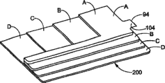
Fig. 3 is the top view of molding substrate before applying.Shown in substrate have a thickened areas and promote and/or guide coating composition to flow.
Fig. 4 and Fig. 5 are respectively the front and back views of substrate shown in Figure 3.
Fig. 6 is the side view of molding door-plate.Door-plate has the different zone of thickness and flows with the guiding coating composition.
Fig. 7 is the coated substrate in displaying surface of Fig. 4.
Fig. 8 substantially only is positioned at the substrate of the runner section of showing the surface for the coating of Fig. 4.
Fig. 9 is the front elevation view with the molding decorative panel on flat substantially displaying surface.
Figure 10 be have shown in the molding substrate in different-thickness zone.
Figure 11 is the base plane figure with removable flexibility restriction edge.
Figure 12 is along the sectional view of 12-12 line among Figure 11, is used for illustrating removable flange.
Figure 13 A to 13D is the sectional view of molding substrate with removable flange of different structure.
Figure 14 has the base plane figure that shows the removable flange that surface perimeter is extended around substrate.
Figure 15 A is base plane figure, and this substrate has at the removable flange of showing on surface and the periphery, and coating is limited in the presumptive area of showing the surface, Figure 15 B is the sectional view along 15B-15B line among Figure 15 A.
Figure 16 is the sectional view of the fixed mold of type shown in Figure 1.
Figure 17 A is the front view of molding substrate, this substrate has the zone that is easy to shrink in the position that coating composition is expelled to substrate surface, Figure 17 B is the sectional view along 17B-17B line among Figure 17 A, show the constriction zone below the coating composition injection point, Figure 17 C is the front view that applies the molding substrate of Figure 17 A.
Figure 18 A is the front view of molding substrate, the position that is expelled to substrate surface at coating composition has the zone that is easy to shrink, Figure 18 B is the sectional view of decorative panel shown in Figure 18 A, wherein the molding substrate is also in die cavity, coating composition has been applied on the displaying surface of substrate, and Figure 18 C is the front view of the coated article shown in Figure 18 B.
Figure 19 is the part schematic diagram of molding apparatus, and this device can apply the molding substrate and be combined with mold runner.
Figure 20 is the die cavity schematic diagram that has mold runner and introduce IMC composition inlet.
Figure 21 is the die cavity schematic diagram of Figure 20, and wherein die cavity is formed the composition filling by substrate, and has applied IMC.Mold runner with restriction lid prevents that coating composition from entering substrate and forming the material syringe.
Figure 22 is the mold runner schematic diagram in the half module, and Figure 22 (a) is the zoomed-in view of restriction lid shown in Figure 22.
Figure 23 and 24 is other mold runner schematic diagrames that have the restriction lid.
Figure 25 is the sectional view by the half module vertical component, and mold runner restriction lid is wherein arranged.
Figure 26 is the part front view of half module, is provided with obstacle near the gate stick device, enters the substrate injection device to prevent the IMC composition by gate stick.
Figure 27 is the part front view of coated substrate, has obstacle and enters the aperture that substrate forms the material syringe to prevent the IMC composition.
Figure 28 A to Figure 28 C is the partial cross section figure by mould, shows gate stick and is used for the obstacle that coating composition flows.
Figure 29 is the partial cross section figure by mould, shows the coated substrate that has obstacle, and this obstacle prevents that the IMC composition from entering the aperture that substrate forms the material syringe.
Figure 30 A to Figure 30 C has heteroid obstacle edge for the partial cross section figure by coated substrate.
Figure 31 A to Figure 31 D is a flow pattern, and it is lip-deep mobile at moulding article " displaying " to express the IMC composition.
The specific embodiment
In the accompanying drawings, identical identical or corresponding parts of numeral.
In Fig. 2, the half module 20 and 30 that illustrates is positioned at closing position, 42 adjacency or joint along the line of demarcation.As shown in the figure, show the sectional view of die cavity 40, although according to the product that finally will make, the die cavity of design size and shape can change a lot.Die cavity 40 has first surface 44 usually on first half module 20, the displaying surface of product will form on this surface, and corresponding rear side on second half module 30 or opposed second surface 46.Die cavity 40 is modified to and includes hole separately to allow substrate form composition and coating composition independently injection separately respectively.The position of syringe and injection orifice can change with the different of part according to the different of device, and can change according to the factors such as geometry of efficient, function, workpiece.
As shown in Figure 1, first (substrate formation) composition syringe 50 is typical injection mould devices, thermoplasticity and thermosets can be generally the resin of fusion, injects die cavity.First syringe 50 shown in the figure is " retreating " position, but it also can move in the horizontal direction, thereby makes nozzle or resin outlet 58 match and can inject to die cavity 40 with half module 20.
For purpose of explanation, first syringe 50 is represented as the reciprocating screw injection machine, and wherein first composition is placed in the hopper 52, rotary screw 56 move these compositions make its by heating extrude barrel 54, composition is heated to it here more than the fusing point.Heated material is assembled near the terminal of barrel 54, and screw rod 56 forces material to enter die cavity 40 by nozzle 58 as injection ram.Nozzle 58 all has check-valves at nozzle or screw rod top usually, enters screw rod 56 to prevent material reflow.
Owing to form the size and/or the complexity of part, extrudate can enter mould from the injection of a plurality of positions sometimes.In order to control flowing of extrudate in the arm, need heat extrudate.These tube passages can be called hot flow path or manifold system, are shown specifically in Figure 16.
In the operation, the substrate of scheduled volume forms material and enters the die cavity 40 from 50 injections of first syringe, has formed substrate or workpiece.The substrate that forms in the die cavity has surface of displaying 82 and opposed surface 84 at least.The thermoplastic substrate that is fit to includes but not limited to nylon, PETG (PET), acrylonitrile-butadiene-styrene (ABS) resin, polypropylene, polystyrene, acetal, Merlon, polyolefin such as polyethylene and polyethylene, polypropylene and polyvinyl chloride (PVC).This catalogue is not listed fully, just as signal.
This method relates to the mould design and makes, and it allows from second syringe 60 the IMC composition to be introduced the die cavity 40.The injection of IMC composition is to form material in substrate to begin after having reached the standard of enough accepting coating, perhaps begins when cavity pressure or temperature are in preset range.These conditions will be described in detail below.
In Fig. 2, second syringe 60 is connecting second nozzle, 62, the second nozzles 62 and is being arranged in the half module that does not contain first syringe 50.More specifically, the first composition syringe 50 that illustrates is arranged in fixed mold 20, and the second composition syringe 60 is arranged in removable half module 30.Yet the position of second nozzle 62 and quantity will depend on that workpiece wants coated part and its geometry.
As shown in Figure 2, IMC composition 90 injects die cavity 40 by second nozzle 62.Mould was not opened before applying IMC or unclamps.In other words, during the injection of two kinds of compositions, half module is all kept the line of demarcation and is remained on closed position.90 diffusions of IMC composition also apply predetermined portions or the zone of showing surface 82.
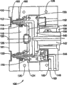
Figure 16 has depicted the conventional design of desirable first or fixed mold shown in Figure 1.Depicted among the figure and be used for the typical flow passage system of transport substrate material in the mould, and shown two kinds of cast gates, promptly be labeled as 160 heat top and be labeled as 170 valve gate system to die cavity.In Figure 16,100 is half module.Carry the polymer that processes from injecting unit by sleeve 112.Chamber plate 110 is the part of mould, and is adjacent with the part that will form.Nozzle head insulator 114 prevents chamber plate heat radiation.Nozzle heater 115 also is the part of this system, and the melted material that is used for keeping injecting is in suitable temperature.
The function of propping up pipe heater 118 is the temperature that keep arm 140.The function of cast gate insulator 120 is the parts as temperature maintenance system.Nozzle head 122 is actual point that the transporting molten material enters mould, is arranged in nozzle cage 124.The circuit that the water of heating or cooling or oil circulation are passed through according to the requirement of use polymer, is marked as 126 and 128.Propping up pipe heater 130, nozzle insulator 132 and air gap 134 all is the parts of temperature maintenance system.Locating ring 136 is used for mould is located with respect to injection nozzle.Cast gate heater 138 is positioned on the sprue bush 142.Valve gate 144 is parts of nozzle head 122 induction systems, starts by air open tube 150 and air enclosed pipeline 148.With the pressure in pressure sensor 180 Measurement dies; Usually use a plurality of such sensors.The temperature that serviceability temperature sensor 182 is determined in the mould; Usually use a plurality of such sensors.
The material injection that is used for forming substrate can be regarded one three step process as.The first step is commonly referred to the injection high pressure.Material is entered the pressure that is fit to that mould will use from mould machine injection can be determined according to experiment, but preferably wants make mold volumes be filled at least about 85-95% enough greatly.The time of pressurization, the size of plastics mould and structure all are decisive factors.Usually, increase pressure and flash occur, at this moment slightly reduce pressure until place, line of demarcation at mould.
Second step of injection is called the injection compression.It also can be determined by a series of experiment, preferably can be when finishing, and at least 99% of the loading mould cavity volume.
After the injection compression, reduce injection pressure to prevent workpiece deformation.Began for the 3rd step like this, be called injection and keep.The same with other stages, it also can be determined by experiment.
In the mould design, determine that system is extremely important about the final machine conditions of particular mold, particular substrate material and specific IMC material.In mould is provided with, must gets in touch a large amount of variablees, thereby within commercial acceptable time, produce the acceptable part.Other settings of pressure, time and injection machine change with the shape of wanting finished parts and/or employed polymeric material.
In order to optimize these and other the key parameter in the injection process, can carry out the flow simulating analysis and/or on existing mould (if present) or model, carry out a series of experiments according to the required product shape.In addition, can in the design of new mould, carry out flow simulating and/or experiment, thereby test and assess its performance and before mould puts into production, whether also need to determine to revise.According to these variablees, can calculate volume to fixed mold.Form the density of material based on above-mentioned calculating and substrate, charging what can be determined.Can attempt different machine variables, up to definite optimal results, but in the shortest time complete filling mould.In these experiments, one or more sensors and/or detector, gaging pressure and/or temperature when the different machine variable of conversion (as injection speed and pressure) are installed on mould preferably.Also can carry out to optimizing the flow simulating that operating parameter carries out based on this mould.
The allowable range of resin injection quantitative changeization is ± 0.5% charging gross weight.Such changing unit reason is because the compressibility of resin is made acceptable part within this scope.
Determine that the optimum operation variable in the new parts injection molded is a kind of iterative technique (being trial-and-error method).Although experienced technical staff has some ideas that need, still can produce a certain amount of waste material that has certain neotectonics.Select to determine some variable, for example barrel temperature, mold temperature, injection high voltage limit, injection keep-up pressure, injection speed, filling time and retention time.Also to carry out the operable state classification that terminal adjustment will mix up subsequently, be called as sort program this this.
Illustrate this program, carried out a series of experiment, used 771Mg (850 tons) the CINCINNATI MILACRON that revises
TMHydraulic clamp injection machine and mould are to determine the machine setting with respect to the best of multiple base material.The machine of being found that reaches optimum is arranged in the following Table I to be listed.These settings are to use sort program to obtain.The mould that uses in this program is similar to the valve cap of automobile engine, and basic configuration is to have the opening box that bends the side.
These results might not be applicable to other mould machine.Preferably carry out a series of new experiments according to the system that will revise.For different moulds or resin also is like this.In any case, all need to carry out same experiment to obtain the optimal operations parameter.
Following resin is used as substrate and forms material:
Embodiment 1:IMPET
TMEKX215 glass is filled polyester (Ticona; Summit, New Jersey)
Embodiment 2:IMPET
TMEKX230 glass is filled polyester (Ticona)
Embodiment 3:FORTRON
TM4184L6 polyphenylene sulfide (Ticona)
Embodiment 4:FORTRON
TM1140L7 polyphenylene sulfide (Ticona)
Embodiment 4:XENOY
TM2390PC/PBT alloy (GE Plastics; Pittsfield, Massachusetts)
Embodiment 5:NNP-30-2000 polystyrene (Nova Chemicals Corp.; Calgary, Alberta).
Table I: the molding of different thermoplastic plastics
| |
Embodiment 2 | Embodiment 3 | |
| Machine setting value nozzle (℃) barrel temperature, the A-D zone (℃) mold temperature, the 1-8 zone (℃) the fixed die temperature (℃) mobile mould temperature (℃) | 261 265,266,266,265 260,260,149,260, 149,260,260,260 117 135 | 261 265,266,266,265 260,260,149,260, 149,260,260,260 117 135 | 304 314,309,308,303 304,304,149,304, 149,304,304,316 133 147 |
| The injection high pressure, compression keeps (second) extruder delay (second) the core setting (second) that pauses forward of (second) cooling (second) Qi Mo (second) syringe | 10.0,4.0,4.0 90.0 0.0 0.99 0.0 0.8 | 10.0,4.0,4.0 60.0 0.0 0.0 0.0 0.8 | 10.0,3.0,2.0 60.0 0.0 0.0 0.0 0.8 |
| The injection high-pressure limit (MPa) injection |
15.2 6.9,6.9 6.2,6.2 | 15.2 7.6,7.6 6.2,6.2 | 15.2 5.5,5.5 4.8,4.8 |
Continued on next page
Table I brought forward
| Before injection rate (cm) delivering position (cm) decompress(ion), back (cm) | 7.87 3.56 0,0.76 | 7.75 1.78 0,0.76 | 6.86 3.05 0,0.76 |
| Injection speed, % injection rate Seq.1 Seq.2 Seq.3 Seq.4 Seq.5 | 1.25,80 1.10,60 1.00,40 1.00,20 0.60,X-FER | 1.25,80 1.10,60 1.00,40 0.60,20 0.60,X-FER | 1.25,80 1.10,60 1.00,40 1.00,20 0.60,X-FER |
Table I (continuous table)
| Embodiment 4 | Embodiment 5 | Embodiment 6 | |
| Machine setting value nozzle (℃) barrel temperature, the A-D zone (℃) mold temperature, the 1-8 zone (℃) the fixed die temperature (℃) mobile mould temperature (℃) | 304 314,309,308,303 304,304,149,304, 149,304,304,316 133 147 | 288 288,288,288,288 288,288,n/a,288, 288,n/a,288,288 109 141 | 272 282,282,276,272 -n/a- 86 119 |
| The injection high pressure, compression keeps (second) extruder delay (second) that pauses forward of (second) cooling (second) Qi Mo (second) syringe | 10.0,3.0,2.0 60.0 0.0 0.0 0.0 | 10.0,3.0,2.0 120.0 0.0 0.0 0.0 | 8.0,2.0,2.0 140.0 0.0 0.0 0.0 |
Continued on next page
Table I (continuous table) brought forward
| Core is provided with (second) | 0.8 | 0.8 | 0.8 |
| The injection high-pressure limit (MPa) injection |
15.2 5.5,5.5 4.8,4.8 | 15.2 8.3,8.3 7.2,7.2 | 15.2 9.7,9.7 8.3,8.3 |
| Before injection rate (cm) delivering position (cm) decompress(ion), back (cm) | 6.86 3.05 0.00,0.76 | 7.87 2.03 0.00,0.76 | 8.38 2.03 0.00,0.56 |
| Injection speed, % injection rate Seq.1 Seq.2 Seq.3 Seq.4 Seq.5 | 1.00,80 1.00,60 1.00,40 1.00,20 0.60,80 | 2.25,80 2.50,60 2.25,40 0.40,20 0.60,X-FER | 2.75,80 2.50,60 2.25,40 2.00,20 1.00,X-FER |
N/a=is inapplicable
Determined to make the operating parameter of substrate, also will be with reference to the form that is fit to or by measuring, determine substrate formation material melt temperature, thereby make the IMC composition to inject at reasonable time.By using sensor or the detector among above-mentioned Figure 16, can determine whether base reservoir temperature is cooled to below the melting temperature of its composition material.Perhaps, melt temperature can be leaned on observed pressure and directly determine.When moulding article reached its melt temperature, it began to shrink, thereby reduces pressure.
If do not use sensor, can determine to reach the time of melt temperature and the time that injection IMC composition begins, be used for control operation then.In other words, can determine that mould closure and substrate reach the time span between its fusing point, be used for controlling IMC composition start injection.
Improved machine and IMPET have been used
TM430 resins and STYLECOAT
TMX subbing (OMNOVA Solutions Inc.; Fairlawn Ohio) as the IMC composition, has carried out a series of experiment.By measuring temperature, determine that base resin fully is cooled to it below melting temperature at mould after closed 50 seconds.On three parts, used 90 seconds IMC hardening time.These parts demonstrate good coating effect and solidification effect.
Further use 33 parts to experimentize, to confirm the acceptability of these machine settings and all parts, i.e. good surface appearance and adhesiveness.Further the sample experiment is only just injected IMC after 30 seconds in the mould closure, and has only used 60 seconds hardening time.This part can't be accepted, because some part is only slightly applied.This has more determined the correctness that the front machine is provided with.
Another serial part uses VANDAR
TM9114PBT is as base resin.This resin is cooled to it below fusing point at mould after closed 30 seconds.These parts have all been expressed good surface appearance, promptly level and smooth coating and good adhesiveness.
For the necessity of (promptly after the surface of base resin just has been cooled to its melt temperature) injection IMC composition between being illustrated more clearly in when appropriate,, use the improvement TOSHIBA of hydraulic clamp with the too early or late inject contrast of mistake
TM950 injection machines, VANDAR
TM700 resins and as the STYLECOAT of IMC composition
TMSubbing has carried out a series of experiment (every group of 5 parts).Machine is provided with as above-mentionedly determines, and except inject time of IMC composition, i.e. interval number second between mould closure and the start injection IMC, and other machine is provided with identical.These result of experiment Table II is below listed.
Table II
| (second) at interval | Hardening time (second) | Applicator is provided with | Applicator speed | | Explanation | |
| 10 | 160 | 235 | Slowly | Difference | Coating is mixed with substrate | |
| 15 | 160 | 235 | Slowly | Difference | Coating is mixed with |
|
| 25 | 160 | 235 | Slowly | Difference | Coating is mixed with |
|
| 40 | 160 | 235 | Slowly | Good | Prolonging hardening time well solidifies the |
|
| 100 | 160 | 235 | Slowly | Difference | The coating adhesion is bad and covering is poor | |
| 120 | 160 | 235 | Slowly | Difference | The coating adhesion is bad and covering is poor |
These embodiment have shown the desirable property of determining and be provided with system, so that inject the IMC composition when the surface temperature of substrate has just dropped to below the melting temperature.Therefore, this method comprises the operating parameter of determining and the Best Times that comprises injection IMC composition being set.
As mentioned above, can in the presumptive area of substrate, selectivity apply.In addition, can also lean on designing mould to control the selectivity coating with the thickness or the degree of depth of control or modification substrate.Here, the thickness or the degree of depth are defined as from a surface of substrate to distance, girth or the size of opposed surface.That improves that thereby mould increases the IMC composition mobilely is usually directed to two thickness between the surface, and first surface of selected guiding of IMC composition or use is commonly called and shows or appearance surfaces, and the rear surface actual be reverse side.IMC can but be not that must to apply whole displayings surperficial.For example the thickness among Fig. 3 is meant from showing that surface 82 is to the back or the distance of reverse side 84.As shown in Figure 3, show that the thickness between surface and the substrate rear side is variable.
Every kind of intrinsic compressibility factor of substrate, promptly under the fixed temperature, given substrate meeting is with specific, computable percentage compression.Therefore, even mould-forming product or substrate have single compression ratio, bigger thickness or distance can be compressed in first area thicker than second area in the substrate.For example, the given compression ratio of substrate under certain temperature is 20%.Therefore, substrate thickness is that the part of 2.0cm can be shunk 0.4cm, can compress 0.2cm and other thickness is the part of 1.0cm following of same temperature.
Such compressibility can be leaned on improved in view of the above mould and the selection that is used for presumptive area in the substrate applies.The compressibility of substrate also can be applied to effectively guide IMC to flow to the definite zone or the path of substrate.
As mentioned above, IMC can put on substrate with multiple known method.With reference to figure 2, what illustrate is IMC (or second) composition syringe 60, and it is in the appropriate position of molding apparatus, as have nozzle 62 on half module 30.First composition of first quantity injects die cavity with required preassigned, forms substrate, workpiece or product, the decorative panel 100 shown in Fig. 3-5.
As shown in Figure 3, substrate has surface of displaying 82 and rear surface 84 at least.IMC composition 90 injects die cavitys from syringe 60 by at least one nozzle 62 subsequently, and 104 position on joint 103 as shown in Figure 4 is expelled to display surface one side of substrate.
In the injection of IMC composition with before solidifying and/or in the process, mould is not opened or is unclamped, and is exactly institute, enters in the process of die cavity in the injection of first and second compositions, and half module is keeping the line of demarcation, and the distance that remains substantially stationary usually each other.
Liquid IMC composition comes from injection point 104 distributions or radiation on displaying surface 82, and IMC composition syringe and the position of nozzle in improved molding apparatus are depended in the position of injection point.Therefore, the injection point of IMC composition basically can be in any position of showing on the surface 82, and is not limited to the position shown in the figure.
Thereby the IMC composition solidifies in substrate and forms coating.Can any thermal activation be cured, thermal source includes but not limited to molding substrate, mould itself, perhaps passes through the fluid heating of the controlled temperature of flow through molds.
The improvement of mould can comprise that importing or guiding IMC combined stream are to substrate.As mentioned above, by the variable of control moulding process, make the amount of the material of required substrate and can determine by experiment or flow simulating.First composition injected enter die cavity and be cooled to below the fusing point or reached enough acceptance or supported the temperature of IMC after, the IMC composition of scheduled volume is expelled on the injection point of substrate from syringe 60, is preferably in it and shows on surface.The pressure limit of coating composition injection is usually at about 3.5 to about 35MPa (500 to 5000psi), be typically from about 7 to about 30MPa (1000 to 4500psi), between die surface and substrate surface, spread thereby promote the IMC composition to leave nozzle.The mobile of control IMC is by improving the thickness or the degree of depth that mould changes base resin under the surface to be coated, making the favored area of IMC directed toward substrate.For example, if die cavity is designed to wanting that substrate has constant thickness under the regions coated, the IMC composition can spread from injection position with radiation, steady, constant mode substantially.Under the same correlated condition, if substrate forms the varied in thickness zone is arranged under surface to be coated, the IMC composition can be directed flowing to the bigger zone of relative thickness.Therefore, coating layer thickness also is transformable on the coating surface.The compressibility permission of substrate is more with respect to the basal region compression that second area has bigger thickness, and holds the IMC fluid better and promote it to move.Base reservoir temperature also is the factor of compression, and therefore also is the factor that influence is flowed.
In the possible mould design of another kind, be expelled to suprabasil position around the IMC composition, substrate is provided with thickness increases the zone.Increase thickness and mean that IMC composition injection position substrate thickness on every side is greater than other at least one zones of substrate or thickness of part.As shown in Figure 5, decorative panel 100 has joint area 103 at the IMC injection position.Thereby the thickness that can change joint area 103 is strengthened the guiding of IMC composition.Blank area 104 among Fig. 4 comprises thin part or limiting joint flange 102, goes out die cavity to prevent the IMC combined stream.Also can further discuss limit flange below.Thicker joint area has promoted that coating composition flows on the displaying surface 82 of substrate from the IMC nozzle relatively, because the IMC composition can be avoided the thickness of substrate minimum or less zone, for example joint as possible.
Also have a kind of selection, provide at least one " runner " part to substrate, the preferred flow passage, or promote the zone that the IMC composition flows in substrate.Runner is meant the zone thicker with respect to other adjacent area, and here the IMC composition can be by better guiding is mobile.Advantageously, runner section can be located in the substrate that designs complicated substrate or be not easy to apply.The runner section basal region around IMC composition injection point usually begins, from basad upward preposition or terminal diffusion here.For example, in the runner section 106 that Fig. 5 had is included in from joint area 103 extensions and with joint area 103, extend to the bottom 107 of decorative panel 100; Door-plate shown in Figure 6 has three runner section 109.According to the amount that injection enters the IMC composition of die cavity, the displaying surface with runner section can be applied fully or only be applied in the specific region, as only in the runner zone.The coated weight that adopts also can change with the position is different with coating thickness.
The degree of depth of runner section can be according to wanting coated substrate and design specification to change.Substrate can have the runner section that begins to extend from IMC composition injection areas, and it is thicker relatively, thereby makes the IMC composition of the substrate surface that is useful in fact all be maintained in the runner section.Therefore, can expect, use runner section, can produce many special effects by improving molding system.For example, can use runner section coating composition to be directed to the distal portions of substrate surface.The thickness of runner section can reduce in the direction away from injection point as required gradually, perhaps even can separate or be divided into a plurality of runner section, thereby reaches desirable coating effect.
Limit flange 98 is provided also can for molding substrate or product.As shown in Fig. 4, limit flange 98 can be extended fully around the substrate periphery, is specially decorative panel 100 as at least.Flange 98 can spray the line of demarcation as obstacle to prevent the IMC composition from spilling from die cavity.As shown in Fig. 3, flange 98 can be offset usually or be formed on and be lower than in the plane of showing surface 82 as at least.Therefore, show that surface 82 has the edge 83 that transition becomes flange 98.Show that marginal surface 83 declines form wall, with respect to showing that the surface becomes about 90 ° of angles.Substrate wall 86 stops at flange portion 98 places, and here flange portion extends outward with respect to 86 one-tenth about 90 ° of angles of wall.Show sharp-pointed relatively angle between surface 82 and the flange 98, and the relative Incoercibility of thin flange, all be considered to the important obstruction that the IMC composition flows.The thickness of flange 98 is usually less than substrate the thinnest part or zone.As shown in Figure 3, flange 98 is thinner than part 96, and part 96 is substrate the thinnest parts relatively.Flange 98 is basically around the whole periphery of the substrate surface that will apply, usually width is no more than about 0.57 to about 0.45cm (0.225 to 0.176 inch), it is desirable to be no more than about 0.44 to about 0.19cm (0.175 to about 0.076 inch), preferably be no more than about 0.19 to about 0.11cm (0.075 to about 0.045 inch).
As shown in Figure 7, IMC90 has applied the whole displaying surface of molding substrate.Because the structure of molding substrate and other moulding variables, coating 90 does not apply flange 98, although can apply.According to the design of flange 98, use usually less than IMC weight about 10%, it is desirable to less than 5% and preferably apply flange 98 less than 1% IMC.Flange 98 does not contain any other base material at its terminal edge.Between flange and line of demarcation, there are not other base materials or external flange.
Mould also can be improved to and include frangible, removable overlap or limit flange.The structure of the product of mould-forming, part or substrate is abideed by certain predetermined definite margin of tolerance mostly.The work that product usually is designed to can accurately to be assembled to or can accurately to be assembled to basically assembly or part is gone in arranging.Have extra limit flange and limit the common meeting of product of coating greater than concrete manufacturing tolerance.In addition, limit flange shows that the surface is not often applied by IMC, makes product appearance undesirable.
Liquid state, uncured IMC composition being limited within the target area of the substrate surface of being planned is unusual difficulty.On the die surface of these compositions around usually can flowing to or leak into, for example marginal around; On the non-displaying of the product surface that does not need to apply; Even can flow out mould itself.Another leaks relevant problem with coating, incorrect being compressed in the mould of coating composition meeting, cause some coated part outward appearance tarnish, some part does not have smooth film configuration or enough coating thickness, and perhaps some part does not show quality desirable or that require.Coating leaks into and can cause molding apparatus bonding and can't operate on the syringe pin.These over-current phenomenon avoidance can cause part to destroy and can not accept, and must the cleaning mold surface to remove the coating aggregation.
By with IMC limit flange or overlap flexible and that be easy to remove, for example goods are coated and coating solidifies that the back is manual to be removed, and introduce moulding article or workpiece, and the designed mould of the method according to this invention can prevent foregoing problem.Have removable limit flange product remove the back at it and just can be used for assembling.Possibility only partly be applied or an advantage of possibility and unhandsome removable limit flange is that it is easy to remove and abandon.Thereby, can produce and have ideal dimensions and the accurate part that applies fully of the quilt of standard.Saving work and cost also is other advantage that the coating limit flange is obtained, and waste minimizes.Removable limit flange can be eliminated painting operations, after-treatment and the cost of transportation between part mould machine and coating machine of part.
With reference to figure 11-15B, show mechanograph or substrate with removable flexible limit flange.Shown in Figure 11 is product 200.Its main surface or displaying surface 210 are coated.Because the existence of removable limit flange 220 can prevent that the IMC composition from flowing out and polluting the dorsal part of other die surfaces or moulding article from substrate surface.
Figure 11 also shows substrate and forms the substrate injection areas 230 that material injects mould.IMC composition injection areas 240 shows the entrance of IMC composition, and the IMC composition extends on the displaying surface subsequently.Except that the peripheral region of the injection areas 240 that has limited features, removable flange 220 extends to stop main surperficial overflow around the periphery of showing the surface.Shown removable flange 220 extends around whole displaying surface, if but can only extend on every side in the subregion, for example workpiece includes and can limit mobile geometry.Removable flange shown in Figure 14 is around extending around the substrate 200 main surfaces.Also show the injection inlet zone 240 of IMC composition.Equally, if having other limited features or in fact can not leak in the specific region, removable flange can not extend on the whole peripheral distance of substrate major part yet.
Removable flange is positioned at or is formed on the substrate surface, and this surface is in the displaying marginal surface of part or zone or plane between periphery and dorsal edge or the periphery.No matter use which kind of flange, each flange all has width and the degree of depth or height.As shown in figure 12, width A can be defined as the outward extending ultimate range of flange, perhaps the distance of base body C between the surperficial E of non-displaying that wants coated displaying surface D and its reverse side.Depth B can be considered to the degree of depth or gauge, and it can be along the wide variety of flange, and depth capacity appears at the outermost part of flange usually.Designed flange has very thin part in the position of close or contiguous substrate, is easy to fragmentation.Removing of flange is very easy, for instance, thereby its alternating bending is destroyed guide edge, and its edge with the main surface of part is separated.Though not necessarily, also can remove limit flange by tool using, as cutting edge, hot sword instrument, water spray, buffer, sanding machine, matching plane device etc.
Removable flange can have multiple structure.Figure 12 shows the cross-sectional configuration of Figure 11, and its flange 220 forms wedge shapes, the degree of depth of its outer end portion than join with base body and the removable part that links to each other bigger.Removable limit flange can only a side of 205 forms in the line of demarcation.The vertical side surface of base body and the angle between the limit flange upper surface can from about 10 ° to about 90 ° of variations, preferably from about 15 ° to about 30 °.Shown in Figure 13 A is the cross section of coated substrate 220, has in-mold coating 216 and triangular flanges 221 in the substrate 215.Structure shown in Figure 13 B is a rectangular flange 222.Also can be as use circle and the semicircular flanges shown in respectively among Figure 13 C and the 13D.Flange almost can be any geometry or design, as ellipse, and tear-drop shaped, or taper etc.
In order to make flange of the present invention be easy to remove, the attachment point of flange should enough approach, thereby can be easy on the substrate major part broken or separate.The thickness of flange depends on that substrate forms composition.Thus, at the attachment point place of contiguous substrate, the thickness of flange is less than about 0.7mm, 0.6mm or 0.5mm, and preferably from about 0.1mm to about 0.4mm.On the direction away from substrate major part attachment point, the thickness of flange can increase to the thickness of any needs, usually all can be greater than the thickness of attachment point.Flange width from the substrate major part to its surrounding edge is usually less than about 10mm, it is desirable to from about 2.5mm to about 8mm, preferably from about 3mm to about 6mm.
Can improve mould by machining, milling operation etc., make removable limit flange all form at aforesaid any half module or in two half modules.Usually flange forms along the one or both sides in mould line of demarcation 205, and example as shown in Figure 12.Because the design of the limit flange at the narrow attachment point of substrate major part place and basic Incoercibility, IMC mainly stops at the attachment point place between base body and the limit flange, as shown in Figure 13 A-D.In other words, formed the compression gradient, IMC can flow through thicker relatively, compressible substrate major part, but can not flow through relative edge than the limit flange of major part at the bottom of thin and the incompressible adherance basically.
Mould can be designed in such a way that removable limit flange expands on the surface of substrate, to prevent that the IMC combined stream is to showing on surface or other surperficial presumptive areas.The removable limit flange 320 that substrate 300 shown in Figure 15 A has has extended through a part of showing surperficial D, also extends around the part of substrate periphery simultaneously, and IMC316 is limited in the presumptive area of showing surperficial D.
Figure 15 B is the viewgraph of cross-section by 15B-15B among Figure 15 A.This view illustrates, and by removable flange 320, IMC316 is limited in showing in the predetermined portions of surperficial D.
Therefore, removable IMC limit flange can be used for any zone on any surface of substrate, with its predetermined portions of preferential coating.When removable limit flange is used in above the substrate, when going up, can in substrate, clearly limit coating border or zone especially for use in displaying is surperficial.In substrate, use limit flange can produce multiple different surface aesthetic effect, when particularly using removable limit flange.Obviously, the improvement of mould can comprise the limit flange of any amount.Limit flange can be used to produce pattern, design, sign, literal, symbol of any kind etc.The coating of different colours be can introduce in the zones of different of substrate, thereby covering, color contrast, special result etc. allowed with limit flange border.
Removable limit flange also can be used on the rim openings place of the substrate of contiguous removable mold office such as slide block or core.Removable flange will prevent or hinder the IMC composition and leak and to enter removable core zone and may be bonding with core.
With reference to figure 17A-18C, show another improvement of mould.Here, the IMC composition can be expelled to substrate surface core 310 places of substrate 325, shown in Figure 17 A, perhaps is expelled to substrate surface corner 410 places of substrate 400, shown in Figure 18 A.Usually, to be expelled to molding suprabasil when product uses and background for the IMC composition.Perhaps, the IMC composition can be expelled to suprabasil subsequently can be by the part that removes or excise from substrate.For example, if desired, the IMC composition injection areas in joint 103 positions among Fig. 4 can only stay the basic foursquare coated product that is from the excision of molding substrate major part junction.
As mentioned above, thus can promote the IMC composition to flow in zone or the compressible region that suprabasil IMC injection position is made thickness and increased relatively.Molding substrate 325 shown in Figure 17 A-C has compression difference to promote suprabasil flowing.The front view of substrate 325 during Figure 17 A, thus wherein can use limit flange 330 IMC to be limited in the displaying surface 302 of substrate.The IMC composition can be expelled in the mold cycle process on the injection inlet zone 310 of substrate.Substrate injection areas 312 also dots out, because substrate is to inject from the rear side 304 of showing surperficial reverse side, thereby streamline that can may occur after cast gate is removed or undesired edge stash.
The zone 308 that increases thickness has formed " flow region ", is used to select to control flowing of coating composition, and the thickness and the surf zone of gained coating thus.For example, because the zone that thickness increases relatively has the decrement of corresponding increase, with respect to the adjacent zone with thin relatively cross section, flow region has promoted IMC composition flowing on the substrate continuous surface.Because flow region is designed to select to control flowing of coating by the passage that increase (or dwindling) decrement is provided, flow region also can be adjacent with the injection position of coating, and different with other the complex section part with increase thickness as appearing in the scopes such as strengthening pillar or similar structures details.Yet these thickness increase the zone of (or dwindling) also can be used as flow region.Same, flow region can comprise the zone that reduces to compress, and for example occurs in thin cross section, as periphery flange.In this case, flow region does not need and the injection position adjacency as the restricted area of coating, and in fact perhaps can be away from injection position.
Shown in Figure 17 B is side cross-sectional view by the molding substrate of 17B-17B line among Figure 17 A.Show distance or thickness difference between surface 302 and the back 304.Cast gate 314 forms in the injection step of substrate.Provide zone 308 in the zone of 310 back, injection inlet zone, its thickness is bigger than basal region 306, thereby can promote the IMC composition to flow.308 zones have the thicker part or the bigger degree of depth at core, and the IMC composition here is injected into to be showed on the surface.The thickness of substrate reduces gradually from injection inlet zone 310, and is constant relatively to the base part 306 back degree of depth.The relative depth or the thickness in zone 308 provide the zone that is easy to compress for the IMC composition, thereby promote it to flow to other presumptive area of showing surface 302.Shown in Figure 17 C, IMC320 has applied fully and has showed surface 302.Perhaps, if desired, substrate 325 can comprise other compression difference zone, for example above-mentioned mold runner, and can utilize the compression of substrate to apply in the zone of selecting in advance.
Figure 18 A-C shows the constrictive Another application of substrate, produces compression difference in the injection inlet zone and flows to promote the IMC composition.Figure 18 A shows and has the substrate 400 of showing surface 402 and limit flange 430.The IMC composition is in entrance area 410 injections.Substrate forms material and is injected into the position of die cavity in regional 412 back.Figure 18 B is the part viewgraph of cross-section of the decorative panel 400 in the die cavity 440 between half module 442 and 444.This molding substrate is applied by IMC composition 420, and it enters die cavity by injection device 422 by the nozzle that access road 424 passes through regional 410 places.Also show mould line of demarcation 460.The IMC composition is injected into suprabasil regional 408, and other zones of the substrate that comprises zone 406 are compared in this zone, have bigger thickness.With respect to zone 406, because thickness increases, the substrate in the zone 408 is easier to be compressed by the IMC composition.Figure 18 C shows the front view on the displaying surface 401 of coated substrate 400.
Substrate in the position (shown among Figure 17 A 310) of IMC injection with other to want the thickness ratio of coated base part be from about 1.1: 1 to about 10: 1, it is desirable to from about 1.25: 1 to about 2: 1, preferably from about 1.3: 1 to about 1.5: 1.
Show the surface in order to promote the IMC composition steadily to flow through equably, other zones from IMC composition injection position to substrate have formed smooth transition or substantially invariable transition, as shown in Figure 17 B and 18B.Transitional region can be made as taper or slope.Certainly, also can be bonded on this other listed features, as runner section and coating limit flange, with flowing of control or promotion IMC composition.In addition, control substrate and/or mold temperature also can influence this flowing.
Figure 19-25 shows mold runner 22.With reference to Figure 20, the first shown composition syringe 50 contacts with half module 20, makes nozzle or resin outlet 58 match with half module 20, thereby can be injected into die cavity 40 by mold runner 22.Mold runner 22 is provided with passage in half module, be used for transmitting substrate composition from syringe 50 and enter die cavity 40.Mold runner also can be called gate bush, mold runner abrupt slope etc.
Figure 22 shows the schematic diagram of one type mold runner 22; this mold runner 22 can have can from half module 20 pressing plate 21 is separated or with the body element of its formation one; in other words; this mold runner can be independent, dismountable, different element, inserts and connects half module or can form or moulding in half module self.Mold runner 22 has first end and second end, and 23 and 25, and extend betwixt.First end 23 obtains melted material from the injection mould molding machine and second end enters die cavity 40 with material, material in die cavity, formed afterwards can be coated substrate.Remove in the zone of restriction lid, the cross section of mold runner 22 is cylindrical, to avoid producing stress, strain, and shearing force in the injection process in substrate; The shape that other are fit to includes but not limited to taper shape, spirality and taper etc.As shown in Figure 20, first end 23 that nozzle 58 is positioned at mold runner is used for molded operation as at least.Mold runner 22 comprises that restriction cover 27 to prevent that the IMC composition is mobile or to stop thisly flowing through passage 26 and entering mold apparatus 50.
Restriction lid being generally groove or space, and whole periphery or girth along at least a portion of mold runner passage between first end and second end extend.In other words, the restriction lid is generally a chamber, and a periphery section that centers on passage is formed in the mold runner, and is being basically perpendicular on the plane of channel axis usually.Each restriction lid has foundation and terminal or end portion, as at least among Figure 22 (a) 28 and 29 respectively shown in.Foundation 28 has predetermined width along the passage axial length.The restriction lid also has height and extends to external radiation from the passage periphery usually.
As above institute's record, the design of restriction lid or structure effectively prevent or stopped the IMC composition enter the mouth from channel outlet to the passage base material or pass through near it.After substrate formation composition was injected into die cavity, mold runner and restriction lid were also formed composition by substrate and are full of.The lid of filling utilizes the relative Incoercibility of substrate in this thin zone to prevent that as barrier the IMC composition from flowing.
In another embodiment of runner, the width of foundation or thickness are greater than or equal terminal part, as shown in Figure 23 and 24, to remove the substrate cast gate that is partly applied at an easy rate, to comprise the bossing that is formed in the restriction lid.The width of foundation can change, but usually scope is about 0.025 to about 6.5mm, and preferably at about 0.06mm to about 0.4mm.Therefore, the width of the terminal of restriction lid or outside radiant section is usually less than foundation.The height of restriction between foundation and terminal part lid can change, but scope it is desirable to about 0.2 to about 0.65mm about 0.1 to about 2mm usually, and preferably about 0.25 to about 0.4mm.The position of restriction lid can lay respectively at along between first, second end 23 and 25 of mold runner passage Anywhere.Preferably limit lid and be set to, can enter mold runner at this IMC composition towards second end.The restriction lid can be arranged on nearly position to the about 0.25mm of distance second end.The design and the position of guard shield depend on several factors, for example the diameter of runner, substrate composition and the needs that shift out molded parts from mould.
In Figure 22, restriction cover 27A and is shown in annulus between first and second ends 24 and 25, and its plane is perpendicular to the axis of passage formation.This annulus forms square turning in its end portion.Restriction shown in Figure 23 lid 27B is set at an angle, so that the cast gate that is formed by substrate of filling channel and restriction lid operates carrying out mould-forming and applying, and after coated part shifts out in the mould, can easily remove from mold runner.Lid 27B is provided with and passage formed become to take measurement of an angle Φ and the measuring height from the foundation to the terminal part usually.This angle Φ can it is desirable to from about 25 ° to about 65 ° from about 1 ° of extremely about 90 ° of variation, and preferably from about 40 ° to about 55 °.
Limit the channel diameter between the lid and second end 25 as shown in Figure 23, greater than the channel diameter between the restriction lid and first end 23.This structure makes that cast gate is easier to remove.Therefore, when cast gate was drawn out mould on the die cavity direction, restriction lid was for flexibility and consistent with the diameter space that provided in the passage near second end.The restriction lid also can be taper or wedge shape 27C as shown in Figure 24.
Figure 25 shows the cross section that passes through the half module vertical axis in the position of restricted lid 27 as occurring among Figure 22.Can see that restriction cover 27 peripheries around passage 26 and extended fully, mobile to stop the IMC composition by mold runner.In this embodiment, mold runner is columniform, therefore limits bezel ring, and extends around the ambient radiation of passage.
How to work in order to understand mold runner, 19-25 narrates the process that applies below with reference to the accompanying drawings, and substrate forms material and is introduced in the injection-moulding device, and here material is heated to above its melt temperature.Substrate forms material and moves through equipment and be deposited on the machine barrel end by rotary screw 56.In mold cycle, half module 20 and 30 is in closing position, and as shown in Figure 19, the substrate of fusion formation material injects from the nozzle 58 of injection-moulding device, enters die cavity 40 by mold runner 22.Usually, a certain amount of base material injection is entered die cavity so that final products are full of die cavity ideally.As shown in Figure 19, substrate forms material and formed the shape of die cavity, and comprises the gate portions of staying in the mold runner 53, and is consistent with its shape usually also fully with its filling.In case base material is injected into die cavity, begins to cool down and solidify, up to having reached the temperature that to use the IMC composition thereon.The injection of IMC composition enters on the displaying surface of base material in the die cavity 40.As shown in figure 20, syringe 60 injectable compositions are to the displaying surface 44 of base material.By exerting pressure, the IMC composition 62 is showing that surface 44 extends from entering the mouth.Because on the side identical with cast gate 53 and mold runner 22 that IMC is ejected at base material, IMC will flow to injection device 50 along cast gate 53.
Figure 21 shows the coated substrate in die cavity, has wherein used the restriction lid to prevent that the IMC composition from flowing by mold runner.Uncured IMC composition spreads apart on the surface of substrate, and also enters second end 25 of mold runner 22.Because the compressibility of watering gate material, this coating will upwards flow to cast gate from second end, 25 to first ends 23 of mold runner.Cover 27 in case the IMC composition runs into restriction, the restriction lid has just stoped any of coating further to be flowed, because the substrate composition in the restriction lid has relative Incoercibility.Therefore, stoped the IMC composition to first end 23 and enter injection-moulding device 50 and the substrate of polluting wherein forms material.
After the IMC composition is injected into die cavity, thereby it will solidify and be bonded at formation coating on the base material.Then, the half module that is fixed together is separated, and coated goods are removed together with cast gate 53, and it also has edge or projection that mold runner restriction lid forms.Because the projection that forms in the restriction lid is normally flexible, cast gate is easy to remove from runner.Because the IMC composition does not pollute injection-moulding device, there is not the IMC composition in flow passage system, to deposit, therefore can make other coated article.
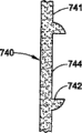
Figure 26-29 also shows another kind of mould and improves with control IMC mobile.Substrate 740 comprises obstacle 743, substrate injection inlet zone 744 and the IMC composition injection areas 746 at the obstacle edge that contains base material 742.Aforesaid limit flange 748 also is illustrated.Equally, the flange 748 that illustrates is fully round coated 741 coated basal regions, and according to the flow behavior of the structure and the mould of workpiece, this flange also can be that part is around wanting regions coated.In addition, because the existence of obstacle 743, substrate injection inlet zone 744 does not have IMC.
As shown in figure 27, obstacle edge 742 extends around substrate injection inlet zone 744.Obstacle edge 742 is included in the obstacle perimeter and rises or raised projections with respect to contiguous substrate surface.Typical substrate injection orifice is generally circular or cylindrical; Therefore, obstacle edge 742 has formed complementary shape on every side in this hole, can be that annular can be an Any shape usually still.
The height of obstacle edge and other parts of substrate can be measured from a side direction opposite side of substrate, for example from showing the surface to the back or reverse side, promptly between the Dui Ying half module, as mentioned above.Unless stated otherwise, the height at this edge or thickness are meant maximum height.The rising at obstacle edge or highly also can from show the surface measure to the end at edge.Symbol Y among Figure 28 B represents the height at obstacle edge, and having run through width substantially is the obstacle edge of Z.Design obstacle brim height Y width Z, thus prevent that IMC composition 741 from flowing at least in the substrate injection inlet zone 744 shown in Figure 28 C.The IMC composition is expelled to after the injection inlet zone 746 among substrate 740 lip-deep Figure 27, relies on the compression of substrate, and coating spreads apart on the surface between cavity surface and the substrate surface.At last, IMC composition 741 has arrived the bottom at obstacle edge 742, shown in Figure 28 C, and attempts to flow through obstacle edge 742 by compressed edge width Z.Width Z is thinner relatively, therefore stops that enough IMC composition 741 flows in the substrate injection inlet zone 744, shown in Figure 28 C, is because the width at edge is not easy to compression relatively at least, thereby forms IMC sealing or obstacle that coating flows.
Width Z can be made enough thin, make the IMC composition can not flow to the edge originally on one's body, more can not flow on the substrate injection inlet zone.Therefore, the ratio ranges of the thickness X of the substrate (shown in Figure 30 A) of obstacle border width Z and contiguous obstacle (from the substrate front to the back planar survey) is usually from about 0.1: 1 to about 2: 1, it is desirable to from about 0.25: 1 to about 1: 1, preferably from about 0.3: 1 to about 0.8: 1.Desired compression difference can change according to substrate composition, mold temperature and workpiece design etc., and can lean on limited test and determine easily.
The difference of the aspect ratio between obstacle brim height Y (742 among Figure 27) and the substrate thickness X prevents enough that also the IMC composition from destroying substrate injection areas or hole, its scope is usually at about 0.1: 1 to about 5: 1, it is desirable to from about 0.5: 1 to about 2: 1 preferably approximately 1: 1.
Figure 28 A-C shows the process that forms substrate injection orifice obstacle, and shows the part viewgraph of cross-section of the die assembly identical with the equipment of above-mentioned mistake shown in Figure 1 at least.Figure 28 A shows the partial view of the die cavity 40 between first and second half modules 710 and 712.In Figure 28 A, shown die cavity also has the projection that comprises edge 722 721 that forms obstacle.When gate stick 720 shown in Figure 28 B when inlet is return, substrate forms material 740, and 724 injections enter die cavity 40 in substrate injection inlet zone.As mentioned above, gate stick only is an embodiment of substrate inlet control.
In typical mold cycle, gate stick 720 724 is return from entering the mouth shown in Figure 28 B, makes substrate form material 740 and can flow to die cavity 40 to predetermined level.The obstacle 743 that comprises obstacle edge 742 also forms material by substrate and forms.After injecting the substrate formation material 740 of q.s, gate stick 720 moves to closing position shown in Figure 28 C and stops substrate to form flowing of material, and is in purpose attractive in appearance, reserves clean breakpoint on the layered product surface.
After the substrate cooling, reaching suitable standard or otherwise can accept liquid in its surface, coating composition just is injected into die cavity.In injection process, IMC composition 741 flows through the surface of substrate, up to running into obstacle 743.In case arrive obstacle edge 742, IMC composition 741 is pressed to die cavity with the edge and stopped to flow to the substrate entrance area or the substrate injection orifice, be at least because the width at substrate obstacle edge is incompressible highly relatively along it.Therefore, shown in Figure 28 C, IMC composition 741 is prevented from arriving or flowing to gate stick 720 and passes through from its centre or its peripheral gap.
Figure 29 shows the used obstacle of substrate injection device of not being with gate stick.Correspondingly, as mentioned above mould is improved, obstacle is provided for the substrate injection orifice, although can not use gate stick.Because the existence of obstacle, the IMC composition can not enter substrate injection inlet zone.
With reference to figure 9, show the mould that is used to make decorative panel 200, be designed to accept the IMC composition.The die cavity width is 30.5cm, and length is 52cm.Mould has the mould gate of hydraulic pressure in the centre of substrate injecting cavity, thereby and has taper joint IMC is introduced piece surface.Joint is positioned at the die edge part.The thickness of joint and part A is 0.003mm, and part B thickness is 0.0025mm, and portion C thickness is 0.002mm, and part D thickness is 0.0015mm.Have four laminates and on the vertical plane of part right side, have four laminates at this decorative panel on the horizontal plane of the left side of part.It is long and 13cm is wide that plate on the horizontal plane of part right side is of a size of 15cm.Board size on the vertical plane is that 3.8cm is wide and 52cm long.This decorative panel does not have the IMC limit flange.Mould is placed on the CINCINNATI MILACRON of 771Mg (850 tons)
TMVISTAL
TMIn the injection machine.The ABS resin injection that is heated to 249 ℃ enters die cavity, thereby produces the decorative panel of the part A-D with above-mentioned size and thickness as shown in Figure 9.The decorative panel front is a smooth surface, and the decorative panel rear side has shown the profile variations of different-thickness.After postponing or keeping nearly 120 seconds of clamping time, STYLECOAT
TMCoating composition is expelled on the front surface of decorative panel by the blank area of decorative panel.It is how to flow on the different piece of decorative panel that following table has been expressed coating composition in detail.
| Amount (the cm of IMC 3) | %IMC sprays fully | Part A % filling/mm | Part B % filling/mm | Portion C % filling/mm | Part D % filling/mm |
| 0.52 1.05 | 25 50 | 75/0.025 98/0.076 | 15/0.013 85/0.041 | 0/0 10/0.015 | 0/0 0/0 |
From wanting coated piece surface zone, and the coating layer thickness that requires, determine 1.97cm
3The amount injection fully that can form IMC apply whole decorative panel.
As seeing that be expelled on the decorative panel surface based on IMC, when having used 25% complete emitted dose, upper left plate and inboard vertical panel (runner section A) are preferentially applied in the table.Therefore, this embodiment demonstrates A and partly is effective runner section, and coating is easier to along A partly flow down decorative panel thus, and is flowing to part B, flows to its side before C and the D.When having used 50% the complete emitted dose of IMC, IMC begins to flow in portion C from part A and B.
Decorative panel shown in Fig. 9 is flange without limits.When coating has used when surpassing 50% complete emitted dose, coating composition leaks out die cavity by the line of demarcation.Therefore confirm, need IMC composition limit flange to keep the IMC composition on the required part of substrate surface.
Figure 10 shows the thermoplastic product 300 that has different base thickness.The example part uses 45Mg (50 tons) injection machine and 15cm square steel mould to make, and the two has all done improvement as above.It is that PET thermoplastic and IMC are STYLECOAT that substrate forms material
TMSubbing.Mold temperature is 121 ℃, before the injection of IMC composition is arranged 30 second time delay.
Part E (0.29cm is thick), part F (0.22cm is thick) and the different part thickness of part G (0.15cm is thick) representative, as shown in the table.Section H (0.15cm is thick) is represented the design of joint, has used thicker mid portion so that nozzle tip position movement-oriented.The thin cross section restriction flange of part I (0.06cm is thick) representative.The effect that has the mould design of thin and thickness portion is to help guiding IMC to flow in an ideal way.This can show in several ways, comprise:
1. guide flowing of IMC composition in joint location (section H), on the surface with IMC composition preferential deposition part in the mould line of demarcation.
2. guiding IMC combined stream is to more critical zones (part E, F, and H).
3. along the flowing of mold periphery and/or other mould parts restriction IMC composition, it is limited on the predetermined surface of part and within line of demarcation (part I).
The IMC coating rate of observed mould is as follows:
| %IMC sprays fully | Part E % filling/mm | Part F % filling/mm | Part G % filling/mm | Section H % filling/mm | Part I % filling/ |
| 50 80 100 | 100/0.076 100/0.10 100/0.10 | 80/0.051 100/0.076 100/0.076 | 20/0.025 40/0.051 100/0.076 | 100/0.051 100/0.76 100/0.10 | 0/0 0/0 0/0 |
The advantage of the mechanism that the reinforcement shown in the front is flowed comprises: because the thickness difference, and flow priority or deposit in the selection zone of part and use the flange in thin cross section that the IMC composition is limited on the piece surface.
This method relates to the mould design of using about injection machine and makes, and makes mould can be used for making coated article.Injection machine can be any known injection machine, has an injection device at least and comes injected molten material.This injection machine can comprise independent equipment and inject the IMC composition or also can comprise a total system.
If produced certain products earlier, its existing mould of testing and assessing, thereby obtain the information of mold flow and understand the optimal flow parameter of existing mould, comprise the type of operating temperature, pressure, use resin, based on the mold temperature and the mould filling pattern of use resin.Can carry out flow analysis according to the structure naturally of workpiece, to determine that substrate formation material and/or IMC composition are in possible the flowing of mould inside.Whether flow analysis can be used for determining nozzle location and must maybe need to flow strengthening or restriction.
Determining that the best of workpiece or preferred resin can relate to reexamines the selected specific resin of workpiece designer and/or original used resin of workpiece (if making earlier).Some resin can not be used for sufficiently high temperature so that IMC composition on it solidify (usually from about 38 ° to about 149 ℃ of curing).Therefore must selection can and can satisfy the requirement of product designer with the shared resin of required IMC composition; Otherwise just must carry out mold heated solidifies the IMC composition.
Can be identified for the type of the tool steel of mfg. moulding die; Different tool steel has different characteristics, thereby can influence their machinability and serviceability.In addition, the mould design can comprise the optimization of cavity surface.The situation of cavity surface has been reflected on the surface of workpiece.The surface of the work that coarse die surface is made is matt or coarse.Though this may be desirable for the better cohesive that subsequently mould applies operation outward, the lustrous surface of IMC or quality can be affected.Equally, the taking-up of workpiece after lustrous surface can influence molding and finishes; From press polished die cavity, take out workpiece than easier from unpolished die cavity.In addition, if die cavity will just be needed to adjust the performance of die cavity in the mould design by chromium plating.(die cavity of chromium plating can provide splendid appearance, the taking-up performance and the die life of mould; Yet chrome-plated surface is thinner relatively, therefore is difficult to revise or maintenance chromium plating die cavity.)
Mould can be designed as the guiding resin from displaying surface that the resin injection nozzle flow to mold runner the die cavity and workpiece separately.Because the mold temperature around the mobile substrate syringe and the syringe heater of passing of substrate, runner is higher than other mould parts, and as mentioned above, the mobile comperssibility influence that is subjected to base resin of IMC composition, it also is subjected to the influence of resin temperature conversely; Therefore, increasing of mold temperature can influence flowing of IMC composition near the flow passage system.This can cause the problem and/or the coating problem of solid colour.Yet, if design based on workpiece, mold runner must be positioned at the displaying near surface, mould can be designed as to comprise and is positioned near the additional mold cools down of runner or is positioned near the mold heated of adding of other parts of showing the surface, shows the mold temperature of near surface and promotes the IMC composition steadily as one man to flow with balance.
Mold cools down and/or heating can be used to help resin solidification and/or control resin flows.Mold cools down can be used for shortening the necessary time of workpiece resin solidification and can be used to the mold temperature that keeps desirable, and mold heated can be used for preventing that resin from just solidifying before whole die cavity is full of.This is very important for big and/or baroque workpiece.The equipment water that typical injection molding device has cooling carries out mold cools down.Usually the first kind as mold cools down is by the cooling tower cooling and makes the water of temperature between 10 and 32 ℃.Second type uses devaporizer to make the water of temperature between 21 and 32 ℃, if but also can higher environment temperatures be higher than 32 ℃.The water of the 3rd type is to add hot water, and wherein the injection mould device comprises the ability that adds hot water and will add hot water supply molded operation.Molding apparatus can also have the oil heater that adds deep fat, is used for further controlling mold temperature.Mould can use the water and/or the oil of the controlled temperature of one or more such types to control flowing of IMC composition.Utilizable mould design is included in and increases cooling or heating pipe line in the half module, allows the predetermined of fluid that heat and/or cooling to flow.In addition, need heating and/or the cooling fluid of design molding system to accept one or more types.
As mentioned above, the mobile compression that is based on substrate of IMC composition, it also is a function of base reservoir temperature conversely.When substrate was cooled off, it began to solidify, and the compressibility of cured substrate and molten resin are different.Can use the temperature of cooling water reduction superheat region, for example the mould part around the runner.These zones that focus in the mould can cause substrate are more than other colder zone compressions.Finally, seek the IMC composition of resistance minimal path, can flow to the bigger focus of compression.Focus can be located by increasing cooling capacity or use cold water.Also be like this for showing that coated zone is wanted at last in the surface on the contrary.These regional resins can be with regard to sub-cooled before coating composition has an opportunity to apply this surface fully.Because these basal regions have the compression ratio that reduces, the IMC composition can just stop to flow before arriving the surperficial end of displaying.Mold heated can be slowed down the curing of substrate.Designing mould makes and adds hot water and/or oily by these zones, thereby substrate keeps molten condition to strengthen flowing of IMC composition.
Mould can be designed as the controlled temperature water and/or the oil that use one or more such types and helps IMC curing.As mentioned above, IMC solidifies based on heating, more specifically, and based on the heating of substrate and solidify.Therefore, designing mould based on employed resin and IMC, by optimizing mold temperature, can promote the curing of IMC for comprising heating and/or cooling line in the surperficial mould part in contiguous the displaying.
Can formerly be used for making on the existing mould of the mechanograph discussed and/or workpiece pattern and carry out flow simulating or analysis, the possibility that flows according to the flow behavior of material and reinforcement and/or restriction be determined the optimal design of mould.Design relates to and obtains required IMC composition flow pattern, comprises the displaying surface that acquisition applies fully, minimizes mobile route (particularly metal coating), and minimizes unwanted IMC and flow.Flow analysis has been determined the optimum position or the place of IMC nozzle by showing surface gridization, and determines that based on the mechanograph characteristic of molding or the design technology (as flow simulating software) that can use a computer the IMC composition flows.Flow analysis can also determine whether that necessity maybe needs to use a plurality of IMC composition nozzles.Also can or carry out flow analysis before the mould design is finished afterwards.
Relate to the product design of showing the surface and affect the improvement that mould is done.These improvement relate to the required IMC composition flow pattern of acquisition, comprise the displaying surface that acquisition applies fully, minimize flow circuits (particularly metal coating), and minimize unwanted flowing.
If show that the surface comprises rib, projection (inside opening) or complex surfaces, the IMC composition can flow not according to necessary requirement.The mold runner that design can comprise additional guiding and/or promote to flow.By generating the zone that increases part thickness, utilize the substrate compressibility that increases to strengthen flowing.In a word, can change the design of product, thereby the compression promotion or the guiding IMC composition that increase substrate flow.
Perhaps, if show that the surface is near line of demarcation, core, slide block, shut off valve, inner line of demarcation or discharge bar, mould design needs to introduce design be used for limiting the element that the IMC composition flows, and wherein the IMC composition is to be introduced into die cavity and to advance according to the path of resistance minimum under very large pressure effect.Therefore, if show that the surface comprises any these die assemblies, can leave the displaying surface by these assemblies IMC composition, these assemblies stop IMC to apply fully and show that the surface also can influence the function of mould.Therefore, test and assess the mould design to determine whether the IMC composition can flow to these die assemblies or position.The IMC that the pressure effect is applied down can enter any opening greater than about .025mm.For example, discharge or core bar have the gap of .05 or .075mm usually, and therefore, include discharge or core bar if show the surface, and the IMC composition will enter discharge or core bar chamber and discharge or core bar are quit work.For line of demarcation, core, slide block, shut off valve and inner line of demarcation also is the same.If determined showing on the surface or needing the assembly of such type near it, the design of the product of will testing and assessing can prevent that to determine its element design that whether comprises the IMC composition from flowing to or flow out these zones.For example, if given layered product originally has the flange consistent with the line of demarcation in showing around the surface, improve with regard to not needing.The flange that itself has can be used for limiting and flow.Yet, as the feature of self structure not having of fruit product, can adjust mould design and introduce the flow restriction feature, preventing that the IMC composition is unwanted flows.
Based on test and/or flow analysis or mould simulation, can determine the optimum position of IMC syringe nozzle, mould is designed to each nozzle and comprises opening or aperture.In case determined desired location, the flow simulating analysis that just can add is determined or is revised this position.
Nozzle is preferably at mould self periphery, and at an edge showing the surface.Consider the position with respect to mould, IMC composition nozzle is removable die assembly, and therefore nozzle passage helps mould to safeguard.Turn to respect to the position of showing the surface, the visual fault relevant with moulding process can be minimized at the IMC nozzle of showing marginal surface.Flow analysis also can be used for need determining whether the optimum position of a plurality of IMC composition syringes and definite a plurality of syringes.More specifically, the IMC composition preferably is inducted into die cavity like this, makes that all surface of showing the surface is steadily applied, and outward appearance does not have mobile trace.Flow analysis determines that the optimum position of IMC composition syringe is to obtain required flowing.Preferably layeredly flow through and show the surface.In addition, can be according to aforesaid mobile intensive or the limiter nozzle location of testing and assessing, to determine best arrangement of nozzles.
With reference to figure 31A-D, show four kinds of different arrangement of nozzles forms.That Figure 31 A has described is less, complicated parts 530 not too, and wherein single nozzle 62 just enough applies whole displaying surperficial 532.In this embodiment, nozzle is positioned at the center of showing the surface, has produced laminar flow 534 on all directions around the nozzle 62.Figure 31 B-D has described to have and has showed the bigger of surface 538 and/or than complicated parts 536, single nozzle has been not enough to produce apply fully shows the necessary mobile level in surface.Among Figure 31 B, show at two nozzle 62a that show surperficial 538 both sides and 62b.The result has produced two strands of independently IMC streams 540 and 542, and it flows toward each other and is showing meeting in conjunction with striped 544 places of surface central authorities.In addition, when two strands independently IMC stream meets each other, formed bag 546 and 548.The result can see in conjunction with striped and bag 546 and 548 not coated in the workpiece of finishing.Figure 31 C shows and is better than two arrangement of nozzles shown in Figure 31 B.At this, nozzle 62c and 62d are spaced from each other in the same side of showing the surface.As a result, two nozzles have produced unified single laminar flow.In this layout, be flowing in a side of showing the surface and begin and flow to an opposite side together, thereby can not produce in conjunction with striped, airbag also is minimized.In addition, the contiguous marginal surface of showing of the airbag of any generation, this is an acceptable.With reference to figure 31D, more flow if desired, mould be can improve and three arrangement of nozzles 62e, 62f and 62g comprised; Yet, thereby three preferably still such layouts of nozzles can produce single laminar flow.If desired, can change independent nozzle 62e-g, flow to provide required.At this, nozzle 62f can receive 75% flow and nozzle 62e and 62g receive only 25% flow altogether.Though find to use three nozzles to be enough to obtain required flowing, also can use more nozzle.In addition, the said mobile intensive that comprises mold heated and/or cooling also can be used for a plurality of arrangement of nozzles and obtains required flowing above.
The size of actual nozzle and structure (comprising internal diameter) depend on the volume that applies the surperficial necessary IMC composition of displaying.The preferred nozzle of installing can be dismantled cleaning and/or change, and the nozzle top is configured to corresponding with the die cavity wall shape.
The mould design also can comprise the test and appraisal and the improvement of resin injector, can not enter resin injector to confirm the IMC composition.Resin ejection nozzle at first needs to consider about the position of showing the surface.If resin ejection nozzle is not being showed within the surface or near inadequately, just there is no need to introduce similar movement restriction device.If nozzle is within the scope that the IMC composition flows, the design of the nozzle of preferably testing and assessing can not enter to guarantee the IMC composition.Can enter resin ejection nozzle if determine IMC, the mould design can be introduced a kind of in the multiple limit flange of having discussed, prevents that the IMC composition from entering resin injector.In addition, the mould design can comprise that the cooling strengthening system reduces the rising of the mold temperature that may occur around the nozzle.
The present invention includes the flow analysis that carries out a series of test and/or new die and particular polymers material, come the optimal production process.In the mould design, determine that according to specific mould, specific base material and specific I MC composition the final machine conditions of system is very important.In mould is provided with, in commercial acceptable time scope, produce acceptable part thereby must get in touch a large amount of variablees.Other of pressure, time and injection machine are provided with and can change with the polymeric material of the shape of wanting converted products and/or use.In order to optimize these and other the key operation parameter in the injection process, can calculate capacity, and, can determine charge according to calculating and the density of substrate formation material to fixed mold.Can attempt the different machines variable up to determining best, complete filling mould in the shortest time.Preferably in these experiments, assemble one or more sensors and/or detector to mould, when changing different machine variables (as injection speed and pressure), gaging pressure and/or temperature.
Claims (11)
1. the method for a mfg. moulding die is used in the molding system that can make the coated mechanograph at least one surface, and described system comprises:
(i) mould machine, described mould machine comprises mould, described mould has first and second parts, die cavity can be operated and form to described first and second parts between the open and close state, in described die cavity, form described mechanograph, described mechanograph has the surface that at least one will be coated, and
(ii) distributor, be used for sending into coating composition in the described mould and delivering to described at least one surface, described first and second parts are fixed relative to one another at described closure state simultaneously, described distributor is communicated with described mould machine fluid so that described coating composition can be introduced described die cavity by one or more injection nozzles, described injection nozzle is bonded on one or two interior one or more holes that enter of described mould part
Described method comprises:
A) the described goods of test and appraisal and described at least one surface;
B) flowing of the described coating composition of simulation by described at least one surface, described mechanograph is formed in the described die cavity simultaneously;
C) determine one or more preferred introducing points at least one nozzle in described mould, by described nozzle, described coating composition is injected into described die cavity;
D) respond described simulation, make described mould part and make one or two of described mould part comprise:
(1) be positioned at described one or more holes that enter of described one or more preferred introducing points, and
(2) during described coating composition is delivered to described mould, utilize the substrate compressibility to control the flow governor that flows of the described coating by described at least one surface,
Can merge to described mould machine and be used in described mould part in the described molding system.
2. the method for claim 1, wherein said approximate simulation step comprises: carry out the flow simulating analysis of at least one described goods, determine best mould design and described coating composition, thereby determine the optimal flow path of described coating composition on described goods.
3. claim 1 or 2 method also comprise step: determine that preferred described goods form at least a in material and the preferred coating compositions material.
4. the method for claim 1 also comprises step: determine at least a in the best mold temperature of the described coating composition of injection and the best base reservoir temperature, thereby produce required flowing.
5. the method for claim 1 also comprises step: described mould is carried out the flow simulating analysis, flow to optimize described coating.
6. the process of claim 1 wherein that described flow governor comprises that one changes the constrictive die cavity shape of described substrate, to revise described coating composition flowing on the respective surfaces of described mechanograph.
7. the process of claim 1 wherein that described flow governor comprises mold runner, adjusts at least a with in the device of the temperature that changes described die cavity at least a portion and the flange of described mold temperature.
8. the process of claim 1 wherein that described mould comprises that at least one is used for measuring at least one sensor of machine and mould variable.
9. the process of claim 1 wherein that described at least one nozzle is a plurality of nozzles, described method also optionally comprises the positioning step of described a plurality of nozzles, so that described coating composition is stratiform described at least one lip-deep flowing.
10. the method for claim 1 also comprises: mould die cavity comprise one than the thickness portion substrate with the compressibility that increases described substrate and increase described coating and flow the lip-deep described of described part.
11. the method for claim 1 also comprises: mould die cavity and comprise that thin part substrate is with the compressibility that reduces described substrate and reduce described coating and flow the lip-deep described of described part.
Applications Claiming Priority (2)
| Application Number | Priority Date | Filing Date | Title |
|---|---|---|---|
| US43278802P | 2002-12-12 | 2002-12-12 | |
| US60/432,788 | 2002-12-12 |
Publications (2)
| Publication Number | Publication Date |
|---|---|
| CN1723108A CN1723108A (en) | 2006-01-18 |
| CN100441392C true CN100441392C (en) | 2008-12-10 |
Family
ID=32507993
Family Applications (1)
| Application Number | Title | Priority Date | Filing Date |
|---|---|---|---|
| CNB2003801055868A Expired - Fee Related CN100441392C (en) | 2002-12-12 | 2003-12-12 | Method of designing and producing a mold |
Country Status (9)
| Country | Link |
|---|---|
| US (1) | US7289874B2 (en) |
| EP (1) | EP1578580B1 (en) |
| JP (1) | JP4625330B2 (en) |
| CN (1) | CN100441392C (en) |
| AT (1) | ATE410287T1 (en) |
| AU (1) | AU2003297940A1 (en) |
| CA (1) | CA2508012C (en) |
| DE (1) | DE60324026D1 (en) |
| WO (1) | WO2004052616A1 (en) |
Families Citing this family (13)
| Publication number | Priority date | Publication date | Assignee | Title |
|---|---|---|---|---|
| US20040148051A1 (en) * | 2003-01-28 | 2004-07-29 | Omnova Solutions, Inc. | Modeling method and program for in-mold coating an injection molded thermoplastic article |
| DE102004062510A1 (en) * | 2004-12-24 | 2006-07-06 | Bayer Materialscience Ag | Forming and coating process for production of automobile interior components involves forming substrate in one tool cavity, transferring to second cavity in same tool and applying varnish |
| US7846369B2 (en) * | 2006-03-29 | 2010-12-07 | Akopyan Razmik L | Apparatus and method for molding polymer parts by displacement injection molding |
| FR2943939B1 (en) * | 2009-04-03 | 2011-06-10 | Plastic Omnium Cie | PROCESS FOR MANUFACTURING A THERMOPLASTIC MATERIAL PART AND COMPRISING A COATING. |
| US8589134B2 (en) | 2011-02-11 | 2013-11-19 | Gentex Optics, Inc. | Method and system employing flow simulation for improving material delivery in lens manufacturing |
| US20120235436A1 (en) * | 2011-03-17 | 2012-09-20 | Ford Global Technologies, Llc | One-piece decorative trim bezel having plural unpainted finishes |
| CH706504A1 (en) * | 2012-05-14 | 2013-11-15 | Schoettli Ag | A process for producing a syringe barrel for medical use and an apparatus for carrying out the method. |
| JP6219227B2 (en) | 2014-05-12 | 2017-10-25 | 東京エレクトロン株式会社 | Heater feeding mechanism and stage temperature control method |
| RU174291U1 (en) * | 2017-06-13 | 2017-10-10 | Общество с ограниченной ответственностью "Комбинат композитных материалов" | DEVICE FOR INJECTION FORMING OF NODE ELEMENTS OF REINFORCED MESH FROM POLYMERIC MATERIALS |
| US11685093B2 (en) * | 2017-09-08 | 2023-06-27 | Nissei Asb Machine Co., Ltd. | Mold |
| CN109940826A (en) * | 2017-12-20 | 2019-06-28 | 深圳市美好创亿医疗科技有限公司 | Warpage preventing Double-color forming die and forming method |
| CN110823057B (en) * | 2019-12-25 | 2021-07-30 | 铭昊汽车金属零部件(广州)有限公司 | Detection tool and detection method for detecting length of workpiece |
| CN113442379B (en) * | 2021-05-25 | 2022-07-12 | 宁波东发塑料制品有限公司 | Injection mold of motormeter installation casing |
Citations (4)
| Publication number | Priority date | Publication date | Assignee | Title |
|---|---|---|---|---|
| US4668460A (en) * | 1985-04-02 | 1987-05-26 | The Sherwin-Williams Company | Method of molding and coating a substrate in a mold. |
| JPH0732416A (en) * | 1993-07-22 | 1995-02-03 | Asahi Chem Ind Co Ltd | Coating method for thermoplastic resin molded piece with thermosetting resin |
| JPH0948044A (en) * | 1995-08-07 | 1997-02-18 | Dainippon Toryo Co Ltd | Mold for in-mold-coating molding and method for in-mold-coating |
| JPH0952262A (en) * | 1995-08-11 | 1997-02-25 | Mitsubishi Eng Plast Kk | Mold for in-mold coating molding method |
Family Cites Families (37)
| Publication number | Priority date | Publication date | Assignee | Title |
|---|---|---|---|---|
| US4118051A (en) * | 1976-12-17 | 1978-10-03 | Nissei Plastics Industrial Co., Ltd. | Injection molded ski and method for producing the same |
| US4389358A (en) * | 1981-06-22 | 1983-06-21 | Kmmco Structural Foam, Inc. | Method and apparatus for making an integral structural cellular and non-cellular plastic or resinous article with a smooth outer surface |
| US4414173A (en) * | 1981-11-02 | 1983-11-08 | The General Tire & Rubber Company | In-mold coating |
| US4534888A (en) * | 1982-10-25 | 1985-08-13 | The General Tire & Rubber Company | In-mold coating |
| US4539259A (en) * | 1984-07-02 | 1985-09-03 | Crown Zellerbach Corporation | Laminate for making tubes |
| JPS62160216A (en) * | 1986-01-08 | 1987-07-16 | Mazda Motor Corp | Method and device for in-mold coat |
| US4840553A (en) * | 1986-03-20 | 1989-06-20 | Canon Kabushiki Kaisha | Metal mold structure for molding multi-layer resin |
| US4931234A (en) * | 1986-05-12 | 1990-06-05 | Husky Injection Molding Systems Ltd. | Coinjection of hollow articles and preforms |
| US4711602A (en) * | 1986-07-17 | 1987-12-08 | Precision Rubber Products Corporation | Turbulent flow gate for the injection molding of tubular parts, including parisons suitable for blow molding |
| JPH0452114A (en) * | 1990-06-20 | 1992-02-20 | Mazda Motor Corp | Resin molding device |
| JPH04184502A (en) | 1990-11-19 | 1992-07-01 | Sekisui Chem Co Ltd | Centralized managing method for molding facility |
| JPH04288212A (en) * | 1991-01-07 | 1992-10-13 | Mazda Motor Corp | Jushiseikeihoho |
| DE69328168T2 (en) | 1992-06-30 | 2001-01-25 | Matsushita Electric Works Ltd | METHOD AND DEVICE FOR PRODUCING A PLASTIC ITEM CONSTRUCTED FROM A MOLDED BODY AND A MOLDED COATING |
| DE69408195T2 (en) * | 1993-04-26 | 1998-11-05 | Gencorp Inc | Conductive molded coatings |
| GB9323339D0 (en) | 1993-11-11 | 1994-01-05 | Rover Group | A method of moulding and a moulding formed by such a method |
| US5902534A (en) * | 1994-09-21 | 1999-05-11 | Mitsubishi Engineering-Plastics Corp. | Method of injection-molding thermoplastic resins |
| JP3088065B2 (en) | 1994-11-14 | 2000-09-18 | リョービ株式会社 | Die casting machine and its peripheral device |
| JP3404546B2 (en) | 1995-03-23 | 2003-05-12 | 大日本塗料株式会社 | Mold coating method |
| US5849168A (en) * | 1996-06-14 | 1998-12-15 | Acushnet Company | Method of in-mold coating golf balls |
| US6328920B1 (en) * | 1996-11-27 | 2001-12-11 | Honda Engineering North America, Inc. | Molding process for forming complex shapes |
| US5777053A (en) | 1997-01-17 | 1998-07-07 | Gencorp Inc. | In-mold coating compositions suitable as is for an end use application |
| US6062840A (en) * | 1997-09-02 | 2000-05-16 | Dynisco Hotrunners, Inc. | Hot runner system for coinjection molding |
| US6180043B1 (en) | 1998-01-27 | 2001-01-30 | Dai Nippon Toryo Co., Ltd. | Method of in-mold coating |
| KR20020026948A (en) | 1999-07-27 | 2002-04-12 | 다이니폰 도료 가부시키가이샤 | Method of forming coating on inner surfaces of metal mold |
| US6816820B1 (en) * | 1999-09-24 | 2004-11-09 | Moldflow Ireland, Ltd. | Method and apparatus for modeling injection of a fluid in a mold cavity |
| US6409955B1 (en) * | 1999-11-29 | 2002-06-25 | Husky Injection Molding Systems Ltd. | Shutheight adjuster for a sprue bar |
| CA2406453A1 (en) * | 2000-04-20 | 2001-11-01 | Elliott J. Straus | Method of molding a panel |
| US6617033B1 (en) | 2000-07-12 | 2003-09-09 | Omnova Solutions Inc. | Method for in-mold coating a polyolefin article |
| US6793861B2 (en) * | 2000-07-12 | 2004-09-21 | Omnova Solutions Inc. | Optimization of in-mold coating injection molded thermoplastic substrates |
| JP2001121572A (en) | 2000-11-02 | 2001-05-08 | Toyo Mach & Metal Co Ltd | Composite injection molding machine |
| US6890469B2 (en) | 2001-10-22 | 2005-05-10 | Omnova Solutions Inc. | Selectively controlling in-mold coating flow |
| US7045213B2 (en) * | 2001-10-22 | 2006-05-16 | Omnova Solutions Inc. | In-mold coating injection inlet flow control |
| US6887550B2 (en) * | 2001-10-22 | 2005-05-03 | Omnova Solutions Inc. | Removable defined flange for in-mold coating containment |
| US6676877B2 (en) * | 2002-04-03 | 2004-01-13 | Omnova Solutions Inc. | Mold runner for prevention of in-mold coating flow |
| US6863981B2 (en) * | 2002-05-31 | 2005-03-08 | Omnova Solutions Inc. | In-mold appearance coatings for nylon and nylon based thermoplastic substrates |
| US20040121034A1 (en) * | 2002-12-10 | 2004-06-24 | Mcbain Douglas S. | Integral injection molding and in-mold coating apparatus |
| WO2004084076A1 (en) | 2003-03-19 | 2004-09-30 | Tg Information Network Co., Ltd. | System for automatically distinguishing electronic mail address |
-
2003
- 2003-12-12 JP JP2004558218A patent/JP4625330B2/en not_active Expired - Lifetime
- 2003-12-12 AT AT03797013T patent/ATE410287T1/en not_active IP Right Cessation
- 2003-12-12 EP EP03797013A patent/EP1578580B1/en not_active Expired - Lifetime
- 2003-12-12 US US10/536,175 patent/US7289874B2/en not_active Expired - Lifetime
- 2003-12-12 CN CNB2003801055868A patent/CN100441392C/en not_active Expired - Fee Related
- 2003-12-12 CA CA2508012A patent/CA2508012C/en not_active Expired - Fee Related
- 2003-12-12 DE DE60324026T patent/DE60324026D1/en not_active Expired - Lifetime
- 2003-12-12 AU AU2003297940A patent/AU2003297940A1/en not_active Abandoned
- 2003-12-12 WO PCT/US2003/039779 patent/WO2004052616A1/en active Application Filing
Patent Citations (4)
| Publication number | Priority date | Publication date | Assignee | Title |
|---|---|---|---|---|
| US4668460A (en) * | 1985-04-02 | 1987-05-26 | The Sherwin-Williams Company | Method of molding and coating a substrate in a mold. |
| JPH0732416A (en) * | 1993-07-22 | 1995-02-03 | Asahi Chem Ind Co Ltd | Coating method for thermoplastic resin molded piece with thermosetting resin |
| JPH0948044A (en) * | 1995-08-07 | 1997-02-18 | Dainippon Toryo Co Ltd | Mold for in-mold-coating molding and method for in-mold-coating |
| JPH0952262A (en) * | 1995-08-11 | 1997-02-25 | Mitsubishi Eng Plast Kk | Mold for in-mold coating molding method |
Non-Patent Citations (2)
| Title |
|---|
| Optimizing injection gate location and cycle time for thein-mold coating(IMC) process. Straus E J etal.Antec. Conference proceedings. 2001 |
| Optimizing injection gate location and cycle time for thein-mold coating(IMC) process. Straus E J etal.Antec. Conference proceedings. 2001 * |
Also Published As
| Publication number | Publication date |
|---|---|
| US20060058910A1 (en) | 2006-03-16 |
| EP1578580A1 (en) | 2005-09-28 |
| US7289874B2 (en) | 2007-10-30 |
| AU2003297940A1 (en) | 2004-06-30 |
| WO2004052616B1 (en) | 2004-08-05 |
| EP1578580B1 (en) | 2008-10-08 |
| WO2004052616A1 (en) | 2004-06-24 |
| JP4625330B2 (en) | 2011-02-02 |
| JP2006509652A (en) | 2006-03-23 |
| CA2508012C (en) | 2012-03-20 |
| DE60324026D1 (en) | 2008-11-20 |
| CN1723108A (en) | 2006-01-18 |
| CA2508012A1 (en) | 2004-06-24 |
| ATE410287T1 (en) | 2008-10-15 |
Similar Documents
| Publication | Publication Date | Title |
|---|---|---|
| CN100441392C (en) | Method of designing and producing a mold | |
| Goodship | ARBURG practical guide to injection moulding | |
| KR940010712B1 (en) | Injection molding method and apparatus of thermoplastic resin | |
| CN100395095C (en) | Method for modifying existing mold systems to utilize an in-mold coating apparatus | |
| US8535049B2 (en) | Hot-runner system including melt-flow control structure integrally formed with the manifold body | |
| CN102695593A (en) | Hot-runner system having manifold assembly manufactured in accordance with free-form fabrication process | |
| CN110587909B (en) | In-mold injection molding method for curved surface window | |
| CN101186101A (en) | High pressure injection molding process for producing optical elements | |
| US20060222730A1 (en) | Hot edge diaphragm gate for injection mold | |
| US7291007B2 (en) | Valve ring gate for thermoplastic and thermoset injection molding | |
| WO2004048068A1 (en) | Method for retrofitting existing molds for use with an in-mold coating system | |
| Goodship | Injection Moulding: A Practical Guide | |
| JPS61104816A (en) | Multicolored simultaneous injection molding method | |
| CN218615216U (en) | Injection mold of car key epitheca | |
| KR100910756B1 (en) | Extruder for spectacle temples and spectacle temples by the same | |
| CN115782074A (en) | Injection mold of car key epitheca | |
| WO1998050217A1 (en) | Method of injection molding and method of creating indicia on a molded article | |
| JP2511390B2 (en) | Tube container molding method | |
| CA3098195A1 (en) | Injection molding method and apparatus | |
| Alemayehu | Design, Simulation and Analysis for Injection Moulding of Manual Juice Maker | |
| Murti | Simulation and analysis of injection moulding and rapid prototyping | |
| JP2005254502A (en) | Injection molding mold | |
| Adavelly | Analysis of the influence of natural wear and tear in gates and runners on the filling of a balanced multi-cavity injection mold | |
| JPH08244062A (en) | Hollow molding method and resin mold | |
| JPH1159495A (en) | Mud guard and its manufacture |
Legal Events
| Date | Code | Title | Description |
|---|---|---|---|
| C06 | Publication | ||
| PB01 | Publication | ||
| C10 | Entry into substantive examination | ||
| SE01 | Entry into force of request for substantive examination | ||
| C14 | Grant of patent or utility model | ||
| GR01 | Patent grant | ||
| CF01 | Termination of patent right due to non-payment of annual fee | ||
| CF01 | Termination of patent right due to non-payment of annual fee |
Granted publication date: 20081210 Termination date: 20201212 |